OPTI1233D - Subwoofer Lanzar - Kostenlose Bedienungsanleitung
Finden Sie kostenlos die Bedienungsanleitung des Geräts OPTI1233D Lanzar als PDF.


| Produkttyp | Subwoofer (Tieftöner) |
| Marke | Lanzar |
| Modell | OPTI1233D |
| Nennleistung (RMS) | 3000 W |
| Spitzenleistung | 6000 W |
| Nennimpedanz | 1 Ohm oder 3 Ohm (umschaltbar) |
| Einzelimpedanz | 1,3 Ohm |
| Gleichstromwiderstand (Re) | 0,65 Ohm (1-Ohm-Variante) / 2,6 Ohm (3-Ohm-Variante) |
| Schwingspulendurchmesser | 3 Zoll (7,62 cm) BACCAR |
| Magnet | 125 oz × 3 (ca. 3,54 kg) |
| Membranmaterial | Schwarz laminierter Zellstoff (Black Laminated Pulp) |
| Sicke | Schaumstoff (Foam) |
| Spinne | Polyester-Baumwoll-Verbund (Polyester Cotton Composite) |
| Staubschutzkappe | Glimmer (Mica) |
| Korb | Aluminium-Druckguss (Cast Aluminum) |
| Anschlüsse | Direktanschluss für 8-Gauge-Kabel |
| Resonanzfrequenz (Fs) | 52 Hz |
| Gesamtgüte (Qts) | 0,748 (1 Ohm) / 0,809 (3 Ohm) |
| Äquivalentvolumen (Vas) | 0,531 bis 0,533 Kubikfuß (ca. 15,0 bis 15,1 Liter) |
| Maximaler linearer Hub (Xmax) | 15,5 mm |
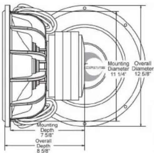
| Einbaudurchmesser | 285,8 mm (11 1/4 Zoll) |
| Gesamtdurchmesser | 320,7 mm (12 5/8 Zoll) |
| Einbautiefe | 193,7 mm (7 5/8 Zoll) |
| Gesamttiefe | 219,1 mm (8 5/8 Zoll) |
| Empfohlenes Gehäusevolumen (geschlossen) | 1,0 Kubikfuß (ca. 28,3 Liter) |
| Empfohlenes Gehäusevolumen (belüftet) | 1,5 bis 1,8 Kubikfuß (ca. 42,5 bis 51,0 Liter) |
| Frequenzgang (-3 dB geschlossen) | 52 Hz |
Häufig gestellte Fragen - OPTI1233D Lanzar
Benutzerfragen zu OPTI1233D Lanzar
0 Frage zu diesem Gerät. Beantworten Sie die, die Sie kennen, oder stellen Sie Ihre eigene.
Eine neue Frage zu diesem Gerät stellen
Laden Sie die Anleitung für Ihr Subwoofer kostenlos im PDF-Format! Finden Sie Ihr Handbuch OPTI1233D - Lanzar und nehmen Sie Ihr elektronisches Gerät wieder in die Hand. Auf dieser Seite sind alle Dokumente veröffentlicht, die für die Verwendung Ihres Geräts notwendig sind. OPTI1233D von der Marke Lanzar.
BEDIENUNGSANLEITUNG OPTI1233D Lanzar
Lanzar®
OPTIDRIVE
text_image
Mounting Diameter 11 1/4" Overall Diameter 12 5/8" Mounting Depth 7 5/8" Overall Depth 8 5/8"SPECIFICATIONS
Lanzar® Opti-Series Woofer for small enclosures
| Performance Parameters | OPTI1233D | Physical & Installation Parameters | ||
| Power (Watts RMS) | 3000W | 3000W | Voice | 3" BACCAR |
| Power (Watts Peak) | 6000W | 6000W | Magnet | 125oz x 3 |
| Individual Impedance | 1.3 ohm | 1.3 ohm | Cone | Black Laminated Pulp |
| Nom. Impedance | 1 ohm | 3 ohm | Surround | Foam |
| Re (ohms) | 0.65 | 2.6 | Spider | Polyester Cotton Composite |
| Fs (Hz) | 52 | 52 | Dustcap | Mica |
| Qms | 4.251 | 4.969 | Frame | Cast Aluminum |
| Qes | 0.908 | 0.966 | Terminals | Direct Connect 8 Gauge Wire |
| Qts | 0.748 | 0.809 | ||
| X-Max(mm) | 15.5 | 15.5 | ||
| Vas(cu. ft.) | 0.531 | 0.533 | ||
Lanzar continually strives to improve the performance and value of its-products: tail specifications are subject to change.
Suggested enclosure parameters
| speaker model | Sealed | Vented | |||
| Small | Large | Small | Large | ||
| OPTI 1233D | Enclosure volume, cu. ft.Sealed or vented | 1.0 | NA | 1.5 | 1.8 |
| Vent length, inches | 10 | 10 | |||
| Vent diameter, inches | 5 | 5 | |||
| Enclosure Frequency, Hz | 64 | ||||
| Fb Tuning Frequency of the Vented Enclosure | NA | 45.83 | 41.84 | ||
| F3 Systems 3dB Down Piont (Sealed) | 52 | ||||
Lanzar® Opti SERIES Woofer Specifications
Lanzar®
OPTIDRIVE
SPECIFICATIONS
text_image
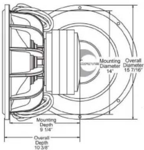
Mounting Diameter 14" Overall Diameter 15 7/16" Mounting Depth 9 1/4" Overall Depth 10 3/8"Lanzar® Opti-Series
Woofer for small enclosures
| Performance Parameters | OPTI1533D | Physical & Installation Parameters | ||
| Power (Watts RMS) | 3000W | 3000W | Voice | 3" BACCAR |
| Power (Watts Peak) | 6000W | 6000W | Magnet | 125oz x 3 |
| Individual Impedance | 1.3 ohm | 1.3 ohm | Cone | Black Laminated Pulp |
| Nom. Impedance | 1 ohm | 3 ohm | Surround | Foam |
| Re (ohms) | 0.65 | 2.6 | Spider | Polyester Cotton Composite |
| Fs (Hz) | 50 | 50 | Dustcap | Mica |
| Qms | 5.803 | 6.586 | Frame | Cast Aluminum |
| Qes | 1.44 | 1.44 | Terminals | Direct Connect 8 Gauge Wire |
| Qts | 1.154 | 1.182 | ||
| X-Max(mm) | 13 | 13 | ||
| Vas(cu. ft.) | 1.083 | 1.072 | ||
Lanzar continually strives to improve the performance and value of its-products (all specifications are subject to change.
Suggested enclosure parameters
| speaker model | Sealed | Vented | |||
| Small | Large | Small | Large | ||
| OPTI 1533D | Enclosure volume, cu. ft.Sealed or vented | 2.0 | 2.0 | 3.0 | |
| Vent length, inches | 8 | 8 | |||
| Vent diameter, inches | 5 | 5 | |||
| Enclosure Frequency, Hz | 62 | ||||
| Fb Tuning Frequency of the Vented Enclosure | 42.31 | 35.55 | |||
| F3 Systems 3dB Down Piont (Sealed) | 45 | ||||
Lanzar® Opti SERIES Woofer Specifications
choose this type of enclosure for: • Increased bass response
• Enhanced efficiency
- Tuneable enclosure
VENTED ENCLOSURES
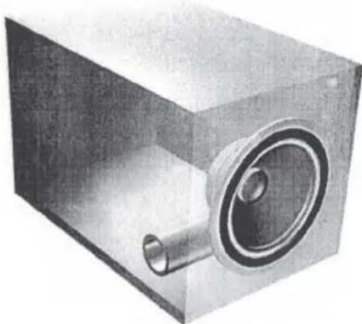
Vented enclosures, also known as "bass reflex" or "ported enclosures," utilize a tuned vent, called at "duct" or "port." This vent captures the energy of the woofer's backwave to increase bass response and efficiency. The tuning frequency of the enclosure can be altered by changing either the size or the length of the vent. This means that the user can modify the bass output without changing the enclosure. Because the port supplies a portion of the bass to the listener, the port and the speaker must both vent into the vehicle's interior Here are some general guidelines for utilizing vents on your enclosure:
- Vents can be of any shape. Use a material that is easy to work with when constructing the ducts. Cardboard mailing tubes or PVC pipe work well as port tubes. Remember to keep the port opening, inside and outside of the enclosure, free of obstructions for a distance equal to or greater than the port diameter.
- Typically, the larger the vent, the less duct noise created from the air being moved in and out. As the vent gets larger in diameter, the same tuning frequency can only be maintained by extending the length of the duct. The duct may extend beyond the outside of the enclosure or bend internally in order to achieve the desired length. Ultimately, the limitations of the size and length of the duct will be determined by the physical dimensions of the enclosure and installation area.
- When installing vents in the enclosure, try to keep the vent at least one vent diameter from any wall and at least two vent diameters from the woofer. There are pressure differences that exist surrounding the woofer and in proximity to the enclosure wall that can keep the vent from performing as designed.
- Because of lack of space in the enclosure, reducing the size of the vent or allowing the duct to protrude out of the enclosure are options that the occasional installation may require. Another method to get a duct to fit in an enclosure would be to use PVC pipe for the duct and a PVC elbow to create a bend in the duct. The length of the duct should be measured at its center to determine the length.
natural_image
3D rendering of a metallic mechanical component with a circular housing and cylindrical shaft (no text or symbols visible)FIG 2: Example of a vented enclosure
choose this type of enclosure for: • Control of both low end response and high end cutoff
• Increased efficiency and lower distortion
- Can eliminate need for crossovers or electronics in signal path
BandPASS ENCLOSURES
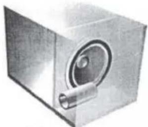
Bandpass enclosures can be constructed in many different configurations. Often referred to as 4 th, 5th, 6th, 7th, or 8th order enclosures, these enclosures are named based on the sum of their highpass and lowpass orders. The common characteristics between all bandpass enclosures is that one can control both the low end response and the high end cutoff. This capability allows the user tremendous flexibility when tailoring a sound system to a particular vehicle.
Another benefit of the bandpass enclosure can be increased efficiency. Typical passband efficiency gains are in the 3db range, but gains over twice that amount can be achieved in some configurations. Lower distortion is also attainable because bandpass systems can integrate their own acoustic low pass filter, making it possible to eliminate low end passive inductors or electronic crossovers from the signal path.
Yet another benefit in bandpass enclosures is ease of installation. With a bandpass enclosure, all of the sound is delivered through a vent (s). This can be a big help in dealing with space limitations by only requiring enough area to vent the enclosure into the vehicle, not the entire woofer opening.
Critics of bandpass enclosures feel that because all of the sound is delivered through a vent, sound quality may suffer (when compared to other direct firing enclosures). A consideration when contemplating using a bandpass enclosure is the complexity of the enclosure. The box is more difficult to build and accessibility to the woofer for servicing is limited.
In a 4th order bandpass enclosure (12db slope for highpass and lowpass), the woofer low frequency tuning is determined by the volume of the rear sealed enclosure. The vent determines the frequency for the acoustic low pass filter, while the volume of the front compartment determines the response curve in the passband. The greater the volume of the front compartment the greater is the rise in the mid passband. Conversely, the smaller the front compartment the greater is the dip. By adding a series inductor to a 4th order bandpass enclosure it becomes a 5th order enclosure with a 18db lowpass rolloff.
A 6th order bandpass (or "dual vented") bandpass enclosure will have a rear chamber vent. This enclosure works similarly to a 4th order enclosure, with the efficiency and low frequency control of a vented system added. Similarly to other vented enclosures, the enclosure provides little control for the woofer below the tuned frequency of the vent. With both 6th order bandpass or vented enclosures a sub sonic or low frequency filter can aid in reducing inaudible and often excessive cone excursions, thereby minimizing premature driver failure.
All rules applying to building sealed or vented enclosures apply to constructing bandpass enclosures. The enclosures must be sealed, vents must be unobstructed and kept away from enclosure walls.
natural_image
3D rendering of a metallic cube with a circular component and cylindrical shaft (no text or symbols)FIG 3: Example of a sealed bandpass enclosure
natural_image
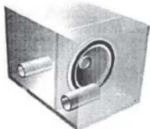
3D rendering of a metallic mechanical component with cylindrical and circular features (no text or symbols)FIG 4: Example of a vented bandpass enclosure
Lanzar Woofer Manual