VCT2510 - Empfänger Lanzar - Kostenlose Bedienungsanleitung
Finden Sie kostenlos die Bedienungsanleitung des Geräts VCT2510 Lanzar als PDF.


Benutzerfragen zu VCT2510 Lanzar
0 Frage zu diesem Gerät. Beantworten Sie die, die Sie kennen, oder stellen Sie Ihre eigene.
Eine neue Frage zu diesem Gerät stellen
Laden Sie die Anleitung für Ihr Empfänger kostenlos im PDF-Format! Finden Sie Ihr Handbuch VCT2510 - Lanzar und nehmen Sie Ihr elektronisches Gerät wieder in die Hand. Auf dieser Seite sind alle Dokumente veröffentlicht, die für die Verwendung Ihres Geräts notwendig sind. VCT2510 von der Marke Lanzar.
BEDIENUNGSANLEITUNG VCT2510 Lanzar

text_image
Lanzar® VECTORLanzar Audio Inc. 1600 63rd Street, Brooklyn, NY 11204 (718) 236-8000 www.lanzar.com

text_image
Lanzar® VECTORVCT-2110 VCT-2210 VCT-2310 VCT-2410 VCT-2510

natural_image
Exterior view of a black and white electronic device with a star-shaped logo on the front panel (no readable text or symbols)AMERICAN CRAFTED PERFORMANCE
Owner's Manual
www.ianzar.com
congratulations...
Congratulations on your purchase of a Lanzar VECTOR series amplifier. You have purchased a quality product designed and engineered to give you many years of uncompromised musical service. VECTOR series amplifiers are designed with the latest technology available, which provides headroom for even the most demanding peaks and dynamic ranges found on modern CDs and recordings.

text_image
LanzarLinzor VECTOR OWNER'S MANUAL
table of contents
features and specifications
VCT-2110/VCT-2210
VCT-2310/VCT-2410/VCT-2510
electrical connections
VCT-2110/VCT-2210
VCT-2310/VCT-2410/VCT-2510
stereo/mono input connections
VCT-2110/VCT-2210
VCT-2310/VCT-2410/VCT-2510
system wiring speaker connections
VCT-2110/VCT-2210
VCT-2310/VCT-2410/VCT-2510
11
mounting and installation
12
protection circuitry and troubleshooting
13
precautions
14
LAVOUR VECTOR OWNER'S MANUAL - 1
features and specifications
2 ch amp VCT-2110 · VCT-2210
crossover made selector
When used with account, full range system, set this switch for TUL1.
If you wish to use the virtual crossover to power a other or specific
frequency range, use the LFF or HPF FOR the COMPASS' OR
HIGHPASS' settings
input level controls
Enables the matching of input levels to the output levels from head unit
crossbar frequency centre
When crosslinked mode parameter is to HIGH/ASS modes. And crosslinked
The lower frequency check for audio programs such to the sponsors.
What crossover mode selector is to LOWPASS mode, this control set
The super-frequency kind for and the program sent to the speakers.
The crosslink is continuously variable adjustment from 40 to 250 Hz
This detector switches to the base level as increase of 1865
(06721192210)
low level input This crop features R24 type seeds for high impedance input.
Use these with car stereo output which uses RCA type connector cables.
high level input. If your car stereo sticks are not RCA low output, are the high-flow line
The adjector is current the answer output level of capacitor and the
AQA was a key of step
VIX line outputs - This new features RCA lacks for AUX line outputs.
Due these for unlimited system expansion in the next VECTOR.
power LED. This indicator is eliminated in GREEN when power is applied.
protection LED This industry is eliminated in RED when the full production capacity
is activated
prevent here. The base projects the activities and plans for a biological system from animal
of our credit
power chemicals. How these connect to deliver power, grassy, and tropical (water) crystals
In the annual Sex
poker connectors
2017年,安徽国盛3.1572
| output power @ 14.4x DC, 1MHz | VCT-2110 | VCT-2210 |
| RMS Power @ 4 Ohms | 50 Watts x 2 | 100 Watts x 2 |
| TND @ 4 Ohms | 75 Watts x 2 | 150 Watts x 2 |
| RMS Power @ 2 Ohms | 75 Watts x 2 | 150 Watts x 2 |
| TND @ 2 Ohms | 100 Watts x 2 | 200 Watts x 2 |
| Maximare Power Output | 500 Watts x 2 | 1000 Watts x 2 |
| Bridged Power at 4 Output | 1000 Watts x 1 | 2000 Watts x 1 |
Итогосяческая — 15 кг, 20 кг
(1) 2017年1月1日
Input imporance
Low Level Insurfs
low fixed prices
Impact security
low /noo/ /neuts
2017年1月1日
S/N ration
net separation
crossover filters
Лим Раха
New Door High Pass
high rate
hats brevet
eveler impedance
clovas made
stereo mode brided mode
Invited more
ram canell draw
supply voltage
esluire DR x N x li
02
(arches
194305
1540.27460
5.16 30 M
[Non-Text]
10K Close
m = 311
[Non-Text]
201km EV Adjustable
2019-17 Adjusted
The Ground Truth image displays a single, solid horizontal line, which is a stylistic or background element (like a rule line on paper). According to Rule 2, such lines must be ignored by the OCR result. The provided OCR content is "____", which consists of underscores. Underscores are not equivalent to a solid line and are not permitted under the “Stylistic/Background Lines (Ignore)” rule. Outputting underscores for a stylistic line is incorrect because it misinterprets the line as a placeholder fill-in-the-blank area. Since the OCR output incorrectly rendered a stylistic line as underscores (which should be ignored), this violates the rule. Therefore, the OCR result is inconsistent with the Ground Truth.
The Ground Truth image displays a single, solid horizontal line. According to Rule 2 (UNDERSCORE & LINE RULES), if the GT contains lines used for stylistic emphasis or as background elements (like ruled paper), the OCR result must ignore them. The OCR content provided is "____", which consists of four underscores. This is incorrect because underscores are not equivalent to a solid line and are not permitted under the “Stylistic/Background Lines (Ignore)” rule. The OCR has hallucinated underscores where none should exist in the GT, violating the rule to ignore stylistic lines. Therefore, the OCR result is inconsistent with the Ground Truth.
-
m = 311
m = 311
-
The Ground Truth image displays a single, solid horizontal line. According to Rule 2 (UNDERSCORE & LINE RULES), this is a stylistic or background line, not a placeholder underscore. Therefore, the OCR result must ignore it and output nothing or only meaningful text. The provided OCR content is "____", which consists of four underscores. This is an incorrect interpretation of the line as a placeholder, violating the rule that stylistic lines must be ignored. The OCR has hallucinated underscores where none should exist based on the GT's visual context. Hence, the OCR result is inconsistent with the Ground Truth.
广力云智慧零售收银系统
m = 311
(1)
1
59
14.4V DC No. Ground (10.5-16K)
- 2017
20×M5×278
963×1.75×0
0.16×1.75×3
- 2017年1月1日
(二)
(1)
-
m = 311
[Non-Text]
table ____
[Unreadable]
—
(No text)
[Non-Text]
m = 311
(No text)
(1) 本说明仅供参考。
(No text)
[Non-Text]
m = 311
(五)
2014
404
(12.5-1610)
(14.6.20)
201x44.5x305
0.51×1.75×12
0.02 × 1,75 × 12


r VECTOR OWNER'S MANUAL
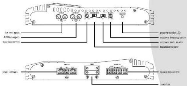
features and controls
2 ch amp VCT-2110 · VCT-2210
text_image
low level inputs AUX line outputs input level control power terminal power detection LED crossover frequency control crossover mode selector Base Base selector power terminals speaker connections power fuse


features and specifications
2 ch amp VCT-2310 · VCT-2410 · VCT-2510
| crossover mode selector | When used with normal, full range system, and this switch to TOLLC. If you switch to use the internal crossover to power a driver or specific frequency range, use the LPT for NPT (L10/PAGE) ON | output power # 14.4V, K10c | VCT-2310 | VCT-2410 | VCT-2510 |
| level input controls | Analog/Amplifier/Amplifier | RMS Power # 0.0 Vcs | 180Vrms x 2 | 200Vrms x 2 | 300Vrms x 2 |
| THD # 0.0 Vcs | 200Vrms x 2 | 300Vrms x 2 | 400Vrms x 2 | ||
| Finishing the encoding of input leads to the output leads (have best used in the network). | RMS Power # 2.0 Vcs | 200Vrms x 2 | 200Vrms x 2 | 400Vrms x 2 | |
| THD # 2.0 Vcs | 200Vrms x 2 | 300Vrms x 2 | 500Vrms x 2 | ||
| receiver frequency control | When crossover mode selection is in L10/PAGE/STS, this control sets the lower frequency design for a power program set to the speakers. | Maximum Power Output | 200Vrms x 2 | 200Vrms x 2 | 300Vrms x 2 |
| Bridged Power at 4 Output | 400Vrms x 1 | 400Vrms x 1 | 500Vrms x 1 | ||
| frequency response | 15 Hz-30 kHz | ||||
| bass boost level control | When crossover mode selection is in L10/PAGE/STS, this control sets the lower frequency design for a power program set to the speakers. | Input impedance | |||
| Low level Inputs | 100 GHz | ||||
| Input sensitivity | |||||
| peak control | The nominal peak controller uses the base level up to an increase of capacitance up to the back. (VCT-27160/HD/HD) | ||||
| peak control | The nominal peak controller uses to a 1.0V max, then low control permits continuously variable adjustment from 10 to 100Hz (VCT-27160/HD/HD) | ||||
| low level input | The ramp speed of RGA gate peaks for high impedance input. | Channel perpendicular crossover filters | |||
| Low Pass | 40 Hz-250 Hz | ||||
| High Pass | 40 Hz-250 Hz | ||||
| high level input | Uses these with all control outputs which uses RGA type connector cables for your current outputs are on RGA type output, using the high level input signal output to the speaker output branch of one channel and the RGA input peaks of amp. | Base Asset | 0 ~1/6Hz | ||
| Peak Filter | 10-100 Hz | ||||
| link line outputs | The ramp functions RGA peaks for ADR low outputs. Use the ramp function system for an SEDF/STOR. | Peak filter | |||
| matching speaker experience | |||||
| power LED | The indicator is illuminated in SEED when power is applied. | stroke mode | 2.4 GHz | ||
| protection LED | The indicator is illuminated in REE when the battery protection activity is controlled mode. | brapped mode | 4.8 GHz | ||
| power fuses | The load protected by the amplifier and power a electrical system have what was connected. | maximum correct drive | 50A | 80A | 60A |
| power formulates | Use these components to deliver power, ground, and mode of connection to the power. | power supply voltage | 14.4V DC | Ning. Ground (10.5-16V) | |
| speaker connectors | These formulates are to facilitate high conductivity and maximum signal loss | emotion | 270x 44.5x 43.9 | 270x 44.5x 43.9 | 270x 44.5x 53.2 |
| Inches | 10.8x 1.75x 1.9 | 10.8x 1.75x 1.7 | 10.8x 1.75x 2.9 | ||

the VECTOR OWNER'S MANUAL
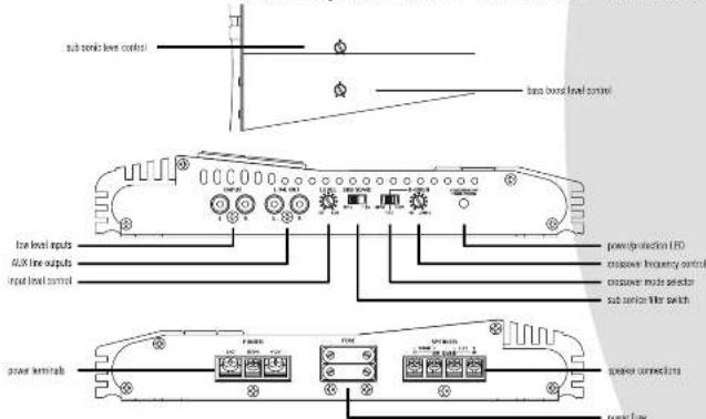
features and controls
2 ch amp VCT-2310 · VCT-2410 · VCT-2510
text_image
sub-sonic level control base based level control low level inputs AUX line outputs input level control power protection LED crossover frequency control crossover mode selector sub-sonic filter switch power terminals power connections power fuses
VECTOR OWNER'S MANUAL - 5
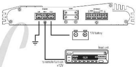
electrical connections
2 ch amp · VCT-2110 · VCT-2210
VCT-2310·VCT-2410
VCT-2510
text_image
12V battery to remote turn-on +12V head unitLinzur VECTOR OWNER'S MANUAL
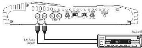
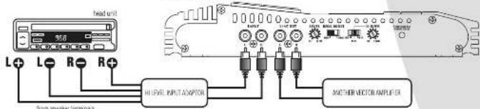
stereo input connections
2 ch amp · VCT-2110 · VCT-2210
using low level inputs
text_image
LRF Audio Outputs head unit 950using high level inputs
text_image
head unit L+ L- R- R+ HLEVEL INPUT/AMPTOR ANOTHER MOTOR AMPLIFIER Two analogs connectedL. VICTOR OWREK'S MANUAL - 7
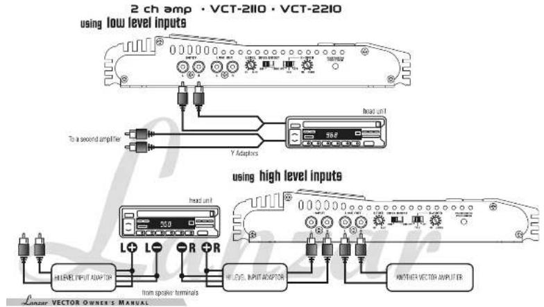
mono input connections
text_image
2 ch amp • VCT-2110 • VCT-2210 using low level inputs To a second amplifier head unit Y Adapters 968 used in using high level inputs head unit L+ L- R + R HI LEVEL INPUT ADAPTER from speaker terminals HI LEVEL INPUT ADAPTER ANOTHER VECTOR AMPLIUTER Linear VECTOR OWNER'S MANUALstereo input connections
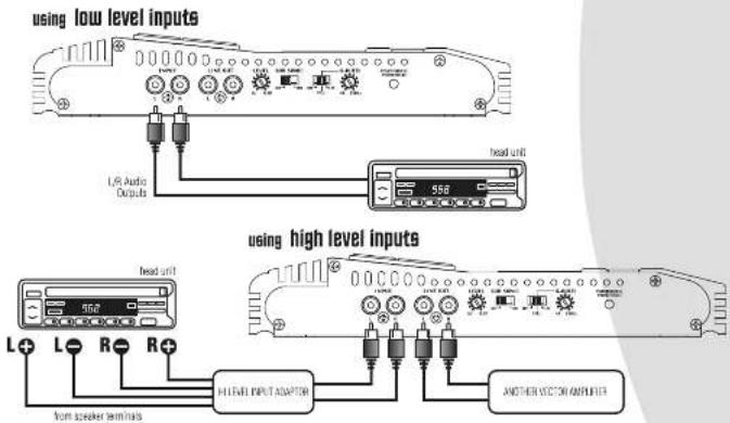
2 ch amp · VCT-2310 · VCT-2410 · VCT-2510
text_image
using low level inputs L/R Audio Outputs head unit 556 using high level inputs head unit L+ L- R- R+ from speaker terminals HLEVEL INPUT ADAPTER ANOTHER VIEW AMPLIFIERLancore VECTOR OWNER'S MANUAL - 9
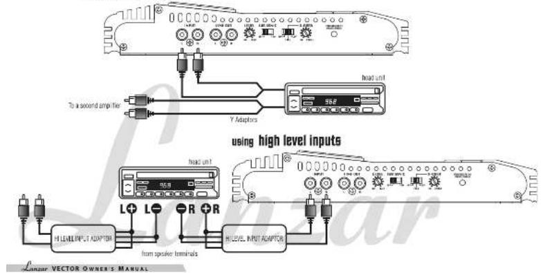
mono input connections
2 ch amp · VCT-2310 · VCT-2410 · VCT-2510 using low level inputs
text_image
using high level inputs from speaker terminals H LEVEL INPUT ADAPTER L+ L- R+ R head unit To a second amplifier Y Adapters head unit H LEVEL INPUT ADAPTER Linear VECTOR OWNER'S MANUALspeaker connections
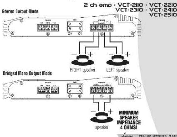
text_image
Stereo Output Mode 2 ch amp • VCT-2110 • VCT-2210 VCT-2310 • VCT-2410 VCT-2510 RIGHT speaker LEFT speaker Bridged Mono Output Mode MINIMUM SPEAKER IMPEDANCE 4 OHMS! speaker VECTOR OWNER'S MANmounting and installation
troubleshooting
mounting
Your new Targar Vector Series amplifier comes complete with all required mounting hardware. When determining a suitable location in your vehicle for the amp, please remember that it is a high-power electronic device capable of generating high heat.
For this reason, always choose a location in your vehicle which has low vibration, adequate ventilation, a minimum of dust, and no moisture. Be sure to mount the amp in such a manner as to allow reasonable airflow over the cooling fins.
Mark the location for the mounting screw holes by positioning the amp where you wish to install it and use a scribe (or one of the mounting screws) inserted in each of the mounting holes to mark the mounting surface. If the mounting surface is carpeted, measure the hole centers and mark with a felt tip pen.
Before attempting to drill the mounting holes, take note of any wires, lines or other devices in your vehicle which may be located behind the mounting surface! Then drill pilot holes in the mounting surface for the mounting screws and insert them. Tighten the screws securely
WING TING
When making electrical connections to your amplifier, please observe the following:
Use at least 8 gauge wire for power and ground connections.
Wire the amplifier directly to the car battery
For the ground connection, use the shortest possible wire to a good chassis ground point.
Wire the Remote connection to the auto start load of your head unit, equalizer or power antenna.
About power fuses:
Lanzar Vector Series ampifiers feature built-in fuse systems. These fuses protect both the amplifier and the electrical system in your vehicle from fault conditions. If you ever need to replace the fuse in your Lanzar Vector Series amp, use a fuse of exactly the same type and rating. A different type or rating of fuse may result in damage or tire.
protection circuitry
The built-in protection circuitry in the Lanzar Vector Series amplifiers will disabve the amplifier if it senses an input overload, a speaker short circuit, or extreme temperature conditions.
When the protection circuit is activated by any of these conditions, the Protection LED will be illuminated.
If this occurs, carefully inspect the system to determine the source of the problem.
- If the shutdown was a result of a thermal overload condition, allow the amplifier to cool down before attempting to restart it.
- If the shutdown was a result of an input overload, or speaker short circuit, be sure to correct the condition before restarting.
The amplifier can be restarted by turning the remote power OFF and then ON again.
No output
Confirms that all terminal ship connections are secure and light
Check both in-line and built-in tuses. Both the +12V and the Remote terminals must have +12V referenced to chassis ground
Confirm that the audio signal source (car radio, equalizer, etc.) is connected and is supplying output signal. To check if the amp is supplying signal, unplug the cables from the signal source (but leave them plugged into the amp). Briefly tap the center pin of each of the disconnected PCA plugs with your finger: This should produce a noise (feedback) in your speakers.
Only one channel works.
Confirm that all terminal strip connections are secure and tight.
Check the Balance control on the head unit (or other source) to verify that it is set to its midpoint.
If you are using the Low Level RCA input, reverse the input plugs at the amplifier (i.e., switch the I), with the Pi. If the channels which is silent switches to the other side, the problem is either in the head unit/other source or the connecting cables
Weak output.
Readjust the Input Level Control(s) to better suit the input signal.
Noise in the audio.
If the noise is a "whine" whose pitch follows the engine speed, confirm that the amplifier and any other signal sources (head unit, etc.) are properly grounded.
If the noise is a "clicking" or "popping" noise whose rate follows the engine speed, this usually means that the vehicle is equipped with resistor spark plugs and wires, or that the ignition is in need of service.
Check the mounting of the speaker and input wires to make sure they are not adjacent to wires which introconnect lights and other accessories.
If the above steps fail to improve or clear noise interference, the system should be checked by a professional mobile audio installer
LUNTER VECTOR OWNER'S MANUAL
VECTOR OWREK'S MANUAL - 13
precautions
Do not operate the amplifier when it is unmounted. Attach all audio system components securely within the automobile to prevent damage, especially in an accident.
Do not mount this amplifier so that the wire connections are unprotected, or in a pinched condition, or likely to be damaged by nearby objects.
Before making or breaking power connections in your system, disconnect the vehicle battery. Confirm that your head unit or other equipment is turned off while connecting the input jacks and speaker terminals
If you need to replace the power fuse, do so only with a fuse identical to that supplied with the amplifier. Using a fuse of a different type or rating may result in damage that isn't covered in the manufacturer's warranty.
notes
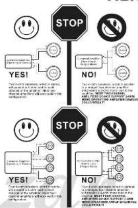
flowchart
graph TD
    A["STOP"] --> B{YES!}
    A --> C{NO!}
    B --> D["Emotional Emotion: Yes/No"]
    C --> E["Emotional Emotion: No/Yes"]
    D --> F["Stable Emotion: Yes/No"]
    E --> G["Stable Emotion: No/Yes"]
    F --> H["Stop"]
    G --> I["Stop"]
    H --> J["Stop"]
    I --> K["Stop"]
Lanzur VECTOR OWNER'S MANUAL