VIBE 421 - Autoradio Lanzar - Kostenlose Bedienungsanleitung
Finden Sie kostenlos die Bedienungsanleitung des Geräts VIBE 421 Lanzar als PDF.


Benutzerfragen zu VIBE 421 Lanzar
0 Frage zu diesem Gerät. Beantworten Sie die, die Sie kennen, oder stellen Sie Ihre eigene.
Eine neue Frage zu diesem Gerät stellen
Laden Sie die Anleitung für Ihr Autoradio kostenlos im PDF-Format! Finden Sie Ihr Handbuch VIBE 421 - Lanzar und nehmen Sie Ihr elektronisches Gerät wieder in die Hand. Auf dieser Seite sind alle Dokumente veröffentlicht, die für die Verwendung Ihres Geräts notwendig sind. VIBE 421 von der Marke Lanzar.
BEDIENUNGSANLEITUNG VIBE 421 Lanzar
Lanzar
AMERICAN CRAFTED
natural_image
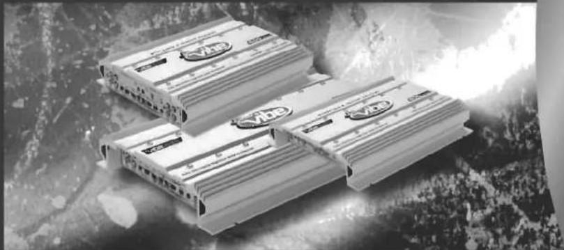
Black-and-white photo of stacked Vibo devices with 'vib' branding, set against a dark textured background (no readable text or symbols)Owner's Manual
natural_image
Exterior view of a white electronic device with control knobs and indicator lights (no visible text or symbols)PERFORMANCE
vibe211
vibe221
vibe231
vibe241
vibe251
vibe26
vibe411
vibe421
vibe431
vih 501

Congratulations on your purchase of a Lanzar Vibe amplifier. You have purchased a quality product designed and engineered to give you many years of uncompromised musical service. Vibe amplifiers are designed with the latest technology available, incorporating a DC to DC Switching Power Supply, which provides headroom for even the most demanding peaks and dynamic ranges found on modern CD's and recordings.
TABLE OF CONTENTS
i Table of Contents
Features and Controls
1 vibe 211/221/231/241/251/261
2 vibe 411/421/431
vibe 531
4 Specifications
6 Installation
System Wiring
7 2 channel stereo
8 2 channel bridged mode
9 2 channel tri-mode
10 2 channel triamp system
11 4 channel stereo
12 4 channel bridged mode
13 4 channel tri-mode
14 5 channel stereo
15 5 channel bridged mode
16 5 channel tri-mode
17 Troubleshooting
FEATURES
• MOSFET switches maintain rated power over a wide range of battery voltages
• Stiffly regulated PWM-type power supplies
• 2 Ohm Stable Stereo operation
• Variable input level controls for each pair of channels
Variable high and low pass crossover controls
• Thermal and speaker short protection circuitry
• Power and Protection LED indicators
- Bass Boost Circuitry
- Stereo, Bridge Mode and Tri-Mode System Application Compatible
• Gold plated power, RCA and speaker connectors
• High-efficiency, heavy aluminum heatsink
• Bass Boost Remote control
1 - Lanzar VIBE OWNER'S MANUAL
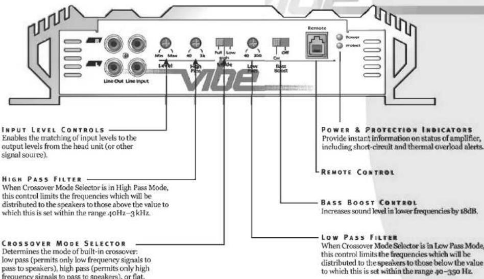
FEATURES AND CONTROLS VIBE 211/221/231/241/251/261
text_image
Line Out Line Input Input Level Controls Enables the matching of input levels to the output levels from the head unit (or other signal source). HIGH PASS FILTER When Crossover Mode Selector is in High Pass Mode, this control limits the frequencies which will be distributed to the speakers to those above the value to which this is set within the range 40Hz–3kHz. CROSSOVER MODE SELECTOR Determines the mode of built-in crossover: low pass (permits only low frequency signals to pass to speakers), high pass (permits only high frequency signals to pass to speakers), or flat. Power & PROTECTION INDICATORS Provide instant information on status of amplifier, including short-circuit and thermal overload alerts. REMOTE CONTROL BASS BOOST CONTROL Increases sound level in lower frequencies by 18dB. LOW PASS FILTER When Crossover Mode Selector is in Low Pass Mode, this control limits the frequencies which will be distributed to the speakers to those below the value to which this is set within the range 40–350 Hz.Lanzar VIBE OWNER'S MANUAL - 1
FEATURES AND CONTROLS
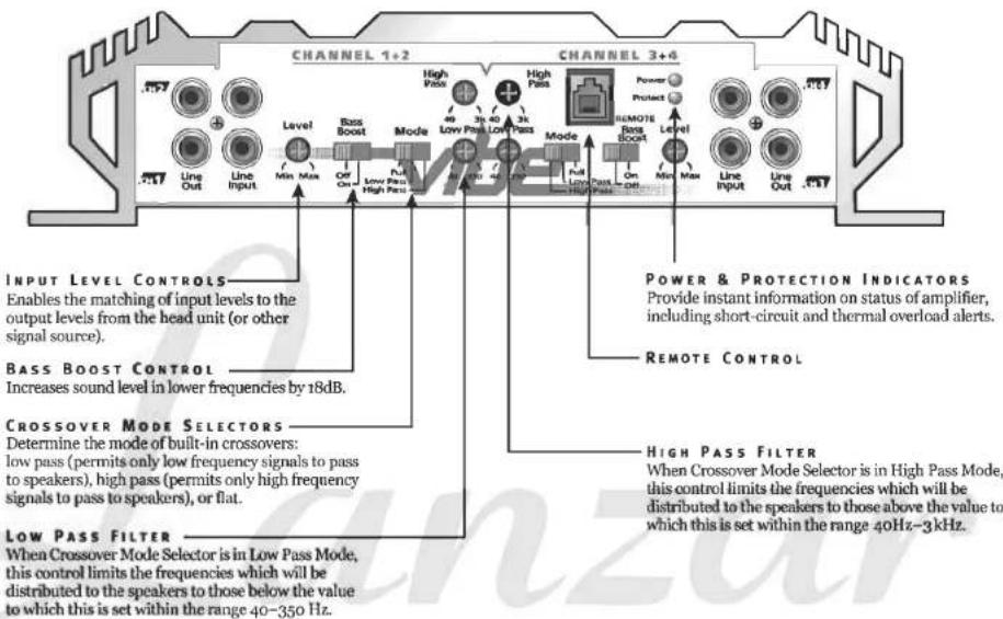
VIBE 411/421/431
text_image
CHANNEL 1+2 CHANNEL 3+6 INPUT LEVEL CONTROLS Enables the matching of input levels to the output levels from the head unit (or other signal source). BASS BOOST CONTROL Increases sound level in lower frequencies by 18dB. CROSSOVER MODE SELECTORS Determine the mode of built-in crossovers: low pass (permits only low frequency signals to pass to speakers), high pass (permits only high frequency signals to pass to speakers), or flat. LOW PASS FILTER When Crossover Mode Selector is in Low Pass Mode, this control limits the frequencies which will be distributed to the speakers to those below the value to which this is set within the range 40Hz-3kHz. POWER & PROTECTION INDICATORS Provide instant information on status of amplifier, including short-circuit and thermal overload alerts. REMOTE CONTROL High Pass FILTER When Crossover Mode Selector is in High Pass Mode, this control limits the frequencies which will be distributed to the speakers to those above the value to which this is set within the range 40Hz-3kHz.2 - Lanzar VIDE OWNER'S MANUAL
FEATURES AND CONTROLS
VIBE 531
text_image
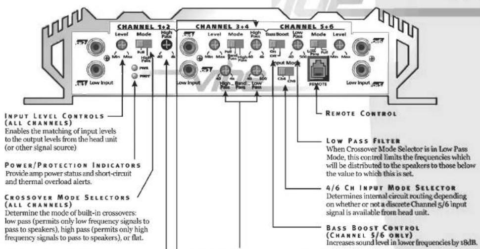
CHANNEL 1+2 CHANNEL 3+4 CHANNEL 5+6 INPUT LEVEL CONTROLS (ALL CHANNELS) Enables the matching of input levels to the output levels from the head unit (or other signal source) POWER/PROTECTION INDICATORS Provide amp power status and short-circuit and thermal overload alerts. CROSSOVER MODE SELECTORS (ALL CHANNELS) Determine the mode of built-in crossovers: low pass (permits only low frequency signals to pass to speakers), high pass (permits only high frequency signals to pass to speakers), or flat. CHANNEL 5+2 Level Mode High Pass Low Input Mode High Pass Low Input Mode High Pass Low Input Mode High Pass Low Input Mode High Pass Low Input Mode High Pass Low Input Mode High Pass Low Input Mode High Pass Low Input Mode High Pass Low Input Mode High Pass Low Input Mode High Pass Low Input Mode High Pass Low Input Mode High Pass Low Input Mode High Pass Low Input Mode High Pass Low Input Mode High Pass Low Input Mode High Pass Low Input Mode High Pass Low Input Mode High Pass Low Input Mode High Pass Low Input Mode High Pass Low input mode Level Mode High Pass Low Input Mode High Pass Low Input Mode High Pass Low Input Mode High Pass Low Input Mode High Pass Low Input Mode High Pass Low Input Mode High Pass Low Input Mode High Pass Low Input Mode High Pass Low Input Mode High Pass Low Input Mode High Pass Low Input Mode High Pass Low Input Mode High Pass Low Input Mode High Pass Low Input Mode High Pass Low Input Mode High Pass Low Input Mode High Pass Low Input Mode High Pass Low Input Mode High Pass Low Input Mode High Path Low Input Power PHOT Input Mode ChA ChB REMOTE CONTROL LOW PASS FILTER When Crossover Mode Selector is in Low Pass Mode, this control limits the frequencies which will be distributed to the speakers to those below the value to which this is set. 4/6 CH INPUT MODE SELECTOR Determines internal circuit routing depending on whether or not a discrete Channel 5/6 input signal is available from head unit. BASS BOOST CONTROL (CHANNEL 5/6 ONLY) Increases sound level in lower frequencies by 18dB.HIGH PASS FILTERS
When Crossover Mode Selector is in High Pass Mode, these controls limit the frequencies which will be distributed to the speakers to those above the values to which these are set.
BAND PASS CROSSOVER CONTROLS
(CHANNEL 3/4 ONLY)
When Ch 3/4 Crossover Mode Switch is in Band Pass position, these two controls are used to establish the upper and lower frequency range limits for the signals which will be distributed to the Ch 3/4 speakers.
Lanzar VIBE OWNER'S MANUAL - 3
SPECIFICATIONS
| MODEL | vibe211 2 channel amplifier | vibe221 2 channel amplifier | vibe231 2 channel amplifier | vibe241 2 channel amplifier |
| RMS at 4 Ohms | 2 x 90W | 2 x 150W | 2 x 200W | 2 x 250W |
| MAX at 4 Ohms | 2 x 180W | 2 x 300W | 2 x 400W | 2 x 500W |
| At 4 Ohms Bridged | 1 x 360W | 1 x 600W | 1 x 800W | 1 x 1000W |
| RMS at 2 Ohms | 2 x 150W | 2 x 250W | 2 x 350W | 2 x 420W |
| Min. Speaker Impedance | 2 Ohm | 2 Ohm | 2 Ohm | 2 Ohm |
| T.H.D | 0.04% | 0.04% | 0.04% | 0.04% |
| Frequency Response | 15Hz-35kHz, -1dB | 15Hz-35kHz, -1dB | 15Hz-35kHz, -1dB | 15Hz-35kHz, -1dB |
| Input Sensitivity | 100mV-4000mV | 100mV-4000mV | 100mV-4000mV | 100mV-4000mV |
| Input Impedance | 22 kOhm | 22 kOhm | 22 kOhm | 22 kOhm |
| S/N Ratio | >90dB | >90dB | >90dB | >90dB |
| Channel Separation | >65dB | >65dB | >65dB | >65dB |
| Crossover Filters | ||||
| Low Pass | 40Hz-350kHz | 40Hz-350kHz | 40Hz-350kHz | 40Hz-350kHz |
| High Pass | 40Hz-3 kHz | 40Hz-3 kHz | 40Hz-3 kHz | 40Hz-3 kHz |
| Bandpass | n/a | n/a | n/a | n/a |
| Bass Boost | +18dB | +18dB | +18dB | +18dB |
| Dimensions (Inches) | 10.25 x 2 x 8 (WxHxL) | 10.25 x 2 x 10 (WxHxL) | 10.25 x 2 x 12 (WxHxL) | 10.25 x 2 x 15 (WxHxL) |
| Fuse(s) | 15A | 20A | 25A | 15A x 2 |
4 - Lanzar VIBE OWNER'S MANUAL
| vibe251^2 channel amplifier | vibe261^2 channel amplifier | vibe411^4 channel amplifier | vibe421^4 channel amplifier | vibe431^4 channel amplifier | vibe531^5 channel amplifier |
| 2 x 400W | 2 x 600W | 4 x 75W | 4 x 125W | 4 x 150W | 4 x 100W + 1 x 200W |
| 2 x 800W | 2 x 1200W | 4 x 150W | 4 x 250W | 4 x 300W | 4 x 200W + 1 x 400W |
| 1 x 1600W | 1 x 2400W | 2 x 300W | 2 x 500W | 2 x 600W | 2 x 400W + 1 x 600W |
| 2 x 650W | 2 x 1000W | 4 x 125W | 4 x 200W | 4 x 250W | 4 x 175W + 1 x 375W |
| 2 Ohm | 2 Ohm | 2 Ohm | 2 Ohm | 2 Ohm | 2 Ohm |
| 0.04% | 0.04% | 0.04% | 0.04% | 0.04% | 0.04% |
| 15Hz-35kHz, -1dB | 15Hz-35kHz, -1dB | 15Hz-35kHz, -1dB | 15Hz-35kHz, -1dB | 15Hz-35kHz, -1dB | 15Hz-35kHz, -1dB |
| 100mV-4000mV | 100mV-4000mV | 100mV-4000mV | 100mV-4000mV | 100mV-4000mV | 100mV-4000mV |
| 22 kOhm | 22 kOhm | 22 kOhm | 22 kOhm | 22 kOhm | 22 kOhm |
| >90dB | >90dB | >90dB | >90dB | >90dB | >90dB |
| >65dB | >65dB | >65dB | >65dB | >65dB | >65dB |
| 40Hz-350kHz80Hz-2.50kHzn/a | 40Hz-350kHz40Hz-3 kHzn/a | 40Hz-350kHz40Hz-3 kHzn/a | 40Hz-350kHz40Hz-3 kHzn/a | 40Hz-350kHz40Hz-3 kHzn/a | 40Hz-500Hz40Hz-4kHzvariable, 40Hz-4kHz(HPF),40Hz-500Hz(LPF) |
| +18dB | +18dB | +18dB | +18dB | +18dB | +12dB |
| 10.25 x 2 x 19 (WxHxL) | 10.25 x 2 x 21 (WxHxL) | 10.25 x 2 x 12 (WxHxL) | 10.25 x 2 x 14 (WxHxL) | 10.25 x 2 x 17 (WxHxL) | 10.25 x 2 x 24 (WxHxL) |
| 25A x 2 | 40A x 2 | 15A x 2 | 20A x 2 | 25A x 2 | 30A x 2 |
Lanzar VIBE OWNER'S MANUAL - 5
INSTALLATION
- Find a suitable location in the vehicle to mount the amplifier.
- Make sure there is sufficient air flow around the intended mounting location.
- Bolt the amplifier to the mounting surface.
- Connect the power ground terminal to the nearest point on the chassis of the car. Keep this ground wire less than one meter (39") in length. Use 8 gauge wire.
- Connect the remote terminal to the remote output of the head unit using 14 gauge wire.
- Connect an empty fuse holder within 300 mm (12") of the battery and run 8 gauge or larger high quality cable from this fuse to the amplifier location.
- Make sure there is no fuse in this fuse holder. Then make the connection to the "BATT" connection on the amplifier.
- If multiple amplifiers are being used, use cables (each with its own fuse at the battery) or a #0 or #2 cable from the fuse holder at the battery to a distribution block at or near the amplifier's location.
- Connect all line inputs and outputs using high-quality RCA-RCA cables.
- Insert fuse(s) at the battery fuse holder(s).
- Recheck all connections before powering up.
- Set all level controls to their least sensitive positions and set all crossover controls, switches, etc. to the desired frequency or position.
- Once the system is powered up, set the volume control on the head unit to about the 2 o'clock position, and then set all the amplifiers' level controls for maximum output level.
- Further fine tuning of the various controls may be necessary to obtain the desired results.
PRECAUTIONS
- Before you drill or cut any holes, investigate your car's layout very carefully. Take care when you work near the gas tank, fuel lines, hydraulic lines and electrical wiring.
- Do not operate the amplifier when it is unmounted. Attach all audio system components securely within the automobile to prevent damage, especially in an accident.
- Do not mount this amplifier so that the wire connections are unprotected or in a pinched condition, or likely to be damaged by nearby objects. Be sure to select a location inside your vehicle which has adequate ventilation.
- Before making or breaking power connections in your system, disconnect the vehicle battery. Confirm that your head unit or other equipment is turned off while connecting the input jacks and speaker terminals.
- If you need to replace the power fuse, only replace it with a fuse identical to that supplied with the system. Using a fuse of a different type or rating may result in damage to your system which isn't covered by the manufacturer's warranty.
vibe211/221/231/241/251/261
SYSTEM WIRING
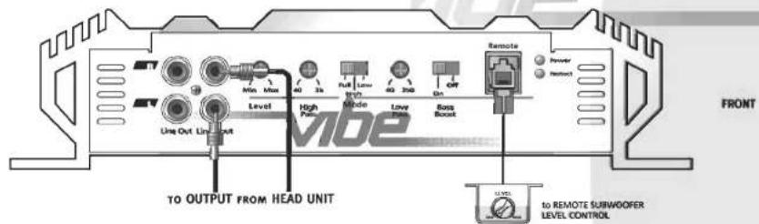
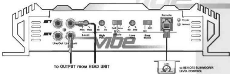
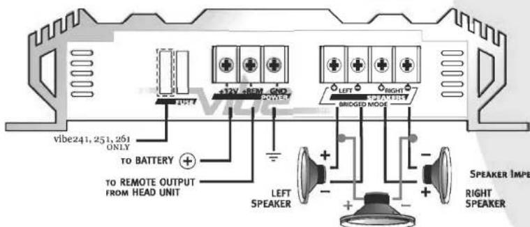
2 CHANNEL STEREO CONFIGURATION
text_image
TO OUTPUT FROM HEAD UNIT From Out List Out Level High Power Mode Low Power Gain Bass Boost Remote Powder Reboot to REMOTE SUBWOOFER LEVEL CONTROL FRONT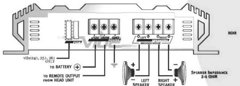
text_image
vibe241, 251, 261 ONLY TO BATTERY + - TO REMOTE OUTPUT FROM HEAD UNIT +12V +REM GND 20Hz RIGHT BRIDGED MODE LEFT RIGHT - - LENT SPEAKER RIGHT SPEAKER SPEAKER IMPEDANCE 2-4 OHM REARLanzar VIBE OWNER'S MANUAL - 7
SYSTEM WIRING
2 CHANNEL BRIDGED MODE CONFIGURATION
vibe211/221/231/241/251/261

text_image
Front to OUTPUT FROM HEAD UNIT TO OUTPUT FROM HEAD UNIT Line Out Unit Level High Power Low Power Low Power Gain Remote Reverter Remote1 12.5V to REMOTE SUBWOOFER LEVEL CONTROL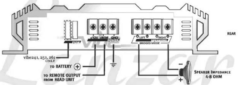
text_image
vibe241, 251, 261 ONLY TO BATTERY + TO REMOTE OUTPUT FROM HEAD UNIT +12V +80V GND POWER BRIDGED MODE LEFT RIGHT SPEAKER IMPEDANCE 4-8 OHM REAR8 - Lanzar VIDE OWNER'S MANUAL
vibe211/221/231/241/251/261
SYSTEM WIRING
2 CHANNEL TRI-MODE CONFIGURATION
text_image
TO OUTPUT FROM HEAD UNIT Level High Full Mode Low Power Boss Reset Remote Power Reset to REMOTE SUBWOOFER LEVEL CONTROLFRONT
text_image
vibe241, 251, 261 ONLY TO BATTERY + TO REMOTE OUTPUT FROM HEAD UNIT +12V +REM GND BRIDGED MODE LEFT RIGHT SPEAKER IMPE RIGHT SPEAKERREAR
SUBWOOFER
Lanzar VIBE OWNER'S MANUAL - 9
SYSTEM WIRING
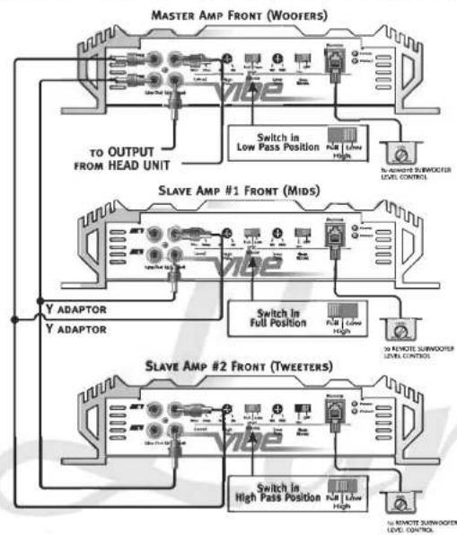
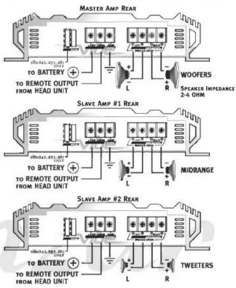
TRIAMP SYSTEM USING THREE 2 CHANNEL AMPLIFIERS
vibe211/221/231/241/251/261
flowchart
graph TD
    A["MASTER AMP FRONT (Woofers)"] --> B["Switch in Low Pass Position"]
    B --> C["30-REMOTE SUBWOOFTER LEVEL CONTROL"]
    D["SLAVE AMP #1 FRONT (Mids)"] --> E["Switch in Full Position"]
    E --> F["30-REMOTE SUBWOOFTER LEVEL CONTROL"]
    G["SLAVE AMP #2 FRONT (Tweeters)"] --> H["Switch in High Pass Position"]
    H --> I["30-REMOTE SUBWOOFER LEVEL CONTROL"]
text_image
MASTER AMP REAR VW(241.251.26) ONLY TO BATTERY + TO REMOTE OUTPUT FROM HEAD UNIT L R WOOFERS SPEAKER IMPEDANCE 2-4 OHM SLAVE AMP #1 REAR VW(241.251.26) ONLY TO BATTERY + TO REMOTE OUTPUT FROM HEAD UNIT L R MIDRANGE SLAVE AMP #2 REAR VW(241.251.26) ONLY TO BATTERY + TO REMOTE OUTPUT FROM HEAD UNIT L R TWEETERS10 - Lanzar VIBE OWNER'S MANUAL
vibe411/421/431
SYSTEM WIRING
4 CHANNEL STEREO CONFIGURATION
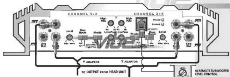
text_image
CHANNEL 1+2 CHANNEL 3+4 Level Bas Boost Mode High Pass Low Pass Low Pass High Pass Power Protects Level Bas Boost Level Power Level Y ADAPTOR Y ADAPTOR TO OUTPUT FROM HEAD UNIT to REMOTE SUBWOORER LEVEL CONTROLFRONT
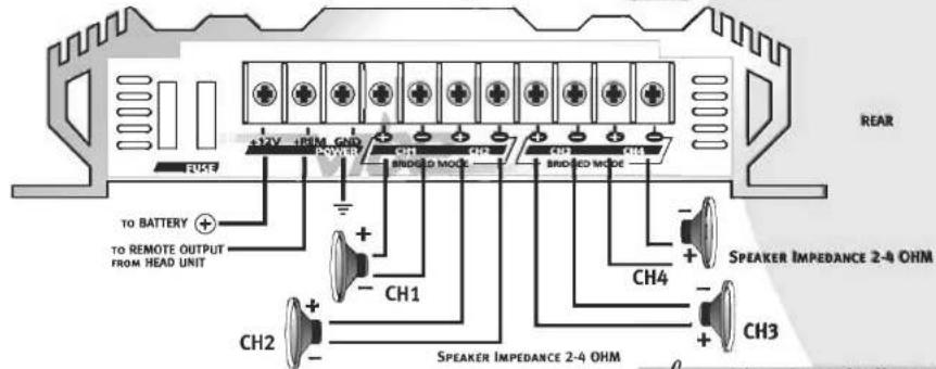
text_image
REAR +32V 18PM GND +45V BRIDLED MODE +45V BRIDLED MODE TO BATTERY + TO REMOTE OUTPUT FROM HEAD UNIT CH1 CH2 CH3 CH4 SPEAKER IMPEDANCE 2-4 OHM SPEAKER IMPEDANCE 2-4 OHMLanzar VIBE OWNER'S MANUAL - 11
SYSTEM WIRING
4 CHANNEL BRIDGED MODE CONFIGURATION
vibe411/421/431
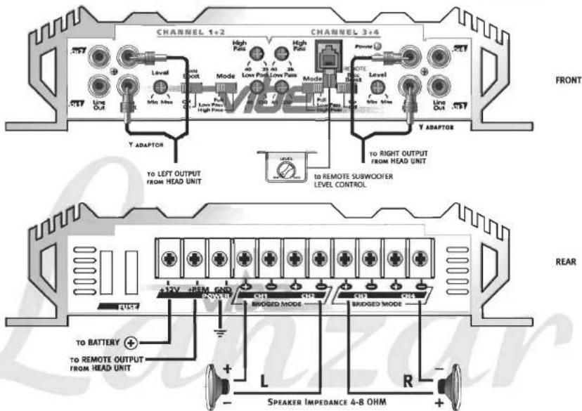
text_image
CHANNEL 1+2 CHANNEL 3+4 High Patio High Patio Level Low Pass Low Pass Mode Low Pass High Pass Power Level Low Pass High Pass Y ADAPTOR TO LEFT OUTPUT FROM HEAD UNIT TO REMOTE SUBWOOFER LEVEL CONTROL FRONT Y ADAPTOR TO RIGHT OUTPUT FROM HEAD UNIT REAR +12V +REF GND BROGGED MODE BROGGED MODE TO BATTERY + TO REMOTE OUTPUT FROM HEAD UNIT L R Speaker Impedance 4-8 OHM12 - Lanzar VIBE OWNER'S MANUAL
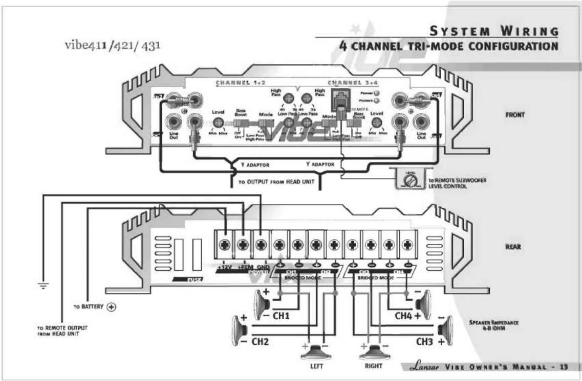
text_image
vibe411/421/431 SYSTEM WIRING 4 CHANNEL TRI-MODE CONFIGURATION CHANNEL 1+2 CHANNEL 3+4 FRONT Level Box Boost High Pass Low Pass Low Pass Mode Power Product Y ADAPTOR Y ADAPTOR TO OUTPUT FROM HEAD UNIT TO BATTERY + TO REMOTE OUTPUT FROM HEAD UNIT BRIDGE MODE BRIDGE MODE BRIDGE MODE BRIDGE MODE BRIDGE MODE BRIDGE MODE BRIDGE MODE BRIDGE MODE BRIDGE MODE BRIDGE MODE BRIDGE MODE BRIDGE MODE BRIDGE MODE BRIDGE MODE BRIDGE MODE BRIDGE MODE BRIDGE MODE BRIDGE MODE BRIDGE MODE BRIDGE MODE BRIDGE MODE BRIDGE MODE BRIDGE MODE BRIDGE MODE BRIDGE MODE BRIDGE Mode BRIDGE Mode BRIDGE Mode BRIDGE Mode BRIDGE Mode BRIDGE Mode BRIDGE Mode BRIDGE Mode BRIDGE Mode BRIDGE Mode BRIDGE Mode BRIDGE Mode BRIDGE Mode BRIDGE Mode BRIDGE Mode BRIDGE Mode BRIDGE Mode BRIDGE Mode BRIDGE Mode BRIDGE Mode BRIDGE Mode BRIDGE Mode BRIDGE Mode BRIDGE Mode BRIDGE Mode BRIDGE MIPEDANCE A-B OHM CH1 CH2 CH3 + LEFT RIGHT LANZAR VIBE OWNER'S MANUAL - 13SYSTEM WIRING
5 CHANNEL STEREO CONFIGURATION
vibe531
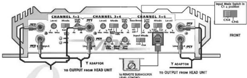
text_image
CHANNEL 1+2 CHANNEL 3+4 CHANNEL 5+6 Input Mode Switch in Ch 4 position CH4 CH6 Level Mode High Pads Level Mode High Pads Rass Boost Low Pads Mode Level Max Max On Off Input Mode CH4 Ch6 Input Y ADAPTOR TO OUTPUT FROM HEAD UNIT Y ADAPTOR TO OUTPUT FROM HEAD UNIT to REMOTE SUBWOOPER LEVEL CONTROL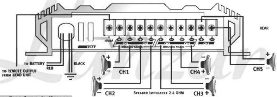
text_image
TO BATTERY RED BLACK +REM CH1 BRIDGED MODE CH2 BRIDGED MODE CH3 CH4 CH5 REAR CH1 CH2 SPEAKER IMPEDANCE 2-4 OHM CH3 +14 - Lanzar VIBE OWNER'S MANUAL
vibe531
SYSTEM WIRING
5 CHANNEL BRIDGED MODE CONFIGURATION
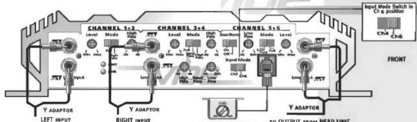
text_image
CHANNEL 1+2 CHANNEL 3+4 CHANNEL 5+6 Level Mode High Pots Level Mode High Pots BassBoost Low Pots Mode Level Input Input Low Pots Input Mode Low Pots Input Mode Y ADAPTOR Y ADAPTOR Y ADAPTOR LEFT INPUT RIGHT INPUT TO OUTPUT FROM HEAD UNIT Input Mode Switch in Ch 6 position CN4 CN6 FRONTto REMOTE SUBWOOFER LEVEL CONTROL
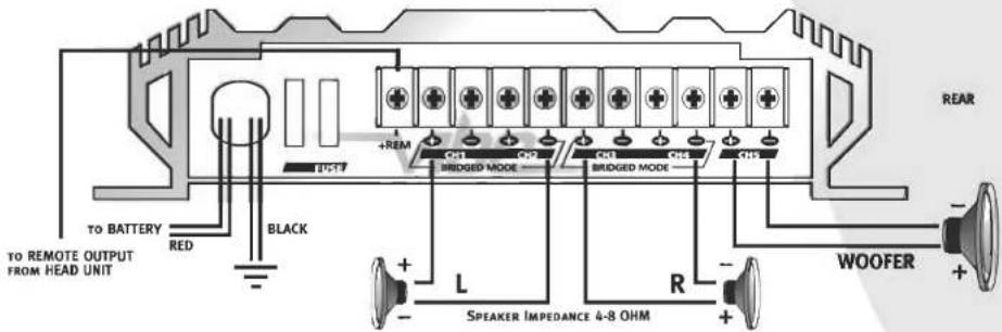
text_image
TO BATTERY RED BLACK +REM BRIDGED MODE BRIDGED MODE L R SPEAKER IMPEDANCE 4-8 OHM REAR WOOFER + - + - - - - - - - - - - - - - - - - - - - - - - - - - - - - - - - - - - - - - - - - - - - - - - - - - - - - - - - - - - - - - - - - - - - - - - - - - - - - - - - - - - - - - - - - - - - - - -Lantar VIBE OWNER'S MANUAL - 15
SYSTEM WIRING
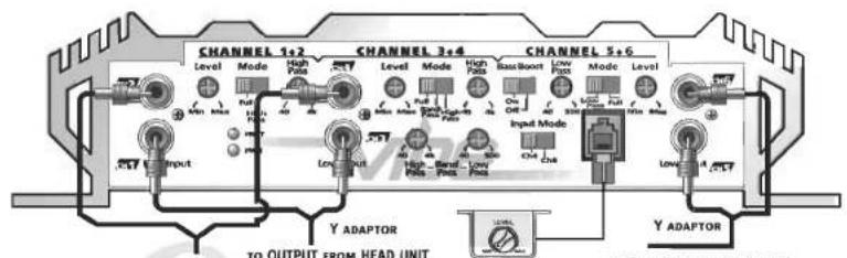
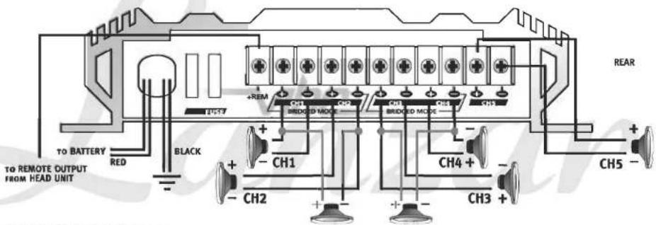
5 CHANNEL TRI-MODE CONFIGURATION
vibe531
text_image
CHANNEL 1+2 CHANNEL 3+4 CHANNEL 5+6 Level Mode High Pads Level Mode High Pads Base Bound Low Pads Mode Level Input Input Low Pads Input Mode Low Pads Low Pads Low Pads Y ADAPTOR TO OUTPUT FROM HEAD UNIT Y ADAPTORFRONT
text_image
TO BATTERY RED BLACK +REM CH1 BRIDDED MODE CH2 CH3 CH4 CH5 REAR TO REMOTE OUTPUT FROM HEAD UNIT CH1 CH2 CH3 CH4 CH516 · Lanzar VIBE OWNER'S MANUAL
TROUBLESHOOTING
AMPLIFIER WILL NOT POWER UP.
- Check for good ground connection.
- Check that remote DC terminal has at least 3v DC.
- Check that there is battery power on the + terminal.
- Check all fuses.
- Check that Protection LED is not lit. If it is lit, shut off amplifier briefly and then repower it.
HIGH MISS OR ENGINE NOISE (ALTERNATOR WHINE) IN SPEAKERS
- Disconnect all RCA inputs to the amplifier(s) – if hiss/noise disappears, then plug in the component driving the amplifier and unplug its inputs. If hiss/noise disappears, go on until the faulty/noisy component is found.
- It is best to set the amplifier's input level as low as possible. The best subjective S/N ratio is obtainable this way. Try to drive as high a signal level from the head unit as possible.
PROTECTION LED COMES ON WHEN THE AMPLIFIER IS POWERED UP.
- Check for shorts on speaker leads.
- Check that the volume control on the head unit is turned down low.
- Remove speaker leads, and reset the amplifier. If the Protection LED still comes on, then the amplifier is faulty.
AMPLIFIER(S) GETS VERY HOT.
- Check that the minimum speaker impedance for that model is correct.
- Check for speaker shorts.
- Check that there is good airflow around the amplifier. In some applications, an external cooling fan may be required.
DISTORTED SOUND
- Check that the Level control(s) is set to match the signal level of the head unit.
- Check that all crossover frequencies have been properly set.
- Check for shorts on the speaker leads.
HIGH SQUEAL NOISE FROM SPEAKERS.
- This is almost always caused by a poorly-grounded RCA patch cord.
Lanzar VIBE OWNER'S MANUAL - 17
