VCT2610 - Empfänger Lanzar - Kostenlose Bedienungsanleitung
Finden Sie kostenlos die Bedienungsanleitung des Geräts VCT2610 Lanzar als PDF.


Benutzerfragen zu VCT2610 Lanzar
0 Frage zu diesem Gerät. Beantworten Sie die, die Sie kennen, oder stellen Sie Ihre eigene.
Eine neue Frage zu diesem Gerät stellen
Laden Sie die Anleitung für Ihr Empfänger kostenlos im PDF-Format! Finden Sie Ihr Handbuch VCT2610 - Lanzar und nehmen Sie Ihr elektronisches Gerät wieder in die Hand. Auf dieser Seite sind alle Dokumente veröffentlicht, die für die Verwendung Ihres Geräts notwendig sind. VCT2610 von der Marke Lanzar.
BEDIENUNGSANLEITUNG VCT2610 Lanzar

text_image
Lanzar® VECTORLanzar Audio Inc. 1600 63rd Street, Brooklyn, NY 11204 (718) 535-1800 www.lanzar.com

text_image
Lanzan® VECTORVCT-2010 VCT-2610 VCT-4110 VCT-15000 VCT-30000
AMERICAN CRAFTED PERFORMANCE
Owner's Manual
www.janzar.com
congratulations...
Congratulations on your purchase of a Lanzar VECTOR series amplifier. You have purchased a quality product designed and engineered to give you many years of uncompromised musical service. VECTOR series amplifiers are designed with the latest technology available, which provides headroom for even the most demanding peaks and dynamic ranges found on modem CDs and recordings.

text_image
LanzarLanzar VECTOR OWNER'S MANUAL
table of contents
| features and specificationsVCT-2010 | 2-3 | stereo/mono input connectionsVCT-2510 | 15-16 |
| features and specificationsVCT-2510 | 4-5 | system wiring speaker connectionsVCT-2010/VCT-2510 | 17 |
| features and specificationsVCT-4110 | 6-7 | Input connectionsVCT-4110 | 18 |
| features and specificationsVCT-5000 | 8-9 | speaker connectionsVCT-4110 | 19 |
| features and specificationsVCT-30000 | 10-11 | mono Input connectionsVCT-5000/VCT-30000 | 20 |
| electrical connectionsVCT-2010/VCT-2510VCT-5000/VCT-30000 | 12 | speaker connectionsVCT-5000/VCT-30000 | 21-23 |
| eo/mono input connectionsVCT-2010 | 13-14 | mounting and installationprotection circuitry and troubleshooting | 24 |
LANDER VECTOR OWNER'S MANUAL - 1
features and specifications
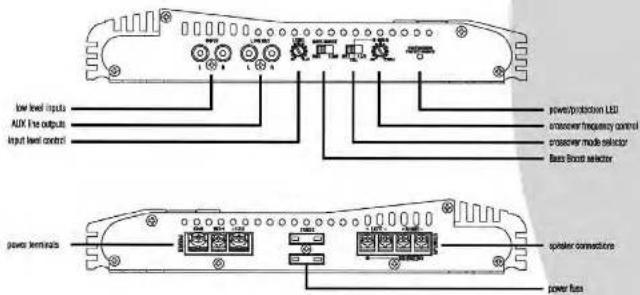
2 ch amp VCT-2010
| crossover mode selector | When used with normal full range system, set this switch to "TUL". If you wish to use the internal crossover to power a driver or specific frequency range, set the L.P. for NPP FOR the LOWPASS OR HIGHPASS settings. | output power 8-14.0K, 30Hz | VCT-2010 |
| MNS Power 6.4 GHz | 35 Watts x 2 | ||
| THD 0.4 GHz | 45 Watts x 2 | ||
| Input level controls | Enable the matching of local levels to the output levels from head unit (or other signal source). The input amplitude of adjustment ranges from 6V to 90Hz. | MNS Power 0.2 GHz | 70 Watts x 2 |
| THD 0.2 GHz | 1/10 Watts x 2 | ||
| crossover frequency control | When crossover mode selector is in HIGHPASS mode, this control sets the lower frequency limit for audio program sets to the speakers. | Maximum Power Output | 800 Watts |
| Bridged Power at 4 Output | 1000 Watts | ||
| Frequency response | 15 Hz-30 KHz | ||
| Input Impezance | |||
| Input level selector | This selector switch periodically the base level an increase of RMB. | Input Impezance | 10K Chms |
| low level input | This encoder has RCA type selector for high impedance input. | Input Impezance | |
| low Level Inputs | 200mV-8V Adjustable | ||
| high level input | Use these with our stereo output which sizes RCA type connector buttons. | 8V radius | >95dB |
| abnormal separation | >55dB | ||
| compressor Filters | |||
| MAX flow inputs | This image contains RCA pointer for AUX line outputs. | Low Power | 40 Hz-250 Hz |
| High Power | 40 Hz-250 Hz | ||
| power LEB | This indicator is shown as in GREEN when power is applied. | Power Level | |
| protective LEB | This indicator is shown as in RGB when the built-in protection continuity is activated. | Amniotic speaker Impezance | 2-4 Chms |
| power fums | The time processes the amplifier and your can's electrical system from short circuit conditions. | amniotic mode | 4-8 Chms |
| bridged mode | |||
| power terminals | Use these connections to deliver power, ground, and remote turn-out control in the amplifier. | maximum current dose | 20K x 2 |
| power supply voltage | 14-4V DC Neg. Ground (10.5-16V) | ||
| speaker connectors | These terminals are to guarantee high overactivity and maximum signal loss. | disinhibition (W & I) U | 270 x 45.2 x 190 |
| buschex | 10.63 x 1.78 x 7.49 |

features and controls
2 ch amp VCT-2010
text_image
low level inputs AUX line outputs Input level control power/protective LED crossover frequency control crossover mode selector Base Bracket selector power terminals speaker connections power bus
features and specifications
2 ch amp VCT-2610
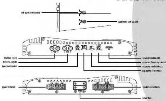
| cransscrew mode selector | When used with nominal, full range system, set this switch to TOU 1"If we switch to use the internal crossover to power a driver or specific frequency range, on the LTR of "HAPP" ION for the audio input. | output power 14.4 Hz, 1KHz | VCT-2010300 Watts x 2 |
| RNG Power 4 Ohms | 450 Watts x 2 | ||
| THD 4 Ohms | 800 Watts x 2 | ||
| RNG Power 2 Ohms | 900 Watts x 2 | ||
| THD 4 Ohms | 9000 Watts | ||
| INPUT level controls | The output capacity of adjustment ranges from BT to SB | Maximum Power Output | |
| transfer frequency control | When a transscrew mode selector is in HASAPASS made this control and let the lower frequency find for audio program set to the speakers. | Output Power of 4 Output | 9000 Watts |
| Frequency response | 15 Hz-30 KHz | ||
| Input Impedance | |||
| low Level inputs | 10K Ohms | ||
| base level control | When a transscrew mode selector is in HASAPASS made this control and let the upper frequency find for audio program set to the speakers. | Input Impactability | |
| low Level inputs | |||
| low Level outputs | |||
| Sub active control | The output capacity adjustment from 40 to 250 Hz. | 200mV-5V Adjustable | |
| approximately 10 Hz. | >25dB | ||
| at maximum separate | >65dB | ||
| low level input | at maximum filter | >65dB | |
| high level input | The only features RGA type pins for high impedance input. | at low levels | |
| at low levels output | |||
| low Power | 40 Hz-250 Hz | ||
| High Power | 40 Hz-250 Hz | ||
| low Power | 9 - 18dB | ||
| at low level | 10-100 Hz | ||
| AXL time output | The only features RGA type pins for AUX line outputs. | at low levels | |
| at low levels output | |||
| at low levels output | |||
| at low levels output | |||
| at low levels output | |||
| at low levels output | |||
| at low levels output | |||
| at low levels output | |||
| at low levels output | |||
| at low levels output | |||
| at low levels output | |||
| at low levels input | |||
| at low levels input | |||
| at low levels input | |||
| at low levels input | |||
| at low levels input | |||
| at low levels input | |||
| at low levels input | |||
| at low levels input | |||
| at low levels input | |||
| at low levels input | |||
| at low levels output | |||
| at low levels output | |||
| at low levels output | |||
| at low levels output | |||
| at low levels output | |||
| at low levels output | |||
| at low levels output | |||
| at low levels output | |||
| at low levels output | |||
| at low levels输出 | |||
| at low levels output | |||
| at low levels output | |||
| at low levels output | |||
| at low levels output | |||
| at low levels output | |||
| at low levels output | |||
| at low levels output | |||
| at low levels output | |||
| at low levels output | |||
| at low levels outputs | |||
| at low levels outputs | |||
| at low levels outputs | |||
| at low levels outputs | |||
| at low levels outputs | |||
| at low levels outputs | |||
| at low levels outputs | |||
| at low levels outputs | |||
| at low levels outputs | |||
| at low levels outputs | |||
| at low levels output | |||
| at low levels output | |||
| at low levels output | |||
| at low levels output | |||
| at low levels output | |||
| at low levels output | |||
| at low levels output | |||
| at low levels output | |||
| at low levels output | |||
| at low levelsOutput | |||
| at low levels Output | |||
| at low levels Output | |||
| at low levels Output | |||
| at low levels Output | |||
| at low levels Output | |||
| at low levels Output | |||
| at low levels Output | |||
| at low levels Output | |||
| at low levels Output | |||
| at low levels Output | |||
| at low levelsOutput | |||
| at low levels Output | |||
| at low levels Output | |||
| at low levels Output | |||
| at low levels Output | |||
| at low levels Output | |||
| at low levels Output | |||
| at low levels Output | |||
| at low levels Output | |||
| at low levelsOutput | |||
| at low levelsOutput | |||
| at low levelsOutput | |||
| at low levelsOutput | |||
| at low levelsOutput | |||
| at low levelsOutput | |||
| at low levelsOutput | |||
| at low levelsOutput | |||
| at low levelsOutput | |||
| at low levelsOutput | |||
| at low levels Output | |||
| at low levels Output | |||
| at low levels Output | |||
| at low levels Output | |||
| at low levels Output | |||
| at low levels Output | |||
| at low levels Output | |||
| at low levels Output | |||
| at low levels Input | |||
| at low levels Input | |||
| at low levels Input | |||
| at low levels Input | |||
| at low levels Input | |||
| at low levels Input | |||
| at low levels Input | |||
| at low levels Input | |||
| at low levels Input | |||
| at low levels Input | |||
| at low levels Output | |||
| at low levels Output | |||
| at low levels Output | |||
| at low levels Output | |||
| at low levels Output | |||
| at low levels Output | |||
| at low levels Output | |||
| at low levels Output | |||
| at low levels Output | |||
| at low levels Input | |||
| at low levels Output | |||
| at low levels Output | |||
| at low levels Output | |||
| at low levels Output | |||
| at low levels Output | |||
| at low levels Output | |||
| at low levels Output | |||
| at low levels Output | |||
| at low levels Input | |||
| at low levelsOutput | |||
| at low levelsOutput | |||
| at low levelsOutput | |||
| at low levelsOutput | |||
| at low levelsOutput | |||
| at low levelsOutput | |||
| at low levelsOutput | |||
| at low levelsOutput | |||
| at low levelsOutput | |||
| at low levelsInput | |||
| at low levelsInput | |||
| at low levelsInput | |||
| at low levelsInput | |||
| at low levelsInput | |||
| at low levelsInput | |||
| at low levelsInput | |||
| at low levelsInput | |||
| at low levelsInput | |||
| at low levelsInput | |||
| at low levelsOutput | |||
| at low levelsOutput | |||
| at low levelsOutput | |||
| at low levelsOutput | |||
| at low levelsOutput | |||
| at low levelsOutput | |||
| at low levelsOutput | |||
| at low levelsOutput | |||
| at low levelsOutput | |||
| at low levelsSupply | |||
| at low levelsOutput | |||
| at low levelsOutput | |||
| at low levelsOutput | |||
| at low levelsOutput | |||
| at low levelsOutput | |||
| at low levelsOutput | |||
| at low levelsOutput | |||
| at low levelsOutput | |||
| at low levelsOutput | |||
| at low levelsActual | |||
| at low levelsOutput | |||
| at low levelsOutput | |||
| at low levelsOutput | |||
| at low levelsOutput | |||
| at low levelsOutput | |||
| at low levelsOutput | |||
| at low levelsOutput | |||
| at low levelsOutput | |||
| at low levelsOutput | |||
| at low levelsCurrent | |||
| at low levelsCurrent | |||
| at low levelsCurrent | |||
| at low levelsCurrent | |||
| at low levelsCurrent | |||
| at low levelsCurrent | |||
| at low levelsCurrent | |||
| at low levelsCurrent | |||
| at low levelsCurrent | |||
| at low levelsCurrent | |||
| at low levelsOutput | |||
| at low levelsOutput | |||
| at low levelsOutput | |||
| at low levelsOutput | |||
| at low levelsOutput | |||
| at low levelsOutput | |||
| at low levelsOutput | |||
| at low levelsOutput | |||
| at low levelsOutput | |||
| at low levelsPower | |||
| at low levelsOutput | |||
| at low levelsOutput | |||
| at low levelsOutput | |||
| at low levelsOutput | |||
| at low levelsOutput | |||
| at low levelsOutput | |||
| at low levelsOutput | |||
| at low levelsOutput | |||
| at low levelsOutput | |||
| at low levelsControl | |||
| at low levelsControl | |||
| at low levelsControl | |||
| at low levelsControl | |||
| at low levelsControl | |||
| at low levelsControl | |||
| at low levelsControl | |||
| at low levelsControl | |||
| at low levelsControl | |||
| at low levelsControl | |||
| at low levelsOutput | |||
| at low levelsOutput | |||
| at low levelsOutput | |||
| at low levelsOutput | |||
| at low levelsOutput | |||
| at low levelsOutput | |||
| at low levelsOutput | |||
| at low levelsOutput | |||
| at low levelsOutput | |||
| at low levelsActive | |||
| at low levelsOutput | |||
| at low levelsOutput | |||
| at low levelsOutput | |||
| at low levelsOutput | |||
| at low levelsOutput | |||
| at low levelsOutput | |||
| at low levelsOutput | |||
| at low levelsOutput | |||
| at low levelsOutput | |||
| at low levelsTotal | |||
| at low levelsOutput | |||
| at low levelsOutput | |||
| at low levelsOutput | |||
| at low levelsOutput | |||
| at low levelsOutput | |||
| at low levelsOutput | |||
| at low levelsOutput | |||
| at low levelsOutput | |||
| at low levelsOutput | |||
| at low levelsOut |

VECTOR OWNER'S MANUAL - 4
features and controls
2 ch amp VCT-2610
text_image
sub sink level control low level inputs AUX line outputs Input level control xus boost level control power/production LED conversion frequency control crossover mode selector sub sink filter switch power terminals speaker connections power bus
VECTOR OWNER'S MANUAL - 3
features and specifications
4 ch amp VCT-4110
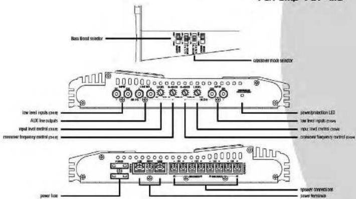
| amower mode selector | When rated with normal, full range system, set this switch to '10.1." If we wish to use the internal crossover to power a driver or specific frequency range, one of the 12"Hz for "TWP" (100 Hz to H2/4/4/5/6/7) | output power: 14.4V DC, 1Hz | VST-11D |
| RWD Power @ 4 Ohms | 50 Waits x 4 | ||
| THD @ 4 Ohms | 75 Waits x 4 | ||
| level level selective | Enable the matching of level input by the output lines from hand load (for either signal source). The input capacity of adjustment ranges from 8V to 300Hz. | RWD Power @ 2 Ohms | 100 Waits x 4 |
| THD @ 2 Ohms | 150 Waits x 4 | ||
| power frequency constant | When an amower mode selector is in H2/4/4/5/6/7 mode this control set into the lower frequency limit for audio program set to the speakers. When amower mode selector is in CLO/4/4/5/6/7 mode this control set by the upper frequency limit for audio program set to the speakers. The nominal is electrically variable adjustment from 40 to 250 Hz. | Maximum Power Output | 2000 Waits |
| Output Power at 4 Output | 4000 Waits | ||
| house based level constant | This nominal permits adjustment of the base level up to an increase of approximately up to 1600Hz. | Frequency capacitor | 15 Hz to 30 Hz |
| Input Impedance | |||
| low Level Inputpe | 10K Ohms | ||
| Input Efficiency | |||
| low level input | The input voltage plate type sets for high experience request. | low Level Inputpe | 200mV~8V Adjustable |
| High Level Inputpe | >35dB | ||
| high level input | Use these with car stored output which sets RCA type connector switches. | disassembled performance | >45dB |
| disassembled filters | |||
| If your car stresse sets out the RCA type output, and the high-level signal outputs are continued the speaker output leads of car stones and the RCA slot jacks of amps. | low Pass | 40 Hz to 250 Hz | |
| high Pass | 40 Hz to 250 Hz | ||
| AXS line segments | Util any requires RCA slots for AUX low output. | matching speaker Impedance | |
| Use these for unskilled speaker也可以 to the next VECTOR. | storage mode | 2-16 Ohms | |
| power LBS | The output is illuminated on DLET when power is applied. | storage mode | 4-16 Ohms |
| protection LBS | The indicator is thresholded in REP when the back in creation closely is required. | system mode | |
| power base | The base protects the amplifier and your car electronic systems from short circuit conditions. | system mode | 2-16 Ohms |
| power terminals | Use these connectors to deliver power, ground, and remote turn-on control to the amplifier. | system mode | 4-16 Ohms |
| speaker connections | Three terminals are to guarantee high conductivity and microwave signal level. | maximum current dose | 33A x 2 |
| power supply voltage | 14.4V DC Neg. Ground (10.5-16V) | ||
| demonstration (V×1×1) | |||
| min | 270 x 43.2 x 320 | ||
| inches | 10.63 x 1.78 x 14.02 |

features and controls
4 ch amp VCT-4110
text_image
Base Broad selector crossover mode selector low level inputs power AUX line output input level control power corrosion frequency control power power/protection LED low level inputs power input level control power corrosion frequency control power power bus tosphor connected out power terminals
features and specifications
I ch amp VCT-1500D
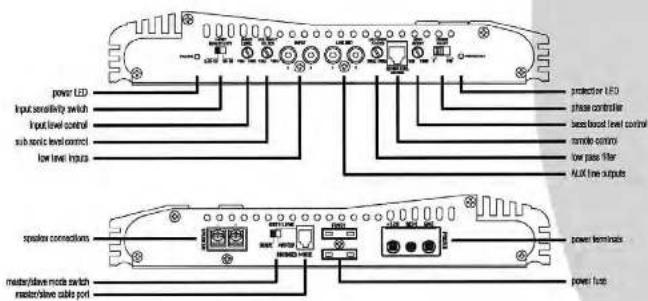
| Input level control | Enables the matching of input levels to the output levels from hard and (or other signal output). | output power 14.4V DC, 1Hz | VCT-15000 |
| Input level control | This control permits adjustment of the base level up to an increase of approximately up to 1dB. | RND Power 4 GHz | 300 Watts x 1 |
| THD 4 GHz | 450 Watts x 1 | ||
| low basic control | Unstable adjustment from 15 to 4GHz. | RND Power 2 GHz | 450 Watts x 1 |
| low level input | The arc repeats RCA type jacks for high impedance input. | THD 8 GHz | 650 Watts x 1 |
| Use these with car stereo output which also uses RCA type connector cables. | RND Power 1 GHz | 300 Watts x 1 | |
| Input sensitivity | The least complexity of adcomerators is 100% up to 4V to 200V. | MPA up to 1000 Watts x 1 | 1000 Watts x 1 |
| low power filter | Variable adjustment from 50 to 150Hz. | Marathon Power Output | 1500 Watts x 1 |
| remote control | Adjust the low pulse signal via the enclosed remote controller. | frequency response | 15 Hz-150 Hz |
| plane sensitivity | SMT shows 0 degree 7Hz degrees. | Input impedance | |
| AIDS data output | The arc repeats RCA jacks or AUX line outputs. | low level inputs | 10K Ohms |
| input sensitivity | 0.2V-4V | ||
| low level inputs | 200mV-5V Adjustable | ||
| power LED | Live laser for unlimited operation operation to the next VDD/ON. | >5dB | |
| The indicator is illuminated in DLEAV when power is applied. | channel sequence | >5dB | |
| protection LED | The indicator is illuminated in RSD when the built-in production circuit is activated. | crossover filters | |
| maskhole mode part | MASTER/PLA/S signal cable. | low Pass | 50 Hz-150 Hz |
| maskhole mode module | In the SLA/C-steady low amplifier works on a SLA/C arc, this means only the audiovisual of the SLA/C arc will be amplified. | boxy button | 0 ~ 1dB |
| All conductors on the SLA/C arc are without function and will be assumed by the MASTER arc. | boxy mode filter | 15-40 Hz | |
| In the SLA/C-mode Low flux mode you are able to shift the frequencies to allow with the Low RMS controls. All components are active. | matching operator impedance | ||
| power from | The fuse protects the amplifier and your ear's electric system from short circuit conditions. | strome mode | 2.8 Ohms |
| brigued mode | 1-6 Ohms | ||
| power torque | Use these connectors to deliver power, ground, and remote turn-on control to the amplitude. | maximum current draw | 300 x 2 |
| power supply voltage | 14.4V DC Neg. Ground (10.5-16V) | ||
| speaker structure | These terminals are to guarantee high conductivity and minimum signal use. | dissimation (W × 1 L) | |
| non | 270 x 45.2 x 306 | ||
| inches | 10.83 x 1.78 x 12.13 |

features and controls
I ch amp VCT-15000
text_image
power LED Input sensitivity switch Input level control such boric level control low level inputs protector LED phase controller band based level control remote control low pass filter ALUX line outputs speaker connections master/dlave mode switch master/dlave cable port power terminals power fuses
features and specifications
I ch amp VCT-3000D
| Input level control | Enables the matching of input levels to the output levels from hard and (or other signal output). | output power 16.4kV DC, 1Hz | VCT-35000 |
| Line based level control | The control permits adjustment of the base level up to an increase of approximately up to 1dB. | RND Power 4 Ohms | 500 Watts x 1 |
| THD 4 Ohms | 650 Watts x 1 | ||
| low basic control | Unstable adjustment from 15 to 4MHz | RND Power 0 Ohms | 550 Watts x 1 |
| low level input | The arc repeats RGA type jacks for high impedance input. | THD 8 Ohms | 800 Watts x 1 |
| Use these with car arrows output which area RGA type connector cables. | RND Power 0 Ohms | 1000 Watts x 1 | |
| load sensitivity | The load capacitance of adornment from 10V to 4V to 200mV. | TWD up to 1GHz | 2000 Watts x 1 |
| low power filter | Variable adjustment from 50 to 150Hz. | Marathon Power 3000 Watts x 1 | 3000 Watts x 1 |
| residual control | Adjust the low pass signal to the enclosed records output. | Frequency response | |
| phone sensitivity | SNT shows 0 degree THD degrees. | Input impedance | |
| AIDS data output | The arc repeats RGA jacks or AUX line outputs. | low level inputs | 15 Hz-150 Hz |
| Live laser for unlimited operation separation to the next I/O/DN. | input sensitivity | 10K Ohms | |
| power LED | The indicator is illuminated on DHLAM when power is applied. | Input sensitivity | 0.2V-4V |
| protection LED | The indicator is illuminated on RSD when the built-in production circuit is activated. | low level inputs | 200mV-5V Adjustable |
| nominal/above nominal part | MASTER/CLAV/SNS signal cables. | 300 ohms | >50dB |
| nominal/above nominal output | In the CLAV-3000 low electric words on a LLAV arc, this means only the audiovisual of the MASTER arc but not be amplified. | channel separation crossover filters | >50dB |
| All conductors on the SLAV arc are without function and will be assumed by the MASTER arc. | low Pass | 50 Hz-150 Hz | |
| In the LLAV-3000 mode: Low pass modes you are able to shift the frequencies to above with the Low RSS controls. All conductors are active. | load power | 0 ~ 18dB | |
| power from | The fuse protects the amplifier and your ear's electrical system from short circuit conditions. | with some filter matching operator impedance | 15-40 Hz |
| power terminal | Use these connectors to deliver power, ground, and remote turn-on control to the amplifier. | store mode | 2.8 Ohms |
| speaker structure | These terminals are to guarantee high conductivity and maximum signal loss. | brigued mode maximum current draw | 1-6 Ohms |
| power supply voltage differences (W × 1 V) | 14.4V DC Neg. Ground (10.5-16V) | ||
| non inches | 270 x 45.2 x 360 | ||
| 10.83 x 1.78 x 14.17 | |||
Lancor VECTOR OWNER'S MANUAL - 10
features and controls
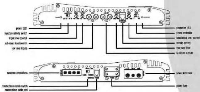
I ch amp VCT-30000
text_image
power LED Input sensitivity switch Input level control Sub haptic level control Low level Inputs protector LED phase controller band base level control remote output low pass filter ALK line outputs speaker connections master/leave mode switch master/leave cable port power terminals power fusesLancor VECTOR OWNER'S MANUAL - 11
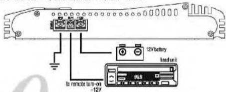
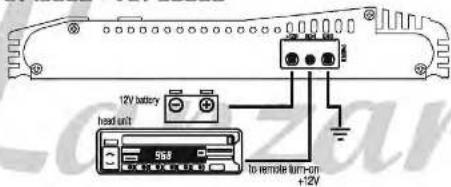
electrical connections
VCT-2010 · VCT-2610 · VCT-4110
text_image
12V battery load unit to remote turn-on -12VVCT-15000 · VCT-30000
text_image
12V battery head unit 56A to remote turn-on +12VLancor VECTOR OWNER'S MANUAL - 12
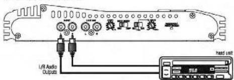
stereo input connections
2 ch amp · VCT-2010
using low level inputs
text_image
I/R Audio Outputs head unitusing high level inputs
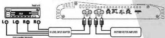
text_image
head unit L+ L- R- R+ from speaker terminals IN LEVEL INPUT ADAPTER ANOTHER VECTOR AMPLIFIERL. Linear VECTOR OWNER'S MANUAL - 13
mono input connections
2 ch amp · VCT-2010
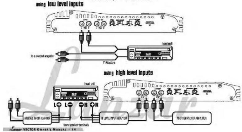
text_image
using low level inputs To a second amplifier Y Adaptors used unit used unit used unit used unit used unit used unit used unit used unit used unit used unit used unit used unit used unit used unit used unit used unit used unit used unit used unit used unit used unit used unit used unit used unit used unit used unit used unit used unit used unit used unit used unit used unit used unit used unitstereo input connections
2 ch amp · VCT-2610
using low level inputs
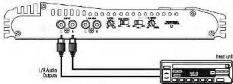
text_image
L/R Audio Outputs head unit 36.0using high level inputs
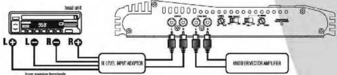
text_image
360 L+ L- R- R+ H LEVEL INPUT ADAPTOR ANDI-SERVED AMPLIFIER Type speaker terminalsL. MANOUR VECTOR OWNER'S MANUAL - TS
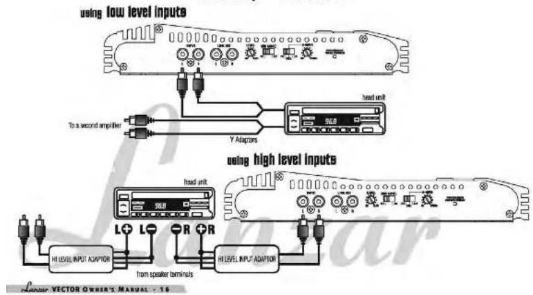
mono input connections
2 ch amp · VCT-2610
text_image
using low level inputs To a second amplifier Y Adaptors used unit used high level inputs head unit L+ L- R+ R HI LEVEL INPUT ADAPTOR from speaker terminals HI LEVEL INPUT ADAPTOR Linear VECTOR OWNER'S MANUAL - 1.6speaker connections
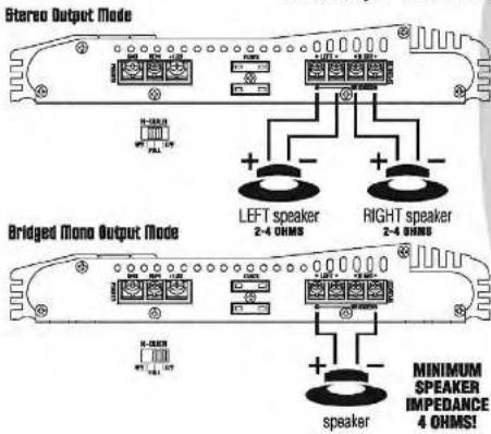
2 ch amp · VCT-2010 · VCT-2610
text_image
Stereo Output Mode Bridged Mono Output Mode LEFT speaker 2-4 OHMS RIGHT speaker 2-4 OHMS MINIMUM SPEAKER IMPEDANCE 4 OHMS! speakerL. Linear VECTOR OWNER'S MANUAL - 12
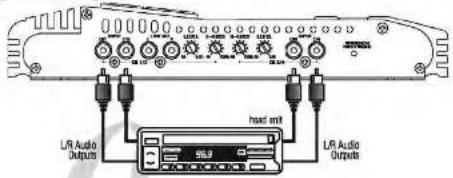
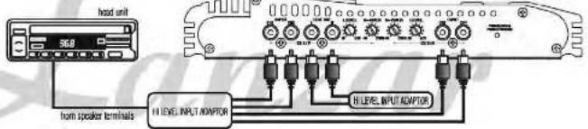
input connections
4 ch amp VCT-4110
using low level inputs
text_image
LR Audio Outputs head unit LR Audio Outputsusing high level inputs
text_image
head unit 50.0 from speaker terminals H LEVEL INPUT ADAPTER H LEVEL INPUT ADAPTERL. VECTOR OWNER'S MANUAL - 18
speaker connections
4-Channel Mode
4 ch amp VCT-4110
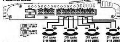
text_image
CN 3-4 0-000V 1/1/2 CN 3-4 0-000V 1/1/2 CN 3-4 0-000V 1/1/2 CN 3-4 0-000V 1/1/2 CN 3-4 0-000V 1/1/2 CN 3-4 0-000V 1/1/2 CN 3-5 0-000V 1/1/2 CN 3-5 0-000V 1/1/2 CN 3-5 0-000V 1/1/2 CN 3-5 0-000V 1/1/2 CN 3-5 0-000V 1/1/2 CN 3-5 0-01 0-01 0-1 CN 3-5 0-1/2 CN 3-5 0-1/2 CN 3-5 0-1/2 CN 3-5 0-1/2 CN 3-5 0-1/2 CN 3-5 0-1/2 CN 3-5 0-1/2 CN 3-5 0-1/2 CN 3-5 0-1/2 CN 4-5 0-1/2 CN 4-5 0-1/2 CN 4-5 0-1/2 CN 4-5 0-1/2 CN 4-5 0-1/2 CN 4-5 0-1/2 CN 4-5 0-1/2 CN 4-5 0-1/2 CN 4-5 C#1 speaker 2-18 CMNS C#2 speaker 2-18 CMNS C#3 speaker 2-18 CMNS C#4 speaker 2-18 CMNS3-Channel Mode
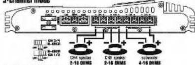
text_image
CHM 3/4 CHM 2-10 DRMS CHR 2-10 DRMS CHM 3/4 CHM 2-10 DRMS CHR 2-10 DRMS CHM 3/4 CHM 2-10 DRMS CHR 2-10 DRMS CHM 3/4 CHM 2-10 DRMS CHR 2-10 DRMS CHM 3/4 CHM 2-10 DRMS CHD 3/4 CHD 2-10 DRMS CHD 2-10 DRMS CHD 3/4 CHD 2-10 DRMS CHD 2-10 DRMS CHD 3/4 CHD 2-10 DRMS CHD 2-10 DRMS CHD 3/4 CHD 2-10 DRMS CHD 2-10 DRMS CHD 3/4 CHD 3/4 CHD 2-10 DRMS CHD 2-10 DRMS CHD 3/4 CHD 2-10 DRMS CHD 2-10 DRMS CHD 3/4 CHD 3/4 CHD 2-10 DRMS CHD 2-10 DRMS CHD 3/4 CHD 3/4 CHD 2-10 DRMS CHD 2-10 DRMS CHD 3/4 CHD 3/4 CHD 2-10 DRMS CHD 2-10 DRMS CHD 2-10 DRMS CHD 3/4 CHD 3/4 CHD 2-10 DRMS CHD 2-10 DRMS CHD 2-10 DRMS CHD 3/4 CHD 3/4 CHD 2-10 DRMS CHD 2-10 DRMS Chrombors Chrombors Chrombors ChromborsBridged Mono Mode
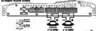
text_image
I/O 3/4 I/O 1/2 I/O 4-16 防接器 I/O 4-18 防接器VECTOR OWNER'S MANUAL - 19
mono input connections
I ch amp VCT-15000 · VCT-30000
Interconnection Low Pass-Mode
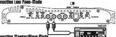
text_image
Section Low Pass-Mode Connection Master/Slave ModeInterconnection Master/Slave Mode
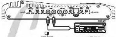
text_image
Diagram of an electronic device rear panel with labeled ports and connection points, including a control interface and indicator lights.Master
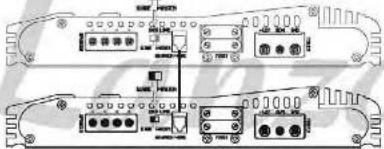
text_image
Technical diagram of a dual-chamber electronic device with labeled ports and connectorsSlave
Lancor VECTOR OWNER'S MANUAL - 20
speaker connections
I ch amp VCT-1500D · VCT-3000D
Interconnection Low Pass-Mode
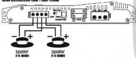
text_image
MEMSOMETER 2.0 MHz MODE Speaker 2-8 DIMS Speaker 2-8 DIMS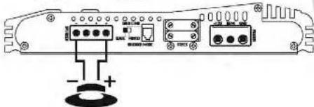
text_image
Diagram of an electronic device rear panel with labeled ports and connectors, including a battery icon and indicator lights.speaker 1-8 OHMS
VECTOR OWNER'S MANUAL - 21
speaker connections
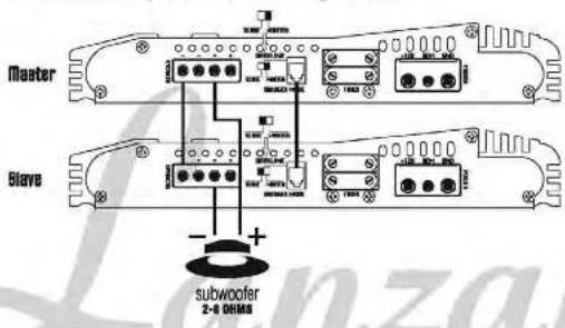
I ch amp VCT-1500D · VCT-3000D
Interconnection Master/Slave Mode
Interconnection example 1 subwoofer with a single-Voicscoil
text_image
Master Slave + - subwoofer 2-8 OHMSLancier VECTOR OWNER'S MANUAL - 22
speaker connections
I ch amp VCT-1500D · VCT-3000D
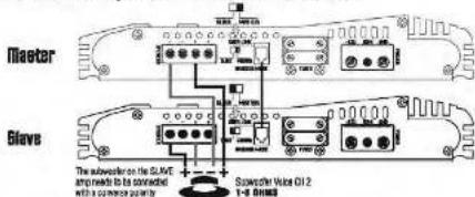
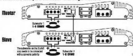
Interconnection Master/Slave Mode
Interconnection example 1 subwooPer with a Dual-Voicecoll
text_image
Master Sloves The suboperator on the Slave and needs to be connected with a connection priority Spencer: Vise Oil2 1-8 SlavicInterconnection example 2 subwooPer with Single-Voicecoli
text_image
Master Slave The power switch on the SUATE amp needs to be connected with a concrete pelvis Substrate 1 1-0 GMSB Substrate 2 1-0 GMSBVECTOR OWNER'S MANUAL - 23
mounting and installation
mounting Your new customer's four-year
Your new Lanzar Vector Series amplifier comes complete with all required mounting hardware. When determining a suitable location in your vehicle for the amp, please remember that it is a high-power electronic device capable of generating high heat.
For this reason, always choose a location in your vehicle which has low vibration, adequate ventilation, a minimum of dust, and no moisture. Be sure to mount the amp in such a manner as to allow reasonable airflow over the cooling fins
Mark the location for the mounting screw holes by positioning the amp where you wish to install it and use a scribe (or one of the mounting screws) inserted in each of the mounting holes to mark the mounting surface. If the mounting surface is carpeted, measure the hole carriers and mark with a felt tip pen.
Before attempting to drill the mounting holes, take note of any wires, lines or other devices in your vehicle which may be located behind the mounting surface! Then drill pilot holes in the mounting surface for the mounting screws and insert them. Tighten the screws securely.
When making electrical connections to your amplifier, please observe the following:
Use at least 3 gauge wire for power and ground connections.
Wire the amplifier directly to the car battery
For the ground connection, use the shortest possible wire to a good chassis's ground point.
Wire the Remote connection to the auto start lead of your head unit, equalizer or power antenna.
About power fuses:
Lanzar Vector Series amplifiers feature built-in fuse systems. These fuses protect both the amplifier and the electrical system in your vehicle from fault conditions. If you ever need to replace the fuse in your Lanzar Vector Series amp, use a fuse of exactly the same type and rating. A different type or rating of fuse may result in damage or fire.

VECTOR OWNER'S MANUAL - 24
troubleshooting
protection circuitry
The built-in protection circuitry in the Lanzer Vector Series amplifiers will disable the amplifier if it senses an input overload, a speaker short circuit, or extreme temperature conditions.
When the protection circuit is activated by any of these conditions, the Protection LED will be illuminated.
If this occurs, carefully inspect the system to determine the source of the problem.
- If the shutdown was a result of a thermal overload condition, allow the amplifier to cool down before attempting to restart it.
- If the shutdown was a result of an input overload, or speaker short circuit, be sure to correct the condition before restarting.
The amplifier can be restarted by turning the remote power OFF and then ON again.
He outper
Confirm that all terminal strip connections are secure and light.
Check both In-line and built-in fuses. Both the +12V and the Remote terminals must have +12V referenced to chassis ground.
Confirm that the audio signal source (car radio, equator, etc.) is connected and is supplying output signal. To check if the amp is supplying signal, unplug the cables from the signal source (but have them plugged into the amp). Briefly tap the center pin of each of the disconnected RCA plugs with your finger. This should produce a noise (feedback) in your speakers.
Only one channel works.
Confirm that all terminal strip connections are secure and tight.
Check the Balance control on the head unit (or other source) to verify that it is set to its midpoint.
If you are using the Low Level PCA input, reverse the input plugs at the amplifier (i.e., switch the L with the R). If the channels which is silent switches to the other side, the problem is either in the head unit/other source or the connecting cables.
Weak output.
Readjust the Input Level Control(s) to better suit the input signal.
Helios in the audio.
If the noise is a "white" whose pitch follows the engine speed, confirm that the amplifier and any other signal sources (lead unit, etc.) are properly grounded.
If the noise is a "clicking" or "pooping" noise whose rate follows the engine speed, this usually means that the vehicle is equipped with resistor spark plugs and wires, or that the ignition is in need of service.
Check the rounding of the speaker and input wires to make sure they are not adjacent to wires which interconnect lights and other accessories.
If the above steps fall to improve or clear noise interference, the system should be checked by a professional mobile audio installer.
Lancor VECTOR OWNER'S MANUAL - 25
precautions
Do not operate the amplifier when it is unmounted. Attach all audio system components securely within the automobile to prevent damage, especially in an accident.
Do not mount this amplifier so that the wire connections are unprotected, or in a pinched condition, or likely to be damaged by nearby objects.
Before making or breaking power connections in your system, disconnect the vehicle battery. Confirm that your head unit or other equipment is turned off while connecting the input jacks and speaker terminals.
If you need to replace the power fuse, do so only with a fuse identical to that supplied with the amplifier. Using a fuse of a different type or rating may result in damage that isn't covered in the manufacturer's warranty.
text_image
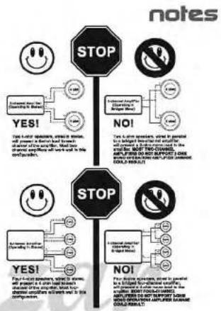
notes STOP YES! Four 4-00 speeds, which is slow, will prevent the accident. When the accident is caused, what will be repeated correctly to avoid it in the compounds. NO! Four 4-00 speeds, which is slow, will prevent the accident. When the accident is caused, what will be repeated correctly to avoid it in the compounds. NO! Four 4-00 speeds, which is slow, will prevent the accident. When the accident is caused, what will be repeated correctly to avoid it in the compounds. NO! Four 4-00 speeds, which is slow, will prevent the accident. When the accident is caused, what will be repeated correctly to avoid it in the compounds.Lemon VECTOR OWNER'S MANUAL - 26