
EVB-BA100 - Detektor BOSCH - Kostenlose Bedienungsanleitung
Finden Sie kostenlos die Bedienungsanleitung des Geräts EVB-BA100 BOSCH als PDF.


| Produkttyp | Backup-Audio-Schnittstelle (Detektor) |
| Modell | EVB-BA100 |
| Marke | Bosch |
| Spannungsversorgung | 24 V DC |
| Stromverbrauch Standby | 40 mA |
| Stromverbrauch Aktiv | 10 mA |
| Audio-Signal-Kompatibilität | 25 VRMS und 70 VRMS |
| Montage | Snap-Track oder Isolierabstandshalter |
| Anschlussklemmen | TB1 (Lautsprecher), TB2 (Verstärkereingänge), TS1 (Steuerung/Spannung) |
| LED-Anzeige | Leuchtet bei zugeschaltetem Backup-Verstärker |
| Verdrahtung | Power-limited |
| Kabelquerschnitte | 6-32: 14-18 AWG, 8-32: 12-18 AWG, Horizontal: 18-26 AWG |
| Ersatz für | EVX-BA |
| Funktion | Automatische Umschaltung auf Backup-Verstärker bei Ausfall des Primärverstärkers |
Häufig gestellte Fragen - EVB-BA100 BOSCH
Benutzerfragen zu EVB-BA100 BOSCH
0 Frage zu diesem Gerät. Beantworten Sie die, die Sie kennen, oder stellen Sie Ihre eigene.
Eine neue Frage zu diesem Gerät stellen
Laden Sie die Anleitung für Ihr Detektor kostenlos im PDF-Format! Finden Sie Ihr Handbuch EVB-BA100 - BOSCH und nehmen Sie Ihr elektronisches Gerät wieder in die Hand. Auf dieser Seite sind alle Dokumente veröffentlicht, die für die Verwendung Ihres Geräts notwendig sind. EVB-BA100 von der Marke BOSCH.
BEDIENUNGSANLEITUNG EVB-BA100 BOSCH
EVB-BA-100
Backup Audio Interface
(replacement for EVX-BA)
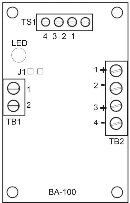
The EVB-BA-100 provides a means to switch in a backup amplifier in the event of a primary amp failure. One backup amp can be provided in reserve for several primary amps. Amplifier outputs are connected at TB2, and speaker field wiring at TB1. Supervisory and 24 VDC power inputs are provided at TS1. The LED on-board activates when the backup amp has been switched in. All wiring is power-limited. Mounts to snaptrack or insulating nylon standoffs.
The EVB-BA-100 is compatible with both 25VRMS and 70VRMS audio signals.
INSTALLATION:
Mounting: The EVB-BA-100 is mounted in the same cabinet that houses the primary amplifier. It is designed to be mounted into standard 3" snap track material. The board also has mounting holes at the corners for stand-off mounts where necessary.
Fig. 1 - Board
TB1:
Ter. 1 - Ckt. Neg
Ter. 2 - +24 VDC
Ter. 3 - Gen Input
Ter. 4 - +24 VDC
TB1:
Ter. 1 & 2 - Audio Output
TB2:
Ter. 1&2 - 25/70 VRMS Audio Input from backup amplifier
Ter. 3&4 - 25/70 VRMS Audio Input from primary amplifier
JUMPERS:
J1: jumps TS1-2 to TS1-4
LED 1:
ON: backup audio switched in
SPECIFICATIONS:
Power: 24 VDC
Current: 40 mA Standby 10 mA Active
Fig. 2 - Typical Connection Detail

Field wiring connections:
6-32 wire clamp screw 14-18 AWG
8-32 wire clamp screw 12-18 AWG
Horizontal wire entry terminal 18-26 AWG
Wire gauge determined by circuit load



Marke : BOSCH
Modell : EVB-BA100
Kategorie : Detektor