
SLZ-KF25VAD - Klimaanlage MITSUBISHI - Kostenlose Bedienungsanleitung
Finden Sie kostenlos die Bedienungsanleitung des Geräts SLZ-KF25VAD MITSUBISHI als PDF.


| Produkttyp | Deckenkassette-Klimaanlage (Innengerät) |
| Modell | SLZ-KF25VAD |
| Hersteller | Mitsubishi Electric |
| Kältemittel | R410A |
| Kühlbetrieb | Ja |
| Heizbetrieb | Ja |
| Fernbedienung | Kabelgebunden (PAR-33MAA) und kabellos (optional) |
| Anzahl Luftauslässe | 4 |
| Luftfilter | Waschbar, leicht zugänglich |
| Kondensatpumpe | Integriert |
| Stromversorgung | 230 V AC, 50/60 Hz |
| Mindestinstallationshöhe | 2,5 m über Boden |
| Abmessungen (Deckenöffnung) | 576 x 576 mm bis 610 x 610 mm |
| Kompatibilität | Außengeräte von Mitsubishi Electric (Baureihe SLZ-KF) |
| Steuerungsmöglichkeiten | Kabelfernbedienung, optional Infrarot-Fernbedienung |
| Zubehör im Lieferumfang | Montageschablone, Dichtungen, Rohrabdeckungen, Kondensatanschluss |
| Wartungsfunktion | Easy Maintenance (Smooth Maintenance) zur Datenabfrage |
| Lamellensteuerung | Automatisch und manuell, je 4 Auslässe einzeln einstellbar |
| Sicherheitshinweise | Elektrische Erdung erforderlich, Schutzschalter empfohlen |
| Installationsart | Deckenmontage, nur durch Fachpersonal |
Häufig gestellte Fragen - SLZ-KF25VAD MITSUBISHI
Benutzerfragen zu SLZ-KF25VAD MITSUBISHI
0 Frage zu diesem Gerät. Beantworten Sie die, die Sie kennen, oder stellen Sie Ihre eigene.
Eine neue Frage zu diesem Gerät stellen
Laden Sie die Anleitung für Ihr Klimaanlage kostenlos im PDF-Format! Finden Sie Ihr Handbuch SLZ-KF25VAD - MITSUBISHI und nehmen Sie Ihr elektronisches Gerät wieder in die Hand. Auf dieser Seite sind alle Dokumente veröffentlicht, die für die Verwendung Ihres Geräts notwendig sind. SLZ-KF25VAD von der Marke MITSUBISHI.
BEDIENUNGSANLEITUNG SLZ-KF25VAD MITSUBISHI
Air Conditioners
SLZ-KF25, KF35, KF50, KF60VA3
Contents
- Safety precautions 2
- Selecting the installation location.... 2
- Installation diagram.... 3
- Installing the indoor unit 3
- Refrigerant piping work 5
-
Drainage piping work 7
-
Electrical work....8
- Test run 15
- System control 17
- Installing the grille 17
- Easy maintenance function 20
Note:
The phrase “Wired remote controller” in this installation manual refers only to the PAR-33MAA. If you need any information for the other remote controller, please refer to either the installation manual or initial setting manual which are included in these boxes.
1. Safety precautions
- Be sure to read "Safety precautions" before installing the air conditioner.
- Be sure to observe the cautions specified here as they include important items related to safety.
• The indications and meanings are as follows.
Warning:
Could lead to death, serious injury, etc.
Caution:
Could lead to serious injury in particular environments when operated incorrectly.
- After reading this manual, be sure to keep it together with the instruction manual in a handy place on the customer's site.
: Indicates a part which must be grounded.
Warning:
Carefully read the labels affixed to the main unit.
Install the indoor unit at least 2.5 m above floor or grade level.
For appliances not accessible to the general public.
Warning:
• Do not install it by yourself (customer).
Incomplete installation could cause injury due to fire, electric shock, the unit falling or leakage of water. Consult the dealer from whom you purchased the unit or special installer.
- Install the unit securely in a place which can bear the weight of the unit. When installed in an insufficient strong place, the unit could be injured.
- Use the specified wires to connect the indoor and outdoor units securely and attach the wires firmly to the terminal board connecting sections so the stress of the wires is not applied to the sections.
Incomplete connecting and fixing could cause fire.
- Do not use intermediate connection of the power cord or the extension cord and do not connect many devices to one AC outlet. It could cause a fire or an electric shock due to defective contact, defective insulation, exceeding the permissible current, etc.
- Check that the refrigerant gas does not leak after installation has completed.
- Perform the installation securely referring to the installation manual. Incomplete installation could cause a personal injury due to shock, the unit falling or leakage of water.
- Perform electrical work according to the installation manual and be sure to use an exclusive circuit. If the capacity of the power circuit is insufficient or there is incomplete electrical work, it could result in a fire or an electric shock.
- The user should never attempt to repair the unit or transfer it to another location.
- The appliance shall be installed in accordance with national wiring regulations.
- If the supply cord is damaged, it must be replaced by the manufacturer, its service agent or similarly qualified persons in order to avoid a hazard.
- Attach the electrical part cover to the indoor unit and the service panel to the indoor unit.
If the electrical part cover in the indoor unit and/or the service panel in the outdoor unit are not attached securely, it could result in a fire or an electric shock due to dust, water, etc. - Be sure to use the part provided or specified parts for the installation work. The use of defective parts could cause an injury or leakage of water due to a fire, an electric shock, the unit falling, etc.
- Ventilate the room if refrigerant leaks during operation.
If the refrigerant comes in contact with a flame, poisonous gases released. - When installing or relocating, or servicing the air conditioner, use only the specified refrigerant (R410A) to charge the refrigerant lines. Do not mix it with air refrigerator and do not allow air to remain in the lines.
If air is mixed with the refrigerant, then it can be the cause of abnormal high pressure in the refrigerant line, and may result in an explosion and hazards.
The use of any refrigerant other than that specified for the system will cause mechanical failure or system malfunction or unit breakdown. In the case, this could lead to a serious impediment to securing product safety.
Caution:
• Perform grounding.
Do not connect the ground wire to a gas pipe, water pipe arrester or telephone ground wire. Defective grounding could cause an electric shock.
- Do not install the unit in a place where an inflammable gas leaks.
If gas leaks and accumulates in the area surrounding the unit, it could cause an explosion.
- Install a ground leakage breaker depending on the installation place (where it is humid).
If a ground leakage breaker is not installed, it could cause shock.
- Perform the drainage/piping work securely according to the instal manual.
If there is a defect in the drainage/piping work, water could drop from the unit and household goods could be wet and damaged. - Fasten a flare nut with a torque wrench as specified in this manual.
When fastened too tight, a flare nut may broken after a long period and cause a leakage of refrigerant. - If the unit is run for long hours when the air above the ceiling is at high temperature/high humidity (dew point above 26 °C), dew condensation may be produced in the indoor unit or the ceiling materials. When operating the units in this condition, add insulation material (10-20 mm) to the entire surface of the unit and ceiling materials to avoid dew condensation.
2. Selecting the installation location
2.1. Indoor unit
• Where airflow is not blocked.
- Where cool air spreads over the entire room.
• Where it is not exposed to direct sunshine.
- At a distance 1 m or more away from your TV and radio (to prevent picture from being distorted or noise from being generated).
- Where airflow is not blocked. - Where cool air spreads over the entire room. - Where it is not exposed to direct sunshine. - At a distance 1m or more away from your TV and radio (to prevent picture from being distorted or noise from being generated).
- In a place as far away as possible from fluorescent and incandescent lights (so the infrared remote control can operate the air conditioner normally).
- Where the air filter can be removed and replaced easily.
- In a place as far away as possible from fluorescent and incandescent lights (so the infrared remote control can operate the air conditioner normally). - Where the air filter can be removed and replaced easily.
Warning:
Mount the indoor unit into a ceiling strong enough to withstand the weight of the unit.
2.2. Wireless remote controller mounting (For SLP-2FAL\*)
- Place of mounting
• Where it is easy to operate and easily visible.
• Where children can not touch.
- Mounting
Select a position about 1.2m above the floor, check that signals from the remote controller are surely received by the indoor unit from that position ('beep' or 'beep-beep' receiving tone sounds). After that, attach remote controller holder to a pillar or wall and set the wireless remote controller.
In rooms where inverter type fluorescent lamps are used, the signal from the wireless remote controller may not be received.
3. Installation diagram
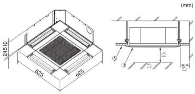
Fig. 3-1
3.1. Indoor unit (Fig. 3-1)
④ Ceiling
® Grille
Obstacle
© Min. 1000 mm
⑤ Min. 500 mm (Entire periphery)
If setting the maintenance space for ⑤, be sure to leave is a minimum of 700 mm.

Warning:
Mount the indoor unit on a ceiling strong enough to withstand the weight of the unit.
3.2. Outdoor unit
Refer to the outdoor unit installation manual.
4. Installing the indoor unit
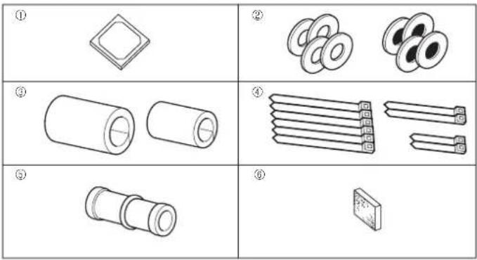
Fig. 4-1
4.1. Check the indoor unit accessories (Fig. 4-1)
The indoor unit should be supplied with the following accessories.
| Accessory name Q'ty | ||
| 1 | Installation template 1 | |
| 2 | Washers (with insulation) | 4 |
| Washers (without insulation) | 4 | |
| 3 | Pipe cover (for refrigerant piping joint) | |
| small diameter (liquid) | 1 | |
| large diameter (gas) | 1 | |
| 4 | Band (large) | 6 |
| Band (middle) | 2 | |
| Band (small) | 2 | |
| 5 | Drain socket 1 | |
| 6 | Insulation | 1 |
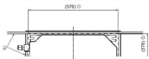
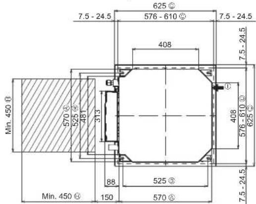
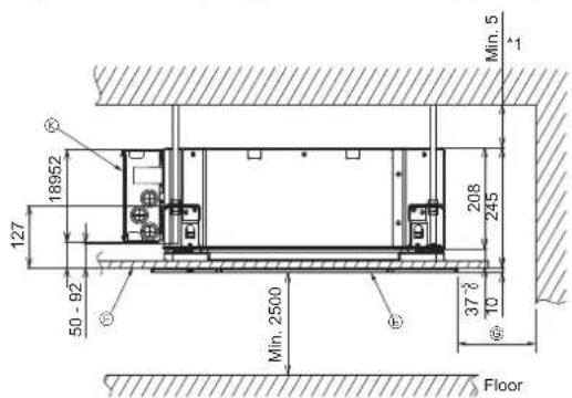
Fig. 4-2
4.2. Ceiling openings and suspension bolt installation locations (Fig. 4-2)

Caution:
Install the indoor unit at least 2.5 m above floor or grade level.
For appliances not accessible to the general public.
- Using the installation template and the gauge (supplied as an accessory with the grille), make an opening in the ceiling so that the main unit can be installed as shown in the diagram. (The method for using the template and the gauge are shown.)
* Before using, check the dimensions of template and gauge, because they change due to fluctuations of temperature and humidity.
* The dimensions of ceiling opening can be regulated within the range shown in following diagram; so center the main unit against the opening of ceiling, ensuring that the respective opposite sides on all sides of the clearance between them becomes identical.
• Use M10 (3/8") suspension bolts.
* Suspension bolts are to be procured at the field.
• Install securely, ensuring that there is no clearance between the ceiling panel & grille, and between the main unit & grille.
④ Outer side of main unit
© Bolt pitch
© Ceiling opening
⑪ Outer side of Grille
© Grille
© Ceiling
© Min. 500 mm (Entire periphery)
If setting the maintenance space for Ⓗ, be sure to leave is a minimum of 700 mm.
⑧ Maintenance space
① Fresh air intake
Angle
Electric component box
* Leave the maintenance space at the electric component box end.
*1 When installing in an existing ceiling unit location or applying additional heat insulation, ensure a minimum space of 25 mm.
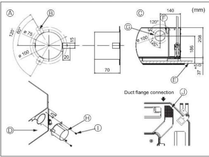
Fig. 4-3
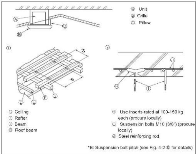
Fig. 4-4
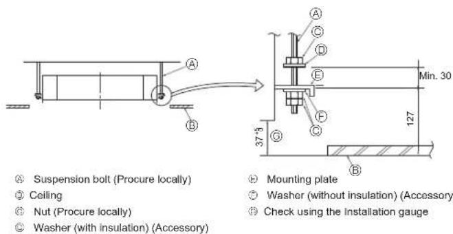
Fig. 4-5
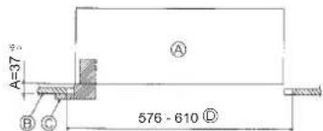
Fig. 4-6
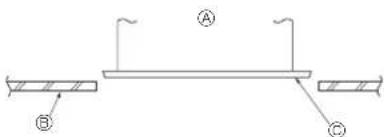
Fig. 4-7
4.3. Installation of duct (in case of fresh air intake) (Fig. 4-3)
Caution:
Linkage of duct fan and air conditioner
In case that a duct fan is used, be sure to make it linked with the air conditioner when outside air is taken.
Do not run the duct fan only. It can cause dew drop.
Making a duct flange (prepared locally)
• The shape of duct flange shown left is recommended.
Installation of duct flange
• Cut out the cutout hole. Do not knock it out.
- Install a duct flange to the cutout hole of the indoor unit with three 4 × 10 lapping screws which should be prepared locally.
Installation of duct (should be prepared locally)
• Prepare a duct of which inner diameter fits into the outer diameter of the duct flange.
- In case that the environment above the ceiling is high temperature and high humidity, wrap the duct in a heat insulate to avoid causing dew drop on the wall.
Remove the drain pan insulation.
④ Duct flange recommended shape
(Thickness:0.8 or more)
⑥ 3-ø5 hole
① Detail drawing of fresh air intake
© Indoor unit
⑤ Ceiling surface
⑤ 3-Tapping screw hole
© 073.4 cutout hole
① Duct flange (Prepared locally)
① 4 × 10 Tapping screw (Prepared locally)
② Insulation
4.4. Suspension structure (Give site of suspens strong structure) (Fig. 4-4)
- The ceiling work differs according to the construction of the building. Building constructors and interior decorators should be consulted for details.
(1) Extent of ceiling removal: The ceiling must be kept completely horizontal and the ceiling foundation (framework: wooden slats and slat holders) must be reinforced in order to protect the ceiling from vibration.
(2) Cut and remove the ceiling foundation.
(3) Reinforce the ends of the ceiling foundation where it has been cut and add ceiling foundation for securing the ends of the ceiling board.
(4) When installing the unit on a slanting ceiling, interlock a pillow between the ceiling and the grille and set so that the unit is installed horizontally.
① Wooden structures
- Use tie beams (single-story houses) or second floor beams (two story houses) as reinforcing members.
- Wooden beams for suspending air conditioners must be sturdy and their sides must be at least 6 cm long if the beams are separated by not more than 90 cm and their sides must be at least 9 cm long if the beams are separated by as much as 180 cm. The size of the suspension bolts should be ø10 (3/8"). (The bolts do not come with the unit.)
② Ferroconcrete structures
Secure the suspension bolts using the method shown, or use steel or wooden hangers, etc. to install the suspension bolts.
4.5. Unit suspension procedures (Fig. 4-5)
Suspend the main unit as shown in the diagram.
- In advance, set the parts onto the suspension bolts in the order of the washers (with insulation), washers (without insulation) and nuts (double).
• Fit the washer with cushion so that the insulation faces downward. -
In case of using upper washers to suspend the main unit, the lower washers (with insulation) and nuts (double) are to be set later.
-
Lift the unit to the proper height of the suspension bolts to insert the mounting plate between washers and then fasten it securely.
-
When the main unit can not be aligned against the mounting hole on the ceiling, it is adjustable owing to a slot provided on the mounting plate. (Fig. 4-6)
- Make sure that step A is performed within 37-42 mm. Damage could result by failing to adhere to this range.
4.6. Confirming the position of main unit and tightening the suspension bolts (Fig. 4-7)
- Using the gauge attached to the grille, ensure that the bottom of the main unit is properly aligned with the opening of the ceiling. Be sure to confirm this, otherwise condensation may form and drip due to air leakage etc.
- Confirm that the main unit is horizontally levelled, using a level or a vinyl tube filled with water.
- After checking the position of the main unit, tighten the nuts of the suspension bolts securely to fasten the main unit.
- The installation template can be used as a protective sheet to prevent dust from entering the main unit when the grilles are left unattached for a while or when the ceiling materials are to be lined after installation of the unit is finished.
* As for the details of fitting, refer to the instructions given on the Installation template.
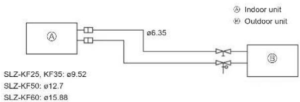
Fig. 5-1
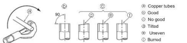
Fig. 5-2
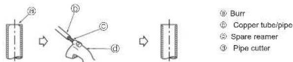
Fig. 5-3
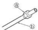
Fig. 5-4
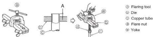
Fig. 5-5
5.1. Precautions
For devices that use R410A refrigerant
- Use alkylbenzene oil (small amount) as the refrigeration oil applied to the flared sections.
- Use C1220 copper phosphorus for copper and copper alloy seamless pipes, to connect the refrigerant pipes. Use refrigerant pipes with the thicknesses specified in the table below. Make sure the insides of the pipes are clean and do not contain any harmful contaminants such as sulfuric compounds, oxidants, debris, or dust.
Warning:
When installing or relocating, or servicing the air conditioner, use only the specified refrigerant written on outdoor unit to charge the refrigerant lines. Do not mix it with any other refrigerant and do not allow air to remain in the lines.
If air is mixed with the refrigerant, then it can be the cause of abnormal high pressure in the refrigerant line, and may result in an explosion and other hazards.
The use of any refrigerant other than that specified for the system will cause mechanical failure or system malfunction or unit breakdown. In the worst case, this could lead to a serious impediment to securing product safety.
5.2. Refrigerant pipe (Fig. 5-1)
Piping preparation
• Refrigerant pipes of 3, 5, 7, 10 and 15 m are available as optional items.
(1) Table below shows the specifications of pipes commercially available.
| Model Pipe | Outside diameter | Min. wall thickness | Insulation thickness | Insulation material | ||
| mm inch | ||||||
| SLZ-KF25 SLZ-KF35 | For liquid | 6.35 1/4 | 0.8 mm | 8 mm | Heat resist-ing foam plastic 0.045 specific gravity | |
| For gas | 9.52 3/8 | 0.8 mm | 8 mm | |||
| SLZ-KF50 | For liquid | 6.35 1/4 | 0.8 mm | 8 mm | ||
| For gas | 12.7 1/2 | 0.8 mm | 8 mm | |||
| SLZ-KF60 | For liquid | 6.35 1/4 | 0.8 mm | 8 mm | ||
| For gas | 15.88 | 5/8 | 0.8 mm | 8 mm | ||
(2) Ensure that the 2 refrigerant pipes are well insulated to prevent condensation. (3) Refrigerant pipe bending radius must be 100 mm or more.
Caution:
Using careful Insulation of specified thickness. Excessive thickness prevents storage behind the indoor unit and smaller thickness causes dew drippage.
5.3. Flaring work
• Main cause of gas leakage is defect in flaring work.
Carry out correct flaring work in the following procedure.
5.3.1. Pipe cutting (Fig. 5-2)
• Using a pipe cutter cut the copper tube correctly.
5.3.2. Burrs removal (Fig. 5-3)
• Completely remove all burrs from the cut cross section of pipe/tube.
- Put the end of the copper tube/pipe to downward direction as you remove burrs in order to avoid burrs drop in the tubing.
5.3.3. Putting nut on (Fig. 5-4)
- Remove flare nuts attached to indoor and outdoor unit, then put them on pipe/tube having completed burr removal.
(not possible to put them on after flaring work)
5.3.4. Flaring work (Fig. 5-5)
- Carry out flaring work using flaring tool as shown at the right.
| Pipe diameter (mm) | Dimension | |
| A (mm) | B _-0.4^+0 (mm) | |
| When the tool for R410A is used | ||
| Clutch type | ||
| 6.35 0 - 0.5 | 9.1 | |
| 9.52 0 - 0.5 | 13.2 | |
| 12.7 0 - 0.5 | 16.6 | |
| 15.88 0 - 0.5 | 19.7 | |
Firmly hold copper tube in a die in the dimension shown in the table at above.
5. Refrigerant piping work
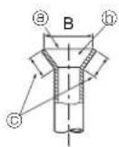
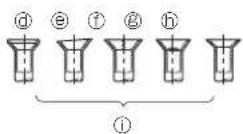
Fig. 5-6
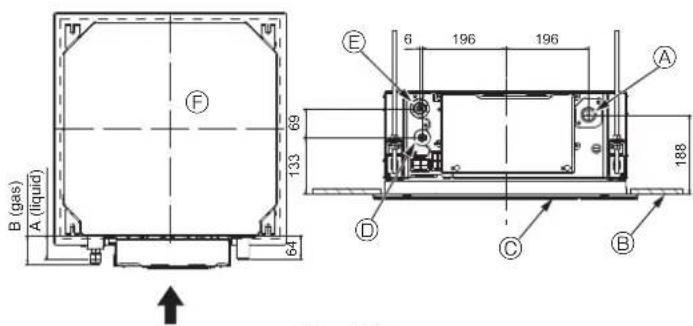
Fig. 5-7
natural_image
Technical line drawing of a mechanical assembly with no visible text or symbols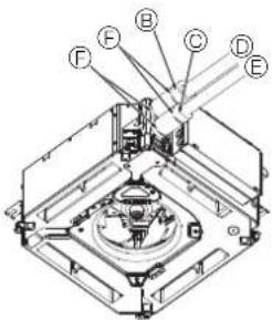
② Refrigerant pipe and insulating material (Procure locally)
⑤ Pipe cover (large) (Accessory)
© Pipe cover (small) (Accessory)
① Refrigerant pipe (gas)
⑤ Refrigerant pipe (liquid)
© Band (Accessory)
© Cross-sectional view of connection
⑧ Refrigerant pipe
① Insulating material
① Squeeze
Fig. 5-8
natural_image
Illustration of a hand using a tool to lift a cylindrical object, no text or symbols presentFig. 5-9
5.3.5. Check (Fig. 5-6)
• Compare the flared work with a figure in right side hand.
- If flare is noted to be defective, cut off the flared section and do flaring work again.
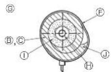
© Smooth all around
① Scratch on flared plane
⑤ Inside is shining without any scratches
Cracked
© Even length all around
Uneven
⑨ Too much
① Bad examples
© Tilted
5.4. Refrigerant and drainage piping locations (Fig. 5-7)
④ Drain pipe
© Ceiling
© Grille
Refrigerant pipe (liquid)
© Refrigerant pipe (gas)
⊕ Main unit
| Model | Dimension | |
| A (liquid) B (gas) | ||
| SLZ-KF25 | 63 mm | 72 mm |
| SLZ-KF35 | ||
| SLZ-KF50 | 63 mm | 78 mm |
| SLZ-KF60 | ||
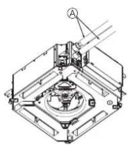
5.5. Pipe connection (Fig. 5-8)
Indoor unit
1) When using commercially available copper pipes:
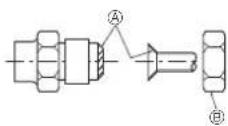
- Apply thin layer of refrigerant oil to pipe and joint seating surface before tightening flare nut.
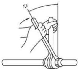
• Use two wrenches to tighten piping connections. - Air-purge the refrigerant piping using your own refrigerant gas (don't air-purge the refrigerant charged in the outdoor unit).
- Use leak detector or soapy water to check for gas leaks after connections are completed.
• Use flared nut installed to this indoor unit. - In case of reconnecting the refrigerant pipes after detaching, make the flared part of pipe re-fabricated.
- Use refrigerant piping insulation provided to insulate indoor unit connections. Insulate carefully following shown below.
2) Heat insulation for refrigerant pipes:
① Wrap the enclosed large-sized pipe cover around the gas pipe, making sure that the end of the pipe cover touches the side of the unit.
② Wrap the enclosed small-sized pipe cover around the liquid pipe, making sure that the end of the pipe cover touches the side of the unit.
③ Secure both ends of each pipe cover with the enclosed bands. (Attach the bands 20 mm from the ends of the pipe cover.)
Make sure that the slit in the pipe cover is facing upward when it is installed.
See that stop valve on outdoor unit is fully shut (unit is shipped with valve shut). After all piping connections between indoor and outdoor unit have been completed, vacuum-purge air from system through the service port for the stop valve on the outdoor unit. After completing procedures above, open outdoor unit stop valves stem fully. This completes connection of refrigerant circuit between indoor and outdoor units. Stop valve instructions are marked on outdoor unit.
Flare nut tightening
- Apply a thin coat of refrigeration oil on the seat surface of pipe.
- For connection first align the center, then tighten the first 3 to 4 turns of flare nut.
- Use tightening torque table below as a guideline for indoor unit side union joint section, and tighten using two wrenches. Excessive tightening damages the flare section.
Ⓐ Apply refrigerating machine oil over the entire flare seat surface.
⑧ Use correct flare nuts meeting the pipe size of the outdoor unit.
© Flare nut tightening torque
| Copper pipe O.D. (mm) | Flare nut O.D. (mm) | Tightening torque (N·m) |
| ø6.35 17 14 - 18 | ||
| ø9.52 22 34 - 42 | ||
| ø12.7 26 49 - 61 | ||
| ø15.88 29 68 - 82 |
6. Drainage piping work
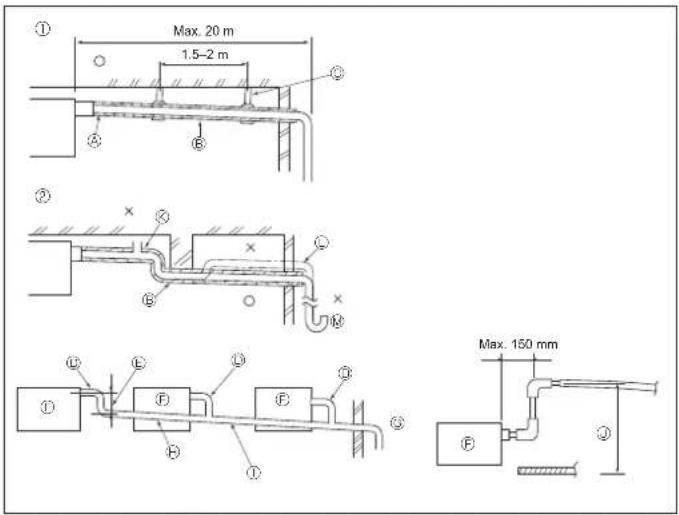
Fig. 6-1
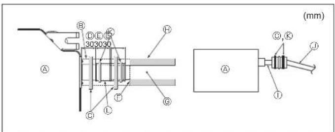
Fig. 6-2
6.1. Drainage piping work (Fig. 6-1)
- Use VP25 (O. D. 32 PVC TUBE) for drain piping and provide 1/100 or m downward slope.
- Be sure to connect the piping joints using a polyvinyl type adhesive.
- Observe the figure for piping work.
- Use the included drain hose to change the extraction direction.
① Correct piping
© Support metal
② Wrong piping ⑨ Air bleeder
④ Insulation (9 mm or more) ① Raised
⑤ Downward slope (1/100 or more) ⑥ Odor trap
Grouped piping
O. D. ∅32 PVC TUBE
⑤ Make it as large as possible
② Indoor unit
⑤ Make the piping size large for grouped piping
⑧ Downward slope (1/100 or more)
① O. D. ø38 PVC TUBE for grouped piping (9 mm or more insulation)
① Up to 850 mm
-
Connect the drain socket (supplied with the unit) to the drain port. (Fig. 6-2) (Affix the tube using PVC adhesive then secure it with a band.)
-
Install a locally purchased drain pipe (PVC pipe, O.D. 032).
(Affix the pipe using PVC adhesive then secure it with a band.) - Insulate the tube and pipe. (PVC pipe, O.D. ø32 and socket)
- Check that drain flows smoothly.
- Insulate the drain port with insulating material, then secure the material with a band. (Both insulating material and band are supplied with the unit.)
⑧ Main unit ⑨ Drain pipe (O.D. ∅32 PVC TUBE)
⑤ Insulating material ⑥ Insulating material (purchased locally)
© Band (large) ① Transparent PVC pipe
Drain port (transparent) O.D. ø32 PVC TUBE (Slope 1/100 or more)
⑤ Insertion margin ⑥ Band (middle)
Matching Drain socket
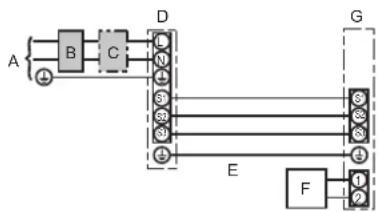
7.1. Indoor unit power supplied from outdoor unit
The following connection patterns are available.
The outdoor unit power supply patterns vary on models.
1:1 System
flowchart
graph TD
    A["A"] --> B["B"]
    B --> C["C"]
    C --> D["D"]
    D --> E["E"]
    E --> F["F"]
    F --> G["G"]
    style A fill:#f9f,stroke:#333
    style B fill:#ccf,stroke:#333
    style C fill:#ccf,stroke:#333
    style D fill:#cfc,stroke:#333
    style E fill:#fcc,stroke:#333
    style F fill:#cff,stroke:#333
    style G fill:#ffc,stroke:#333
A Outdoor unit power supply
B Earth leakage breaker
C Wiring circuit breaker or isolating switch
D Outdoor unit
E Indoor unit/outdoor unit connecting cables
F Remote controller
G Indoor unit
| Indoor unit model SLZ | ||
| Wiring Wire No. × size (mm2) | Indoor unit-Outdoor unit *1 3 × 1.5 (polar) | |
| Indoor unit-Outdoor unit earth *1 1 × Min. 1.5 | ||
| Indoor unit earth 1 × Min. 1.5 | ||
| Remote controller-Indoor unit *2 2 × 0.3 (Non-polar) | ||
| Circuit rating | Indoor unit (Heater) L-N *3 — | |
| Indoor unit-Outdoor unit S1-S2 *3 230 VAC | ||
| Indoor unit-Outdoor unit S2-S3 *3 24 VDC | ||
| Remote controller-Indoor unit *3 12 VDC | ||
*1.
Max. 45 m
If 2.5 mm ^2 used, Max. 50 m
If 2.5 mm² used and S3 separated, Max. 80 m
*2. Max. 500 m
(When using 2 remote controllers, the maximum wiring length for the remote controller cables is 200 m.)
^3 . The figures are NOT always against the ground.
S3 terminal has 24 VDC against S2 terminal. However between S3 and S1, these terminals are not electrically insulated by the transformer or other device.
Notes: 1. Wiring size must comply with the applicable local and national code.
-
Power supply cords and indoor unit/outdoor unit connecting cords shall not be lighter than polychloroprene sheathed flexible cord. (Design 60245 IEC 57)
-
Install an earth longer than other cables.
-
Indoor and outdoor connecting wires have polarities. Make sure to match the terminal number (S1, S2, S3) for correct wirings.
-
Wiring for remote controller cable shall be apart (5 cm or more) from power source wiring so that it is not influenced by electric noise from power source wiring.
Warning:
Never splice the power cable or the indoor-outdoor connection cable, otherwise it may result in a smoke, a fire or communication failure.
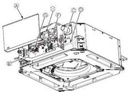
Electric component cover
© Indoor/Outdoor unit connecting terminal
⑥ Electric component box
© Wired remote controller terminal
② Entry for Indoor-Outdoor connecting cable
Indoor controller
Entry for wired remote controller cable
① Earth cable
Cable clamp
Cable strap
Fig. 7-1
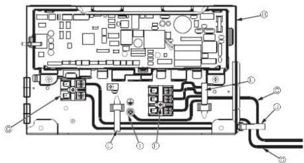
Fig. 7-2
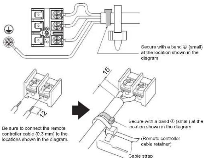
Fig. 7-3
7.2. Indoor unit (Fig. 7-1) (Fig. 7-2) (Fig. 7-3)
Work procedure
- Loosen the two screws securing the electric component cover, and then slide and remove the cover.
- Route the wires along the wiring routes and through the wire inlets in the electric component box. (Procure the power supply cord and indoor/outdoor unit connecting cable locally.)
- Securely connect the power supply cord and the indoor/outdoor unit connecting cable to the terminal block.
- Secure the wires with the cable straps inside the electric component box. Secure the wires with cable straps as cushioning components so that no stress is applied to the connecting sections of the terminal block when tension is generated.
- Install the electric component cover.
Make sure that the wires do not get pinched. - Secure the wires with the cable straps outside the electric component box.

Warning:
- Insert hook the electric component cover into the bent support on the electric component box and attach the cover securely. If it is attached incorrectly, it could result in a fire, electric shock due to dust, water, etc.
- Use the specified indoor/outdoor unit connecting cable to connect the indoor and outdoor units and fix the cable to the terminal block securely so that no stress is applied to the connecting section of the terminal block. Incomplete connection or fixing of the cable could result in a fire.
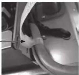
- Secure all of the indoor/outdoor unit connecting cables with the cable strap on the side of the electric component box.
natural_image
Close-up of a car wheel assembly with a hand adjusting the component (no visible text or symbols)
Caution:
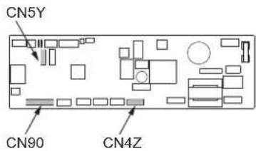
• Before installing the grille, make sure that the junction wire is connected.
- If the grille has signal receiver or i-See sensor, the pack of grille includes junction wire.
Signal receiver: CN90
3D i-See sensor: CN5Y
3D I-See sensor motor: CN4Z
7. Electrical work
natural_image
Mechanical component diagram labeled A and D, showing internal parts without any readable text or symbols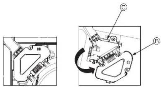
Fig. 7-5
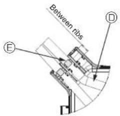
Fig. 7-6
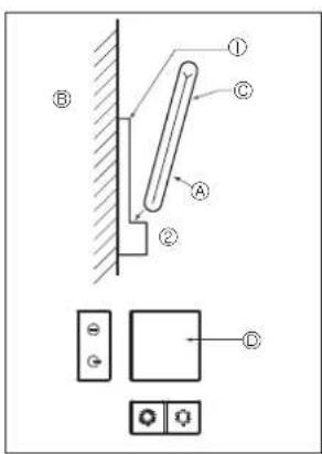
Fig. 7-7
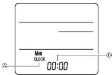
Fig. 7-8
7.2.1. Installing the i-See sensor and signal receiver
Before installing the grille, connect the junction wires included with the grille accessories and place them in the connector box.
① Remove the two screws securing the wire cover of the main unit, and then open the cover.
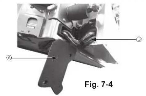
② Route the wires of the i-See sensor and signal receiver through the wire inlets in the electric component box as shown in the diagram and around the bushings on the side of the main unit. (Fig. 7-4)
When routing the wires, open the clamp securing the grille junction wire, and then secure the grille junction wire and the wires of the i-See sensor and signal receiver with the clamp.
③ Remove the one screw securing the connector box cover, and then open the cover. (Fig. 7-5)
④ Place the junction wire connector in the connector box.
⑤ Install the wire cover and connector box cover.
Caution:
When installing the covers, make sure that the wires do not get pinched.
Fit the band securing the junction wires between the ribs on the connector box as shown in the diagram. (Fig. 7-6)
④ Wire cover
⑧ Connector box cover
© Connector box
⑩ i-See sensor or signal receiver lead wire (Grille accessory)
© Band
7.3. Remote controller
7.3.1. Wired remote controller
1) Installing procedures
Refer to the installation manual that comes with each remote controller for details.
2) Function selection of remote controller
If two remote controllers are connected, set one to "Main" and the other to "Sub".
For setting procedures, refer to "Function selection of remote controller" in the operation manual for the indoor unit.
7.3.2. For wireless remote controller
1) Installation area
• Area in which the remote controller is not exposed to direct sunshine.
• Area in which there is no nearby heating source.
- Area in which the remote controller is not exposed to cold (or hot) winds.
• Area in which the remote controller can be operated easily.
• Area in which the remote controller is beyond the reach of children.
2) Installation method (Fig. 7-7)
① Attach the remote controller holder to the desired location using 2 tapping screws.
② Place the lower end of the controller into the holder.
Ⓐ Remote controller Ⓑ Wall Ⓞ Display panel Ⓓ Receiver
- The signal can travel up to approximately 7 meters (in a straight line) within 45 degrees to both right and left of the center line of the receiver.
3) Setting (Clock setting) (Fig. 7-8)
① Insert batteries or press the ● CLOCK button with something sharp.
[CLOCK] Ⓐ and [:] Ⓢ blinks.
② Press the RESET ● button with something sharp.
③ Press the button to set the time.
Press the DAY button to set the Day.
④ Press the ● CLOCK button with something sharp at the end.
[CLOCK] and [:] lighted.
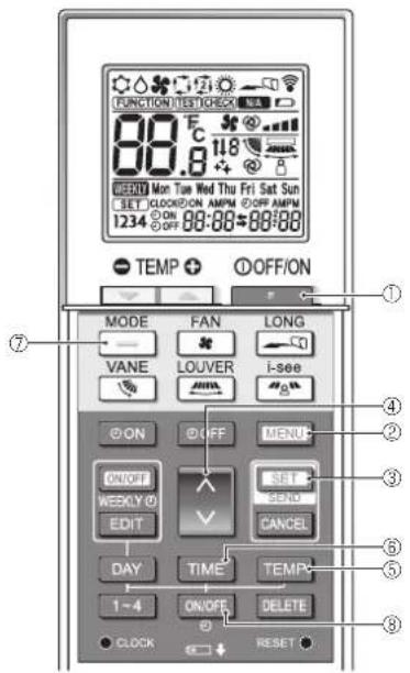
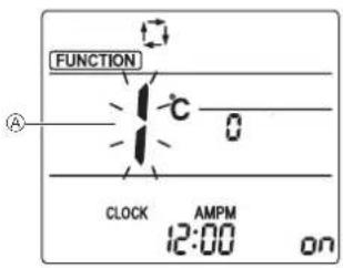
Fig. 7-9
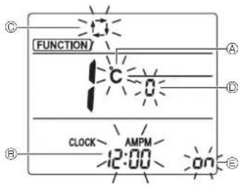
Fig. 7-10
4) Initial setting
The following settings can be made in the initial setting mode.
| Item | Setting | Fig. 7-10 |
| Temperature unit | °C/°F | |
| Time display | 12-hour format/24-hour format | |
| AUTO mode | Single set point/Dual set point | |
| Pair No. | 0-3 | |
| Backlight | On/Off |
4-1. Switching to the initial setting mode
- Press the button ① to stop the air conditioner.
- Press the MENU button ②.
The Function setting screen will be displayed and the function No. Ⓠ will blink. (Fig. 7-9)
Press the button ④ to change the function No.
- Check that function No. "1" is displayed, and then press the SET button ③. The display setting screen will be displayed. (Fig. 7-10)
4-2. Changing the temperature unit Ⓜ
Press the TEMP button ⑤.
Each time the TEMP button ⑤ is pressed, the setting switches between Cand 'F.
C: The temperature is displayed in degrees Celsius.
F: The temperature is displayed in degrees Fahrenheit.
4-3. Changing the time display Ⓔ
Press the TIME button ⑥.
Each time the TIME button ⑥ is pressed, the setting switches between 12:00 and 24:00
AMTS
12:00: The time is displayed in the 12-hour format.
24:00: The time is displayed in the 24-hour format.
4-4. Changing the AUTO mode ©
Press the — button Ⓐ.
Each time the — button ⑦ is pressed, the setting switches between and
☐: The AUTO mode operates as the usual automatic mode.
12: The AUTO mode operates using dual set points.
4-5. Changing the pair No. ⑪
Press the button ④.
Each time the button ④ is pressed, the pair No. 0–3 changes.
| Pair No. of wireless remote controller Indoor PC board | |
| 0 Initial setting | |
| 1 Cut J41 | |
| 2 Cut J42 | |
| 3 Cut J41, J42 | |
4-6. Changing the backlight setting Ⓔ
Press the ON/OFF button ⓗ.
Each time the ON/OFF button Ⓞ is pressed, the setting switches between on and o FF.
on: The backlight comes on when a button is pressed.
oFF: The backlight does not come on when a button is pressed.
7. Electrical work
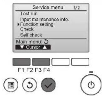
Fig. 7-11
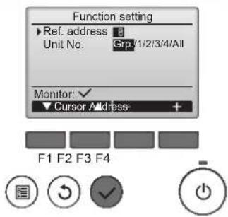
Fig. 7-12
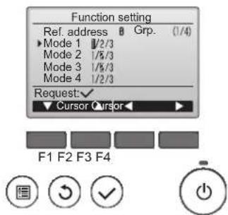
Fig. 7-13
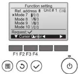
Fig. 7-14
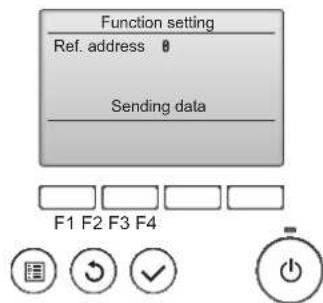
Fig. 7-15
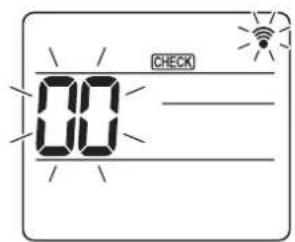
Fig. 7-16
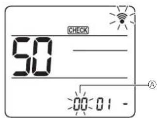
Fig. 7-17
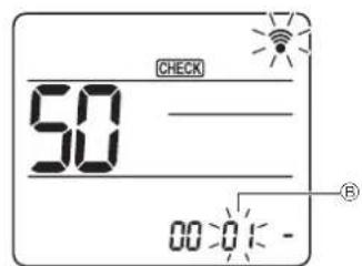
Fig. 7-18
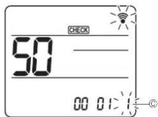
Fig. 7-19
7.4. Function settings
7.4.1. By wired remote controller
① (Fig. 7-11)
- Select "Service" from the Main menu, and press the [SELECT] button.
- Select "Function setting" with the [F1] or [F2] button, and press the [SELECT] button.
② (Fig. 7-12)
- Set the indoor unit refrigerant addresses and unit numbers with the [F1] through [F4] buttons, and then press the [SELECT] button to confirm the current setting.
When the [SELECT] button is pressed, the target indoor unit will start fan operation. If the unit is common or when running all units, all indoor units for the selected refrigerant address will start fan operation.
③ (Fig. 7-13)
- When data collection from the indoor units is completed, the current settings appears highlighted. Non-highlighted items indicate that no function settings are made. Screen appearance varies depending on the "Unit No." setting.
④ (Fig. 7-14)
- Use the [F1] or [F2] button to move the cursor to select the mode number, and change the setting number with the [F3] or [F4] button.
⑤ (Fig. 7-15)
- When the settings are completed, press the [SELECT] button to send the setting data from the remote controller to the indoor units.
- When the transmission is successfully completed, the screen will return to the Function setting screen.
7.4.2. By wireless remote controller (Fig. 7-16, Fig. 7-17, Fig. 7-18, Fig. 7-19)
① Going to the function select mode
Press the MENU button between of 5 seconds.
(Start this operation from the status of remote controller display turned off.) [CHECK] is lighted and "00" blinks. (Fig. 7-16)
Press the Ⓞ button to set the "50"
Direct the wireless remote controller toward the receiver of the indoor unit and press the SET button.
② Setting the unit number
Press the button to set unit number Ⓐ. (Fig. 7-17)
Direct the wireless remote controller toward the receiver of the indoor unit and press the SET button.
③ Select a mode
Press the 🔒 button to set Mode number Ⓢ. (Fig. 7-18)
Direct the wireless remote controller toward the receiver of the indoor unit and press the SET button.
Current setting number: 1=1 beep (1 second)
2=2 beep (1 second each)
3=3 beep (1 second each)
④ Selecting the setting number
Use the button to change the Setting number ©. (Fig. 7-19)
Direct the wireless remote controller toward the receiver of the indoor unit and press the SET button.
⑤ To select multiple functions continuously
Repeat select ③ and ④ to change multiple function settings continuously.
⑥ Complete function selection
Direct the wireless remote controller toward the sensor of the indoor unit and press the ①OFF/ON button.
Note:
Make the above settings on Mr. Slim units as necessary.
• Table 1 summarizes the setting options for each mode number.
- Be sure to write down the settings for all functions if any of the initial settings has been changed after the completion of installation work.
7. Electrical work
Function table
Select unit number 00 [table 1]
| Mode Settings Mode no. Setting no. | Initial setting | setting | |||
| Power failure automatic recovery Not available | 01 | 1 | |||
| Available *1 2 O | *2 | ||||
| Indoor temperature detecting | Indoor unit operating average | 02 | 1 | O | |
| Set by indoor unit's remote controller | 2 | ||||
| Remote controller's internal sensor | 3 |
Select unit numbers 01 to 03 or all units (AL [wired remote controller]/07 [wireless remote controller])
| Mode | Settings | Mode no. | Setting no. | Initial setting | setting |
| Filter sign | 100Hr | 07 | 1 | ||
| 2500Hr | 2 | O | |||
| No filter sign indicator | 3 | ||||
| Fan speed | Silent | 08 | 1 | ||
| Standard | 2 | O | |||
| High ceiling | 3 | ||||
| Up/down vane setting | Not setting | 11 | 1 | ||
| Draft-less setting (vanes angle setup 1) | 2 | O | |||
| Downward setting (vanes angle setup 2) | 3 | ||||
| 3D i-See sensor positioning *3 | Position 1 ("□" stamp position, page 19) | 12 | 1 | ||
| (Position 1) | 2 | ||||
| Position 3 ("o" stamp position, page 19) | 3 | O | |||
| Fan speed during the cooling thermostat is OFF Setting | fan speed | 27 | 1 | ||
| Stop | 2 | ||||
| Extra low | 3 | O |
*1 When the power supply returns, the air conditioner will start 3 minutes later.
*2 Power failure automatic recovery initial setting depends on the connecting outdoor unit.
*3 When the 3D i-See sensor corner panel position changed, change this mode. Refer to page 19.
7.4.3. How to set the fixed up/down air direction
- Only the particular outlet can be fixed to certain direction with the procedures below. Once fixed, only the set outlet is fixed every time air conditioner is turned on. (Other outlets follow UP/DOWN air direction setting of the remote controller.)
■ Explanation of word
- "Refrigerant address No." and "Unit No." are the numbers given to each air conditioner.
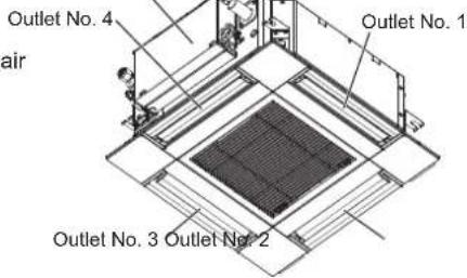
- "Outlet No." is the number given to each outlet of air conditioner. (Refer to the right.)
- "Up/Down air direction" is the direction (angle) to fix.
Horizontal airflow
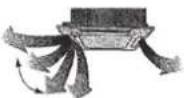
Downward
Remote controller setting
The airflow direction of this outlet is controlled by the airflow direction setting of remote controller.
Fixed setting
The airflow direction of this outlet is fixed in particular direction.
* When it is cold because of direct airflow, the airflow direction can be fixed horizontally to avoid direct airflow.
Electric component box
Note:
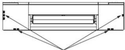
The outlet No. is indicated by the number of grooves on both ends of each air outlet. Set the air direction while checking the information shown on the remote controller display.
natural_image
Pure technical diagram showing symmetrical geometric shapes with arrows indicating direction (no text or symbols)Air outlet identification marks
7. Electrical work
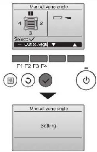
flowchart
graph TD
    A["Manual vane angle"] --> B["Select: ✓ Outlet Angle"]
    B --> C["F1 F2 F3 F4"]
    C --> D["Control knob with icon"]
    C --> E["Reset button with checkmark"]
    C --> F["Reset button with power symbol"]
    D --> G["↓"]
    E --> G
    F --> G
    G --> H["Manual vane angle"]
    H --> I["Setting"]
If all outlets are selected, will be displayed the next time the unit goes into operation.
Navigating through the screens
• To go back to the Main menu.....[MENU] button
• To return to the previous screen .....[RETURN] button
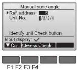
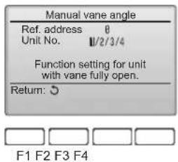
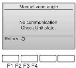
The current vane setting will appear.
Select the desired outlets from 1 through 4 with the [F1] or [F2] button.
- Outlet: "1", "2", "3", "4", and "1, 2, 3, 4, (all outlets)"
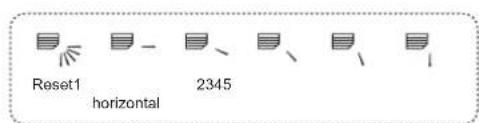
Press the [F3] or [F4] button to go through the option in the order of "No setting (reset)", "Step 1", "Step 2", "Step 3", "Step 4", "Step 5", and "Draft reduction*".
Select the desired setting.
■ Vane setting
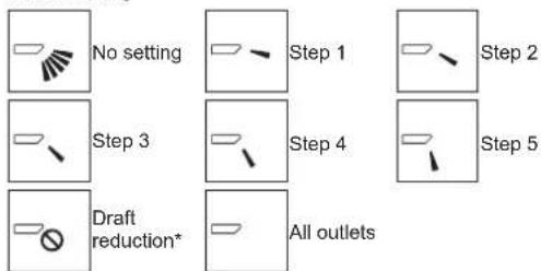
flowchart
graph TD
    A["No setting"] --> B["Step 1"]
    B --> C["Step 2"]
    D["Step 3"] --> E["Step 4"]
    E --> F["Step 5"]
    G["Draft reduction*"] --> H["All outlets"]
* Draft reduction
The airflow direction for this setting is more horizontal than the airflow direction for the "Step 1" setting in order to reduce a drafty feeling. The draft reduction can be set for only 1 vane.
Press the [SELECT] button to save the settings.
A screen will appear that indicates the setting information is being transmitted.
The setting changes will be made to the selected outlet.
The screen will automatically return to the one shown above (step 4) when the transmission is completed.
Make the settings for other outlets, following the same procedures.
Confirmation procedure
① First, confirm by setting "Ref. address" to 0 and "Unit No." to 1.
- Move the cursor to "Ref. address" or "Unit No." with the [F1] button to select.
- Select the refrigerant address and the unit number for the units to whose vanes are to be fixed, with the [F2] or [F3] button, and press the [SELECT] button.
• Ref. address: Refrigerant address - Unit No.: 1, 2, 3, 4
Press the [F4] button to confirm the unit.
② Change the "Unit No." in order and check each unit.
- Press the [F1] button to select "Unit No."
Press the [F2] or [F3] button to change the "Unit No." to the unit that you want to check, and then press the [F4] button. - After pressing the [F4] button, wait approximately 15 seconds, and then check the current state of the air conditioner.
→ The vane is pointing downward. → This air conditioner is displayed on the remote controller.
→ All outlets are closed. → Press the [RETURN] button and continue the operation from the beginning.
→ The messages shown to the left are displayed. → The target device does not exist at this refrigerant address. - Press the [RETURN] button to return to the initial screen.
③ Change the "Ref. address" to the next number.
- Refer to step ① to change the "Ref. address" and continue with the confirmation.
8. Test run
8.1. Before test run
▶ After completing installation and the wiring and piping of the Indoor and outdoor units, check for refrigerant leakage, looseness in the power supply or control wiring, wrong polarity, and no disconnection of one phase in the supply.
▶ Use a 500-volt megohmmeter to check that the resistance between the power supply terminals and ground is at least 1.0 MΩ.
▶ Do not carry out this test on the control wiring (low voltage circuit) terminals.
Warning:
Do not use the air conditioner if the insulation resistance is less than 1.0 MΩ.
8.2. Test run
8.2.1. Using wired remote controller
■ Make sure to read operation manual before test run. (Especially items to secure safety)
Step 1 Turn on the power.
| · Remote controller: The system will go into startup mode, and the remote controller power lamp (green) and "PLEASE WAIT" will blink. While the lamp and message are blinking, the remote controller cannot be operated. Wait until "PLEASE WAIT" is not displayed before operating the remote controller. After the power is turned on, "PLEASE WAIT" will be displayed for approximately 2 minutes. |
| · Indoor controller board: LED 1 will be lit up, LED 2 will be lit up (if the address is 0) or off (if the address is not 0), and LED 3 will blink. |
| · Outdoor controller board: LED 1 (green) and LED 2 (red) will be lit up. (After the startup mode of the system finishes, LED 2 will be turned off.) If the outdoor controller board uses a digital display, [-] and [-] will be displayed alternately every second. |
| If the operations do not function correctly after the procedures in step 2 and thereafter are performed, the following causes should be considered and eliminated if they are found. |
(The symptoms below occur during the test run mode. "Startup" in the table means the LED display written above.)
| Symptoms in test run mode | Cause | |
| Remote Controller Display | OUTDOOR BOARD LED Display< > indicates digital display. | |
| Remote controller displays “PLEASE WAIT”, and cannot be operated. | After “startup” is displayed, only green up. <00> | lights After power is turned on, “PLEASE WAIT” is displayed minutes during system startup. (Normal) |
| After power is turned on, “PLEASE WAIT” is displayed for 3 minutes, then error code is displayed. | After “startup” is displayed, green(once) red(once) blink alternately.< F1> | and Incorrect connection of outdoor terminal block (R, S, T and S1, S2, S3.) |
| After “startup” is displayed, green(once) red(twice) blink alternately.< F3, F5, F9> | and Outdoor unit’s protection devise connector is open. | |
| No display appears even when remote controller operation switch is turned on. (Operation I does not light up.) | After “startup” is displayed, green(twice) red(once) blink alternately.< EA. Eb> | Incorrect wiring between the indoor and outdoor unit (Polarity is wrong for S1, S2, S3.)Remote controller transmission wire short. |
| After “startup” is displayed, only green up. <00> | lights There is no outdoor unit of address 0. (Address is other than 0.)Remote controller transmission wire open. | |
| Display appears but soon disappears even when remote controller is operated. | After “startup” is displayed, only green up. <00> | lights After canceling function selection, operation is not possible for about 30 seconds. (Normal) |
Step 2 Switch the remote controller to "Test run".
① Select "Test run" from the Service menu, and press the [SELECT] button. (Fig. 8-1)
② Select "Test run" from the Test run menu, and press the [SELECT] button. (Fig. 8-2)
③ The test run operation starts, and the Test run operation screen is displayed.
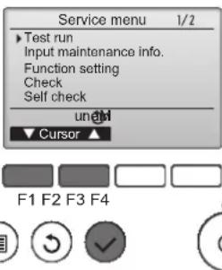
Fig. 8-1
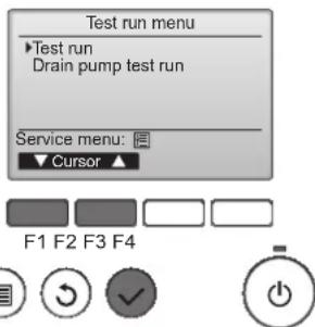
Fig. 8-2
Step 3 Perform the test run and check the airflow temperature and auto vane.
① Press the [F1] button to change the operation mode. (Fig. 8-3)
Cooling mode: Check that cool air blows from the unit.
Heating mode: Check that warm air blows from the unit.
② Press the [SELECT] button to display the Vane operation screen, and then press the [F1] and [F2] buttons to check the auto vane. (Fig. 8-4)
Press the [RETURN] button to return to the Test run operation screen.
If the vanes do not move, check that the junction wire connectors are connected securely and the connector colors match.
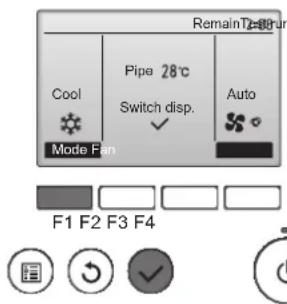
Fig. 8-3
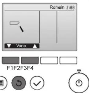
Fig. 8-4
Step 4 Confirm the operation of the outdoor unit fan.
The speed of the outdoor unit fan is controlled in order to control the performance of the unit. Depending on the ambient air, the fan will rotate at a slow speed and will keep rotating at that speed unless the performance is insufficient. Therefore, the outdoor wind may cause the fan to stop rotating or to rotate in the opposite direction, but this is not a problem.
8. Test run
Step 5 Stop the test run.
① Press the [ON/OFF] button to stop the test run. (The Test run menu will appear.)
Note: If an error is displayed on the remote controller, see the table below.
If the unit is operated continuously during a test run, the unit stops after 2 hours.
[Output pattern A] Errors detected by indoor unit
| Wireless remote controller | Wired remote controller | Symptom Remark | |
| Beeper sounds/OPERATION INDICATOR lamp blinks (Number of times) | Check code | ||
| 1 P1 Intake sensor error | |||
| 2 | P2 Pipe (TH2) sensor error | ||
| P9 Pipe (TH5) sensor error | |||
| 3 E6, E7 Indoor/outdoor unit communication error | |||
| 4 P4 Drain sensor error / Float switch connector open | |||
| 5 | P5 Drain pump error | ||
| PA Forced compressor error | |||
| 6 P6 Freezing/Overheating protection operation | |||
| 7 EE Communication error between indoor and outdoor units | |||
| 8 P8 Pipe temperature error | |||
| 9 E4 Remote controller signal receiving error | |||
| 10 — — | |||
| 11 | PB (Pb) | Indoor unit fan motor error | |
| 12 FB (Fb) | Indoor unit control system error (memory error, etc.) | ||
| 14 PL Refrigerant circuit abnormal | |||
| No sound | E0, E3 Remote controller transmission error | ||
| No sound | E1, E2 Remote controller control board error | ||
| No sound | — — — | No corresponding | |
[Output pattern B] Errors detected by unit other than indoor unit (outdoor unit, etc.)
| Wireless remote controller | Wired remote controller | Symptom Remark | |
| Beeper sounds/OPERATION INDICATOR lamp blinks (Number of times) | Check code | ||
| 1 | E9 | Indoor/outdoor unit communication error (Transmitting error) (Outdoor unit) | For details, check the LED display of the outdoor controller board. |
| 2 | UP | Compressor overcurrent interruption | |
| 3 | U3, U4 | Open/short of outdoor unit thermistors | |
| 14 | PL or Others | Abnormality of refrigerant circuit or other errors |
*1 If the beeper does not sound again after the initial 2 beeps to confirm the self-check start signal was received and the OPERATION INDICATOR lamp does not come on, there are no error records.
*2 If the beeper sounds 3 times continuously "beep, beep, beep (0.4 + 0.4 + 0.4 sec.)" after the initial 2 beeps to confirm the self-check start signal was received, the specified refrigerant address is incorrect.
- On wireless remote controller
The continuous buzzer sounds from receiving section of indoor unit.
Blink of operation lamp
- On wired remote controller
Check code displayed in the LCD.
- Refer to the following tables for details on the check codes. (Wireless remote controller)
[Output pattern A]

flowchart
graph LR
    A["Beep"] --> B["Beep 1st"]
    B --> C["Beep 2nd"]
    C --> D["Beep 3rd"]
    D --> E["Beep nth"]
    E --> F["Beep 1st"]
    F --> G["Beep 2nd"]
    G --> H["Repeated"]

    I["Self-check starts (Start signal received)"] --> J["Off Approx. 2.5 sec."]
    J --> K["On 0.5 sec."]
    K --> L["On 0.5 sec."]
    L --> M["On 0.5 sec."]
    M --> N["Off Approx. 2.5 sec."]
    N --> O["On 0.5 sec."]
    O --> P["On 0.5 sec."]

    Q["Number of blinks/beeps in pattern indicates the check code in the following table (i.e., n=5 for 'P5'')"]
    R["Number of blinks/beeps in pattern indicates the check code in the following table"]
[Output pattern B]

flowchart
graph LR
A["Beep"] --> B["Self-check starts (Start signal received)"]
B --> C["Beep 1st, 2nd, 3rd"]
C --> D["Beep nth, On 0.5 sec., Off Approx. 2.5 sec."]
D --> E["Beep 1st, 2nd, ... Repeated"]
E --> F["Beep 0.5 sec., On 0.5 sec."]
F --> G["Beep 0.5 sec., On Approx. 3 sec."]
G --> H["Beep 0.5 sec., On Approx. 3 sec."]
H --> I["Beep 0.5 sec., On 0.5 sec."]
I --> J["Beep 0.5 sec., On Approx. 3 sec."]
J --> K["Beep 0.5 sec., On Approx. 3 sec."]
K --> L["Beep 0.5 sec., On Approx. 3 sec."]
L --> M["Beep 0.5 sec., On Approx. 3 sec."]
M --> N["Beep 0.5 sec., On Approx. 3 sec."]
N --> O["Beep 0.5 sec., On Approx. 3 sec."]
O --> P["Beep 0.5 sec., On Approx. 3 sec."]
P --> Q["Beep 0.5 sec., On Approx. 3 sec."]
Q --> R["Beep 0.5 sec., On Approx. 3 sec."]
R --> S["Beep 0.5 sec., On Approx. 3 sec."]
S --> T["Beep 0.5 sec., On Approx. 3 sec."]
T --> U["Beep 0.5 sec., On Approx. 3 sec."]
U --> V["Beep 0.5 sec., On Approx. 3 sec."]
V --> W["Beep 0.5 sec., On Approx. 3 sec."]
W --> X["Beep 0.5 sec., On Approx. 3 sec."]
X --> Y["Beep 0.5 sec., On Approx. 3 sec."]
Y --> Z["Beep 0.5 sec., On Approx. 3 sec."]
Z --> AA["Beep 0.5 sec., On Approx. 3 sec."]
AA --> AB["Beep 0.5 sec., On Approx. 3 sec."]
AB --> AC["Beep 0.5 sec., On Approx. 3 sec."]
AC --> AD["Beep 0.5 sec., On Approx. 3 sec."]
AD --> AE["Beep 0.5 sec., On Approx. 3 sec."]
AE --> AF["Beep 0.5 sec., On Approx. 3 sec."]
AF --> AG["Beep 0.5 sec., On Approx. 3 sec."]
AG --> AH["Beep 0.5 sec., On Approx. 3 sec."]
AH --> AI["Beep 0.5 sec., On Approx. 3 sec."]
AI --> AJ["Beep 0.5 sec., On Approx. 3 sec."]
AJ --> AK["Beep 0.5 sec., On Approx. 3 sec."]
AK --> AL["Beep 0.5 sec., On Approx. 3 sec."]
AL --> AM["Beep 0.5 sec., On Approx. 3 sec."]
AM --> AN["Beep 0.5 sec., On Approx. 3 sec."]
AN --> AO["Beep 0.5 sec., On Approx. 3 sec."]
AO --> AP["Beep 0.5 sec., On Approx. 3 sec."]
AP --> AQ["Beep 0.5 sec., On Approx. 3 sec."]
AQ --> AR["Beep 0.5 sec., On Approx. 3 sec."]
AR --> AS["Beep 0.5 sec., On Approx. 3 sec."]
AS --> AT["Beep 0.5 sec., On Approx. 3 sec."]
AT --> AU["Beep 0.5 sec., On Approx. 3 sec."]
AU --> AV["Beep 0.5 sec., On Approx. 3 sec."]
AV --> AW["Beep 0.5 sec., On Approx. 3 sec."]
AW --> AX["Beep 0.5 sec., On Approx. 3 sec."]
AX --> AY["Beep 0.5 sec., On Approx. 3 sec."]
AY --> AZ["Beep 0.5 sec., On Approx. 3 sec."]
AZ --> BA["Beep 0.5 sec., On Approx. 3 sec."]
BA --> BB["Beep 0.5 sec., On Approx. 3 sec."]
BB --> BC["Beep 0.5 sec., On Approx. 3 sec."]
BC --> BD["Beep 0.5 sec., On Approx. 3 sec."]
BD --> BE["Beep 0.5 sec., On Approx. 3 sec."]
BE --> BF["Beep 0.5 sec., On Approx. 3 sec."]
BF --> BG["Beep 0.5 sec., On Approx. 3 sec."]
BG --> BH["Beep 0.5 sec., On Approx. 3 sec."]
BH --> BI["Beep 0.5 sec., On Approx. 3 sec."]
BI --> BJ["Beep 0.5 sec., On Approx. 3 sec."]
BJ --> BK["Beep 0.5 sec., On Approx. 3 sec."]
BK --> BL["Beep 0.5 sec., On Approx. 3 sec."]
BL --> BM["Beep 0.5 sec., On Approx. 3 sec."]
BM --> BN["Beep 0.5 sec., On Approx. 3 sec."]
BN --> BO["Beep 0.5 sec., On Approx. 3 sec."]
BO --> BP["Beep 0.5 sec., On Approx. 3 sec.<br>Number of blinks/beeps in pattern indicates the check code in the following table (i.e., n=5 for "U2")"]
See the table below for the details of the LED display (LED 1, 2, and 3) on the indoor controller board.
| LED1 (microcomputer power supply) | Indicates whether control power is supplied. Make sure that this LED is always lit. |
| LED2 (remote controller power supply) | Indicates whether power is supplied to the wired remote controller. The LED is lit only for the indoor unit that is connected to the outdoor unit that has an address of 0. |
| LED3 (indoor/outdoor unit communication) | Indicates whether the indoor and outdoor units are communicating. Make sure that this LED is always blinking. |
8. Test run
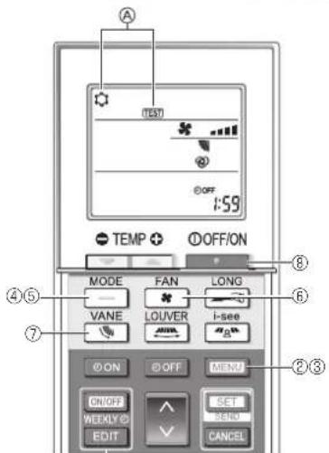
Fig. 8-5
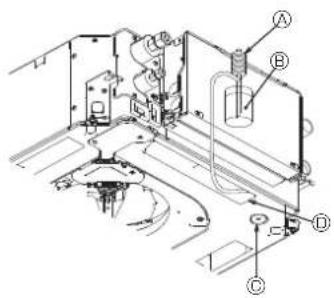
Ⓐ Water supply pump
⑧ Water (about 1000 cc)
© Drain plug
⑪ Pour water through outlet
- Be careful not to spray water into the drain pump mechanism.
Fig. 8-6
9. System control
Refer to the outdoor unit installation manual.
10. Installing the grille
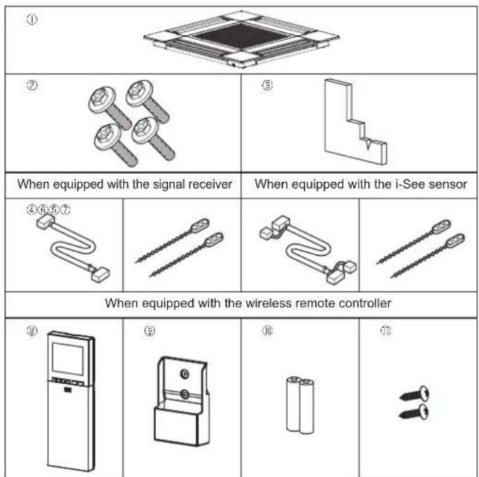
Fig. 10-1
8.2.2. Using the wireless remote controller
① Turn on the power to the unit at least 12 hours before the test run.
② Press the MENU button for 5 seconds. (Fig. 8-5) (Perform this operation when the remote controller display is turned off.)
③ Press the MENU button. Ⓐ [TEST] and the current operation mode are displayed. (Fig. 8-5)
④ Press the — button to activate cool mode, then check whether cool air is blown out from the unit.
⑤ Press the — button to activate heat mode, then check whether warm air is blown out from the unit.
⑥ Press the * button and check whether the fan speed changes.
⑦ Press the button and check whether the auto vane operates properly.
⑧ Press the button to stop the test run. (After two hours, a signal will be sent to stop the test run.)
Note:
- Point the remote controller towards the indoor unit receiver while following steps ③ to ⑥.
- It is not possible to perform the test run in FAN, DRY, or AUTO mode.
8.3. Self-check
■ Refer to the installation manual that comes with each remote controller for details.
8.4. Check of drainage (Fig. 8-6)
- Ensure that the water is being properly drained out and that no water is leaking from joints.
When electric work is completed.
• Pour water during cooling operation and check.
When electric work is not completed.
• Pour water during emergency operation and check.
* Drain pump and fan are activated simultaneously when single phase 230 V turned on to S1 and S2 on terminal block after the connector (SWE) on controller board in the electrical component box is set to ON.
Be sure to turn it back to the former state after work.
10.1. Check the grille accessories (Fig. 10-1)
• The grille should be supplied with the following accessories.
| Accessory name Q'ty Remark | |||
| 1 | Grille 1 625 × 625 (mm) | ||
| 2 | Screw with washer 4 M5 × 0.8 × 25 (mm) | ||
| 3 | Gauge | 1 | |
| 4 | Junction wire for signal receiver | 1 | Included when equipped with the signal receiver. |
| 5 | Junction wire for i-See sensor | Included when equipped with the i-See sensor. | |
| 6 | Fastener | 2 | Included when equipped with the signal receiver. |
| 7 | Fastener | 2 | Included when equipped with the i-See sensor. |
| 8 | Wireless remote controller | 1 | Included when equipped with the wireless remote controller. |
| 9 | Remote controller holder | 1 | Included when equipped with the wireless remote controller. |
| 10 | LR6 AA batteries 2 | Included when equipped with the wireless remote controller. | |
| 11 | 3.5 × 16 tapping screws | 2 | Included when equipped with the wireless remote controller. |
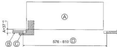
Fig. 10-2
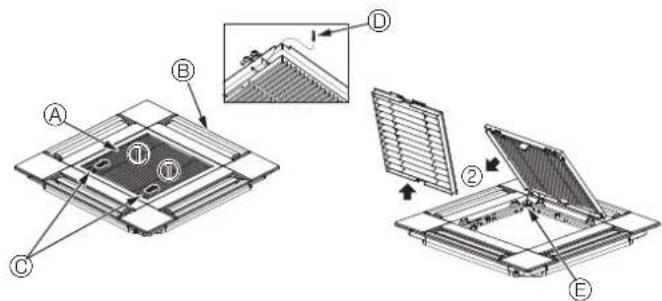
Fig. 10-3
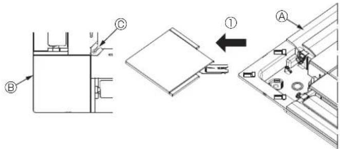
Fig. 10-4
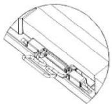
natural_image
Technical line drawing of a mechanical assembly with no visible text or symbols
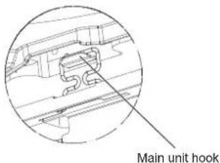
Fig. 10-5
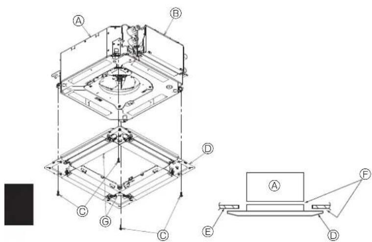
Fig. 10-7 Fig. 10-6
10.2. Preparing to attach the grille (Fig. 10-2)
- With the gauge supplied with this kit, adjust and check the positioning of the unit relative to the ceiling. If the unit is not properly positioned in the ceiling, there may be air leaks, condensation may form, or the up/down vanes may not operate correctly.
• Make sure that the opening in the ceiling is within the following tolerances: 576 × 576 - 610 × 610 - Make sure that step A is performed within 37-42 mm. Damage could result by failing to adhere to this range.
④ Main unit
® Ceiling
© Gauge (Accessory)
① Ceiling opening dimensions
10.2.1. Removing the intake grille (Fig. 10-3)
- Slide the levers in the direction indicated by the arrow ① to open the intake grille.
- Unlatch the hook that secures the grille.
* Do not unlatch the hook for the intake grille.
- With the intake grille in the "open" position, remove the hinge of the intake grille from the grille as indicated by the arrow ②.
⑧ Intake grille
⑧ Grille
© Intake grille levers
Grille hook
Hole for the grille's hook
10.2.2. Removing the corner panel (Fig. 10-4)
- Loosen the screw from the corner of the corner panel. Slide the corner panel as indicated by the arrow ① to remove the corner panel.
④ Grille
⑧ Corner panel
© Screw
10.3. Installing the grille
- Please pay attention because there is a restriction in the attachment position of the grille.
10.3.1. Temporarily installing the grille
- Align the screw holes in the corners of the grille with the screw mounting holes in the corners of the main unit, latch the two hooks on the grille onto the drain pan projections on the main unit, and temporarily hang the grille. (Fig. 10-5)
When installing the i-See sensor and signal receiver, place the junction wires in the connector box before temporarily hanging the grille.
Refer to 7.2.1. on page 10 to route the junction wires.
10.3.2. Securing the grille
- Secure the grille by tightening the four screws. (Fig. 10-6)
* Make sure that there are no gaps between the main unit and the panel or the panel and the ceiling. (Fig. 10-7)
④ Main unit
Electric component box
© Screw with washer (Accessory)
© Grille
① Ceiling
⑤ Make sure that there are no gaps.
© Temporarily hanging hooks on the panel
- When tightening the screw with captive washer Ⓗ, tighten it at a torque of 4.8 N·m or less. Never use an impact screwdriver.
It may result in parts damage.
• After tightening the screw, confirm that the two grille hooks (Fig. 10-5) are latched onto the hooks on the main unit.
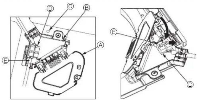
Fig. 10-9 Fig. 10-8
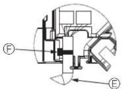
Fig. 10-10
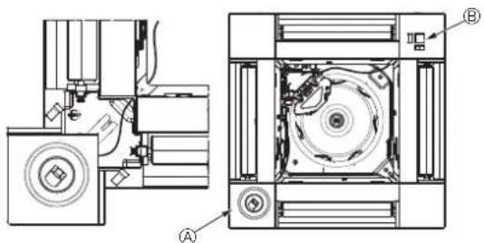
Fig. 10-11
natural_image
Technical line drawing of a mechanical assembly with an inset close-up showing a component detail (no text or symbols)Fig. 10-12
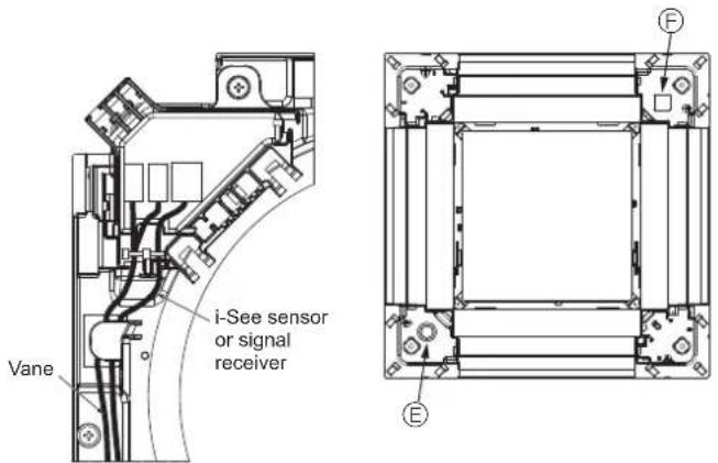
Fig. 10-13
10.3.3. Connecting the wires
① Remove the one screw securing the connector box cover, and then open the cover.
② Securely connect the junction wire connector of the vane motor and the panel vane motor wire connector in the connector box. (Fig. 10-8)
There are two vane motor connectors: one blue connector and one orange connector. Make sure that the connector colors match when connecting them.
③ Close the connector box cover.
When closing the connector box cover, slide the cover in the direction indicated by the arrow and make sure that the projection is firmly inserted. (Fig. 10-9)
② Connector box cover
⑤ Connector box
© Securing screw
© Junction connector
⑤ Wire connector for the vane motor
© Band
Caution:
- Place the band securing the panel vane motor wire in the connector box as shown in the diagram. (Fig. 10-10)
- When closing the connector box cover, make sure that the wires do not get pinched.
10.3.4. Wiring the i-See sensor corner panel and signal receiver
- Install the i-See sensor and signal receiver at the corners of the panel at the locations stamped with "o" or "□". (The positions may be reversed.)
- Route the i-See sensor and signal receiver wires through the square holes at the corners of the panel and install them.
- Connect the junction wire connector and the wire connectors of the i-See sensor and signal receiver in the connector box.
- Close the connector box cover.
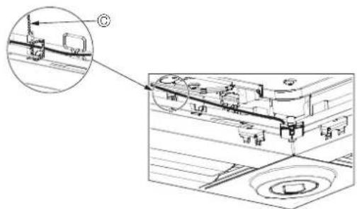
- Secure the i-See sensor and signal receiver wires to the panel with the fastener as shown in the diagram so that there is no slack in the wires, and then cut off the excess end of the fastener. (Fig.10-12)
- Place the i-See sensor and signal receiver wires to the inside of the flange on the panel.
- If the position of the i-See sensor was changed from the "o" position (E) to the "r" position (F), change the function settings. (Refer to page 13.)
Caution:
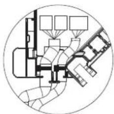
- Route the i-See sensor and signal receiver wires as shown in Fig. 10-13.
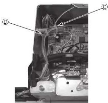
- Place the excess portions of the i-See sensor and signal receiver junction wires in the electric component box in the wire clip as shown in the diagram, and secure the wires together with the fastener. (Fig. 10-14) Make sure that the band securing the i-See sensor and signal receiver junction wires is positioned inside the connector box. (Fig. 10-15)
- If the vane motor connectors and signal receiver connector are connected incorrectly, the vanes will not move or communication with the remote controller will not be possible.
④ i-See sensor
⑤ Signal receiver
Fastener
Wire clip
⑤ "c" stamp: default i-See sensor position
© "☐" stamp: default signal receiver position
natural_image
Interior view of an electronic device showing exposed circuit board, wires, and components (no visible text or symbols)Fig. 10-14 Fig. 10-15
natural_image
Circular architectural floor plan with room layouts and structural elements (no text or labels)10. Installing the grille
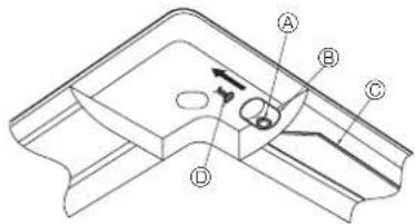
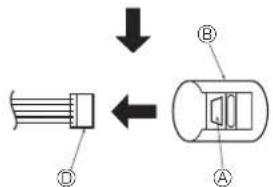
④ Button
© Vane motor
© Up/down vanes
Connector
Fig. 10-16
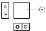
Signal receiver
Fig. 10-17
10.4. Locking the up/down airflow direction (Fig. 10-16)
The vanes of the unit can be set and locked in on up or down orientation depending upon the environment of use.
- Set according to the preference of the customer.
The operation of the fixed up/down vanes and all automatic controls cannot be performed using the remote controller. In addition, the actual position of the vanes may differ from the position indicated on the remote controller.
① Turn off the main power switch.
Injuries and or an electrical shock may occur while the fan of the unit is rotating.
② Disconnect the connector for the vane motor of the vent that you want to lock. (While pressing the button, remove the connector in the direction indicated by the arrow as shown in the diagram.) After removing the connector, insulate it with tape.
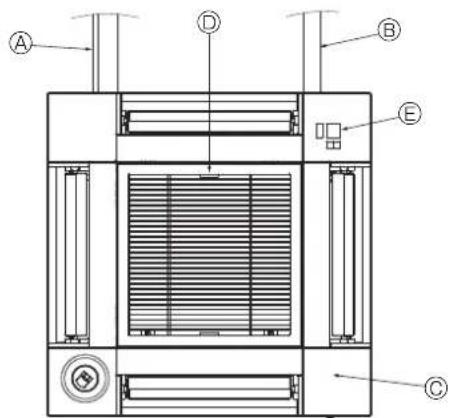
10.5. Installing the intake grille (Fig. 10-17)
- Perform the procedure that is described in "10.2. Preparing to attach the grille" in reverse order to install the intake grille and the corner panel.
④ Refrigerant piping of the main unit
⑥ Drain piping of the main unit
© Corner panel
⑥ Position of the levers on the intake grille when sent from the factory.
* Although the clips can be installed in any of four positions.
© Receiver
10.6. Check
- Make sure that there is no gap between the unit and the grille, or between the grille and the surface of the ceiling. If there is any gap between the unit and the grille, or between the grille and the surface of the ceiling, it may cause dew to collect.
• Make sure that the wires have been securely connected. - Check that all four vanes move. If two or four vanes do not move, refer to 10.3 and check the connections.
- For 3D i-See sensor corner panel, check the rotating movement. If the 3D i-See sensor does not rotate, review the procedure in "10.3. Installing the grille".
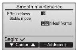
11. Easy maintenance function
Maintenance data, such as the indoor/outdoor unit's heat exchanger temperature and compressor operation current can be displayed with "Smooth maintenance".
* This cannot be executed during test operation.
* Depending on the combination with the outdoor unit, this may not be supported by some models.
①
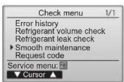
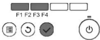
- Select "Service" from the Main menu, and press the [SELECT] button.
- Select "Check" with the [F1] or [F2] button, and press the [SELECT] button.
- Select "Smooth maintenance" with the [F1] or [F2] button, and press the [SELECT] button.
Select each item.
- Select the item to be changed with the [F1] or [F2] button.
- Select the required setting with the [F3] or [F4] button.
"Ref. address" setting ..... "0" - "15"
"Stable mode" setting ......"Cool" / "Heat" / "Normal"
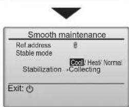
- Press the [SELECT] button, fixed operation will start.
* "Stable mode" will take approx. 20 minutes.
③
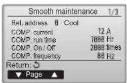
The operation data will appear.
The Compressor-Accumulated operating (COMP. run) time is 10-hour unit, and the Compressor-Number of operation times (COMP. On/Off) is a 100-time unit (fractions discarded)
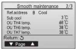
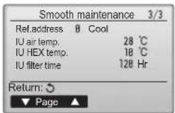
Navigating through the screens
• To go back to the Main menu.....[MENU] button
• To return to the previous screen ..... [RETURN] button
②

This product is designed and intended for use in the residential, commercial and light-industrial environment.
Please be sure to put the contact address/telephone number on this manual before handing it to the customer.
MITSUBISHI ELECTRIC CORPORATION
HEAD OFFICE: TOKYO BUILDING, 2-7-3, MARUNOUCHI, CHIYODA-KU, TOKYO 100-8310, JAPAN

- Air Conditioners
- SLZ-KF25, KF35, KF50, KF60VA3
- Contents
- Safety precautions
- Selecting the installation location
- Indoor unit
- Wireless remote controller mounting (For SLP-2FAL\*)
- Installation diagram
- Indoor unit (Fig. 3-1)
- Warning:
- Outdoor unit
- Installing the indoor unit
- Check the indoor unit accessories (Fig. 4-1)
- Ceiling openings and suspension bolt installation locations (Fig. 4-2)
- Caution:
- Installation of duct (in case of fresh air intake) (Fig. 4-3)
- Suspension structure (Give site of suspens strong structure) (Fig. 4-4)
- Unit suspension procedures (Fig. 4-5)
- Confirming the position of main unit and tightening the suspension bolts (Fig. 4-7)
- Precautions
- Refrigerant pipe (Fig. 5-1)
- Flaring work
- Pipe cutting (Fig. 5-2)
- Burrs removal (Fig. 5-3)
- Putting nut on (Fig. 5-4)
- Flaring work (Fig. 5-5)
- Refrigerant piping work
- Check (Fig. 5-6)
- Refrigerant and drainage piping locations (Fig. 5-7)
- Pipe connection (Fig. 5-8)
- Indoor unit
- Flare nut tightening
- Drainage piping work
- Drainage piping work (Fig. 6-1)
- Grouped piping
- Indoor unit power supplied from outdoor unit
- Indoor unit (Fig. 7-1) (Fig. 7-2) (Fig. 7-3)
- Work procedure
- Electrical work
- Installing the i-See sensor and signal receiver
- Remote controller
- Wired remote controller
- For wireless remote controller
- 3) Setting (Clock setting) (Fig. 7-8)
- 4) Initial setting
- 4-1. Switching to the initial setting mode
- 4-2. Changing the temperature unit Ⓜ
- 4-3. Changing the time display Ⓔ
- 4-4. Changing the AUTO mode ©
- 4-5. Changing the pair No. ⑪
- 4-6. Changing the backlight setting Ⓔ
- Function settings
- By wired remote controller
- By wireless remote controller (Fig. 7-16, Fig. 7-17, Fig. 7-18, Fig. 7-19)
- Function table
- How to set the fixed up/down air direction
- ■ Explanation of word
- Remote controller setting
- Fixed setting
- Note:
- Confirmation procedure
- Test run
- Before test run
- Test run
- Using wired remote controller
- Step 2 Switch the remote controller to "Test run".
- Step 3 Perform the test run and check the airflow temperature and auto vane.
- Step 4 Confirm the operation of the outdoor unit fan.
- Step 5 Stop the test run.
- System control
- Installing the grille
- Using the wireless remote controller
- Self-check
- Check of drainage (Fig. 8-6)
- When electric work is completed.
- Check the grille accessories (Fig. 10-1)
- Preparing to attach the grille (Fig. 10-2)
- Removing the intake grille (Fig. 10-3)
- Removing the corner panel (Fig. 10-4)
- Installing the grille
- Temporarily installing the grille
- Securing the grille
- Connecting the wires
- Wiring the i-See sensor corner panel and signal receiver
- Locking the up/down airflow direction (Fig. 10-16)
- Installing the intake grille (Fig. 10-17)
- Check
- Easy maintenance function
- Select each item.
- The operation data will appear.
- Navigating through the screens
Marke : MITSUBISHI
Modell : SLZ-KF25VAD
Kategorie : Klimaanlage