
RBC132 - Server APC - Kostenlose Bedienungsanleitung
Finden Sie kostenlos die Bedienungsanleitung des Geräts RBC132 APC als PDF.


| Produkttyp | Ersatzbatterie für USV |
| Marke | APC |
| Modell | RBC132 |
| Kategorie | Server (USV-Komponente) |
| Anwendungsbereich | Für APC Smart-UPS 1000/1500 |
| Batterietyp | Blei-Säure, versiegelt, wartungsfrei |
| Nennspannung | 24 V DC (2×12 V in Reihe) |
| Kapazität | 7,2 Ah (pro Batterie) / 172,8 Wh gesamt |
| Abmessungen (B×H×T) | 150 mm × 97 mm × 193 mm |
| Gewicht | 9,1 kg |
| Betriebstemperatur | 0 °C bis 40 °C |
| Lagertemperatur | -15 °C bis 45 °C |
| Lebensdauer | 3–5 Jahre (typisch) |
| Ladezeit | 4–6 Stunden |
| Anschlüsse | 2-poliger Stecker (kompatibel mit APC USV) |
| Kompatibilität | APC Smart-UPS SU, SUA, SMT, SMC Serien |
| Sicherheitsmerkmale | Überladeschutz, Tiefentladeschutz, temperaturkompensiertes Laden |
| Wartung | Wartungsfrei, kein Flüssigkeitsnachfüllen |
| Entsorgung | Fachgerecht über Batteriesammelstellen |
| Garantie | 2 Jahre |
| Installation | Plug-and-Play, einfacher Austausch |
Häufig gestellte Fragen - RBC132 APC
Benutzerfragen zu RBC132 APC
0 Frage zu diesem Gerät. Beantworten Sie die, die Sie kennen, oder stellen Sie Ihre eigene.
Eine neue Frage zu diesem Gerät stellen
Laden Sie die Anleitung für Ihr Server kostenlos im PDF-Format! Finden Sie Ihr Handbuch RBC132 - APC und nehmen Sie Ihr elektronisches Gerät wieder in die Hand. Auf dieser Seite sind alle Dokumente veröffentlicht, die für die Verwendung Ihres Geräts notwendig sind. RBC132 von der Marke APC.
BEDIENUNGSANLEITUNG RBC132 APC
Battery Cartridge Replacement
Back-UPS or BK (200 - 500 VA) and
Back-UPS Pro, BK Pro or SU (280 - 420 VA)
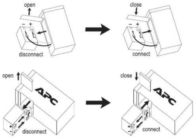
flowchart
graph TD
    A["open"] --> B["disconnect"]
    B --> C["close"]
    C --> D["connect"]
    D --> E["open"]
    E --> F["disconnect"]
    F --> G["close"]
    G --> H["connect"]
    H --> I["ABC"]
Back-UPS Pro USB (350, 500, and 650 VA)

natural_image
Diagram showing a device being processed from a box to a closed door, with arrows indicating motion (no text or symbols present)Back-UPS (1000 and 1400 VA)
Smart-UPS (450 - 1500 VA) and Smart-UPS XLBP
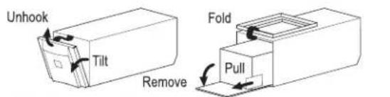
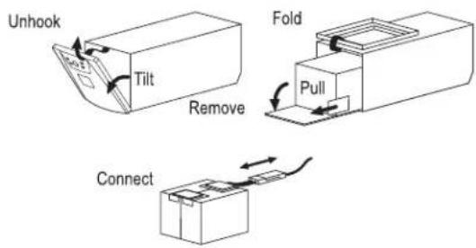

Back-UPS Office (250 - 500 VA)
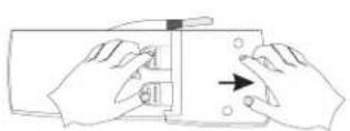
Press and Slide
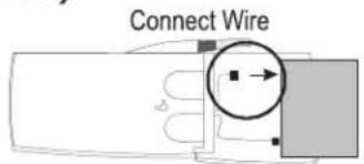
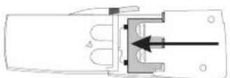
Close Cover
Back-UPS ES 350 and ES 500 and ES 550
remove screw
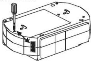
natural_image
Technical line drawing of a mechanical housing or enclosure with a screwdriver inserted (no text or symbols)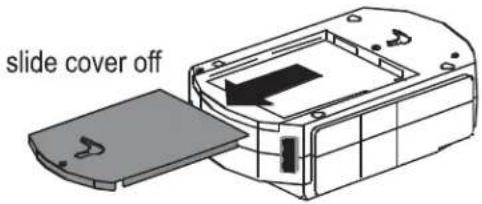
disconnect wires, replace with new battery and reconnect wires.
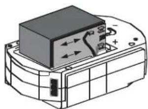
natural_image
Technical line drawing of a mechanical component with no visible text or symbolsBack-UPS ES 500
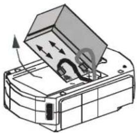
natural_image
Diagram of a printer or scanner with an open lid and internal components, showing directional arrows (no text or symbols)Back-UPS ES 350
Close cover and reinstall screw
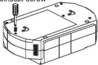
natural_image
Technical line drawing of a mechanical housing or enclosure with mounting holes and internal components (no text or symbols)Back-UPS ES 725
press release tabs and slide off cover
release tabs
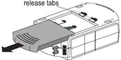
disconnect wires, replace with new battery and reconnect wires.
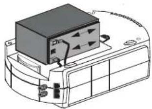
natural_image
Diagram of a device with a black box and cable, no visible text or symbolsclose cover
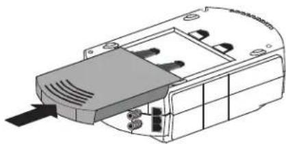
natural_image
Technical line drawing of a mechanical component with no visible text or symbolsBack-UPS 120V ES 350/450/550 and 220V ES 400/550/700
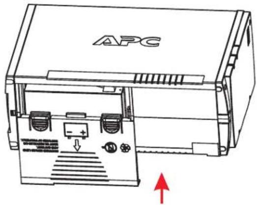
press release tabs and slide off cover
disconnect wires, replace with new battery and reconnect wires.
close cover
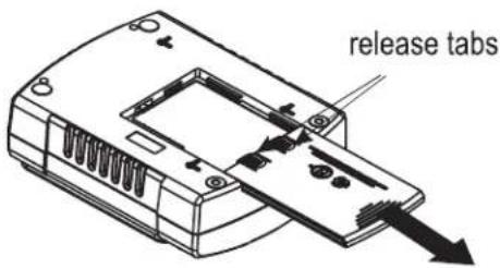
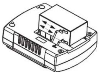
natural_image
Technical line drawing of a mechanical component with no visible text or symbols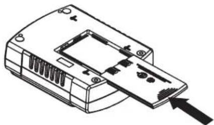
natural_image
Line drawing of a device casing with internal components and an arrow pointing to one end (no text or symbols)Smart-UPS Rackmount (all 5.25" tall models)
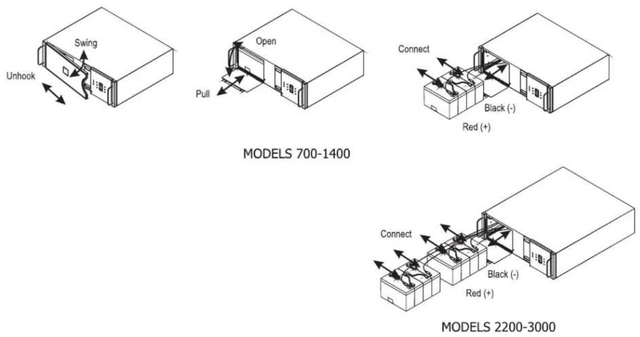
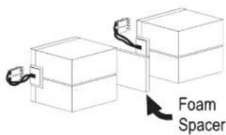
Smart-UPS Rackmount (all 8.75" tall models)
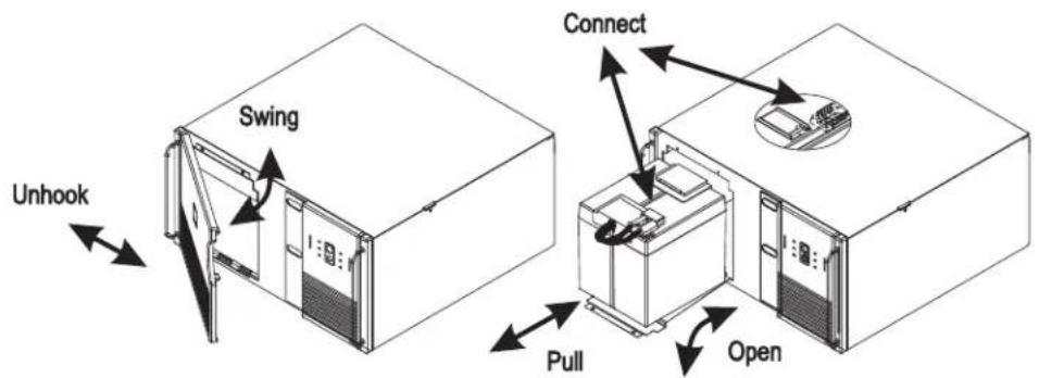
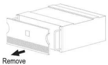
Smart-UPS Rackmount XL Battery Packs
natural_image
Technical line drawing of a mechanical component with a labeled 'Remove' arrow (no other text or symbols)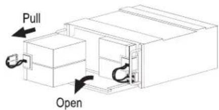
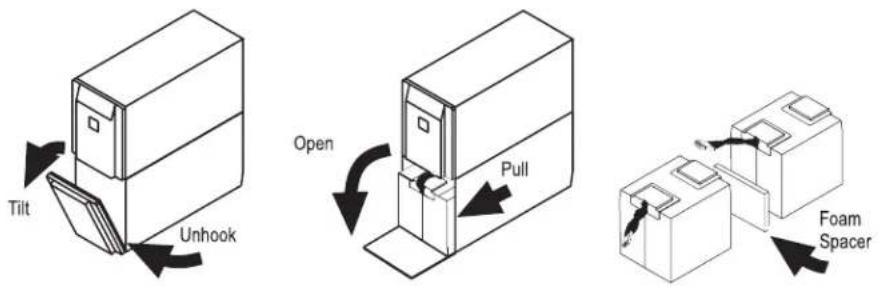
Smart-UPS (2200 and 3000 VA)
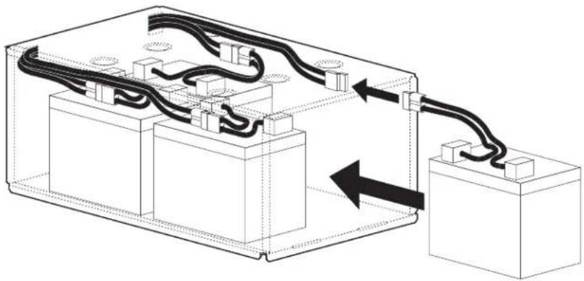
UXBP (24, 48, 48M)
natural_image
Technical diagram of an electrical enclosure with wiring and components, showing internal connections without any text or symbols.SmartCell XR
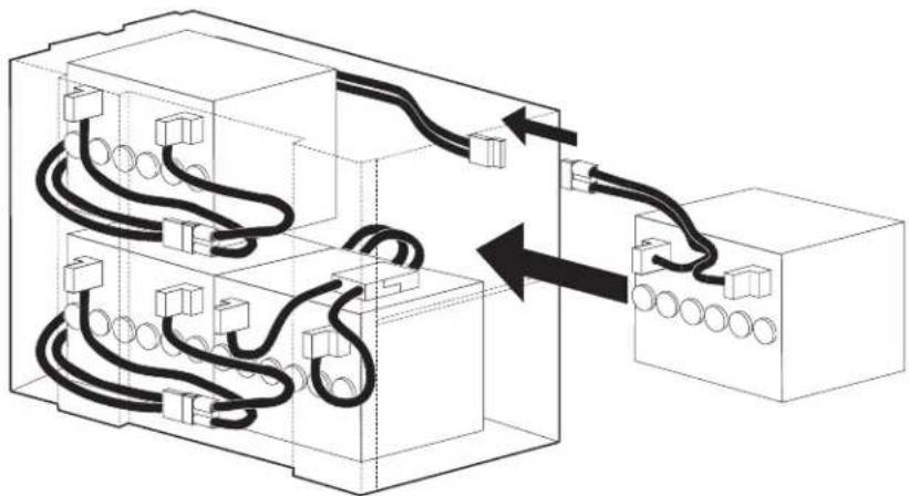
natural_image
Diagram of electrical wiring connections between two blocks, showing cable routing and terminal connections (no text or labels)Dispose

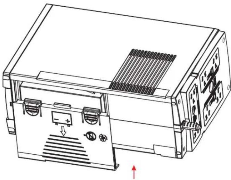
Back-UPS BR1000-CH
1 PRESS RELEASE TABS AND SLIDE OFF BATTERY DOOR.
3 REPLACE THE NEW BATTERY AND CONNECT THE WIRES.
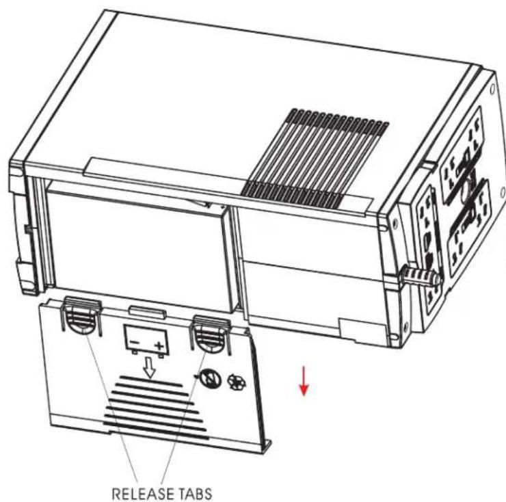
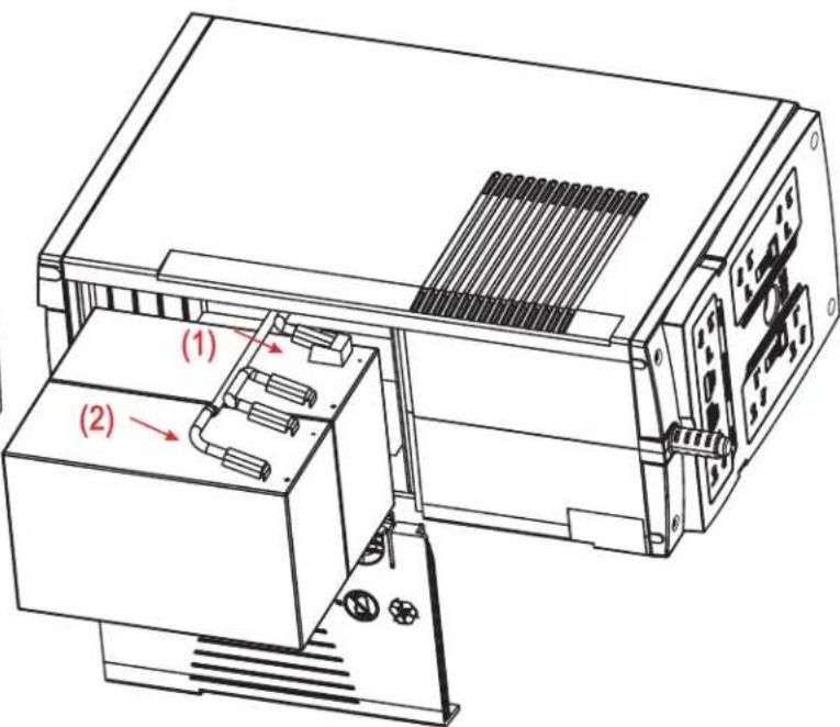
2 DISCONNECT THE BATTERY WIRES.
4 CLOSE THE BATTERY DOOR.
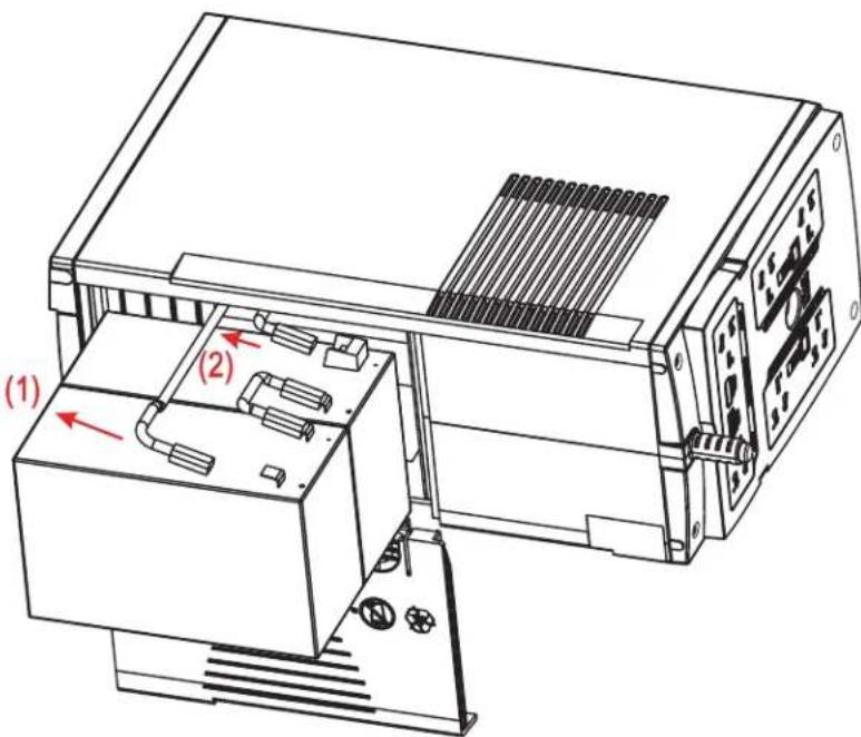
natural_image
Technical line drawing of an electronic device with ports and a panel, showing internal components and directional arrows (no text or symbols)990-0179J
Back-UPS BX900R/BX1200R/DL1000VNT BR1100CI/BR1100CI-RS/BR1100CI-AS/BR1100CI-IN BX1300LCD/BX1500LCD/BN1250LCD
1 PRESS RELEASE TABS AND SLIDE OFF BATTERY DOOR.
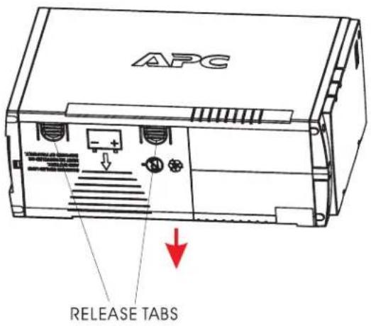
3 REPLACE THE NEW BATTERY AND CONNECT THE WIRES.
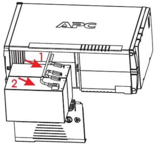
2 DISCONNECT THE BATTERY WIRES.
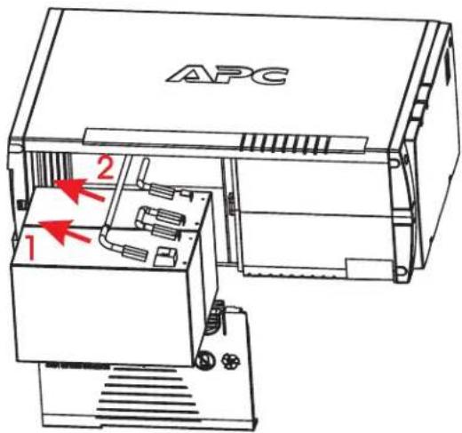
4 CLOSE THE BATTERY DOOR.



Marke : APC
Modell : RBC132
Kategorie : Server