
CG-A9 - Alarm Chuango - Kostenlose Bedienungsanleitung
Finden Sie kostenlos die Bedienungsanleitung des Geräts CG-A9 Chuango als PDF.


| Produkttyp | PSTN/Tastenfeld-Alarmsystem |
| Modell | Chuango CG-A9 |
| Abmessungen der Zentrale | 190 × 137 × 38 mm |
| Stromversorgung | Eingang DC 12 V, 500 mA (Netzteil); Backup: 4× AA 1,2 V Ni-MH Akku (800 mAh) |
| Standby-Stromverbrauch | ≤ 30 mA |
| Alarm-Stromverbrauch | ≤ 280 mA |
| Akku-Backup | Bis zu 8 Stunden |
| Interner Sirenenton | 110 dB (einstellbar: laut, leise, stumm) |
| Funkfrequenz | 315 MHz oder 433,92 MHz (±75 kHz) |
| Anzahl anschließbarer Komponenten | Bis zu 10 Fernbedienungen, 50 Funkmelder |
| Alarmnummern | 6 Nutzernummern + 2 CMS-Nummern (ADEMCO CID) |
| Verzögerungen | Ein-/Ausgangsverzögerung programmierbar (0–99 s) |
| Fernbedienung per Telefon | Aktivierbar mit Sprachansage (2–9 Klingeltöne) |
| Gehäusematerial | ABS-Kunststoff |
| Betriebstemperatur | −10 °C bis +55 °C |
| Luftfeuchtigkeit | ≤ 80 % (nicht kondensierend) |
| Lieferumfang | Zentrale, 2 Fernbedienungen, Tür-/Fensterkontakt, PIR-Bewegungsmelder (haustierimmun bis 25 kg), Netzteil, Telefonkabel, Wandhalter, Schrauben, Klebeband |
| Wartung | Batterien bei Bedarf wechseln, Gehäuse mit trockenem Tuch reinigen, monatlicher Funktionstest |
| Sicherheitsfunktionen | Sabotageschutz (Tamper), Überfalltaste (SOS), Leitungsalarm, 24-Stunden-Zone |
| Ersatzteile & Reparatur | Fernbedienungen, Tür-/Fensterkontakt, PIR-Melder, Akkus (AA Ni-MH) und Netzteil erhältlich; Reparatur nur durch Fachhändler |
Häufig gestellte Fragen - CG-A9 Chuango
Benutzerfragen zu CG-A9 Chuango
0 Frage zu diesem Gerät. Beantworten Sie die, die Sie kennen, oder stellen Sie Ihre eigene.
Eine neue Frage zu diesem Gerät stellen
Laden Sie die Anleitung für Ihr Alarm kostenlos im PDF-Format! Finden Sie Ihr Handbuch CG-A9 - Chuango und nehmen Sie Ihr elektronisches Gerät wieder in die Hand. Auf dieser Seite sind alle Dokumente veröffentlicht, die für die Verwendung Ihres Geräts notwendig sind. CG-A9 von der Marke Chuango.
BEDIENUNGSANLEITUNG CG-A9 Chuango


Security Alarm System
Printed in Hong China
PA: A9-UM-EN-V1.0
© 2014 Chuango. All rights reserved.
PSTN/Keypad Security Alarm System

Please read this user manual carefully before using. Please kindly keep this user manual for your reference when necessary.
Features
• 100% wireless configuration, D.I.Y. installation
• Convenient operation by remote control and keypad
• Support 10 remote controls, 50 wireless sensors
• Built-in 1,000,000 RF codes combination maintains high reliability
- Mute operation by remote control at late night
• Built-in 110dB siren, deterring intruder on site
• Support entry / exit delay
• Voice prompt during phone remote control
• Simple expansion of accessories by automatic learning
- Remote arm, disarm and monitor by phone operation
• Store 6 alarm phone numbers and 2 ADEMCO CID CMS numbers
• Built-in 4 pcs of 1.2V 800mAh Ni-MH batteries, enables 8-hour standby
Table of Contents
| Included Accessories | 1~2 |
| Control Panel Layout | 3~4 |
| Alarm LED Indication | 4 |
| Preparation before Use | 5~6 |
| Control Panel Operation | 7~8 |
Arm(Away Arm)
Disarm
Home Mode(Part Arm)
Emergency Call
System Settings 9\~15
Enter Setup State
Siren Ringing Time
Exit Delay Time
Entry Delay Time
Siren Volume
Remote Phone Control
Arm/Disarm Beeps for Wireless Siren
Linecut Alarm
Access Code
Reset
Alarm Phone Number Setup
Store Alarm Phone Numbers
Delete Alarm Phone Numbers
User ID
Uploading Arm/ Disarm Report to CMS Center
Contact ID Code and Contents
Phone Remote Control Operation 16
Remote Phone Control Instruction Table
Add / Delete Wireless Accessories 17
Add Wireless Accessories
Delete Wireless Accessories
Zone Setup of Wireless Accessories 18
System Setting List 19\~20
FAQ 21
Specifications 22
Wireless Remote Control 23\~25
Arm(Away arm)
Home Mode(Part Arm)
Disarm
Emergency Call
Arm/Disarm in Mute
Wireless Door/Window Contact 26\~29
Pet-Immune PIR Motion Detector 30\~38
Included Accessories
CG-A9 Control Panel x 1
The control panel is known as the "heart and brain" for alarm system, which is used for receiving and processing signals from wireless sensors and remote controls. Users can make settings freely with the keypad. In case of emergency, the panel rings on site and dialis the pre-stored alarm phone numbers automatically. When users pick up the phone, they are able to hear prompt voice and choose to monitor on site or disarm the system.


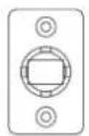
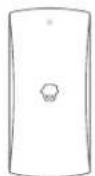

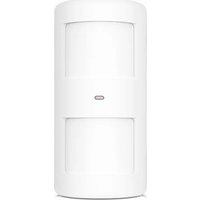
Pet-Immnue PIR Motion Detector x 1 Bracket x 1
The wireless PIR Motion Detector is an intelligent passive infrared motion sensor, designed to detect human movement within an approximate range of 6 to 8 meters from the detector. The detector includes fuzzy logic to minimize false alarms from unwanted heat sources. With power saving feature, the detector will enter sleeping mode after the second activation within 3 minutes to save power.
Wireless Door/Window Contact x 1
The Door/window contact can be installed on doors, windows and any other objects that open and close. The sensor transmits signals to the control panel when a magnet mounted near the sensor is moved away.

Wireless Remote Control x 2
The remote control is compact and portable; it is convenient to carry it to arm, disarm, and partially arm the alarm system and also send an emergency call.

AC Adapter x 1
Supply power to the control panel via it. In case of power failure, four backup batteries in the panel will support 8-hour working time.

Telephone Cable x 1
Connect the control panel and telephone
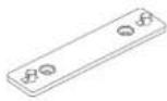
Wall-mounted bracket for control panel

Screws

Double-sided tape for Door/Window Contact

User Manual
Control Panel Layout
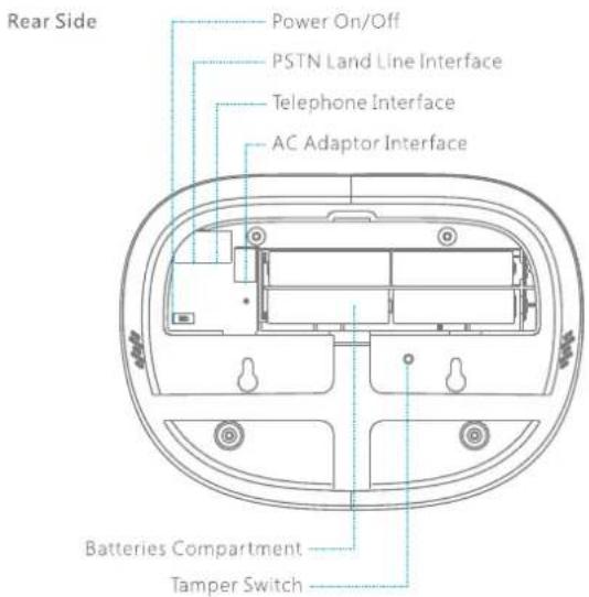
Front Side

Alarm LED Indication
| Alarm Type | Indicator State |
| Tamper Alarm | Setup/Wireless Signal LED Indicator, Arm LED Indicator and all Zone LED Indicators will flash |
| Normal Zone Alarm | The triggered Zone LED Indicator will flash |
| 24-hour Zone Alarm | All the Zone LED Indicators will flash |
| Emergency Call | Arm LED Indicator and all Zone LED Indicators will flash |
Preparation before Use
1. Power on
③ Plug the output connector of AC adapter into the adapter interface of control panel.
② Plug the AC adapter to wall power socket,
③ Turn the power switch from OFF to ON.

2. Connect PSTN Land Line
A9 is a PSTN alarm system which will auto dial the pre-stored phone number when the system detects intruders. Please be sure the panel has connected to PSTN land line to ensure safety.
① Connect the PSTN Land Line provided by fixed telephone line operator to the PSTN Land Line interface on the panel.
② Connect one end of provided telephone cable to the telephone interface on the panel, the other end to the telephone. (It's workable for telephone to make phone call after connecting the cable to the panel, if no need to use telephone for daily communication, please ignore this connection)

3. Installation
Fix the wall mounting bracket on the wall with screws. Wedge the panel on the bracket, make sure they fit well.
Control Panel Operation
Arm (Away Arm)


Press the [Arm] button on the control panel, the system enters Arm State when one beep is heard and the Arm LED Indicator lights on.
Note!
If Exit Delay is activated, all zones except the 24-hour zone will enter Arm state after the set delay time.
Disarm


Input user code or admin code first, then press the [Disarm] button, the system enters Disarm state when one beep is heard and the Arm LED Indicator goes out.
Home Mode (Part Arm)


Press the [Home Mode ⚙] button on the control panel, the Arm LED Indicator flashes every 2 seconds after one beep is heard. Now, all the sensors in [B, C, D, E, F and 24H] zones are armed except Zone A. All the sensors in Zone A are disarmed for users' so users can move freely at home.
Emergency Call


In any condition, once [SOS] panic button on the control panel is pressed, the system immediately goes into emergent alarming state with siren hooting, meanwhile the panel will auto dial pre-stored alarm phone numbers.
System Settings
Enter Setup State
Input [admin code], press [#] button, the keypad is activated after one beep. Press [3] button, the control panel enters setup state after another beep and the Setup LED Indicator lights on.
Note
Under setup state, press [Esc] button on the control panel, the system exit setup state after 2 beeps are heard and the Setup LED Indicator goes out
The control panel will give out 3 beeps and the Setup LED Indicator will flash 3 times for incorrect operation.
1. Siren Ringing Time
Enter setup state, input *1*1-9*
The setup succeeded after one long beep.
Note: "1-9" refers to 1-9 minutes. Default setting: 5 minutes.
2. Exit Delay Time
Exit delay is set to leave time for user to exit and then arm the system in the set time.
Enter setup state, input *2*00-99*
The setup succeeded after one long beep.
Note: "00-99" refers to 0-99 seconds. Default setting: 0 seconds, no delay.
When exit delay time is set, press the [Arm] button, the control panel will beep every 2 seconds reminding users to leave, the reminding rhythm will speed up in the last 15 seconds.
3. Entry Delay Time
Entry delay is set to leave time for user to disarm the system when sensor is triggered.
Enter setup state, input * 3 * 00 - 99*
The setup succeeded after one long beep.
Note: '00\~99" refers to 0-99 seconds. Default setting: 0 seconds, no delay.
Special tips!
Once the function is programmed, when you arm the system, the alarm time of all the triggered sensors will be delayed accordingly except emergency call and the sensors in 24H zone. Within the delay time, the panel beeps once every 2 seconds to remind the user to disarm the system. The reminding rhythm will speed up in the last 15 seconds. If the user fails to disarm the system, the control panel will alarm and dial the pre-stored phone numbers accordingly.
4. Siren Volume
Enter setup state, input *4*0-2*
The setup succeeded after one long beep.
Note: [0] = mute, [1] = Low, [2] = High.
Default setting: High volume
If siren volume is mute, when user operates the control panel by remote control.
no beep will be heard as well.
5. Remote Phone Control
User can set to enable or disable phone remote control function. On phone remote control, user can freely get access to the alarm system for operations such as arming, disarming, and on site monitoring by dialing the telephone no. of the alarm system.
Enable Phone Remote Control
Enter setup state, input *5*2-9*
The setup succeeded after one long beep.
Note: "2-9" refers to the phone ringing times when you call the phone no. of alarm system. Default setting: Remote phone control is disabled.
Disable Phone Remote Control
Enter setup state, input * 5 **
The setup succeeded after one long beep.
Special tips!
If user cannot remotely control the system by phone, please make sure the function of Remote Phone Control is enabled.
6. Arm/Disarm Beep for Wireless Siren
Enter setup state, input *6*0* or *6*1*
The setup succeeded after one long beep.
Note: [0] = Wireless siren does not beep when arming or disarming the alarm system; [1] = Wireless siren beeps when arming or disarming the alarm system. Default setting: With beep.
7. Linecut Alarm
Enter setup state, input *7*0* or *7*1*
The setup succeeded after one long beep.
Note! [0] = Disable linecut alarm function
[1] = Enable linecut alarm function
Default setting: Enabled.
8. User Code
Enter setup state, input *8* new user code *
The setup succeeded after one long beep.
Note: User code must be 4 digits, default setting is 1234.
9. Admin Code
Enter setup state, input *9* new admin code *
The setup succeeded after one long beep.
Note! Admin code must be 6 digits, default setting is 123456.
If users forgot admin code, please contact local distributors.
10. Reset
Enter setup state, input *0**
The setup succeeded after one long beep.
Note! All settings are restored to default, except the connected wireless accessories.
11. Store Alarm Phone Number
Enter setup state, input #1-8# phone number#
The setup succeeded after one long beep.
Note! The 1st to 6th phone numbers are for users' phone numbers. The 7th and the 8th phone numbers are for CMS (No need to set the phone numbers if the system is not connected the CMS)
If group extended telephone number is used, 0* or 9* should be added in front of the phone number.
Example: Store the 1st phone number as 12345678.
Enter setup state, input #1#0*12345678#
The setup succeeded after one long beep.
Note: When the system is alarming, the control panel will auto dial to pre-stored phone numbers in 3 turns. If user answered the call or make any dialing operation, the system will stop dialing other stored phone numbers.
12. Delete Alarm Phone Number
Enter setup state, input #1-8##
The setup succeeded after one long beep.
Note: 1-8 refers to the group of phone number to be deleted. Delete all existing alarm phone numbers: #0##
13. User ID
It is supplied by CMS center. After it is stored, CMS center can exactly know user's location according to the ID number.
Enter setup state, input *20*User ID*
The setup succeeded after one long beep.
Note: The user number must be 4 digits.
14. Uploading Arm/ Disarm Report to CMS Center
Enter setup state, input *21*0* or *21*1*
The setup succeeded after one long beep.
Note: [0] = Disable uploading arm/disarm report to CMS. [1] = Enable uploading arm/disarm report to CMS. Default setting: Disable uploading arm/disarm report to CMS.
- Contact ID Code and Contents
| Event Code | Event |
| 3401 | Arm |
| 1401 | Disarm |
| 1132 | PIR detector alarm |
| 1131 | Door contact alarm |
| 1100 | Emergency call |
| 3456 | Home mode (part arm) |
| 1137 | Control panel tamper alarm |
| 1144 | Sensor tamper alarm |
| 1140 | Normal zone alarm |
| 1133 | 24H zone alarm |
| 1384 | Sensor low battery |
| 1302 | Control panel low battery |
| 1301 | Control panel AC failure |
Phone Remote Control Operation
Method 1
When alarm system is triggered, the control panel will dial pre-stored user phone numbers. On answering, user could follow the voice prompt to make remote control accordingly. (See Instruction Table Below)
Method 2
User dials alarm system telephone no.; after getting through, alarm system will guide you to input access code.
Input access code (user code or admin code); Press [#].
Alarm system plays the voice prompt twice to explain the functions.
User chooses the related instruction to make remote control operation.
(See Instruction Table Below)
Note 1 Alarm system will hang up after 30 seconds with no operation.
Phone Remote Control Instruction Table
| Phone Buttons | Function | Explanation |
| Press [1] | Arm the system | Phone voice prompt "Arm Succeed" |
| Press [0] | Disarm the system | Phone voice prompt "Disarm Succeed" |
| Press [*] | Monitor on site | Press [*] to prolong monitor time |
| Press [9] | Turn on siren | Deter the intruders |
| Press [6] | Turn off siren | Stop siren ringing |
| Press [8] | Turn on relay | Available for the system with RS-1000 relay module |
| Press [5] | Turn off relay | |
| Press [#] | To exit phone remote control | Or hang up the phone |
Add/Delete Wireless Accessories
New purchased accessories must be connected with the control panel first before use.
Add Wireless Accessories
Input [admin code], press [#] button, the keypad is activated. Press [9] button, the Setup LED Indicator lights on, the panel enters learning state. Then trigger the wireless accessory once, the learning is successful after one beep is heard and the Setup LED Indicator goes out.
If two beeps are heard, it means the wireless accessory has been connected before. If another recoding is needed, press [9] button again and repeat the above operation.
Note! If there is no operation and the control panel does not receive any RF signals within 30 seconds after pressing the [9] button, the system will exit the learning state.
Delete Wireless Accessories
Input [admin code], press [#] button, the keypad is activated. Press down the [9] button until one long beep is heard, all the connected accessories are deleted.
Zone Setup of Wireless Accessories

Home Mode Zone


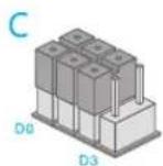
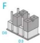
The door sensor is set at Zone C and the PIR motion detector is at Home Mode Zone (Zone A). Zones can be changed according to your requirements.
Once the zone setting is changed, the detector should be reconnected with the control panel.

24-H Zone
Note: In any condition, the system will alarm immediately once the detector in this zone is triggered. It is recommended to set smoke detector, gas detector and outdoor beam sensor at 24-H zone.
System Setting List
| Description | Operation Command | Functions | Remarks |
| Siren Ringing Time | × 1 × [1-9] × | [1~9]Refer to the minutes that the siren keeps alarming. User can program it to be 1~9 minutes | Default setting: 5 minutes. |
| Exit Delay Time | × 2 × [00-99] × | [00~99] Refer to the delayed time. User can program it to be 0~99 seconds | Default setting: No delay. |
| Entry Delay Time | × 3 × [00-99] × | [00~99] Refer to the delayed time. User can program to be 0~99 seconds. | Default setting: No delay. The value time is 00. |
| Siren Volume | × 4 × [0-2] × | [0] Mute, [1] Low Volume, [2] High Volume | Default setting: High Volume. The value is 2. |
| Enable Phone Remote Control | × 5 × [2-9] × | [2-9] refer to the ringing times of automatic answer | Default setting: Disabled. |
| Disable remote phone control | × 5 × × | ||
| Turn On/OH Arm /Disarm Beep for Wireless Siren | × 6 × [0/1] × | [0] Disable arm or disarm beep. [1] Enable arm or disarm beep. | Default setting: Enable |
| User Code | × 8 × new user code × | The user code must be 4 digits. | Default code: 1234 |
| Admin Code | × 9 × new admin code × | The admin code must be 6 digits. | Default code: 123456 |
| Reset | × 0 × × | Reset system to default setting. | The connected wireless accessories will not be affected. |
| User ID for CMS | × 20 × user ID × | The user number must be 4 digits. | No need to set if the system is not connected to CMS. |
| Uploading Arm or Disarm Report | × 21 × [0/1] × | [0] Disable uploading Arm or Disarm Report. [1] Enable uploading Arm or Disarm Report. | No need to set if the system is not connected to CMS. |
| Description | Operation Command | Functions | Remarks |
| Store Alarm Phone Number | #[1-8] phone number | Please refer to page 13 | [1~6] refer to users' telephone numbers [7~8] refer to phone numbers for CMS. No need to set the numbers if the system is not connected to CMS. |
| Delete alarm Phone Number | #[1-8] | Delete one of the phone numbers. | If no number is stored, the system will not dial for alarming |
| 0## | Delete all the phone numbers. | ||
| Exit Setup State | Press [Esc] button | The system will exit setup state after 2 beeps and the Setup LED indicator lights off |
FAQ
| Phenomena | Cause of Malfunction | Troubleshoot Method |
| The wireless accessory cannot work with the control panel. | The wireless working frequency is different. | Change a new wireless accessory with same working frequency. |
| Trigger the wireless sensor, but the alarm panel cannot work. | The wireless sensor was not connected to the control panel successfully. | Connect the sensor to the control panel once again. |
| The distance between the sensor and the control panel is too far. | position of the sensor to make sure it can work with control panel in right working distance. | |
| Cannot enter setup state after inputting password. | Only the admin code can program the control panel. The user code cannot work. | Input the correct admin code. |
| The control panel beeps once every 2 seconds after arm the system by remote control. | The Entry/ Exit Delay function has been enabled. | If this function is not needed, please disable the Entry/ Exit Delay function. |
| The Setup/Wireless Signal LED Indicator flashes frequently. | There exists same wireless signal nearby. | Change the installation position of the control panel, and then test it again. |
| Users cannot receive the phone call after the control panel is activated. | The control panel uses an extension for dialing. | 0 or 9 should be added before the dialing phone number. |
| The PIR motion detector cannot activate the control panel. | The control panel is in Home Mode. | Arm the control panel again. |
Specifications
Product Name
PSTN/Keypad Alarm System
Model No.
CG-A9
Power Supply
Input: DC 12V 500mA, 6Wh
Static Currenct
≤ 30mA
Alarm Currenct
≤ 280mA
Battery Backup
AA 1.2V Ni-MH rechargeable battery x 4 pcs
Internal Siren Volume
110dB (High volume)
Radio Frequency
315MHz or 433.92MHz (±75KHz)
Allowed Amount of Expandable Wireless Accessories
10 remote controls, 50 wireless sensors
Housing Material
ABS plastic
Operation Condition
Temperature: -10°C\~+55°C
Relative Humidity: ≤ 80% (Non-condensing)
Panel Size(LxWxH)
190×137×38mm
Wireless Remote Control

Arm (Away Arm)


Press the [Arm 🔊] button on the remote control, the system enters Arm state when one beep is heard and the Arm LED Indicator lights on.
Note! If Exit Delay is activated, all zones except the 24-hour zone will enter Arm state after the set delay time.
Disarm


Press the [Disarm ⚙] button on the remote control, the system enters Disarm state when two beeps are heard and the Arm LED Indicator goes out.
When alarm is activated, the siren will hoot. Press the [Disarm] button, the system is disarmed after two beeps are heard, and the Arm LED Indicator goes out. But the LED indicator of triggered zone keeps flashing for further checking. Press [Disarm] button again, all zone indicators go out.
Home Mode (Part Arm)

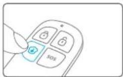
Press the [Home Mode] button on the remote control, the system enters Home Mode when one beep is heard and the Arm LED Indicator flashes every two seconds. From then on, all the sensors in [B, C, D, E, F and 24H] zones are armed except Zone A. Now all the sensors in Zone A are disarmed so that users can move freely at home.
Emergency Call
SOS

In any condition, once [SOS] panic button on the remote control is pressed the system immediately goes into emergent alarming state with siren hooting, meanwhile the panel will auto dial pre-stored alarm phone numbers.
Mute Mode


When arm or disarm the system, the control panel will beep once or twice. If siren beep is not needed, operation as follows:
Press and hold the [Stay 🔒] button on the remote control for 1 second, then press [Arm 🔒] or [Disarm 🔒] button within 3 seconds. The system is armed or disarmed in mute without disturbing other people.
Wireless Door/Window Contact
Features
The DWC-102 is a Door/Window Contact that can be installed on doors, windows, and any other objects that open and close. The sensor transmits signals to the control panel when a magnet mounted near the sensor is moved away. External input for wired accessory is available at the N/C interface. The tamper protection ensures that sabotage attempts to move the contact will result in an alarm activation.
Appearance

LED Indication
LED flashes once: Door/window is opened and transmitter sends signal to the control panel.
Flash once per 3 seconds: Low power indication, please change battery as soon as possible.
PCB Layout

Installation & Notice
- Remove the battery activation strip, the sensor will enter working state immediately.
- Mount the sensor on the door frame and the magnet on the door.
• Make sure the magnet is on the right side of the transmitter - Place the transmitter in the desired location, mount the magnet no more than 1cm away from the transmitter and secure the transmitter and magnet with double-sided tapes or screws.
- Avoid mounting sensors in areas with a large quantity of metal or electrical wiring, such as a furnace or utility room.

Specifications
Power Supply
DC 1.5V (AA 1.5V LR6 Battery x 1pc)
Static Current
≤ 35uA
Alarm Current
≤ 40mA
Transmitting Distance
≤ 80m (in open area)
Radio Frequency
315MHz or 433.92MHz (±75KHz)
Housing Material
ABS plastic
Operating Condition
Temperature: -10°C\~+55°C
Relative Humidity: ≤ 80% (non-condensing)
Transmitter Dimensions (L x W x H)
71×34×17.5mm
Magnet Dimensions (L x W x H)
51×12×13.5mm
Pet-Immune PIR Motion Detector
Features
PIR-910 is a high performance wireless PIR. motion detector. It consists of digital dual-core fuzzy logic infrared control chip and intelligent analysis which effectively identify interference signals from body movement signals and reduce false alarm rate. With automatic temperature compensation and anti-air turbulence technology, it easily adapts to environmental changes. The detector also has the advantages of energy saving, reliability and easy installation. The detector features pet immunity for small animals up to 25kgs.
Appearance

LED Indication
| Display | Meaning |
| Blink continuously | Self testing |
| Blink once | Intrusion detected |
| Blink twice | Testing mode is finished, the detector enters power-saving mode |
| Blink once every 3 seconds | Low battery, please replace the battery as soon as possible |
PCB Layout

Infrared sensor: It detects the infrared rays released by human body motion, please don't touch the surface and always keep it clean.
Tamper switch: Once the case is opened in working state, the tamper switch will be triggered and then generates an alarm signal.
Working Mode
Testing mode
After self-testing, the detector enters testing mode, and detects once every 10 seconds. After 3 minutes, the LED blinks twice, and the detector enters power saving mode.
Hold the test button and load the battery, then release the test button, the detector stands in testing mode, it keeps detecting once every 10 seconds. Exits this status by reloading the battery without holding the test button.

Power saving mode
The product features power-saving design. If the detector detects human movement twice in 3 minutes, it will switch to the sleeping state to save power. At this time, the LED will not blink even human movement is detected, and no alarm. After no movement within the next 3 minutes, the detector switches back to the working state automatically.
![graph TD A["Case 1: Initial start and then arm."] --> B["3 minutes later"] C["Case 2: Press the test button and then arm."] --> B B --> D["Sleep after detecting human movement twice"] D --> E["No human movement within 3 minutes"] E --> F["Switch from sleep to arm."] F --> G["Return to Sleep"]](/content/2026/05/790197/images/c8349bfa8366290030670aff2335685488e0d67b2734505d82fd5a005b2c442d.jpg)
Note: After the detector is in the sleeping state, ensure no human movement within 3 minutes; otherwise, the detector remains sleeping.
In the sleeping state, it is recommended that you leave the room after arming the system. Ensure no human movement in 3 minutes. Then, go into the room, the system alarms immediately.
Installation
Choose a suitable installation location
It is recommended to mount it at the height of 2m from the ground.

Fix the detector
Fix the bracket on the wall with screws and attach the detector to the bracket.

Test the PIR motion detector
Press the test button at the back. It switches to the testing mode and sustains for 3 minutes. Walk in the detection scope and observe the LED. When body movement is detected, the LED blinks once.
Adjust the angle
Adjust the bracket angle to achieve the best detection effect.

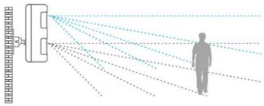
Note! If pet-immune function is applied, please do not adjust the angle up or down, but keep it parallel with the wall
Detection Scope

Installation Notices
Mount the detector to a location close to the entry or exit
The detector aims at preventing intrusion. Detecting human movement at the entry or exit is critical for security.
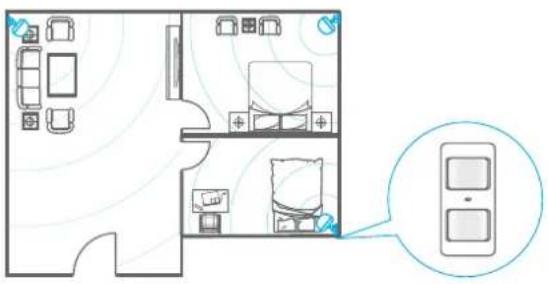
Mount the detector in a proper angle
The installation angle affects detection sensitivity. The sensitivity is optimal when the walk direction is vertical to the infrared direction. Choose the best location and angle according to the actual situation and detection scope diagram.

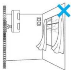
Don't face to glass windows or doors
Strong light interferes with detection sensitivity. In addition, complicated situations, such as traffic flow, stream of people, also should be avoided.
Don't face to or position close to heat sources
Heat and cold sources, such as heat extraction units, heaters, air conditioner, microwave oven, refrigerator, which may cause false alarm, should be avoided.
Don't face to swinging objects
Swinging objects may also trigger false alarm. Besides, if there are two detectors covering the save scope, adjust the locations to prevent cross-interference.


Specifications
Power Supply
DC 3V (AA 1.2V LR6 Battery x 2 pcs)
Static Current
≤ 90uA
Alarm Current
≤ 9.5mA
Detection Scope
8m/110"
Pet Immunity
≤ 25kg
Transmitting Distance
≤ 80m (in open area)
Radio Frequency
315MHz or 433.92MHz (± 75KHz)
Housing Material
ABS plastic
Operation Condition
Temperature: -10°C\~+55°C
Relative Humidity: ≤80% (non-condensing)
Detector Dimensions (L x W x H)
108×52×36.8mm
Bracket Dimensions (L × W × H)
52×30×26.5mm



- PSTN/KEYPAD SECURITY ALARM SYSTEM
- FEATURES
- SYSTEM SETTINGS 9\~15
- PHONE REMOTE CONTROL OPERATION 16
- ADD / DELETE WIRELESS ACCESSORIES 17
- ZONE SETUP OF WIRELESS ACCESSORIES 18
- SYSTEM SETTING LIST 19\~20
- FAQ 21
- SPECIFICATIONS 22
- WIRELESS REMOTE CONTROL 23\~25
- WIRELESS DOOR/WINDOW CONTACT 26\~29
- PET-IMMUNE PIR MOTION DETECTOR 30\~38
- INCLUDED ACCESSORIES
- CG-A9 CONTROL PANEL X 1
- PET-IMMNUE PIR MOTION DETECTOR X 1 BRACKET X 1
- WIRELESS DOOR/WINDOW CONTACT X 1
- WIRELESS REMOTE CONTROL X 2
- AC ADAPTER X 1
- TELEPHONE CABLE X 1
- CONTROL PANEL LAYOUT
- PREPARATION BEFORE USE
- POWER ON
- CONNECT PSTN LAND LINE
- INSTALLATION
- CONTROL PANEL OPERATION
- SYSTEM SETTINGS
- ENTER SETUP STATE
- NOTE
- SIREN RINGING TIME
- EXIT DELAY TIME
- ENTRY DELAY TIME
- SPECIAL TIPS
- SIREN VOLUME
- REMOTE PHONE CONTROL
- ENABLE PHONE REMOTE CONTROL
- DISABLE PHONE REMOTE CONTROL
- ARM/DISARM BEEP FOR WIRELESS SIREN
- LINECUT ALARM
- USER CODE
- ADMIN CODE
- RESET
- STORE ALARM PHONE NUMBER
- DELETE ALARM PHONE NUMBER
- USER ID
- UPLOADING ARM/ DISARM REPORT TO CMS CENTER
- PHONE REMOTE CONTROL OPERATION
- METHOD 1
- METHOD 2
- ADD/DELETE WIRELESS ACCESSORIES
- ADD WIRELESS ACCESSORIES
- DELETE WIRELESS ACCESSORIES
- ZONE SETUP OF WIRELESS ACCESSORIES
- SPECIFICATIONS
- PRODUCT NAME
- MODEL NO
- POWER SUPPLY
- STATIC CURRENCT
- ALARM CURRENCT
- BATTERY BACKUP
- INTERNAL SIREN VOLUME
- RADIO FREQUENCY
- ALLOWED AMOUNT OF EXPANDABLE WIRELESS ACCESSORIES
- HOUSING MATERIAL
- OPERATION CONDITION
- PANEL SIZE(LXWXH)
- WIRELESS REMOTE CONTROL
- DISARM
- HOME MODE (PART ARM)
- EMERGENCY CALL
- MUTE MODE
- WIRELESS DOOR/WINDOW CONTACT
- APPEARANCE
- LED INDICATION
- INSTALLATION & NOTICE
- PET-IMMUNE PIR MOTION DETECTOR
- WORKING MODE
- TESTING MODE
- POWER SAVING MODE
- TEST THE PIR MOTION DETECTOR
- ADJUST THE ANGLE
- DETECTION SCOPE
- INSTALLATION NOTICES
- MOUNT THE DETECTOR TO A LOCATION CLOSE TO THE ENTRY OR EXIT
- MOUNT THE DETECTOR IN A PROPER ANGLE
Marke : Chuango
Modell : CG-A9
Kategorie : Alarm