K2 - Heimtrainer BodyCraft - Kostenlose Bedienungsanleitung
Finden Sie kostenlos die Bedienungsanleitung des Geräts K2 BodyCraft als PDF.


Benutzerfragen zu K2 BodyCraft
0 Frage zu diesem Gerät. Beantworten Sie die, die Sie kennen, oder stellen Sie Ihre eigene.
Eine neue Frage zu diesem Gerät stellen
Laden Sie die Anleitung für Ihr Heimtrainer kostenlos im PDF-Format! Finden Sie Ihr Handbuch K2 - BodyCraft und nehmen Sie Ihr elektronisches Gerät wieder in die Hand. Auf dieser Seite sind alle Dokumente veröffentlicht, die für die Verwendung Ihres Geräts notwendig sind. K2 von der Marke BodyCraft.
BEDIENUNGSANLEITUNG K2 BodyCraft
Body Craft
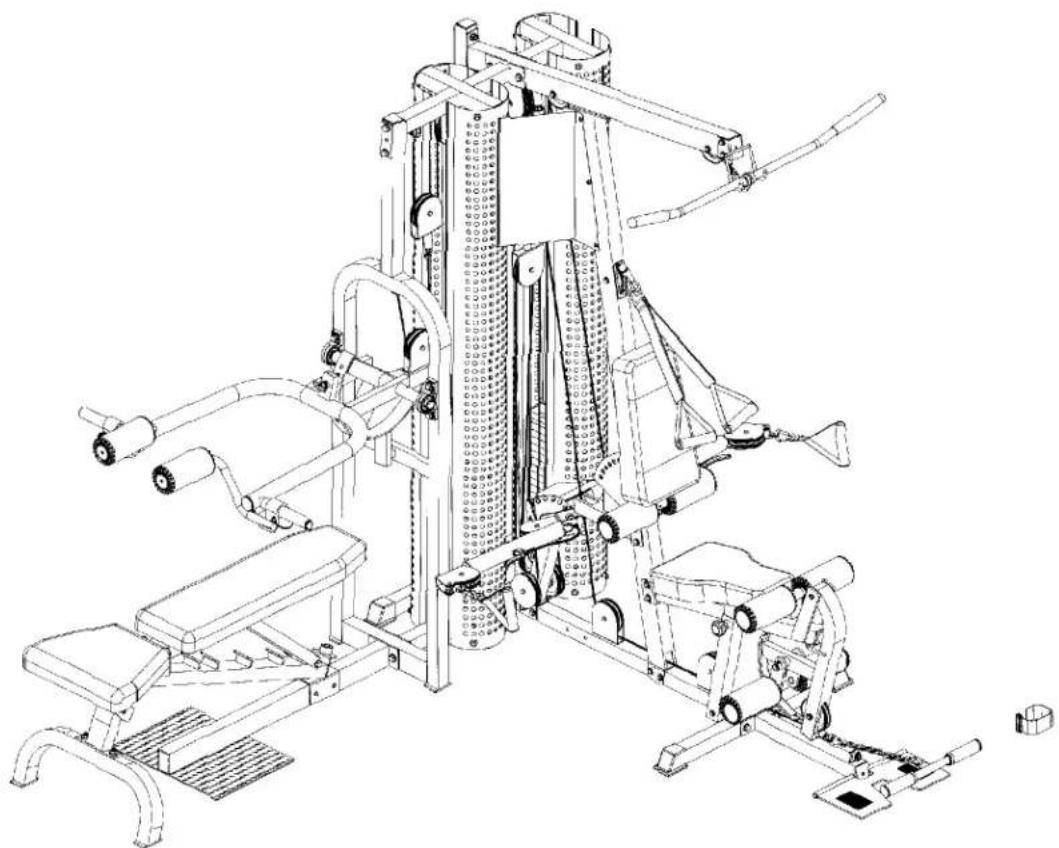
K2 GYM STRENGTH TRAINING SYSTEM INSTRUCTION MANUAL
natural_image
Technical line drawing of a gym machine with adjustable arms and legs (no text or symbols)QUESTION?
As a quality home gym supplier we are committed to your complete satisfaction. If you have questions, or find missing or damaged parts, we will guarantee your complete satisfaction through our authorized dealer service centers or our home office customer service department. Please call your local dealer for assistance or RSI at 800-990-5556 (9:00 AM - 5:00 PM). Our trained technicians will provide immediate assistance to you, free of charge.
We stand behind our products. Every piece, every part of this BODYCRAFT strength training system is guaranteed for as long as you own it. We will repair or replace anything that goes wrong.
Bodycraft is a division of Recreation Supply Inc.
P.O. BOX 181
Sunbury, OH 43074
BEFORE YOU BEGIN
Congratulations and thank you for selecting the K2 GYM strength training system. The K2 GYM offers an impressive array of strength training exercises to develop every major muscle group of the body. Whether your goal is cardiovascular fitness, a shapely, toned body or dramatic muscle size and strength, the K2 GYM will help you achieve the specific results you want. For your safety and benefit, read this manual and the accompanying literature before using the K2 GYM. Keep this manual for future reference.
If you have additional questions, please call your local dealer or our customer service department at 800-990-5556 Monday through Friday, 9 a.m. until 5 p.m. Eastern Time.
IMPORTANT SAFETY NOTES
There is a risk assumed by individuals who use this type of equipment. Before beginning this or any other exercise program consult your physician. This is especially important for individuals over the age of 35 or persons with pre-existing health problems. Recreation Supply, Inc. assumes no responsibility for personal injury or property damage sustained by or through use of this product.
- This product must be assembled on a flat, level surface to assure its proper function.
- Clean pads and frame on a regular basis. We recommend warm, soapy water. Do not use harsh or abrasive chemicals.
- Inspect and tighten all parts before every use. Replace any worn parts immediately. Failure to do so may result in serious injury.
- Keep children away from the K2 GYM at all times.
- Keep your hands away from cables and pulleys during operation. Keep your hands away from moving parts other than the designated handles.
- When adjusting the seat, make sure the spring pin is fully engaged. If not, the seat may slip and cause serious injury.
- Make certain all cables are seated within the pulleys before every use.
- Exercise with care to avoid injury.
- If unsure about the proper use of the K2 GYM strength training system call your local dealer or our customer service department at 800-990-5556.
other
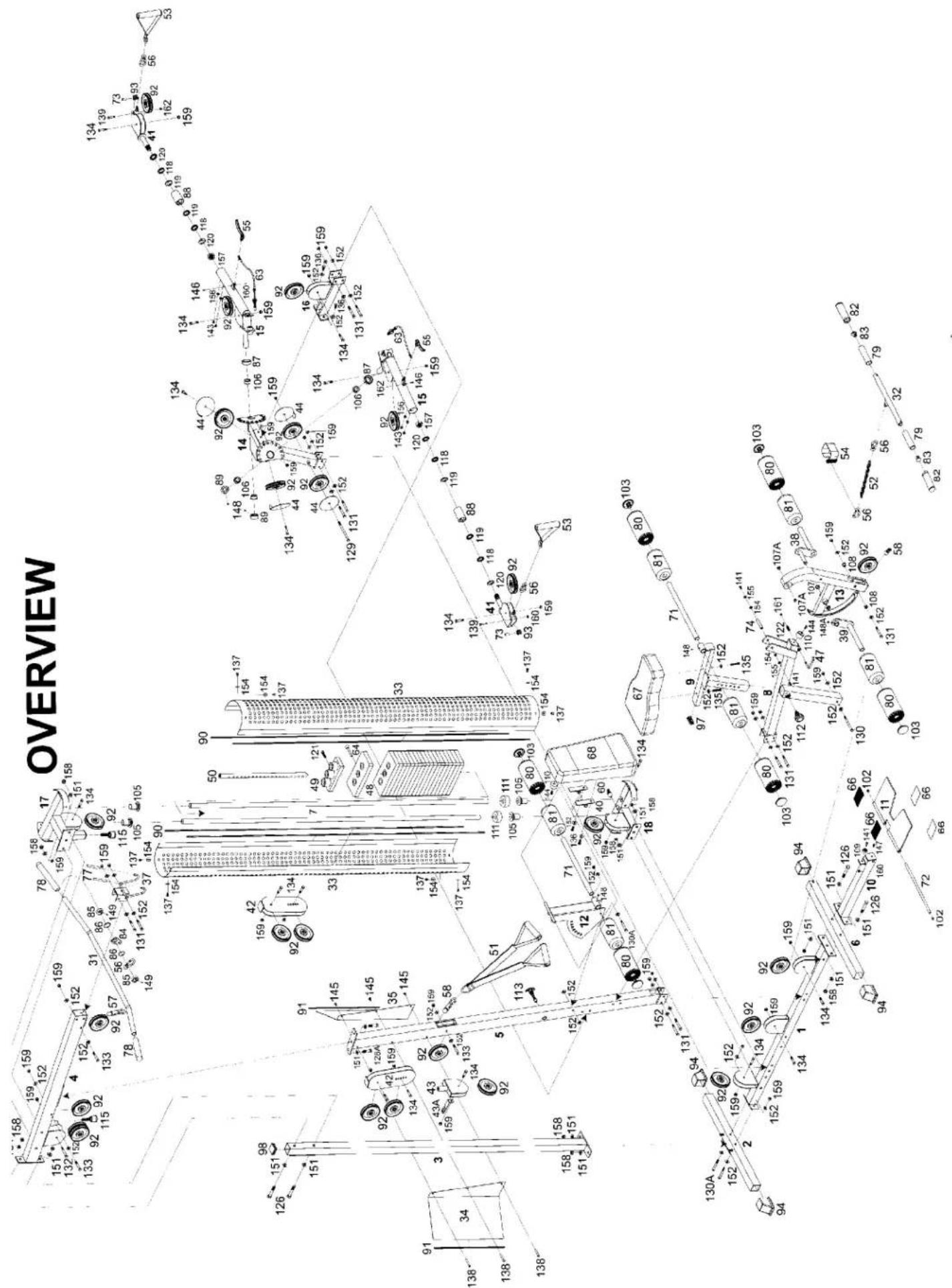
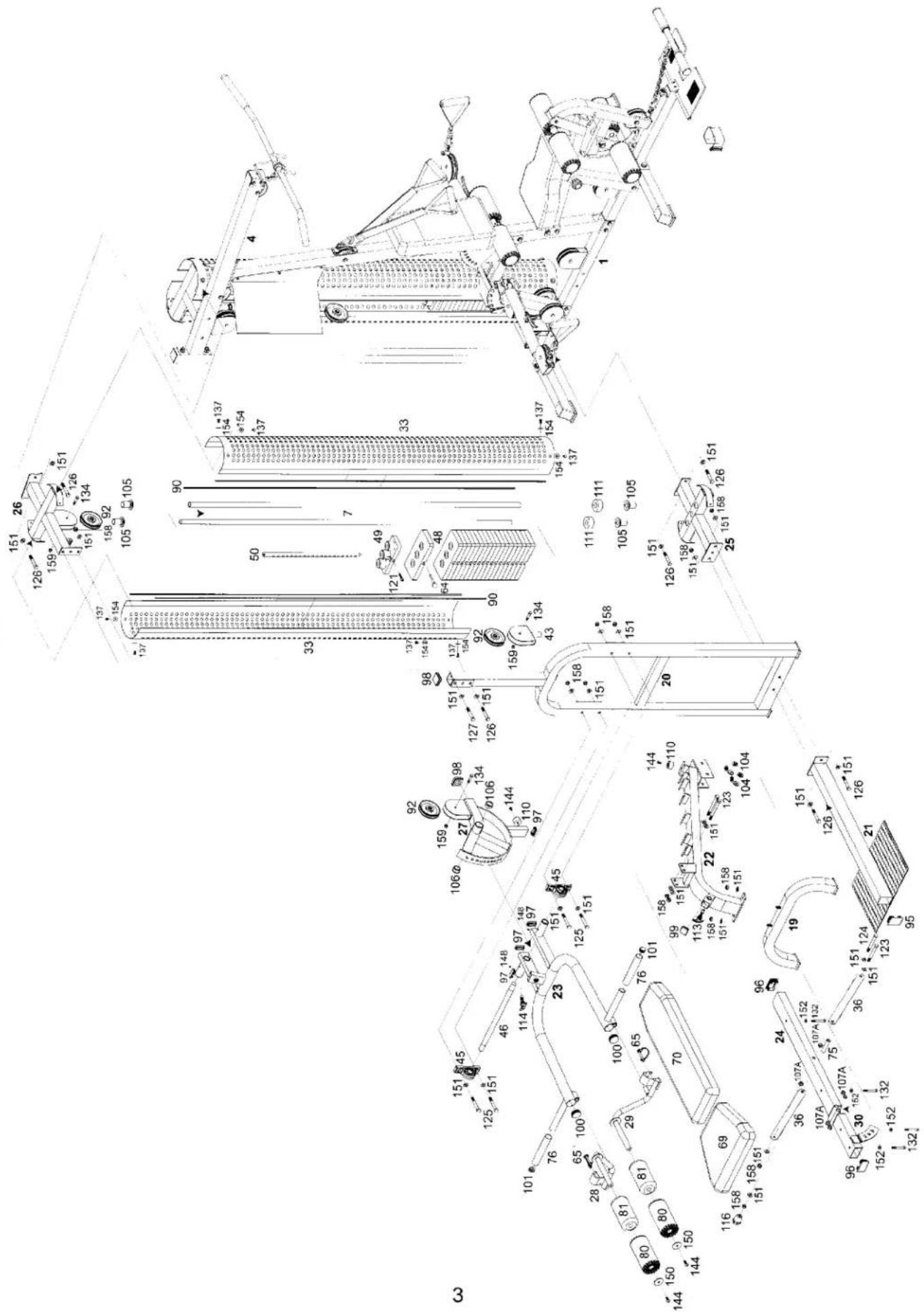
| Point ID | Position Label | |----------|----------------| | 1 | 158 | | 2 | 159 | | 3 | 158 | | 4 | 159 | | 5 | 158 | | 6 | 159 | | 7 | 159 | | 8 | 159 | | 9 | 159 | | 10 | 159 | | 11 | 159 | | 12 | 159 | | 13 | 159 | | 14 | 159 | | 15 | 159 | | 16 | 159 | | 17 | 159 | | 18 | 159 | | 19 | 159 | | 20 | 159 | | 21 | 159 | | 22 | 159 | | 23 | 159 | | 24 | 159 | | 25 | 159 | | 26 | 159 | | 27 | 159 | | 28 | 159 | | 29 | 159 | | 30 | 159 | | 31 | 159 | | 32 | 159 | | 33 | 159 | | 34 | 159 | | 35 | 159 | | 36 | 159 | | 37 | 159 | | 38 | 159 | | 39 | 159 | | 40 | 159 | | 41 | 159 | | 42 | 159 | | 43 | 159 | | 44 | 159 | | 45 | 159 | | 46 | 159 | | 47 | 159 | | 48 | 159 | | 49 | 159 | | 50 | 159 | | 51 | 159 | | 52 | 159 | | 53 | 159 | | 54 | 159 | | 55 | 159 | | 56 | 159 | | 57 | 159 | | 58 | 159 | | 59 | 159 | | 60 | 159 | | 61 | 159 | | 62 | 159 | | 63 | 159 | | 64 | 159 | | 65 | 159 | | 66 | 159 | | 67 | 159 | | 68 | 159 | | 69 | 159 | | 70 | 159 | | 71 | 159 | | 72 | 159 | | 73 | 159 | | 74 | 159 | | 75 | 159 | | 76 | 159 | | 77 | 159 | | 78 | 159 | | 79 | 159 | | 80 | 159 | | 81 | 159 | | 82 | 159 | | 83 | 159 | | 84 | 159 | | 85 | 159 | | 86 | 159 | | 87 | 159 | | 88 | 159 | | 89 | 159 | | 90 | 159 | | Note: The numbers in the 'Position' column are explicitly provided for each point of the diagram. The 'OVERVIEW' label appears at the top left corner.OVERVIEW
text_image
Technical schematic diagram of a mechanical assembly with numbered components and dimension annotationsPARTS LIST
NO. DESCRIPTION QTY.
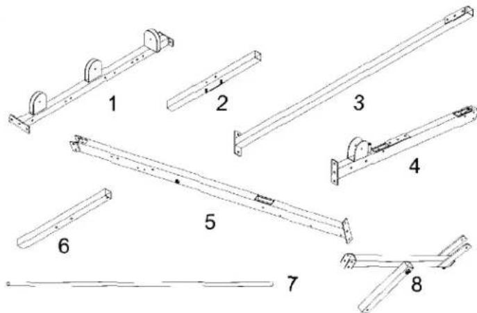
1 BASE FRAME
2 REAR STABILIZER
3 REAR UPRIGHT
4 TOP FRAME
5 FRONT UPRIGHT
6 FRONT STABILIZER
7 GUIDE ROD
8 SEAT FRAME
9 CHROMED SEAT ADJUSTER
10 FRONT EXTENDED FRAME
11 FOOT PLATE
12 BACK PAD ADJUSTER
13 LEG EXTENSION ARM
14 CABLE ARM ASSEMBLY
15 CABLE ARM
16 CABLE ARM CONNECTOR
17 GYM TOP GUIDE ROD RETAINER
18 GYM WEIGHT BASE
19 BENCH BASE FRAME
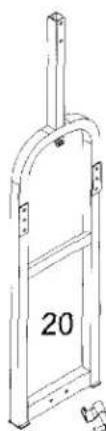
20 BENCH PRESS UPRIGHT
21 SQUAT FOOT PLATE
22 BENCH MAIN FRAME
23 BENCH PRESS ARM
24 BENCH BACK SUPPORT
25 BENCH PRESS WEIGHT BASE
26 BENCH TOP GUIDE ROD RETAINER
27 CHROMED PRESS ADJUSTER
28 LEFT SQUAT HANDLE
29 RIGHT SQUAT HANDLE
30 BENCH SEAT ADJUSTER
31 LAT BAR
32 LOW ROWER
33 SHROUD
34 RIGHT POSTER PLATE
35 LEFT POSTER PLATE
36 BACK PAD ADJUSTER
37 LAT BAR HOLDER
38 LEFT LEG EXTENSION ARM
39 RIGHT LEG EXTENSION ARM
40 METAL HINGE
41 SWIVEL CABLE TOP
42 FLOATING PULLEY BLOCK
43 SINGLE PULLEY BLOCK
43A CABLE GUIDE PLATE
44 PULLEY GUARD
45 PILLOW BLOCK BEARING
46 AXLE OF BENCH PRESS ARM
47 LEG EXTENSION LOCK PIN
48 WEIGHT PLATE
49 TOP PLATE
50 SELECTOR ROD
text_image
Technical diagram showing eight labeled mechanical or structural components with numbered parts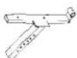
9
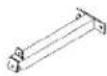
10
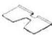
11

12
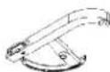
13
1
15

16

1

18

19
natural_image
Line drawing of a mechanical bracket or frame structure with no visible text or symbols[Non-Text]
21
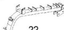
22
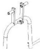
23
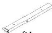
24
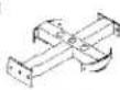
25
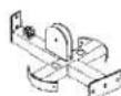
26
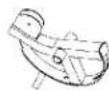
27

29
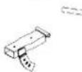
30
31
32

33
34
35

36

37

38

39

40

41

42

43

43A

44

45
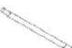
46

47

48

49
[Unreadable]

text_image
0 1/4 1/2 3/4 1" 1/4 1/2 3/4 2" 1/4 1/2 3/4 3" 1/4 1/2 3/4 4" 1/4 1/2 3/4 5" 1/4 1/2 3/4 6" (inch)PARTS LIST
NO. DESCRIPTION QTY.
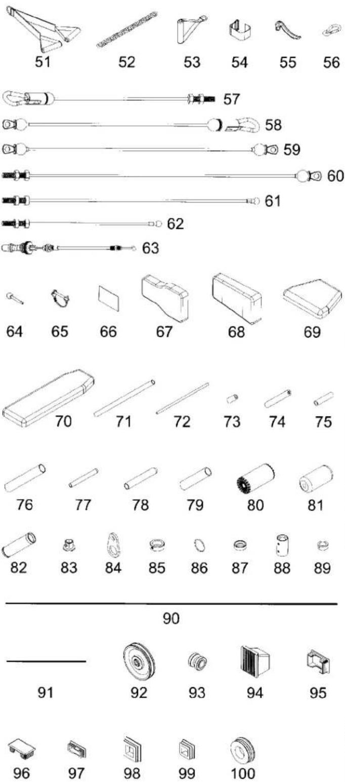
51 AB CRUNCH 1
52 LINK CHAIN 1
53 SINGLE HANDLE 2
54 ANKLE STRAP 1
55 CLUTCH LEVER OF CABLE ARM 2
56 SNAP HOOK 5
57 TOP CABLE 1
58 AB CABLE 1
59 CABLE ARM CABLE 1
60 CONNECTING CABLE 1
61 BENCH PRESS CABLE I 1
62 BENCH PRESS CABLE II 1
63 CLUTCH CABLE 2
64 SELECTOR PIN 2
65 SQUAT HANDLE BAR BRACKET 2
66 NON SLIP 4
67 SEAT PAD 1
68 BACK PAD 1
69 BENCH SEAT PAD 1
70 BENCH BACK PAD 1
71 FOAM ROLLER HOLDER 2
72 1/2" DIAMETER TUBE 1
73 SLEEVE 2
74 LEG EXTENSION AXLE 1
75 CONNECT SLEEVE 1
76 1-1/4" FOAM TUBE 2
77 8mm FOAM TUBE 2
78 1" HAND GRIP 2
79 1" PLASTIC SLEEVE 2
80 COVER OF FOAM PAD 8
81 FOAM PAD 8
82 1-1/4" HAND GRIP 2
83 1" T SHAPE END PLUG 2
84 HOOK PLATE 1
85 COLLAR 2
86 SEALING RING 2
87 STEEL SPACER 2
88 CABLE ARM COLLAR 2
89 CABLE ARM AXLE COLLAR 2
90 TRIM OF SHROUD 8
91 TRIM OF POSTER PLATE 2
92 PULLEY 28
93 SMALL PULLEY 2
94 50 SQ. END CAP 4
95 50mm X 75mm END PLUG 1
96 45mm X 75mm END PLUG 2
97 25mm X 50mm END PLUG 5
98 50mm SQ. PLUG 3
99 38mm SQ. PLUG 1
100 50mm ROUND PLUG 2

text_image
0 1/4 1/2 3/4 1" 1/4 1/2 3/4 2" 1/4 1/2 3/4 3" 1/4 1/2 3/4 4" 1/4 1/2 3/4 5" 1/4 1/2 3/4 6" (inch)PARTS LIST
NO. DESCRIPTION QTY.
| 101 | 1-1/4" PLUG | 2 |
| 102 | 1/2" ROUND PLUG | 2 |
| 103 | 1" ID FOAM ROLLER PLUG | 6 |
| 104 | SLIDE SPACER | 6 |
| 105 | PLASTIC GUIDE ROD HOLDER | 8 |
| 106 | 1" STEEL BUSHING | 6 |
| 107 | 3/4" STEEL BUSHING | 2 |
| 107A | 1/2" STEEL BUSHING | 8 |
| 108 | 3/8" BUSHING | 2 |
| 109 | 1/2" STOPPER | 1 |
| 110 | 1" STOPPER | 4 |
| 111 | RUBBER DONUT | 4 |
| 112 | SPRING KNOB | 1 |
| 113 | POP PIN (LONGER) | 2 |
| 114 | POP PIN (SHORTER) | 1 |
| 115 | ADJ. STOPPER | 2 |
| 116 | PLASTIC KNOB | 1 |
| 118 | BEARING | 4 |
| 119 | BEARING BASIN | 4 |
| 120 | BEARING COVER | 4 |
| 121 | TOP PLATE BOLT | 2 |
| 122 | SPRING | 1 |
| 123 | 1/2" X 5" HEX BOLT | 3 |
| 124 | 1/2" X 4-1/4" HEX BOLT | 1 |
| 125 | 1/2" X 3-1/2" HEX BOLT | 4 |
| 126 | 1/2" X 3-1/4" HEX BOLT | 11 |
| 127 | 1/2" X 3" HEX BOLT | 1 |
| 128A | 1/2" X 1" HEX BOLT | 2 |
| 129 | 3/8" X 5-3/4" HEX BOLT | 1 |
| 130 | 3/8" X 4-1/2" HEX BOLT | 1 |
| 130A | 3/8" x 3-1/8" HEX BOLT | 3 |
| 131 | 3/8" X 3" HEX BOLT | 11 |
| 132 | 3/8" X 2-3/4" HEX BOLT | 5 |
| 133 | 3/8" X 2-1/2" HEX BOLT | 3 |
| 134 | 3/8" X 1-3/4" HEX BOLT | 19 |
| 135 | 3/8" X 1-3/4" HEX BOLT (ALL) | 2 |
| 136 | 3/8" X 1" HEX BOLT (ALL) | 4 |
| 137 | 5/16" X 1/2" HEX BOLT (ALL) | 16 |
| 138 | FEMALE SCREW FOR POSTER | 3 |
| 139 | 5/16" X 1-1/2" HEX BOLT | 2 |
| 141 | 5/16" X 5/8" INNER HEX SCREW | 3 |
| 143 | 3/8" X 1/2" INNER HEX SCREW | 4 |
| 144 | 3/8" X 5/8" INNER HEX SCREW | 6 |
| 145 | 6mm X 12mm MALE NUT FOR POSTER | 3 |
| 146 | M5 X 18mm ROUND HEAD SCREW | 2 |
| 147 | 3/8" X 1/2" SET SCREW | 1 |
| 148 | 5/16" X 1/4" SET SCREW | 5 |
| 148A | 5/16" X 1/2" SET SCREW | 1 |
| 149 | M6 SET SCREW | 2 |
| 150 | 3/8" WASHER (LARGER) | 2 |
| 151 | 1/2" WASHER | 45 |
| 152 | 3/8" WASHER (SMALLER) | 48 |
| 154 | 5/16" WASHER | 18 |
| 155 | 5/16" SPRING WASHER | 2 |
| 156 | 3/8" SPRING WASHER | 4 |
| 157 | 24mm NYLON NUT | 2 |
| 158 | 1/2" NYLON NUT | 23 |
| 159 | 3/8" NYLON NUT | 40 |
| 160 | 5/16" NYLON NUT | 3 |
| 161 | M6 NYLON NUT | 1 |
| 162 | M5 NYLON NUT | 2 |
| 101 | 102 | 103 | 104 | 105 | 106 |
| 107 | 107A | 108 | 109 | 110 | |
| 111 | 112 | 113 | 114 | 115 | |
| 116 | 118 | 119 | 120 | 121 | 122 |
| 123 | 129 | 130 | 135 | 143 | |
| 124 | 130 | 136 | 137 | 144 | |
| 125 | 130A | 137 | 145 | ||
| 126 | 131 | 138 | 146 | ||
| 127 | 132 | 139 | 147 | ||
| 128A | 133 | 141 | 148 | ||
| 134 | 148A | ||||
| 149 | 150 | 151 | 152 | 154 | 155 |
| 157 | 158 | 159 | 160 | 161 | 162 |

text_image
0 1/4 1/2 3/4 1" 1/4 1/2 3/4 2" 1/4 1/2 3/4 3" 1/4 1/2 3/4 4" 1/4 1/2 3/4 5" 1/4 1/2 3/4 6" (inch)STEP 1 Main Frame Assembly
To ease the assembly process, do NOT tighten bolts until instructed.
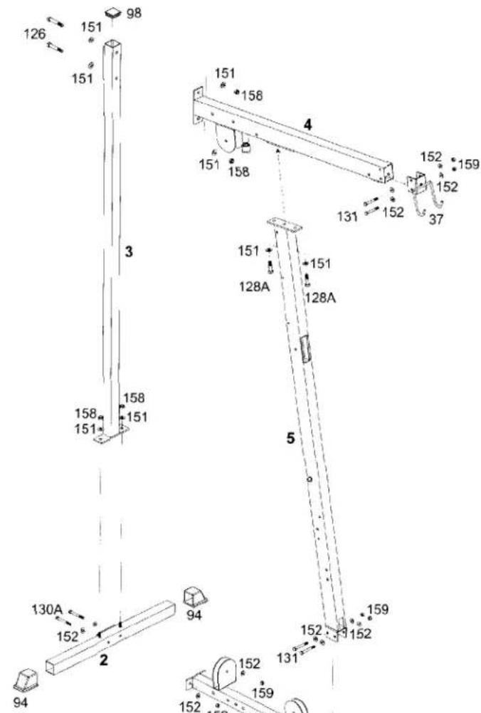
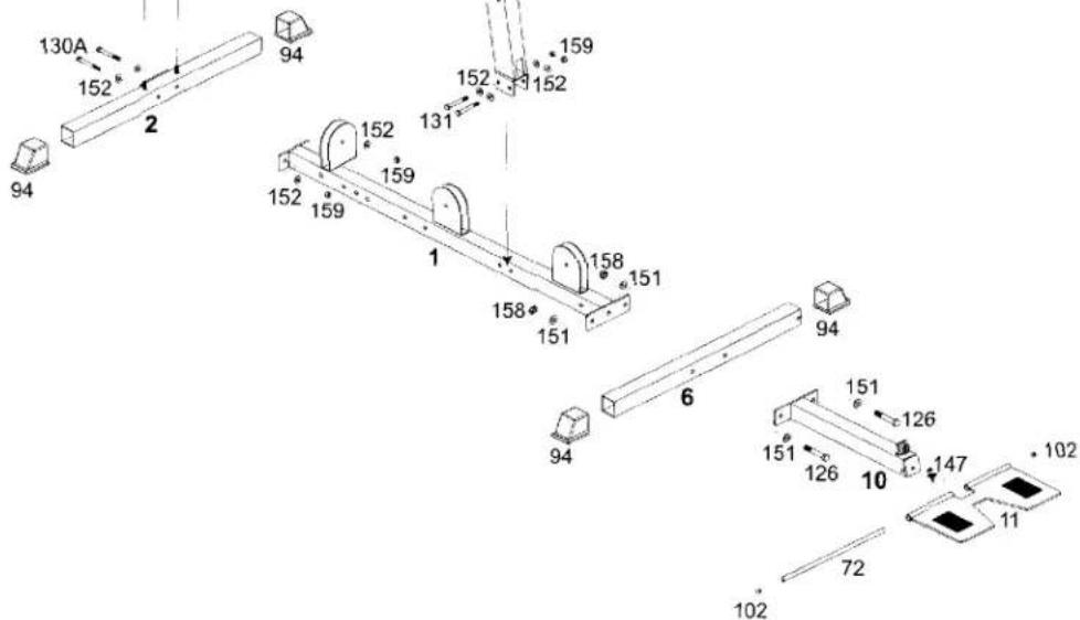
- Attach the Rear Stabilizer (2), to the Base Frame (1) using two 3/8" x 3-1/8" Hex Bolt (130A), four 3/8" Washers (152) and 3/8" Nylon Nuts (159). Attach Front Extended Frame (10) and Front Stabilizer (6) to the Base Frame (1) using two 1/2" X 3-1/4" Hex Bolts (126), four 1/2" Washers (151) and two 1/2" Nylon Nuts (158). Cap the Rear and Front Stabilizers (2&6) with four 50mm SQ End Caps (94).
- Attach the Rear Upright (3) to the bolts on the Rear Stabilizer (2), using two 1/2" Washers (151), and two 1/2" Nylon Nuts (158). Cap the top of the Rear Upright (3) with a 50mm SQ Plug (98).
text_image
126 151 98 151 151 158 4 151 158 152 159 151 158 131 152 37 158 158 151 128A 128A 5 130A 152 2 94 94 152 152 159 131 152 159- Attach the Front Upright (5) to the Base Frame (1), using two 3/8" X 3" Hex Bolts (131), four 3/8" Washers (152) and two 3/8" Nuts (159).
- Attach the Top Frame (4) to the Rear Upright (3), using two 1/2" X 3-1/4" Hex Bolts (126), four 1/2" Washers (151) and two 1/2" Nuts (158). Attach the Front Upright (5) to the threaded holes in Top Frame (4) using two 1/2" X 1" Hex Bolts (128A) and two 1/2" Washers (151).
- Attach the Lat Bar Holder (37) to the Top Frame (4), using two 3/8" X 3" Hex Bolts (131), four 3/8" Washers (152) and two 3/8" Nuts (159).
- Attach the Foot Plate (11) to the Front Extended Frame (10) by aligning the holes and inserting the 1/2" Diameter Tube (72). Cap the 1/2" Diameter Tube (72) with two 1/2" Round Plugs (102). Secure the 1/2" Diameter Tube (72) by tightening the pre-installed 3/8" X 1/2" Set Screw (147).
text_image
130A 152 94 152 159 131 152 152 152 159 158 151 158 151 6 94 94 151 126 151 126 10 147 102 11 72 102STEP 2 Weight Stack Assembly
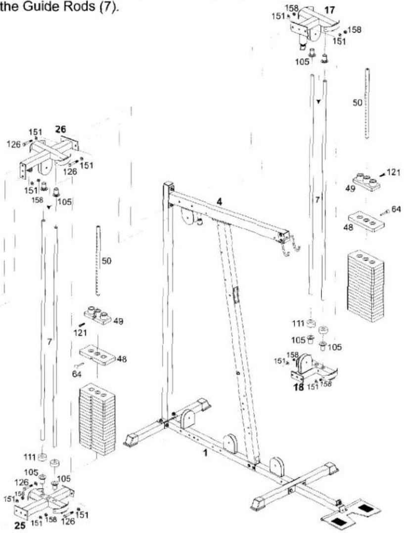
- Attach the Gym Weight Base (18) and the Bench Press Weight Base (25) to the Base Frame (1) using two 1/2" X 3-1/4" Hex Bolts (126), four 1/2" Washers (151) and two 1/2" Nuts (158). Insert four plastic Guide Rod Holders (105) into the holes in each Weight Base (18 & 25). Also insert four plastic Guide Rod Holders (105) into the holes in each Top Guide Rod Retainer (17 & 26) as shown. Slide a Rubber Donut (111) onto one end of each Guide Rod (7). Insert the Guide Rods (7) into the Plastic Guide Rod Holders (105) in each Weight Base (18&25) as shown.
- Attach the Squat Foot Plate (21) and the Bench Press Upright (20) to the Bench Press Weight Base (25) using two 1/2" X 3-1/4" Hex Bolts (126), four 1/2" Washers (151) and two 1/2" Nuts (158). Cap the Squat Foot Plate (21) with one 50mm X 75mm Plug (95) and the Bench Press Upright (20) with one 50 mm SQ Plug (98).
- Slide each Weight Plate (48) over the Guide Rods (7). Make certain that each plate is oriented with the selector hole on the bottom and facing forward. Attach the Top Plate (49) to the Selector Rod (50) using the Top Plate Bolt (121). Tighten the Top Plate Bolt (121). Slide the Top Plate (49) and Selector Rod (50) onto the Guide Rods (7).
- Slide Gym Top Guide Rod Retainer and Bench Top Guide Rod Retainer (17 & 26) over top of the Guide Rods (7) and attach both Top Guide Rod Retainers to the Top Frame (4), using two 1/2" X 3-1/4" Hex Bolts (126), four 1/2" Washers (151) and two 1/2" Nuts (158).
- Attach the Bench Press Upright (20) to the Bench Top Guide Rod Retainer (26), using one 1/2" X 3" Hex Bolt (127) (into pre-threaded hole) and one 1/2" X 3-1/4" Hex Bolt (126), three 1/2" Washers (151) and one 1/2" Nut (158) (through bottom hole).
text_image
the Guide Rods (7). 158 151 158 151 105 50 26 126 126 151 151 158 105 49 121 48 64 7 50 49 121 48 64 111 105 105 158 151 158 18 151 158 1 111 105 105 158 151 158 25 105 126 105 151 158 126 1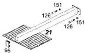
text_image
151 126 126 151 21 95STEP 3 Cable Arm Assembly
-
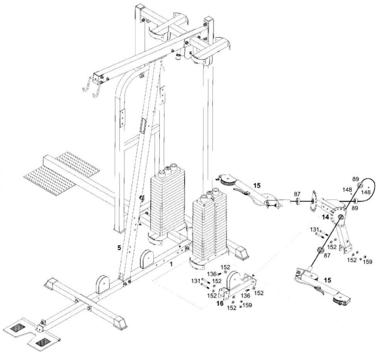
Attach the Cable Arm Connector (16) to the Front Upright (5) using two 3/8" X 3" Hex Bolts (131), four 3/8" Washers (152) and two 3/8" Nuts (159). Attach the Cable Arm Connector (16) to the pre-threaded holes in the Cable Arm Assembly (14), using two 3/8" X 1" Hex Bolts (136) and two 3/8" Washers (152). Remember to keep all bolts loose to ensure holes will align easily. Attach the Cable Arm Assembly (14) to the Base Frame (1) using two 3/8" X 3" Hex Bolts (131), four 3/8" Washers (152) and two 3/8" Nuts (159).
-
Slide the axle of each Cable Arm (15) through the holes in the selector plates in the Cable Arm Assembly (14) and fasten using the Axle Collars (89) and tightening by each 5/16" X 1/4" Set Screw (148). Check to ensure that each Cable Arm pivots freely and any cables are not twisted.
text_image
Technical diagram of a mechanical lifting device with numbered components and motion indicatorsSTEP 4 Bench Press Arm Assembly
We recommend two people for completion of this step.
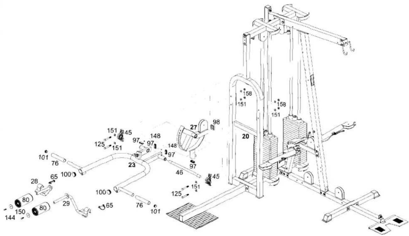
- Attach the Chromed Press Adjuster (27) to the Bench Press Arm (23) by inserting the Axle of Bench Press Arm (46). Slide a Pillow Block Bearing (45) onto each end of the Axle of Bench Press Arm (46).
- Attach the two Pillow Block Bearings (45) to the Bench Press Upright (20) using two 1/2" X 3-1/2" Hex Bolts (125), four 1/2" Washers (151) and two 1/2" Nuts (158). Plug the back side of the Press Arm (23) with two 25mm X 50mm Plugs (97) and plug the front side of the Bench Press Arm (23) with two 50 mm Round Plugs (100).
- Moisten the center of two Foam Pads (80) with water and then slide onto the Left and Right Squat Handle Bars (28 & 29). Secure the pads with a (larger) 3/8" Washer (150) and a 3/8" X 5/8" Inner Hex Screw (144).
text_image
Technical diagram of a gym equipment with numbered components and labeled partsSTEP 5 Seat And Back Assembly
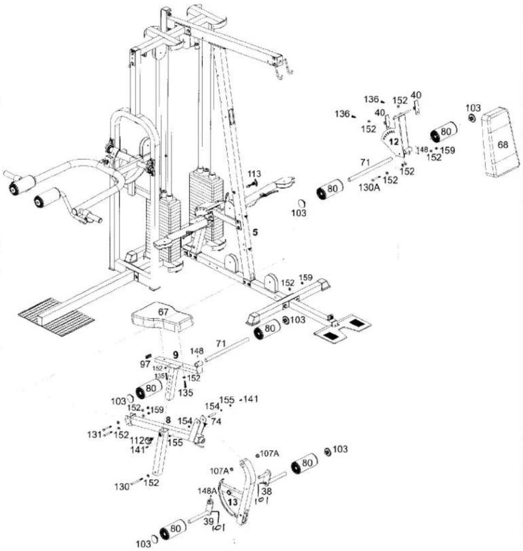
- Attach the Seat Frame (8) to the Front Upright (5), using two 3/8" X 3" Hex Bolts (131), four 3/8" Washers (152) and two 3/8" Nuts (159). Attach the Seat Frame (8) to the Base Frame (1) using one 3/8" X 4-1/2" Hex Bolt (130), two 3/8" Washers (152) and one 3/8" Nut (159).
- Attach the Leg Extension Arm (13) to the Seat Frame (8) by aligning holes and then inserting the Leg Extension Axle (74). Fasten the Leg Extension Axle (74) using two 5/16" Washers (154), two 5/16" Spring Washers (155) and two 5/16" X 5/8" Inner Hex Screw (141).
- Insert two 3/4" Steel Bushings (107) into the holes in the Leg Extension Arm (13). Attach the Left and Right Leg Extension Arms (38 & 39) to the Leg Extension Arm (13) by tightening the 5/16" X 1/2" Set Screw (148A). Moisten the center of two Foam Pads (80) and slide onto each end of the Left and Right Leg Extension Arms (38&39). Secure the pads with a 1" ID Foam Roller Plug (103).
- Attach the Seat Pad (67) to the Chromed Seat Adjuster (9), using two 3/8" X 1-3/4" Hex Bolts (135) and two 3/8" Washers (152). Then insert the Chromed Seat Adjuster (9) into the Seat Frame (8). Pull the Spring Knob (112) out to adjust the Chromed Seat Adjuster (9) to your desired height.
- Insert a Foam Roller Holder (71) into the tube on the front of the Chromed Seat Adjuster (9). Moisten the center of two Foam Pads (80) with water and slide onto each end of the Foam Roller Holder (71). Secure the pads with a 1" ID Foam Roller Plug (103). Secure the Foam Roller Holder (71) by tightening the pre-installed 5/16" X 1/4" Set Screw (148).
-
Attach the Back Pad Adjuster (12) to the Front Upright (5), using one 3/8" X 3-1/8" Hex Bolt (130A), two 3/8" Washers (152) and one 3/8" Nut (159). It may be necessary tighten this bolt, then loosen just to let Back Pad Adjuster (12) pivot freely. Insert Pop Pin (113) to Front Upright (5) to hold Back Pad Adjuster (12) in place.
-
Slide Metal Hinge (40) to top of Back Pad Adjuster (12), then attach Back Pad (68) to Metal Hinge (40), using two 3/8" X 1" Hex Bolts (136) and 3/8" Washers (152). Inserting Foam Roller Holder (71) through the bottom hole of Back Pad Adjuster (12). Moisten the center of Foam Pads (80) with water and slide onto each end of Foam Roller Holder (71). Secure the pads with a 1" ID Foam Roller Plug (103). Secure the Foam Roller Holder (71) by tightening the pre-installed 5/16" X 1/4" Set Screw (148).
text_image
Technical diagram of a gym machine with numbered components and labeled partsSTEP 6 Bench Assembly
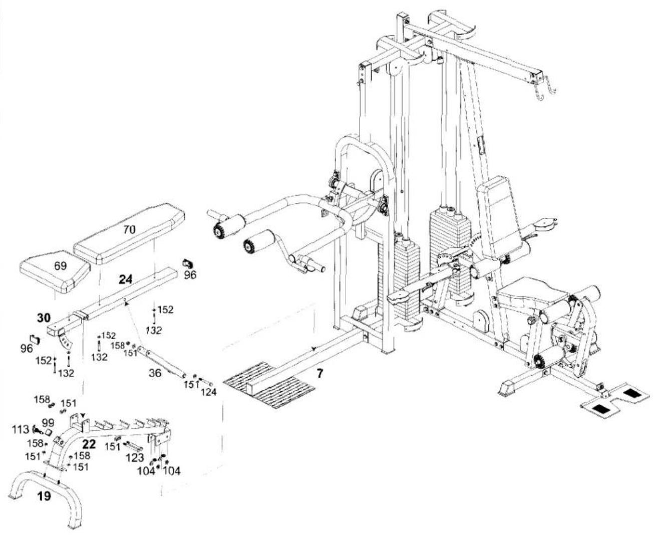
- Attach the Bench Main Frame (22) to Bench Base frame (19), using two 1/2" Washers (151) and two 1/2" Nuts (158).
- Attach the Bench Back Support (24) and Bench Seat Adjuster (30) to the Bench Main Frame (22), using two 1/2" X 5" Hex Bolts (123), four 1/2" Washers (151) and two 1/2" Nuts (158). Tighten these bolts and then loosen just enough for the Seat and Back to pivot freely. Attach the Bench Seat Pad (69) to Bench Seat Adjuster (30) using two 3/8" X 2-3/4" Hex Bolts (132) and 3/8" Washers (152). Attach the Bench Back Pad (70) to the Bench Back Support (24) using two 3/8" X 2-3/4" Hex Bolts (132) and 3/8" Washers (152).
- Attach the Back Pad Adjusters (36) to the Back Support (24), using one 1/2" X 4-1/4" Hex Bolt (124), two 1/2" Washers (151) and one 1/2" Nut (158). Tighten this bolt and then loosen just enough for the Back Pad Adjusters (12) to swing freely. Insert a 45mm X 75mm Plug (96) into the Bench Back Support (24) and a 45mm X 75mm Plug (96) into the Bench Seat Arm (30).
text_image
Technical diagram of a gym machine with numbered components and labeled partsSTEP 7 Top Cable
ball with hook end
TOP CABLE (57)
bolt end
Assemble cables and pulleys simultaneously.
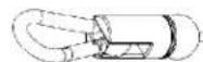
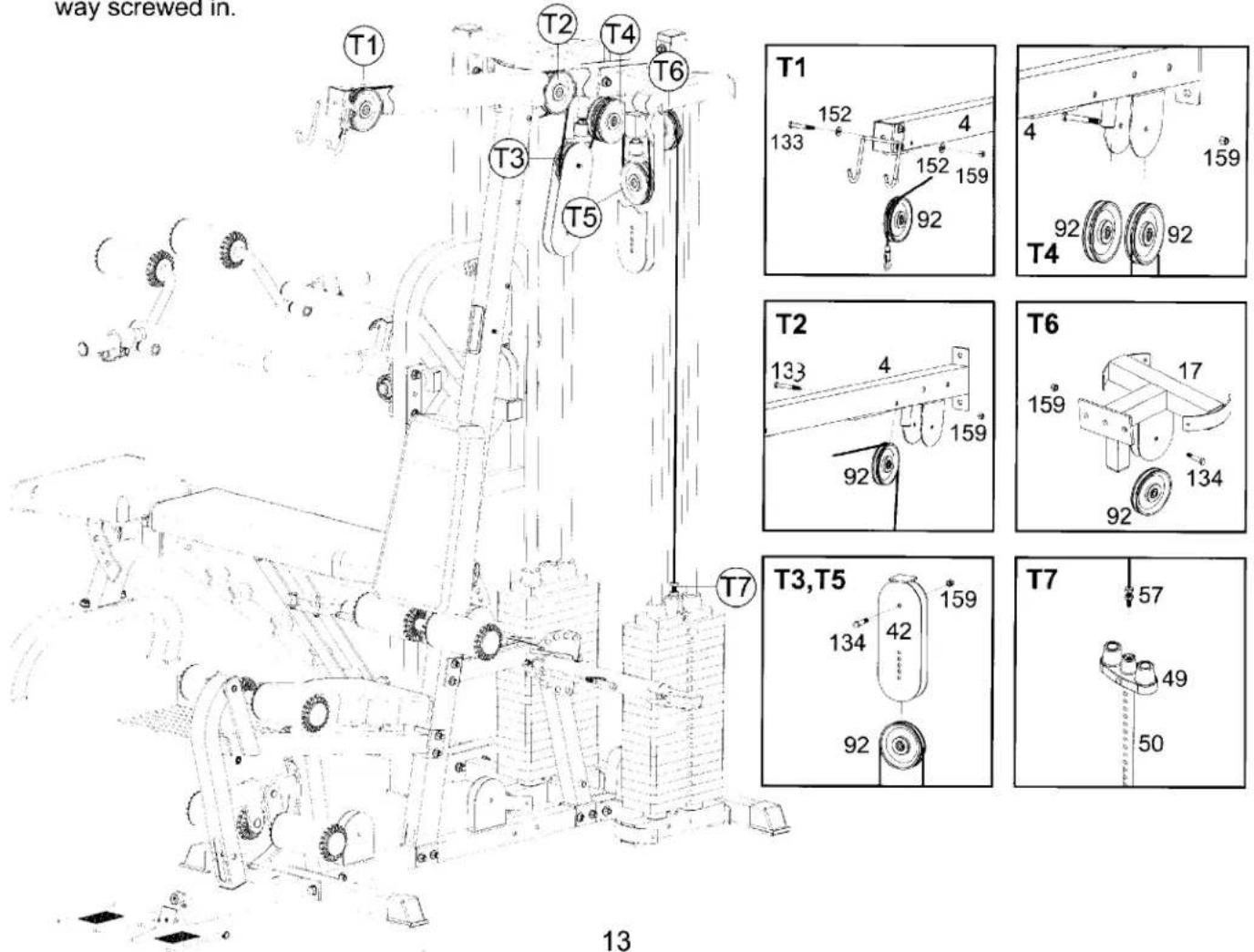
- Insert the threaded end of the Top Cable (57) into the slot in the front of the Top Frame (4) as shown in inset T1, and insert a pulley into the slot using one 3/8" X 2-1/2" Hex Bolt (133), two 3/8" Washers (152) and one 3/8" Nut (159). Route the cable over this pulley, through the Top Frame (4) and over the pulley mounted (using one 3/8" X 2-1/2" Hex Bolt (133), two 3/8" Washers (152) and one 3/8" Nut (159) in the rear of the Top Frame as shown in inset T2.
- Mount a pulley in the top hole of one Floating Pulley Block (42) using one 3/8" X 1-3/4" Hex Bolt (134) and one 3/8" Nut (159). Continue cable routing down and around the top pulley in the Floating Pulley Block (42) as shown in inset T3, T5.
- Continue cable routing up and over the left side (as if sitting on seat) pulley mounted on Top Frame (4) as shown in inset T4. Use one 3/8" X 2-3/4" Hex Bolt (132) and one 3/8" Nut (159) to mount the pulley.
- Mount a pulley in the top hole of the other Floating Pulley Block (42) using one 3/8" X 1-3/4" Hex Bolt (134) and one 3/8" Nut (159). Continue cable routing down and around the top pulley in the Floating Pulley Block (42) as shown in inset T3, T5.
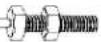
- Continue cable routing up and over the pulley mounted on the Top Guide Rod Retainer as shown in T6. Mount the pulley using one 3/8" X 1-3/4" Hex Bolt (134) and one 3/8" Nut (159). Screw the threaded end of the Top Cable (57) into the Top Plate (49). The bolt should be at least one-third of the way screwed in.
text_image
way screwed in. T1 T2 T4 T6 T3 T5 T1 133 152 4 152 159 92 T4 159 92 T2 133 4 159 92 T6 159 17 134 92 T3,T5 134 42 159 92 T7 57 49 50 13STEP 8 AB Cable

text_image
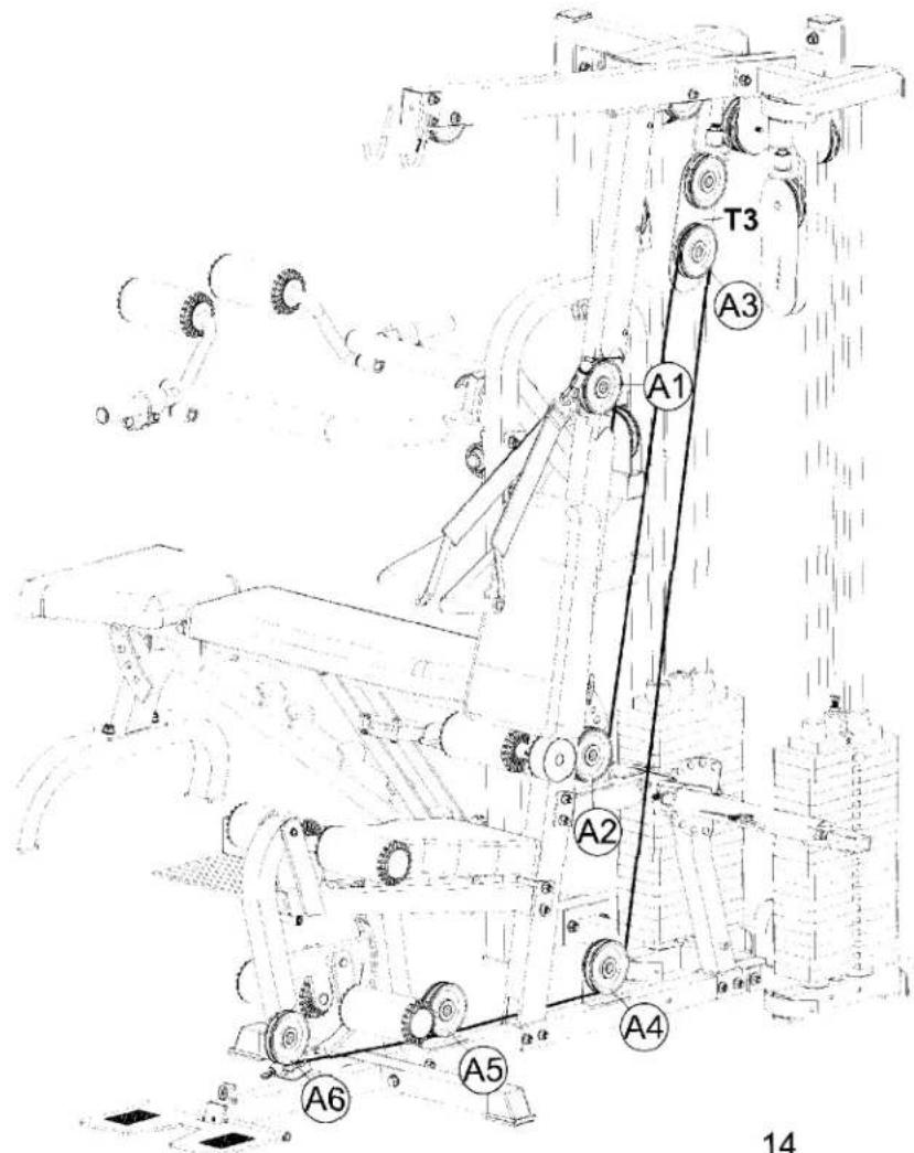
ball end AB CABLE (58) ball with hook end- Route the AB cable (58) through the slot and over the pulley mounted in Front Upright (5) as shown in inset A1. Mount pulley using one 3/8" X 2-1/2" Hex Bolt (133), two 3/8" Washers (152) and one 3/8" Nut (159).
- Continue cable routing down to the pulley mounted on Cable Arm Connector (16) as shown in inset A2. Mount the pulley using one 3/8" X 1-3/4" Hex Bolt (134) and one 3/8" Nut (159).
- Continue cable routing up and over the pulley mounted in lower half of the Floating Pulley Block (42) as shown in inset A3. Mount the pulley in one of the bottom holes of the Floating Pulley Block (42) using one 3/8" X 1-3/4" Hex Bolt (134) and one 3/8" Nut (159). The multiple holes are for cable adjustment. When cabling is complete, this pulley can be moved upward to take up slack, or downward to gain length.
- Continue cable routing down to the pulley mounted on Base Frame (1) as shown in inset A4. Mount the pulley using one 3/8" X 1-3/4" Hex Bolt (134) and one 3/8" Nut (159).
- Continue cable forward, toward the front of the machine, under pulley A5. Mount the pulley using one 3/8" X 1-3/4" Hex Bolt (134) and one 3/8" Nut (159).
- End the routing of the AB cable (58) under the pulley on the Leg Extension Arm (13). Mount the pulley using one 3/8" X 3" Hex Bolt (131), two 3/8" Washers (152), two 3/8" Bushings (108) and one 3/8" Nut (159) as shown in inset A6.
text_image
T3 A3 A1 A2 A4 A5 A6 14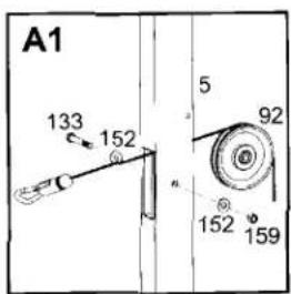
text_image
A1 133 152 5 92 152 159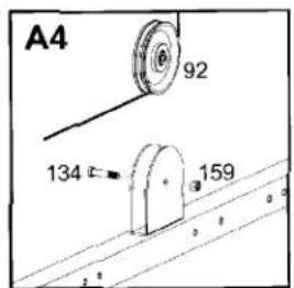
text_image
A4 92 134 159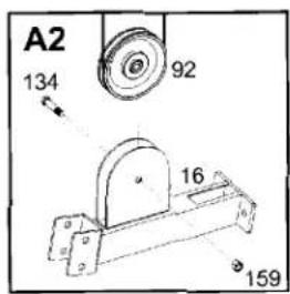
text_image
A2 134 92 16 159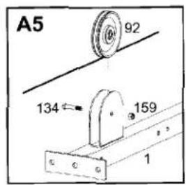
text_image
A5 92 134 159 1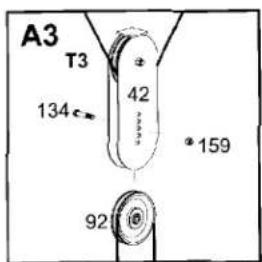
text_image
A3 T3 134 42 92 *159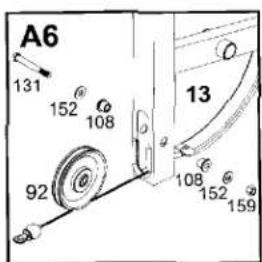
text_image
A6 131 152 108 92 13 108 152 159STEP 9 Connecting Cable

text_image
bolt end CONNECTING CABLE (60) ball end"Please do not use this Connecting Cable if you own the optional leg press. Use the Leg Press Cable found in the Leg Press box."
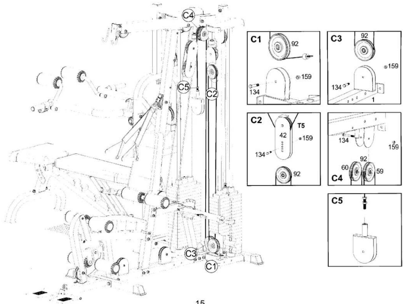
- Route the Connecting Cable (60) under the pulley mounted on the Base Frame (1) just behind the weight stack. Mount the pulley using one 3/8" X 1-3/4" Hex Bolt (134) and one 3/8" Nut (159) as shown in inset C1 with the ball end of the cable toward the weight stack.
- Continue cable routing up and over the pulley mounted in lower half of the Floating Pulley Block (42) as shown in inset C2. Mount the pulley in one of the bottom holes of the Floating Pulley Block (42) using one 3/8" X 1-3/4" Hex Bolt (134) and one 3/8" Nut (159). The multiple holes are for cable adjustment. When cabling is complete, this pulley can be moved upward to take up slack, or downward to gain length.
- Continue cable routing down to the pulley on the Base Frame (1) as shown in inset C3. Mount the pulley using one 3/8" X 1-3/4" Hex Bolt (134) and one 3/8" Nut (159).
- Continue cable routing up to the right side pulley in the Top Frame (4) as shown in inset C4, then down to the threaded receptor on the Single Pulley Block (43) as shown in inset C5. The bolt should be at least one-third of the way screwed in.
text_image
C4 C5 C2 C1 92 159 134 C3 92 159 134 1 C2 T5 42 159 134 92 159 60 92 59 C4 C5 C3 C1 15STEP 10 Cable Arm Cable

text_image
ball end CABLE ARM CABLE (59) ball endAttach pulleys and Pulley Guards (44) to the Cable Arm Assembly (14) as shown in insets K3, K4, and K6. Be certain that, when tightened, the Pulley Guards do not interfere with the cable movement. Route the Cable Arm Cable (59) around these pulleys as shown and around the pulley in the Single Pulley Block (43).
Mount a pulley into the Single Pulley Block (43) and attach the Cable Guide Plate (43A) (facing upward) to the Single Pulley Block (43) using one 3/8" X 1-3/4" Hex Bolt (134) and one 3/8" Nut as shown in inset K5. Insert the rear side of the Connecting Cable into the slot of the Cable Guide Plate (43A). This cable guide is included to ensure that the Cable Arms Cable does not twist.

text_image
K1,K9 120 119 119 120 157 118 88 118 41 143 134 139 92 73 93 159 162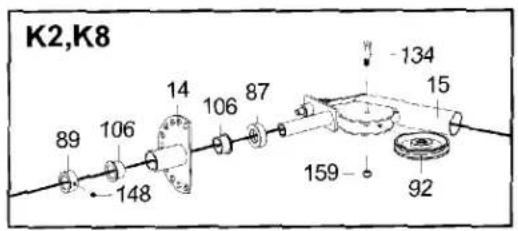
text_image
K2,K8 89 106 14 106 87 134 148 159 92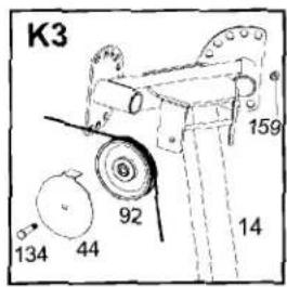
text_image
K3 159 92 14 134 44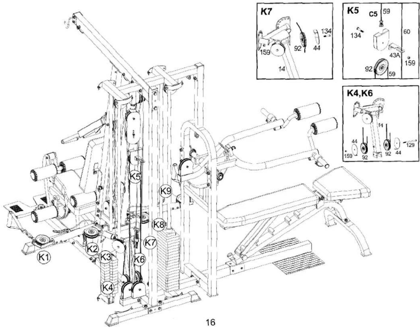
text_image
K1 K2 K3 K4 K5 K6 K7 K8 K9 14 159 92 44 134 159 134 59 60 43A 92 59 159 159 129 14 159 129 14 159 129STEP 11 Bench Press Cable I

text_image
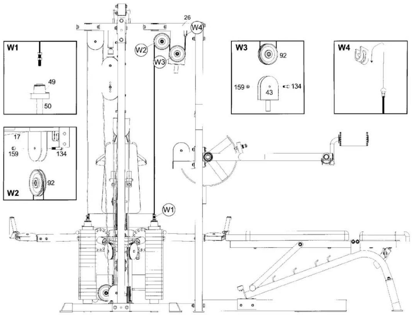
bolt end BENCH PRESS CABLE I (61) metal ball end- Insert the threaded end of the Bench Press cable (62) into the Top Plate (49) as shown in inset W1. Route the cable up and over the pulley mounted on the Bench Top Guide Rod Retainer (26). Mount the pulley using one 3/8" X 1-3/4" Bolt (134) and one 3/8" Nut (159).
- Continue cable routing down to the pulley in the Single Pulley Block (43) as show in inset W3. Mount the pulley using one 3/8" X 1-3/4" Hex Bolt (134) and one 3/8" Nut (159).
- Hook the metal ball end into the bracket welded on the Bench Top Guide Rod Retainer (26).
text_image
W1 49 50 W2 17 159 134 W2 92 W1 W2 W3 W3 26 W4 W3 92 159 43 134 W4STEP 12 Bench Press Cable II

text_image
bolt end BENCH PRESS CABLE II (62) metal ball end- Screw the threaded end of the Bench Press Cable II into the Single Pulley Block (43) (at least one-third of the threads) as shown in inset S1, then route down and under the pulley mounted on the Adj. Press Cam (27) as shown in inset S2. Mount the pulley using one 3/8" X 1-3/4" Hex Bolt (134) and one 3/8" Nut (159).
- Continue routing the cable up to the receptor on the bracket welded on the Bench Press Upright (20) as shown in inset S3.
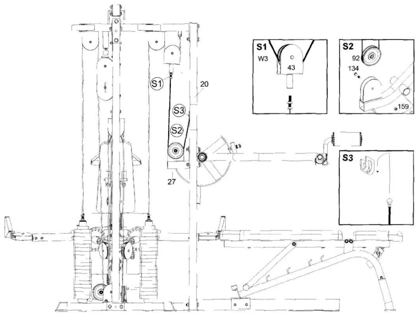
text_image
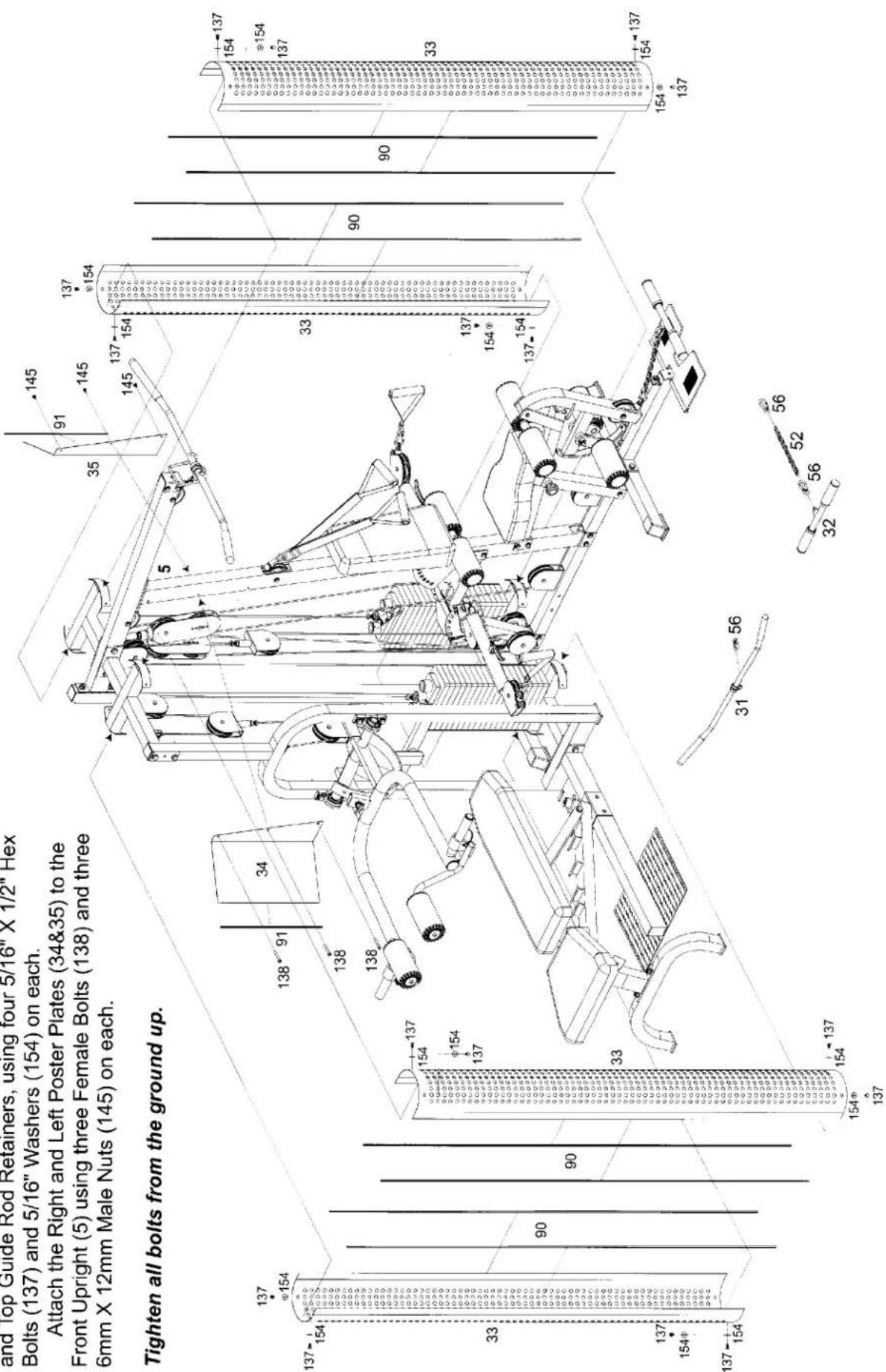
S1 20 S3 S2 27 S1 W3 43 S2 92 134 159 S3STEP 13 Shroud and Poster Plate Assembly
Attach the four Shrouds (33) to the Weight Base Frames
and Top Guide Rod Retainers, using four 5/16" X 1/2" Hex
Bolts (137) and 5/16" Washers (154) on each.
Attach the Right and Left Poster Plates (34&35) to the
Front Upright (5) using three Female Bolts (138) and three 6mm X 12mm Male Nuts (145) on each.
Tighten all bolts from the ground up.
text_image
and Top Guide Rod Retainers, using four 5/16" X 1/2" Hex Bolts (137) and 5/16" Washers (154) on each. Attach the Right and Left Poster Plates (34&35) to the Front Upright (5) using three Female Bolts (138) and three 6mm X 12mm Male Nuts (145) on each. Tighten all bolts from the ground up.Assembly is complete! Please take the following steps before using the gym:
Make certain all bolts are tightened securely.
2Make certain all cables are seated into all pulley grooves. A cable rubbing against steel will peel the nylon coating, voiding warranty and resulting in a need for replacement.
3Pre-stretch the cables. Put the Weight Selector Pin (64) in the bottom hole on the weight stack. Pull on the cables with great force, helping remove any kinks and providing any initial cable stretch.
4Be aware the cables can loosen and slightly stretch upon initial use.
5The cables should be adjusted as tight as possible, but no so tight as to lift the Top Plate (49) above the weight stack. Be certain to secure the jam nuts after adjustments are made.
6For better performance, apply a household lubricant (such as silicone) to any adjustable areas and to the Guide Rods (7).
7Enjoy many years of a Fit Lifestyle.
Thank you for purchasing the K2 GYM. If You have any questions, please call your local BodyCraft dealer or call our customer service department at 800-990-5556