Omnisat B2554 - Satellitenempfänger Maxview - Kostenlose Bedienungsanleitung
Finden Sie kostenlos die Bedienungsanleitung des Geräts Omnisat B2554 Maxview als PDF.


| Produkttyp | Tragbares Satellitenset |
| Modell | Omnisat B2554 |
| Marke | Maxview |
| Schüsselgröße | 54 cm (Durchmesser) |
| Kabellänge | 10 m (F-Stecker auf F-Stecker) |
| Mitgeliefertes Zubehör | LNB, Stativ, Sat-Finder, Kompass, Zonenkarte, Tragetasche |
| Stativ | Höhenverstellbar, mit Spannvorrichtung und Erdspießen |
| Ausrichtung | Azimut (horizontal) und Elevation (vertikal) |
| Elevationsbereiche | 5°-40° (nördliche Breiten) und 20°-55° (südliche Breiten) |
| Satellitenfinder | MAXVIEW CE mit Signalstärkeanzeige (LEDs) und Summer |
| Stromversorgung Sat-Finder | Über angeschlossenen Satellitenreceiver |
| Kompatible Satelliten | Astra 1, Astra 2, Hotbird, Eurobird u.a. (je nach Region) |
| Empfang | SD/HD (abhängig vom Receiver und Sender) |
| Anwendungsbereich | Camping, Caravan, Outdoor |
| Garantie | 2 Jahre (auf Material- und Verarbeitungsfehler) |
| Reinigung | Mit einem weichen, feuchten Tuch; keine aggressiven Reinigungsmittel |
| Sicherheitshinweise | Stativ auf ebenem Grund, bei Wind mit Heringen sichern |
| Lagertipps | LNB-Arm einklappen und alle Teile in der Tragetasche verstauen |
Häufig gestellte Fragen - Omnisat B2554 Maxview
Benutzerfragen zu Omnisat B2554 Maxview
0 Frage zu diesem Gerät. Beantworten Sie die, die Sie kennen, oder stellen Sie Ihre eigene.
Eine neue Frage zu diesem Gerät stellen
Laden Sie die Anleitung für Ihr Satellitenempfänger kostenlos im PDF-Format! Finden Sie Ihr Handbuch Omnisat B2554 - Maxview und nehmen Sie Ihr elektronisches Gerät wieder in die Hand. Auf dieser Seite sind alle Dokumente veröffentlicht, die für die Verwendung Ihres Geräts notwendig sind. Omnisat B2554 von der Marke Maxview.
BEDIENUNGSANLEITUNG Omnisat B2554 Maxview
geo
| Region | Number of Satellites | |--------|----------------------| | Norway | 1 | | Sweden | 2 | | Finland | 3 | | Estonia | 4 | | Latvia | 5 | | Lithuania | 6 | | Denmark | 7 | | Northern Ireland | 8 | | Republic of Ireland | 9 | | Great Britain | 10 | | Belgium | 11 | | Netherlands | 12 | | Luxembourg | 13 | | Germany | 14 | | Poland | 15 | | Czech Republic | 16 | | Slovakia | 17 | | Bratislava | 18 | | France | 19 | | Austria | 20 | | Switzerland | 21 | | Hungary | 22 | | Slovenia | 23 | | Croatia | 24 | | Bosnia | 25 | | Spain | 26 | | Italy | 27 | | Serbia | 28 | | Portugal | 29 | | Lisbon | 30 | | Greece | 31 | | Sicily | 32 | | Palermo | 33 | | Morocco | 34 | | Algiers | 35 | | Tunisia | 36 |www.maxview.co.uk
Maxview Ltd, Common Lane, Setchey, King's Lynn, Norfolk, P€33 OAT, England
CUSTOMER HELPLINE 01553 811000
ASSEMBLY & USER INSTRUCTIONS
text_image
OMNISAT 54 PORTABLE SATELLITE KIT MAXVIEW MAXVIEW OMNISAT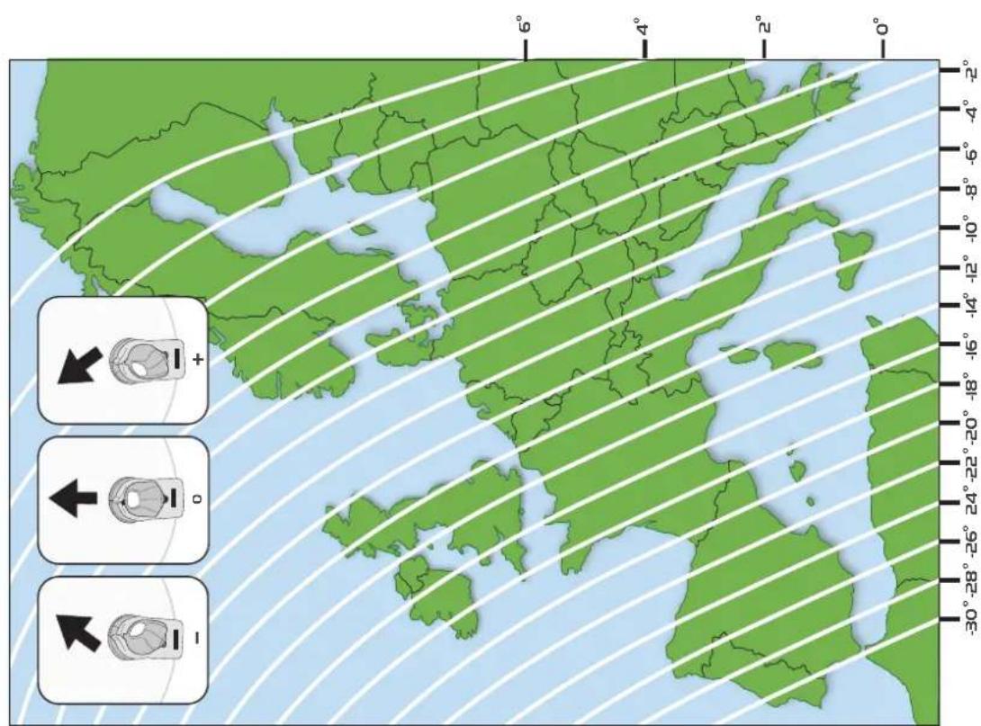
text_image
-30°-28°-26°24°-22°-20°-18°-16°-14°-12°-10°-8°-6°-4°-2° 6° 4° 2° 0°Thank you for purchasing this product, should you have any difficulty using your Portable Satellite Kit please contact our friendly Customer Helpline on (01553) 811000.
Before you use your Omnisat Portable Dish System for the first time you will need to assemble the dish pack.
Please retain these instructions for future reference
text_image
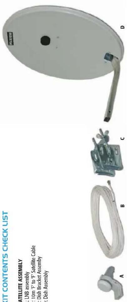
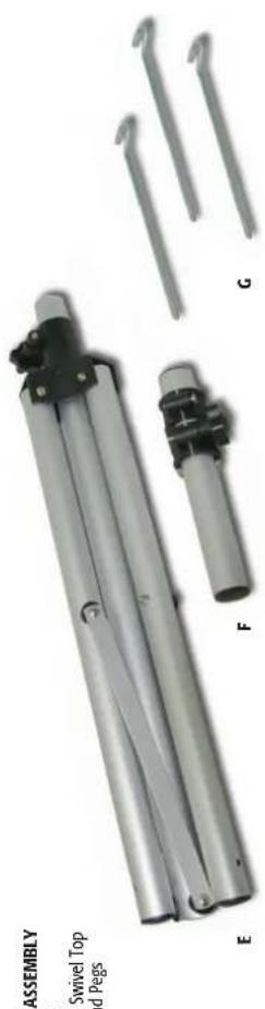
KIT CONTENTS CHECK LIST SATELLITE ASSEMBLY A: LNB assembly B: 10m 'F' to 'F' Satellite Cable C: Dish Bracket Assembly D: Dish Assembly A B C DTRIPOD ASSEMBLY
E: Tripod
F: Tripod Swivel Top
G: Ground Pegs
natural_image
Product photo of a mechanical assembly with labeled parts (E, F, G) and no visible text or symbols on the main components.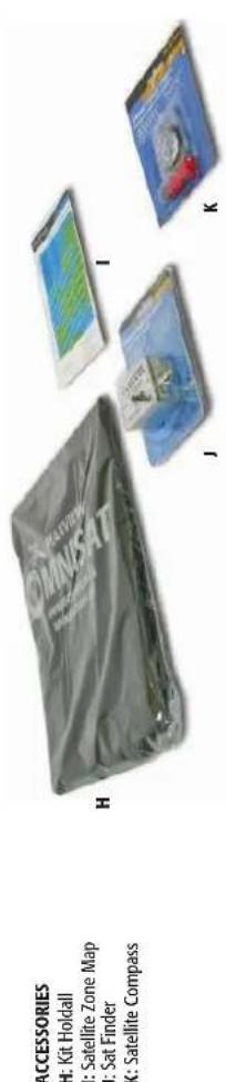
text_image
ACCESSORIES H: Kit Holdall I: Satellite Zone Map J: Sat Finder K: Satellite Compass H I J KRECOMMENDED OPTIONAL EXTRA - NOT INCLUDED.
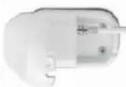
Provides a neat, external weatherproof cable entry point(s) into a caravan or mobile home.
Available in a variety of models. Please see our leisure catalogue or visit us online www.maxview.co.uk
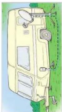
natural_image
Illustration of a yellow van with a satellite dish mounted on a tripod, parked outdoors on grass (no text or symbols)SATELLITE FOOTPRINT INFORMATION
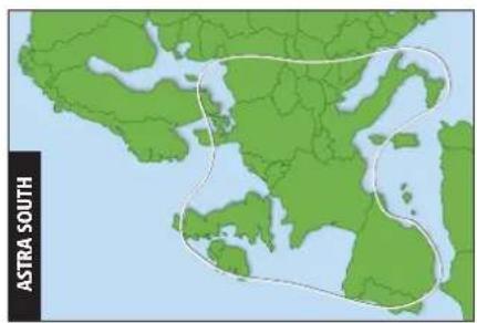
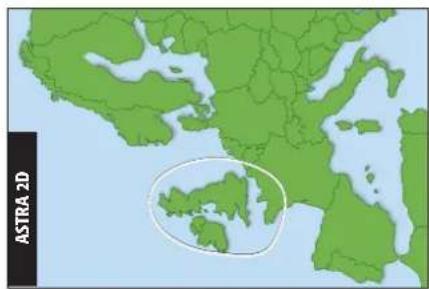
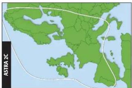
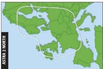
The footprint of a satellite is the ground area where the signal is available and determines the satellite dish size required to receive each transponder's signal. The footprints below show area in which this 54cm dish can receive signals when used with a compatible satellite receiver. Each satellite has its own footprint & beams down it's own channels.
* Only available when using a SKY receiver. Channel listings will be dependent on SKY subscription package.
Note - Use these footprints for general guidance only - Footprint mapping is originally created by SES-ASTRA & EUTELSAT, organisations who own and operate the satellites.
For up to date footprint information visit www.ses-astra.com or www.eutelsat.com
ASTRA 2 South Channels Include...
SKY NEWS
BBC NEWS 2
CNN
SKY CHANNELS* RADIO CHANNEL
...AND MANY MORE
natural_image
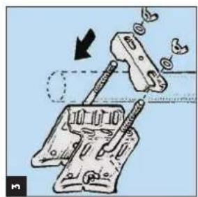
Mechanical assembly diagram showing clamping mechanism with no visible text or symbolsAttach the clamp to the tripod mast and tighten using 2 x M8 Metal Flat Washers and 2 X M8 Wing Nuts.
natural_image
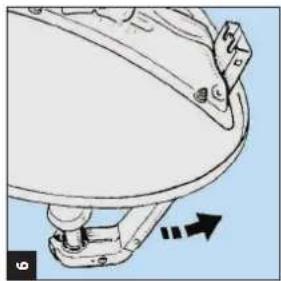
Diagram of a satellite dish antenna with a directional arrow indicating rotation (no text or symbols present)Fold arm down.
text_image
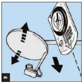
9Point your satellite dish in the direction of the arrow. This will indicate the general direction of the satellite.
Ensure the satellite dish has a clear line of sight to the satellite with no trees or buildings causing an obstruction.
natural_image
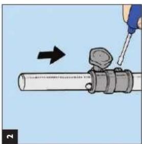
Illustration of a hand using a screwdriver to adjust a cylindrical object with a downward arrow (no text or symbols)Attach rotating mast to tripod using a slotted or cross head screw driver.
natural_image
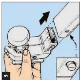
Illustration of a hand using a mechanical clamp to adjust a component, with arrows indicating motion (no text or symbols)Insert LNB assembly into the front of the folding arm. Check that the plastic studs have clicked into place. (Note LNB may look different to the one illustrated).
text_image
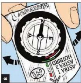
8 ASTRA 1 ASTRA 2 ASTIRID HOUHUARotate the compass until the red end of the needle points North (N) on the compass dial. N.B. The compass must be horizontal and the needle must rotate freely. Allow sufficient time for the needle to react to the rotation. Stand away from metallic objects or electrical appliances.
text_image
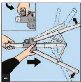
Diagram illustrating a manual tool application on a tripod with directional arrows indicating movement or force, accompanied by an inset image showing a measuring device.Loosen the fixing clamp on the tripod stand and push legs downwards. Extend the feet of the tripod stand as far as they will go for maximum stability. Ensure the tripod is on level ground so the tripod mast is perpendicular to the ground.
text_image
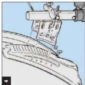
Technical diagram showing mechanical assembly with labeled parts and a tool interacting with a vertical rodAttach satellite dish to bracket. Make sure that bracket slots into grooves of elevation plate. Secure using M6 bolt, washer and wing nut.
text_image
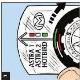
ASTRA 1 ASTRA 2 HOTBIRDUse the Omnisat Compass as an aid to point the satellite dish in a south easterly direction towards the desired satellite. Rotate the black bezel on the compass until the arrow on the clear back plate is in the centre of the coloured line of the desired satellite.
text_image
ASTRA SOUTH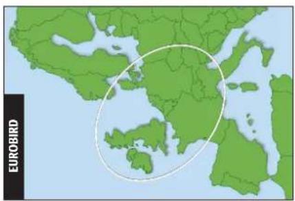
text_image
EUROBIRDEUROBIRD Channels In
MOVIES4MEN, TRUE MOVIES RED ZONE CHANNELS THE VAULT PERFORMANCE BLOOMBERG ...AND MANY MORE
text_image
ASTRA 2DASTRA 2D Channels Include...
ALL BBC CHANNELS ALL ITV CHANNELS CHANNEL 4 FILM 4
FLEM 4 FIVE
SKY CHANNELS*
RADIO CHANNELS ...AND MANY MORE
text_image
ASTRA 2CASTRA 2C Channels Include... SKY CHANNELS* (FIVE US, FIVER)
[Non-Text]
text_image
ASTRA 2 NORTHASTRA 2 North Channels Include... SKY CHANNELS* (SKY BOX OFFICE UKTV SKY SPORTS SKY 1, 2, 3)
natural_image
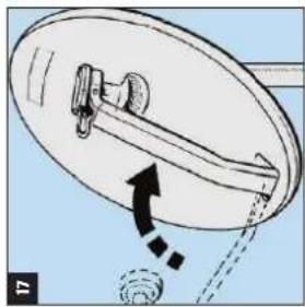
Diagram of a satellite dish with an arrow indicating rotation or movement, no text or symbols presentStowage recommendation (for quick re-assembly).
Fold LNB arm towards dish.
natural_image
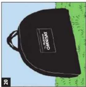
Black and white photo of a black oval backpack with a 'PLOKION OMNISAT' patch, placed on grass (no text or symbols on the bag itself)You can now pack all the separate parts neatly in the kit holdall provided.
Please note there is a pocket located on the font side of the holdall for all your satellite finding accessories.
GUIDELINES FOR SKY DIGITAL SATELLITE RECEPTION
To align the satellite dish to the Astra 2 satellite for digital satellite reception, use the SIGNAL TEST menu built into the SKY digibox. To access this menu you will first have to press the SERVICES button on the remote control. In the SERVICES menu you will then need to access the SYSTEM SET UP (number 4) and the SIGNAL TEST (number 6).
The display will then show, from top to bottom: SIGNAL STRENGTH - SIGNAL QUALITY - LOCK INDICATOR - NETWORK ID -TRANSPORT STREAM You will need to adjust the dish until there is at least a quarter of the SIGNAL QUALITY bar display, the LOCK INDICATOR shows OK and the NETWORK ID is displaying 0002. If the NETWORK ID is showing any other details, you have locked onto the wrong satellite and will need to re-align the dish. When Astra 2 North Beam is being received the TRANSPORT STREAM will display 07d4. This is not the case if receiving South Beam. Press BACK UP.
FOR FREE TO AIR OR FREESAT RECEIVER INSTALLATION INFORMATION PLEASE SEE OPERATING MANUALS
SUPPORT, TERMS & CONDITIONS
This satellite system is guaranteed against defective parts or workmanship for 2 years from time of purchase. (This excludes any malfunction caused by improper use, accidental or malicious damage. This does not affect your statutory rights. If you do experience a problem with the product contact Maxview Customer Services
All instructions and models are subject to change. Maxview reserve the right to alter specifications without prior notice. Copyright ^© . These instructions are the sole property of Maxview Ltd and may not be reproduced. Recycle packaging where facilities exist.
natural_image
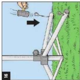
Illustration of a simple outdoor setup with a pole, wooden structure, and a hand holding a container (no text or symbols)For additional stability, the tent pegs supplied can also be used to prevent the stand from falling over in the wind
text_image
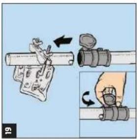
19Loosen the knob on tripod swivel top, then lift off with bracket assembly still attached.
natural_image
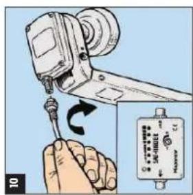
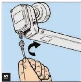
Illustration of a hand using a screwdriver to adjust a mechanical component (no text or symbols visible)Remove the sat finder. Connect the long cable lead to the LNB by screwing the 'F' connector into the underside of the LNB. Ensure the 'F' connector is screwed on tightly.
text_image
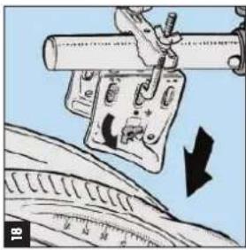
18Loosen the M6 bolt and wing nut on the bracket assembly then remove dish assembly.
text_image
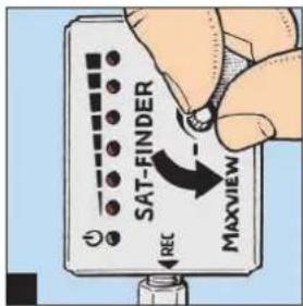
SAT-FINDER REC MAXVIEWSwitch TV and receiver on and the LED marked ⏻ will light up. Turn the signal level control knob anticlockwise to adjust the satellite finder so that the built in buzzer gives a deep tone and the 2nd LED is lit.
text_image
Diagram showing a hand using a tool to adjust or install a device, with arrows indicating motion and labels 14 and 15.Azimuth Alignment
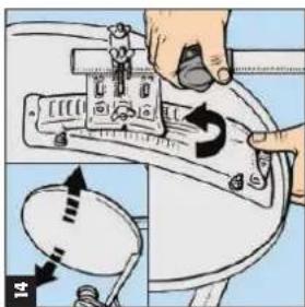
Once the correct elevation angle has been set, loosen the clamp at the top of the mast. Refer to the Omnisat Compass and slowly rotate the dish by turning to the left and then back towards the right within the coloured segment of the desired satellite until you hear a change in tone from the satellite finder.
As the tone and number of red LED's increase, turn the signal level adjustment control anticlockwise to turn the tone down and repeat this fine adjustment until there is no further increase in tone. You may also need to fine tune the elevation to achieve best reception. N.B. Ensure that you continuously turn down the tone as if the tone is too high you will not hear an increase in the tone.
As the satellite finder only determines the reception level and doesn't know from which satellite the signals actually come from, check on the receiver, whether the desired satellite is being received. If this is not the case, continue to search for the next satellite position. If you are receiving signals from the desired satellite, continue to finely adjust the dish until picture is clear.
text_image
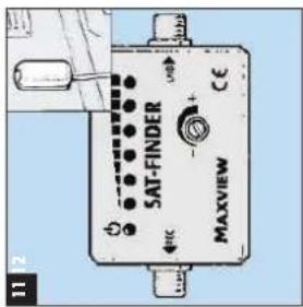
11 2 SAT-FINDER MAXVIEW CEConnect the longer cable to the socket marked 'REC' on the satellite finder and route from the satellite finder to the satellite receiver.
text_image
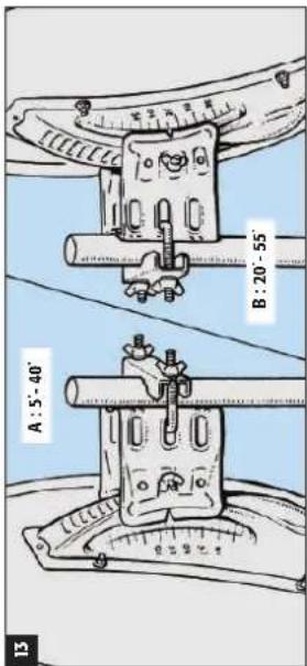
A : 5° - 40' B : 20° - 55'Elevation Alignment
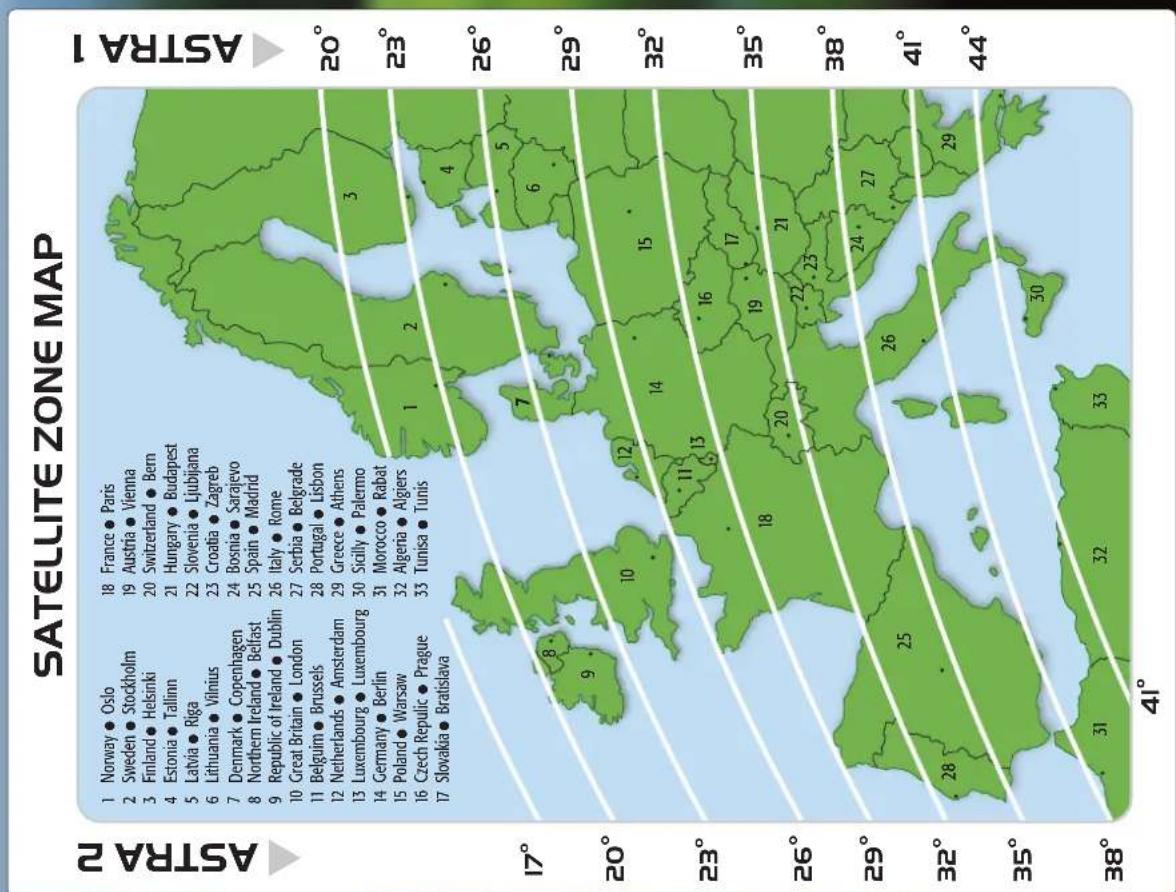
Using zone map provided, identify your position and required angle of elevation. To adjust elevation of dish, line up degrees on the dish braket to the notch on the pole bracket and tighten.
Please note that depending on your location, elevation angle will need to be adjusted. If your location is North adjust elevation angle on the dish marked 5-40'. If South adjust using elevation angle marked 20-55'.
INFORMATION
To receive a clear satellite picture, the dish must have the correct Vertical and Horizontal or Azimuth Alignment.
Vertical alignment is the dish angle of elevation and refers to the angle at which the satellite signals hit the earth's surface. The elevation angle increases the closer you travel to the equator.
Horizontal alignment is the adjustment of the dish in the direction (east or west) of the satellite from which you wish to receive signals. Please note that the dish alignment is critical.
Digital reception produces a substantial delay between receiving a signal and displaying a picture. Therefore small adjustments of the dish should be made in order to allow time for the digital meter in the satellite receiver to respond correctly.
Consult the manufacturer's instruction manual of your satellite receiver for more details.