
TK-390 - Walkie-Talkies KENWOOD - Kostenlose Bedienungsanleitung
Finden Sie kostenlos die Bedienungsanleitung des Geräts TK-390 KENWOOD als PDF.

| Produkttyp | Walkie-Talkie |
| Marke | KENWOOD |
| Modell | TK-390 |
| Abmessungen (H x B x T) | ca. 117 x 56 x 32 mm |
| Gewicht (mit Batterie) | ca. 260 g |
| Stromversorgung | Lithium-Ionen-Akku (7,4 V, ca. 1500 mAh) oder Ni-MH-Akku |
| Frequenzbereich | UHF 400-470 MHz oder VHF 136-174 MHz |
| Sendeleistung | 5 W (einstellbar) |
| Kanäle | 128 Kanäle, 32 Gruppen |
| Funktionen | CTCSS/DCS-Töne, Rauschsperre, Prioritätskanal, Scannen, Notruffunktion |
| Reichweite (abhängig von Umgebung) | bis zu 5 km (im Freien, Sichtverbindung) |
| Schutzart | IP54 (staub- und spritzwassergeschützt) |
| Anzeige | LCD mit Hintergrundbeleuchtung |
| Audioausgang | 500 mW (integrierter Lautsprecher) |
| Zubehöranschluss | 2,5 mm und 3,5 mm Buchsen (Headset, externes Mikrofon) |
| Betriebstemperatur | -25°C bis +60°C |
| Reinigung und Pflege | Mit weichem, trockenem Tuch abwischen; keine aggressiven Reinigungsmittel verwenden |
| Sicherheitshinweise | Nicht in Wasser eintauchen; Akku vor Hitze schützen; nur Original-Netzteil verwenden |
| Ersatzteile | Original KENWOOD-Ersatzteile (Akku, Antenne, Clip, etc.) |
| Reparatur | Reparaturen nur durch autorisiertes Fachpersonal |
Häufig gestellte Fragen - TK-390 KENWOOD
Benutzerfragen zu TK-390 KENWOOD
0 Frage zu diesem Gerät. Beantworten Sie die, die Sie kennen, oder stellen Sie Ihre eigene.
Eine neue Frage zu diesem Gerät stellen
Laden Sie die Anleitung für Ihr Walkie-Talkies kostenlos im PDF-Format! Finden Sie Ihr Handbuch TK-390 - KENWOOD und nehmen Sie Ihr elektronisches Gerät wieder in die Hand. Auf dieser Seite sind alle Dokumente veröffentlicht, die für die Verwendung Ihres Geräts notwendig sind. TK-390 von der Marke KENWOOD.
BEDIENUNGSANLEITUNG TK-390 KENWOOD
KENWOOD
INSTRUCTION MANUAL
VHF FM TRANSCEIVER
TK-290
UHF FM TRANSCEIVER
TK-390
KENWOOD CORPORATION
© B62-0816-20 (K)(MC)
09 08 07 06 05 04 03 02
natural_image
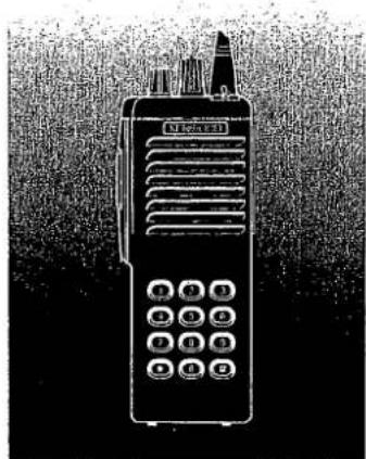
Illustration of a walkie-talkie with control buttons and antenna (no text or symbols visible)THANK YOU!
We are grateful you chose KENWOOD for your land mobile radio applications. We believe this easy-to-use transceiver will provide dependable communications to keep personnel operating at peak efficiency.
KENWOOD transceivers incorporate the latest in advanced technology. As a result, we feel strongly that you will be pleased with the quality and features of this product.
MODELS COVERED BY THIS MANUAL
TK-290: VHF FM Transceiver
TK-390: UHF FM Transceiver
NOTICES TO THE USER
WARNING:
♦ GOVERNMENT LAW PROHIBITS THE OPERATION OF UNLICENSED RADIO TRANSMITTERS WITHIN THE TERRITORIES UNDER GOVERNMENT CONTROL.
♦ ILLEGAL OPERATION IS PUNISHABLE BY FINE OR IMPRISONMENT OR BOTH.
♦ REFER SERVICE TO QUALIFIED TECHNICIANS ONLY.
DO NOT OPERATE YOUR TRANSCEIVER IN EXPLOSIVE ATMOSPHERES (GASES, DUST, FUMES, ETC.).
♦ TURN OFF YOUR TRANSCEIVER WHILE TAKING ON FUEL, OR WHILE PARKED IN GASOLINE SERVICE STATIONS.
SAFETY: It is important that the operator is aware of, and understands, hazards common to the operation of any transceiver.
One or more of the following statements may be applicable:
FCC WARNING
This equipment generates or uses radio frequency energy. Changes or modifications to this equipment may cause harmful interference unless the modifications are expressly approved in the instruction manual. The user could lose the authority to operate this equipment if an unauthorized change or modification is made.
INFORMATION TO THE DIGITAL DEVICE USER REQUIRED BY THE FCC
This equipment has been tested and found to comply with the limits for a Class B digital device, pursuant to Part 15 of the FCC Rules. These limits are designed to provide reasonable protection against harmful interference in a residential installation.
This equipment generates, uses and can generate radio frequency energy and, if not installed and used in accordance with the Instructions, may cause harmful interference to radio communications. However, there is no guarantee that the interference will not occur in a particular installation. If this equipment does cause harmful interference to radio or television reception, which can be determined by turning the equipment off and on, the user is encouraged to try to correct the interference by one or more of the following measures:
• Reorient or relocate the receiving antenna.
- Increase the separation between the equipment and receiver.
- Connect the equipment to an outlet on a circuit different from that to which the receiver is connected.
- Consult the dealer for technical assistance.
CONTENTS
UNPACKING AND CHECKING
EQUIPMENT 1
Supplied Accessories .... 1
INSTALLING THE NICd BATTERY PACK
(OPTIONAL) 2
INSTALLING THE ANTENNA (OPTIONAL) ... 3
INSTALLING THE CAP OVER THE
UNIVERSAL CONNECTOR 3
INSTALLING THE BELT HOOK ...... 3
INSTALLING THE SPEAKER/
MICROPHONE (OPTIONAL) 4
GETTING ACQUAINTED 5
Key Descriptions 6
Display 7
PROGRAMMABLE FUNCTIONS ..... 8
BASIC OPERATIONS....10
Switching Power ON/OFF ..... 10
Adjusting the Volume 10
Selecting a Group 10
Selecting a Channel .... 11
Adjusting the Squeich ..... 11
Making a Call 11
KEY LOCK 12
TIME-OUT TIMER (TOT) 12
SCANNING 12
Priority Scan 13
DTMF CALLING 13
Manual Dialing 13
Redialing 14
Auto Dialing 14
DEALER PROGRAMMABLE
OPTIONS 16
AUDIBLE USER FEEDBACK TONES .... 19
UNPACKING AND CHECKING EQUIPMENT
Note: The following unpacking instructions are for use by your KENWOOD dealer, an authorized KENWOOD service facility, or the factory.
Carefully unpack the transceiver. We recommend that you identify the items listed in the following table before discarding the packing material. If any items have been damaged during shipment, file a claim with the carrier immediately.
■ Supplied Accessories
| Item | Part Number | Quantity |
| Belt hook | J29-0651-XX | 1 |
| Universal connector cap | B09-0363-XX | 1 |
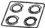
| Channel seal | B03-0594-XX | 1 |
| Channel stopper | D32-0421-XX | 1 |
| Screw set | N99-2004-XX | 1 |
| Warranty card | — | 1 |
| Instruction manual | B62-0816-XX | 1 |
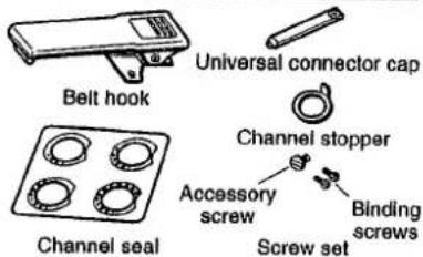


Binding screws
Screw set
图 2
1
INSTALLING THE NiCd BATTERY PACK (OPTIONAL)
The battery pack is not charged at the factory. Charge the pack before use. Repeat the charge/discharge cycles two or three times after purchase or extended storage (greater than 2 months) to bring the battery pack to its normal operating capacity.
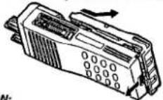
1 Match the four grooves of the battery pack with the corresponding guides on the back of the transceiver.
2 Slide the battery pack along the back of the transceiver until the release latch on the base of the transceiver locks.
3 To remove the battery pack, push down on the release latch and slide the pack away from the transceiver.
CAUTION:
DO NOT RECHARGE THE BATTERY PACK IF IT IS ALREADY FULLY CHARGED. DOING THIS WILL OVERCHARGE THE BATTERY PACK WHICH MAY SHORTEN ITS LIFE OR DAMAGE IT.
♦ AFTER RECHARGING THE BATTERY PACK, DISCONNECT IT FROM THE CHARGER. IF, HAVING RECHARGED THE BATTERY, THE POWER TO THE CHARGER IS TURNED OFF AND THEN BACK ON WHILE THE PACK IS STILL CONNECTED, RECHARGING WILL START AGAIN AND THE BATTERY WILL BECOME OVERCHARGED.
DO NOT SHORT THE BATTERY PACK TERMINALS OR DISPOSE OF THE BATTERY BY FIRE. NEVER ATTEMPT TO REMOVE THE CASE FROM THE BATTERY PACK.
INSTALLING THE ANTENNA (OPTIONAL)
Screw the antenna into the connector on the top of the transceiver by holding the antenna at its base and turning it clockwise until secure.
INSTALLING THE CAP OVER THE UNIVERSAL CONNECTOR
When a speaker/microphone is not being used, install the cap over the universal connector using the supplied accessory screw (4 x 6 mm).
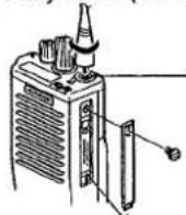
The antenna connector of the transceiver is an SMA male type connector.
Note: To keep the transceiver water resistant, you must cover the universal connector with the cap or the speaker/microphone connector.
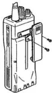
INSTALLING THE BELT HOOK
If necessary, attach the belt hook using the two binding screws (3 x 6 mm) which are supplied in the screw set.
Note: If the belt hook is not installed, its mounting location may get hot during continuous transmission or when left sitting in a hot environment.
natural_image
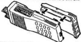
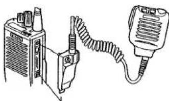
Technical line drawing of a handheld electronic device with ports and connectors (no text or symbols)INSTALLING THE SPEAKER/MICROPHONE (OPTIONAL)
1 Insert the guide of the speaker/microphone connector into the groove on the transceiver universal connector.
natural_image
Line drawing of a portable electronic device connected to a handheld device (no text or symbols visible)A speaker/microphone with an antenna connector is also available.
2 Secure the connector in place using the attached screw.
Note: The speaker/microphone PF keys can be programmed with the functions listed in the table on page 8.
GETTING ACQUAINTED
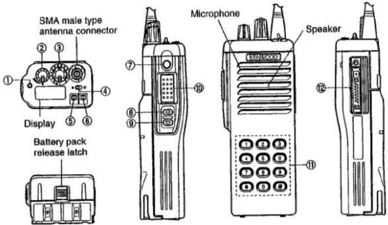
■ Key Descriptions
① TX/Busy/Battery low indicator Lights red while transmitting. Lights green while receiving. Flashes red when the battery power is low while transmitting; replace or recharge the battery. Note: This indicator can be disabled by your dealer (page 16).
② Power switch/Volume control Turn clockwise to switch ON the transceiver. Turn counterclockwise, until a click sounds, to switch OFF the transceiver. Rotate to adjust the volume level.
③ Selector Rotate this control to activate its programmable function (page 8).
④ Toggle switch Switch the toggle position to activate its programmable function (page 8).
⑤ Top 1 ⑥ Top 2 ⑦ Orange ⑧ Side 1 ⑨ Side 2 Press these PF (programmable function) keys to activate their programmable functions (page 8).
⑩ PTT (Push-To-Talk) switch Press this switch, then speak into the microphone to call a station.
⑪ DTMF keypad (keypad models only) Press the keys on the telephone keypad to send DTMF tones.
⑫ Universal connector Connect the external speaker/microphone (optional) here. Otherwise, keep the supplied cover in place.
■ Display
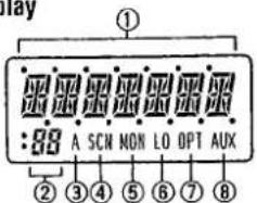
① Alphanumeric display
Displays the operating group or channel number, or the group or channel name. When making a DTMF or 2 Tone call, the display will alternate between CALL and the channel. Also displays various menu functions.
② 7 Segment display
Displays the operating group or channel number. Also displays tA (Talk Around), P1 (Priority1), P2 (Priority2), or HC (Home Channel); depending on the function being used.
③ A (Add) Indicator Appears when a channel is added to the scanning sequence.
④ SCN (Scan) Indicator
Appears when Scan mode is active.
⑤ MON (Monitor) Indicator Appears when the monitor function is active.
⑥ LO (Low) Indicator Appears when low power is selected.
⑦ OPT Indicator
Appears when Operator
Selectable Tone is enabled.
⑧ AUX (Auxiliary) indicator Appears when Aux is ON. Appears and blinks when the optional scrambler board is enabled.
Note: The alphanumeric and 7 segment displays can be inverted if a PF key or the toggle switch is programmed with Invert Display (page 8).
PROGRAMMABLE FUNCTIONS
| Function Name | Selector(3) | ToggleSwitch (4) | PF Keys (5, 6,7,8,9) | Speaker/Microphone PF Keys |
| Aux1 | √ | √ | √ | |
| Channel Down | √ | √ | ||
| Channel Name | √ | √ | ||
| Channel Select | √ | |||
| Channel Up | √ | √ | ||
| Delete/Add | √ | √ | ||
| Emergency Call2 | √ | √ | ||
| Group Down | √ | √ | ||
| Group Scan | √ | |||
| Group Select | √ | √ | ||
| Group Up | √ | √ | ||
| Home Channel | √ | √ | ||
| Invert Display | √ | √ | √ | |
| Key Lock | √ | √ | √ | |
| Lamp | √ | √ | ||
| Low Power | √ | √ | √ | |
| Monitor | √ | √ | √ | |
| Monitor Momentary | √ | √ |
8
| Function Name | Selector (3) | Toggle Switch (4) | PF Keys (5, 6, 7, 8, 9) | Speaker/ Microphone PF Keys |
| No Function | √ | √ | √ | |
| Operator Selectable Tone | √ | √ | ||
| Operator Selectable Priority1 | √ | |||
| Operator Selectable Priority2 | √ | |||
| Scan | √ | √ | √ | |
| Scrambler ^3 | √ | √ | √ | |
| Shift | √ | √ | ||
| SP Attenuation | √ | |||
| Squelch Level | √ | √ | ||
| Squelch OFF | √ | √ | √ | |
| Squelch Momentary | √ | √ | ||
| Talk Around | √ | √ | √ |
^1 This function can be selected when the scrambler board has not been installed.
^2 This function can be selected when the ANI board has been installed.
^3 This function can be selected when the scrambler board has been installed.
Please contact your dealer for details on these functions.
Note:
◆ To program 2 functions onto each PF key and the toggle switch, "Shift" must first be programmed.
◆ Programming the same function onto both a PF key and the toggle switch will cause an error to occur on the PF key.
9
BASIC OPERATIONS
■ Switching Power ON/OFF
To switch ON the transceiver, turn the Power switch/Volume control clockwise until it clicks.
To switch OFF the transceiver, turn the Power switch/Volume control counterclockwise until it clicks.
If the Radio Password function is programmed (page 16), LOCK will appear on the display when the power is turned ON. To unlock the transceiver, enter the password, then press the # key. If the wrong password is entered, an error tone will sound, and the transceiver will remain locked. The password can be a maximum of 6 digits. (This function is available on keypad models only.)
■ Adjusting the Volume
Turn the Power switch/Volume control to adjust the volume. Clockwise increases the volume, and counterclockwise decreases it.
■ Selecting a Group
Turn the Selector, press the Group Up and Group Down keys, or use the toggle switch to select a group.
- Use the Selector, PF keys, or toggle switch, depending on which one is programmed with the group functions.
■ Selecting a Channel
Turn the Selector or press the Channel Up and Channel Down keys to select a channel.
- Use the Selector or PF keys, depending on which one is programmed with the channel functions.
■ Adjusting the Squelch
1 Press the key programmed as Squelch Level.
2 Press the keys programmed as Group Up and Group Down or Channel Up and Channel Down to adjust the squelch level.
■ Making a Call
1 Select the desired group and channel {page 10}.
2 Use the key or switch programmed as Monitor to check whether or not the channel is free.
• If the channel is busy, wait until it becomes free.
3 Press and hold the PTT switch, then speak into the microphone in your normal voice.
- For best results, hold the transceiver approximately 3 to 4 cm (1 1/2 inches) from your lips.
4 Release the PTT switch to receive.
KEY LOCK
Use the key or switch programmed as Key Lock to activate the Key Lock function. When activated, only the PTT and toggle switch, the Selector, and the keys programmed as Emergency Call, Monitor, Monitor Momentary, Squelch OFF, Squelch Momentary, and Lamp can be used.
TIME-OUT TIMER (TOT)
The TOT is used to automatically inhibit transmission after a specified time elapses. If the PTT switch is held down for longer than the programmed time, the transceiver will stop transmitting and a warning tone will sound. To stop the warning tone, release the PTT switch.
Note: TOT settings can be programmed by your dealer (page 16).
SCANNING
Note: The Scan function can be used with a minimum of two channels.
Scan is used to monitor signals on the transceiver channels. When scanning, the transceiver checks each channel for a signal, and stops on a channel if one is present.
Use the key or switch programmed as Scan.
- "SCAN" or the revert group/channel number (depending on which one is programmed by your dealer), and the SCN icon will appear on the display.
• A confirmation tone will sound.
To quit scanning, use the Scan key or switch again.
• Two confirmation tones will sound.
■ Priority Scan
For Priority Scan to function, the Priority1 or Priority2 channel must be programmed.
- If only one of the priority channels are programmed, the transceiver will automatically change to that priority channel when a signal is received on it. This change occurs even if a signal is being received on another channel.
- If both priority channels are programmed, Priority1 is the high priority and Priority2 is the low priority. If a signal is being received on the Priority1 channel, the transceiver will change to that channel, even if a signal is being received on the Priority2 channel.
DTMF CALLING
Note: This function can only be used by transceivers with DTMF keypads.
■ Manual Dialing
To dial a number manually:
1 Press and hold the PTT switch.
- If Keypad Auto PTT is enabled (page 16), you do not need to press the PTT switch.
2 Press the desired DTMF keys.
■ Redialing
A maximum of 16 digits can be redialed. The last number dialed, either manually or automatically, will be redialed.
To redial a number:
1 Press the * key.
• An "A" will appear on the display.
2 Press the 0 key.
- The transceiver will redial the last number, and the digits will appear on the display.
Note: If the transceiver power is switched OFF, the redial memory will be erased.
■ Auto Dialing
Note: Auto dialing is either enabled or disabled by your dealer (page 16).
Store:
To store a number in memory:
1 Press the # key.
• A "D" will appear on the display.
2 Press the desired DTMF keys to enter a maximum of 16 digits.
- Press and hold the PTT switch, then press 2, 5, 8, 0, *, or # to enter A, B, C, D, *, or # (consecutively).
3 Press the # key.
4 Select the desired memory channel by pressing a DTMF key (1 \~ 9).
• The entered number will be stored in the memory channel selected.
Confirm:
To confirm a stored number:
1 Press the # key.
• A "D" will appear on the display.
2 Press the * key.
• "D-" will appear on the display.
3 Press the memory channel key (1 \~ 9) with the stored number you want to confirm.
- The stored digits will appear on the display, and the DTMF tones will sound.
Send:
To send a stored number:
1 Press the * key.
• An "A" will appear on the display.
2 Press the memory channel key (1 \~ 9) with the stored number you want to send.
- The transceiver will begin the transmission, and the digits will appear on the display.
Clear:
To erase a stored number from memory:
1 Press the # key.
• A "D" will appear on the display.
2 Press the # key again.
- "D-CLR" will appear on the display.
3 Press the memory channel key (1 \~ 9) with the stored number you want to erase.
DEALER PROGRAMMABLE OPTIONS
The following/list of functions can be enabled or disabled by your dealer:
| CHANNEL |
| Group Name |
| Receive Frequency |
| Transmit Frequency |
| QT/DQT Decode |
| QT/DQT Encode |
| Channel Name |
| Option Signaling |
| TX Power |
| Wide/Narrow |
| Scan Delete/Add |
| PTT ID |
| Busy Channel Lockout (BCL) |
| Beat Shift |
| Voice Scrambler |
| Priority1 Channel |
| Priority2 Channel |
| Home Channel |
| Emergency Channel |
| EDIT |
| Scan Information |
| Priority1 |
| Priority2 |
| Look Back Time A |
| Look Back Time B |
| Revert Channel |
| Dropout Delay Time |
| Dwell Time |
| Group Scan |
| Priority Channel Quick Scan |
| Priority1 Temp. D/A |
| Priority2 Temp. D/A |
| Temp. D/A Key Hold Time |
| Revert Channel Display |
| Optional Features |
| Channel Text Size |
| Group Text Size |
| Power ON Tone |
| Control Tone |
| Warning Tone |
| Alert Tone |
| Minimum Volume |
| Squelch Level |
| BCL Override |
| Selective Call Alert LED |
| Radio Password |
| Data Password |
| Battery Warning |
| Busy LED |
| TX LED |
| 7 Segment LCD Display |
| Invert Display |
| Emergency Channel Display |
| Clear to Transpond |
| External Speaker |
| Noise Cancel Mic |
| Mode: Self Programming/Panel Test/Clone/Main Programming |
| ID: ID Format/Speed/PTT ID/Dial ID/Connect ID/Disconnect ID |
| Operator Selectable Tone: OST Back Up/ Direct OST/OST Name |
| Group Features |
| Time-out Timer (TOT) |
| TOT Pre-Alert |
| TOT Rekey Time |
| TOT Reset Time |
| Group Delete/Add |
| Battery Save |
| Signaling |
| 2-Tone (1, 2, and 3) |
| Decoder Call Format (1 and 2) |
| Decoder Call Type (1 and 2) |
| Tones (A, B, and C) |
| Alert Tone/Transpond |
| Auto Reset |
| DTMF |
| DTMF Speed (Encode) |
| First Digit Time (Encode) |
| First Digit Delay (Encode) |
| * and # Tone (Encode) |
| DTMF Side Tone (Encode) |
| DTMF Hold Time (Encode) |
| Keypad Auto PTT (Encode) |
| Manual Dial (Encode) |
| Auto Dial (Encode) |
| Auto Dial Programming (Encode) |
| Auto Dial Memory (Encode) |
| Alert Tone/Transpond (Decode) |
| Primary Code (Decode) |
| Secondary Code (Decode) |
| Auto Reset (Decode) |
| Dead Beat Disable (Decode) |
| Embedded Message(64 characters maximum) |
Please contact your dealer for details on these functions.
AUDIBLE USER FEEDBACK TONES
The transceiver outputs various tones to indicate the transceiver operating status.
- Power ON Tone
• Key Operation Tone
• End of Operation Tone
• Operation Error Tone
• Sequence Error Tone
• Transmission Inhibit Tone
• Time-out Timer Warning Tone - Selective Call Alert Tone
- Call Alert (Transpond)
• Dead Beat Disable Tone
• Password Agreement Tone
Please contact your dealer for details on these functions.

- KENWOOD
- INSTRUCTION MANUAL
- THANK YOU!
- MODELS COVERED BY THIS MANUAL
- NOTICES TO THE USER
- WARNING:
- One or more of the following statements may be applicable:
- FCC WARNING
- INFORMATION TO THE DIGITAL DEVICE USER REQUIRED BY THE FCC
- CONTENTS
- UNPACKING AND CHECKING
- UNPACKING AND CHECKING EQUIPMENT
- INSTALLING THE NiCd BATTERY PACK (OPTIONAL)
- CAUTION:
- INSTALLING THE ANTENNA (OPTIONAL)
- INSTALLING THE CAP OVER THE UNIVERSAL CONNECTOR
- INSTALLING THE BELT HOOK
- INSTALLING THE SPEAKER/MICROPHONE (OPTIONAL)
- ■ Key Descriptions
- BASIC OPERATIONS
- ■ Switching Power ON/OFF
- ■ Adjusting the Volume
- ■ Selecting a Group
- ■ Selecting a Channel
- ■ Adjusting the Squelch
- ■ Making a Call
- KEY LOCK
- TIME-OUT TIMER (TOT)
- SCANNING
- ■ Priority Scan
- DTMF CALLING
- ■ Manual Dialing
- ■ Redialing
- ■ Auto Dialing
- Store:
- Confirm:
- Send:
- Clear:
- DEALER PROGRAMMABLE OPTIONS
- AUDIBLE USER FEEDBACK TONES
Marke : KENWOOD
Modell : TK-390
Kategorie : Walkie-Talkies