
P400X1 - Autoradio Rockford Fosgate - Kostenlose Bedienungsanleitung
Finden Sie kostenlos die Bedienungsanleitung des Geräts P400X1 Rockford Fosgate als PDF.


| Produkttyp | Monoblock Subwoofer Verstärker |
| Marke | Rockford Fosgate |
| Modell | P400X1 |
| Kategorie | Autoradio |
| RMS-Leistung bei 4 Ohm | 400 W x 1 |
| RMS-Leistung bei 2 Ohm | 600 W x 1 |
| Maximale Leistung | 1200 W (Spitze) |
| Verstärkerklasse | Klasse D |
| Frequenzgang | 20 Hz – 250 Hz |
| Dämpfungsfaktor | > 100 |
| Eingangsempfindlichkeit | 200 mV – 8 V |
| Eingänge | Cinch (RCA) Low-Level |
| Ausgänge | Lautsprecherklemmen |
| Fernbedienung | Punch Level Control (PLC2 optional) |
| Filter | Variabler Tiefpass 50–250 Hz |
| Equalizer | Punch EQ (0–18 dB Bass-Boost) |
| Betriebsspannung | 10–16 V DC |
| Abmessungen (B x H x T) | ca. 185 x 45 x 140 mm |
| Gewicht | ca. 1,2 kg |
| Gehäusematerial | Aluminium-Kühlkörper |
| Besonderheiten | Input Clip Indicator, Output Clip Indicator |
Häufig gestellte Fragen - P400X1 Rockford Fosgate
Benutzerfragen zu P400X1 Rockford Fosgate
0 Frage zu diesem Gerät. Beantworten Sie die, die Sie kennen, oder stellen Sie Ihre eigene.
Eine neue Frage zu diesem Gerät stellen
Laden Sie die Anleitung für Ihr Autoradio kostenlos im PDF-Format! Finden Sie Ihr Handbuch P400X1 - Rockford Fosgate und nehmen Sie Ihr elektronisches Gerät wieder in die Hand. Auf dieser Seite sind alle Dokumente veröffentlicht, die für die Verwendung Ihres Geräts notwendig sind. P400X1 von der Marke Rockford Fosgate.
BEDIENUNGSANLEITUNG P400X1 Rockford Fosgate

Step 1 - Input
Input Clip Indicator Setup
Be sure to disconnect all speakers
from the amplifier.

CAUTION
Failure to comply may cause damage
to connected components and/or
amplifier.

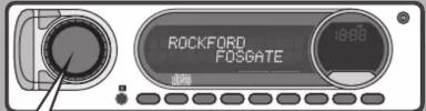
Step 2 - Input
Turn on the source unit with volume set to zero.
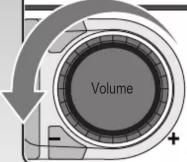
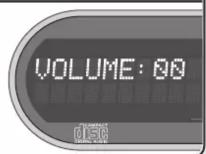
Step 3 - Input
Adjust the Bass & Treble levels on the source unit to flat.

Amplifier Clip Indicator Setup
Step 4 - Input
Play test tone* or music CD for setup.

Note: Use the 40Hz @ 0dB tone (Track 5) for mono amplifier applications or the 1kHz @ 0dB tone (Track 7) for multi-channel amplifier applications. Be sure your x-over is switched to the appropriate filter setting.
*Test tones available at https://rftech.custhelp.com/app/answers/de-
tail/a_id/1126/ Scroll to the bottom of the page and download your preferred
Step 5 - Input
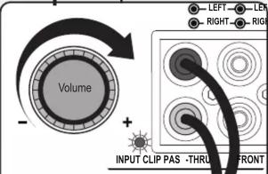
Increase the source unit volume until the Input Clip Indicator illuminates red.
Note: Input Clip can be viewed remotely with optional PLC2.
Step 6 - Input

Decrease the source unit volume slightly until the light turns completely off. This establishes your maximum source unit volume for adjusting the Output Clip Indicator.
Note: Some source units will not clip.

Step 7 - Output
Be sure to disconnect Punch Level Control - PLC (if equipped) from the amplifier.
Step 8 - Output
Output Clip Indicator Setup

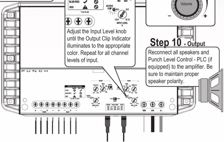
Adjust the Input Level knob until the Output Clip Indicator illuminates to the appropriate color. Repeat for all channel levels of input.
Step 9 - Output
Turn the source unit volume down.


Step 10 - Output
Reconnect all speakers and Punch Level Control - PLC (if equipped) to the amplifier. Be sure to maintain proper speaker polarity.

Rockford Fosgate

Marke : Rockford Fosgate
Modell : P400X1
Kategorie : Autoradio