
LRX 2.9 - Autoradio AUDISON - Kostenlose Bedienungsanleitung
Finden Sie kostenlos die Bedienungsanleitung des Geräts LRX 2.9 AUDISON als PDF.


| Produkttyp | Car-Audio-Verstärker (Stereo-Endstufe) |
| Modell | Audison LRX 2.9 |
| Abmessungen (B x L x H) | 198 x 438 x 56 mm |
| Gewicht | 4,3 kg |
| Betriebsspannung | 11-15 V DC |
| Stromaufnahme (max. Musikleistung) | 65 A |
| Interne Sicherung | 60 A |
| Ausgangsleistung (RMS) @ 14,4 V, 1% THD | Stereo 2x 260 W (4 Ω), Stereo 2x 450 W (2 Ω), Mono 1x 900 W (4 Ω) |
| Frequenzgang (-3 dB) | 4 Hz - 80 kHz |
| Signal-Rausch-Verhältnis (A-bewertet) | 100 dB |
| Dämpfungsfaktor (1 kHz, 4 Ω) | 120 |
| Eingangsempfindlichkeit (PRE IN) | 0,3-5 V |
| Eingangsempfindlichkeit (Speaker IN) | 1,4-24 V |
| Eingangsimpedanz (PRE IN) | 15 kΩ |
| Eingangsimpedanz (Speaker IN) | 5 kΩ |
| Mindestlastimpedanz | 2 Ω (Stereo), 4 Ω (Mono) |
| Frequenzweiche | Bypass / Hochpass / Tiefpass 50-5.000 Hz, 12/24 dB/Okt. (Mono) |
| ECI-Eingangsmodule | Wechselbar und umkehrbar (Low Level / High Level) |
| Besondere Merkmale | Mikroprozessorgesteuerte Schutzschaltungen, Remote-Ein-/Ausgang, automatische Einschaltung über Lautsprecherkabel, Fernbedienung für Subwoofer-Pegel |
| Lieferumfang | Bedienungsanleitung, Garantiekarte, Montageschablone, Abdeckhaube, Kabelclips, Steckverbinder, Ersatzsicherung, Werkzeug |
Häufig gestellte Fragen - LRX 2.9 AUDISON
Benutzerfragen zu LRX 2.9 AUDISON
0 Frage zu diesem Gerät. Beantworten Sie die, die Sie kennen, oder stellen Sie Ihre eigene.
Eine neue Frage zu diesem Gerät stellen
Laden Sie die Anleitung für Ihr Autoradio kostenlos im PDF-Format! Finden Sie Ihr Handbuch LRX 2.9 - AUDISON und nehmen Sie Ihr elektronisches Gerät wieder in die Hand. Auf dieser Seite sind alle Dokumente veröffentlicht, die für die Verwendung Ihres Geräts notwendig sind. LRX 2.9 von der Marke AUDISON.
BEDIENUNGSANLEITUNG LRX 2.9 AUDISON
LRx
The Universal Sound
audison
Manuale d'uso
LRx 2.4
LRx 2.9
Introduzione
Lo spirito innovativo contraddistingue i prodotti di Audison. Da molti anni idee brillanti, soluzioni inedite e funzioni circuitali uniche soddisfano lo spirito di ricerca dei progettisti e l'interesse degli appassionati.
Che altro si poteva fare ancora?
A guardar bene, nel mercato ci sono amplificatori che offrono tanta potenza con dimensioni da rendere complicata l'installazione, quelli che hanno il bel suono ma sono iraggiungibili, quelli che hanno l'ingresso speakers, chi ha la completa copertura a protezione dei cavi etc.
Ebbene, dopo attente analisi, strade percorse ed abbandonate, tecniche meccaniche ed elettroniche controcorrente, è nato un progetto unico, duttili, facilmente aggiornabile per la veloce evoluzione del mercato ma solido nella sua struttura e che, discretamente, nel tempo potrà dirsi rivoluzionario.
Innovativo nell'anima, l'LRx rispecchia l'estro creativo di chi, come lui, ha segnato una pietra miliare nei riferimenti assoluti. Derivato direttamente dall'esperienza fatta con il THESIS HV venti, l'LRx riprende le linee quida e forda la sua rivoluzione nell'innovazione.
ECI (Easy Common Interlace) è la gestone universale degli ingressi fatta con moduli intercambiabili e reversibili. Reversibili per poter nasconcere alla vista i cavi di segnale sotto l'amplificatore siano essi su RCA che ad alto livello; ma possono essere nascosti anche i cavi di potenza e di alimentazione grazie alle apposite mascherine. LRx introduce in un'unica linea di amplificatori anche la gestione a microprocessore delle funzioni vitali. Le protezioni diventano attive, coordinando l'accensione e lo spegnimento dell'alimentazione, l'intervento delle sicurezze, monitorando la temperatura e regolando il sistema di controllo per la stabilizzazione termica dello stadio finale, limitando la tensione di alimentazione in funzione della corrente d'uscita senza intervenire sui segnale. Ogni funzione ha il suo indicatore luminoso, riportato su un pannello protetto e coperto da un guscio in policarbonato. Il pannello accoglie anche i controlli dei crossover completamente indipendenti, escludibili e configurabili nel più ampio range possibile a vantaggio della massima versatilità d'uso. Il layout dei circuiti stessi è oggetto di innovazione con una motherboard in cui è stato ottimizzato il percorso e il dimensionamento delle piste di potenza, è stato separato il modulo di controllo del segnale per eliminare ogni possibile interferenza, è stato utilizzato un driver lineare a differenziale compiementare in casse A. L'insieme è teso al miglior rendimento acustico in qualsiasi situazione. Mettere tutte queste caratteristiche nello stesso amplificatore non è stato facile, ma quale altro procotto può vantarsi di offrire tanto? E a questo livello?
Come tutte le cose innovative, l'LRx potrà sollevare qualche dubbio dovuto alla consuetudine e allora sarà sufficiente guardarlo dentro e fuori, installarlo e ascoitarlo per avere la soddisfazione di possedere qualcosa di speciale, qualcosa che non vuole solo mostrare ma dimostrare.
Gli LRx 2.4 e 2.9 sono amplificatori di potenza stereofonici per auto. La sezione di alimentazione e gli stadi finali, che possono lavorare anche in mono, erogano un'elevatissima corrente d'uscita con potenze comprese fra 135 e 900 W. Ogni dettaglio costruttivo, dai crossover completamente indipendenti ai moduli d'ingresso/uscita ECI, dal controllo remoto del volume all'Auto Turn-ON tramite l'ingresso Speaker, rivela la cura rivolta ai massimo delle prestazioni. Le possibilità di gestione sono infinite per qualsiasi tipologia di installazione, unite a straordinarie prerogative musicali. Le pregevoli qualità timbriche, la notevole riserva di potenza e il costante controllo elettronico dello status operativo lo rendono l'amplificatore ideale per raggiungere elevatissimi livelli di pressione con straordinarie prerogative musicali.
Indice
Introduzione 2
Indice 3 I Contenuto dell'imballo 4
Safe Sound 5 Precauzioni Generali 6
Pannello Ingressi ECI - Easy Common Interface 8 ECI - L Low Level: Pannello Ingressi Preamplificati 8 ECI - H High Level: Pannello Ingressi Alto Livello/Uscite PRE 8 Installazione dei Pannelli Ingressi ECI 9 Quando si monta l'ECI rovesciato 9
Pannello Alimentazione/Uscite/Servizi 10 | Come togliere il guscio 10 Come mettere il guscio 10 Come cambiare la mascherina 11 Esempio di utilizzo delle mascherine 11 Descrizione 12 Come si montano i connettori portafaston 13 Servizi 13 Auto Turn-ON con SPK ON 14 Remote OUT con ECI-H o SPK ON 14 Quando si usa il connattore SUB VOL 14 Come si cambia il fusibile 14
Pannello Controlli | Come toglere il guscio | Come mettere il guscio | Funzioni LRx 2.4 e LRx 2.9 | Out Mode | Level 0.3÷5 V | Filter | LEDS 15 15 15 16 16 17 18 21
Installazione 23 Fissaggio dell'amplificatore 23 Dima di foratura 24 Come far passare i cavi di segnale sotto l'amplificatore 25 Come ruotare la barretta del logo Audison 26
Cavi di connessione 28 | Potenza 28 Alimentazione 28 Eaempio 29
Configurazioni 30 | Configurazione degli ingressi/uscite 30 | Configurazione dei filtri 30
Caratteristiche tecniche 36 Schema a blocchi 37
LRx
The Universal Sound
audison
LRx 2.4
LRx 2.9
Manuale d'uso
■ Contenuto dell'imballo
All'interno della confezione oltre al Vostro LRx 2.4 o LRx 2.9 troverete:
- Questo Manuale
• Il libretto della garanzia
• Dima di foratura per il montaggio
• Guscio protettivo semitrasparente per il Pannello Controlli
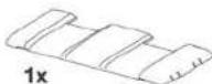
• Mascherina copriterminali con il logo Audison (premontata)
- Mascherina copriterminali sagomata per il passaggio dei cavi
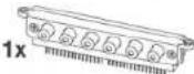
- EGI-L Easy Common Interface - Low Level. Pannello ingressi/uscite preamplificati (premontato)
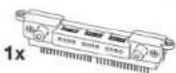
• ECI-H Easy Common Interface - High Level. Pannello ingressi/uscite ad alto livello
- Multispanner Audison
- Clip fermacavo
- Connettori portafaston
- Connettore SUB VOL
• Viti di fissaggio con testa a croce autofilettanti 3,9x16 mm
- Punta per avvitatori specifica con asta allungata.
- Fusibile di ricambio da 40 A (LRx 2.4) o da 60 A (LRx 2.9)




SAFE SOUND

GLI AMPLIFICATORI AUDISON SONO IN GRADO DI CREARE SISTEMI AUDIO AD ALTA POTENZA CHE POSSONO GENERARE ELEVATISSIME PRESSIONI SONORE INDISTORTE, MA RICORDATE CHE PROLUNGATE ESPOSIZIONI AD UN LIVELLO ECCESSIVO DI PRESSIONE ACUSTICA POSSONO PRODURRE DANNI AL VOSTRO UDITO: UTILIZZATE DUNQUE EQUILIBRIO E BUON SENSO NELL'ASCOLTO.
La sicurezza durante la marcia deve restare sempre al primo posto, in ogni situazione il volume d'ascolto deve avere un livello tale da non coprire i suoni provenienti dall'esterno e dovreste essere in condizione di udire anche quelli del vostro veicolo per affrontare prontamente situazioni di emergenza.
Per ottenere il massimo delle prestazioni dal Vostro nuovo amplificatore vi consigliamo di seguire attentamente le istruzioni del presente manuale. La realizzazione di sistemi hi-fi car di alto livello richiede una buona conoscenza delle problematiche meccaniche ed elettriche delle autovetture; qualora riteneste di non avere gli attrezzi necessari o la conoscenza adeguata non esitate a contattare un installatore specializzato. Un'installazione a regola d'arte Vi assicure'ra prestazioni entusiasmanti e coinvolgenti, senza influire sulla sicurezza e l'affidabilità della Vostra autovettura.
Questo manuale è stato pensato per fornire le indicazioni principali e necessarie all'installazione e all'uso dell'amplificatore. Nonostante il gran numero di informazioni e suggerimenti, potrebbe non contenere esattamente le modalità di montaggio per la Vostra particolare autovettura. Se, dopo aver letto questo manuale, aveste ancora delle domande, non esitate a contattare il Vostro rivenditore Audison.
Se aveste bisogno di qualsiasi ulteriore informazione potrete contattare l'assistenza via mail scrivendo direttamente agli indrizzi:
Per l'Italia - supporto.tecnico@elettromedia.it
Per l'estero - support@elettromedia.it
Precauzioni Generali
- Il simbolo a lato indica che è opportuno prestare attenzione alle indicazioni riportate. La mancata osservanza di tali istruzioni potrebbe causare lesioni involontarie o danni all'apparecchio.
- Prima di procedere all'installazione assicuratevi di aver letto con cura e capito tutte le istruzioni.
- L'impianto elettrico del veicolo deve avere una tensione di 12VDC con negativo a massa. Verificate che il veicolo abbia tali caratteristiche per evitare danni sia all'amplificatore che al veicolo stesso.
- Per facilitare l'installazione, prima di tutto programmate la configurazione del Vostro nuovo amplificatore e fate passare i cavi nel modo migliore possibile.
- Indossate sempre occhiali protettivi durante l'utilizzo di attrezzi che possono generare schegge o residui di lavorazione.
- Riponete quando possibile l'amplificatore nell'imballo durante l'installazione, per evitare danni accidentali.
- Fissate alla struttura del veicolo in modo solido e affidabile tramite staffe, viti, dadi e bulloni tutte le strutture supplementari realizzate per installare i vari componenti, per assicurare stabilità e sicurezza in condizioni di marcia.
- Il distaccamento dal fissaggio durante la marcia del veicolo può causare grave danno per le persone trasportate e per gli altri veicoli. Fissate adeguatamente l'amplificatore, facendo la massima attenzione nel caso in cui l'installazione sia all'interno dell'abitacolo. Inserite sistemi di fissaggio supplementari se l'installazione è all'interno del vano motore.
- Spegnete, prima dell'installazione, la sorgente e tutti gli apparati elettronici del sistema audio per evitare qualsiasi possibile danno.
- Assicuratevi che il posizionamento prescelto per i componenti non interferisca con il corretto funzionamento di ogni dispositivo meccanico o elettrico della vettura.
- Evitate di passare i cavi o installare l'amplificatore in prossimità di centraline elettroniche.
- Utilizzate estrema attenzione nel praticare fori o tagli sulla lamiera, verificando che sotto o nella zona interessata non vi sia alcun cavo elettrico o elemento strutturale e vitale per l'autovettura.
- Prima di collegare il cavo di alimentazione all'amplificatore, sconnettete il cavo negativo (-) dalla batteria della Vostra auto.
- Assicuratevi di non cortocircuitare il cavo di alimentazione durante l'installazione e il collegamento.
- Il cavo di alimentazione deve essere provvisto di isolamento meccanicamente resistente ed autostinguente alla famma. La sezione del cavo deve essere adeguata a quanto suggerito nel presente manuale. Nel posizioramento, evitate di schiacciare il cavo contro parti taglienti o nella vicinanza di organi meccanici in movimento. Assicuratevi che sia adeguatamente fissato per tutta la sua lunghezza. Bloccate, tramite un serrafio, il cavo positivo e negativo immediatamente a ridosso dei rispettivi morsetti d'alimentazione dell'amplificatore.
- Proteggete il cavo conduttore con un anello in gomma se passasse in un foro della lamiera o con appositi materiali se scorrono vicino a parti che generano calore.

- Per fissare il collegamento di massa (-) in modo corretto usate una vite già presente sulla parte metallica del veicolo, rimuovete ogni residuo di vernice o grasso se necessario, assicurandovi con un tester che vi sia continuità tra il terminale negativo (-) della batteria e il punto di fissaggio. Se possibile, collegate tutti i componenti allo stesso punto di massa, poiché questa soluzione serve per abbattere la maggior parte dei rumori.
- Fate passare i cavi di segnale tutti insieme ma lontano dai fili d'alimentazione.
- Non fate passare mai i fili all'esterno del veicolo, non avreste protezione sufficiente contro l'usura o in caso d'incidente.
- Nell'installazione degli altoparlanti e dei cavi che li collegano, accertatevi che parti non isolate non vadano in contatto, anche in modo saltuario, con parti taglienti del veicolo. In tal caso interverrà la protezione dell'amplificatore.
- Per evitare problemi, usate cavi, connettori e accessori di alta qualità scegliendoli nel catalogo CONNECTION Audison.
- A fine installazione, ma prima di connettere il fusibile principale di alimentazione, ricontrollate l'intero cablaggio del sistema e assicuratevi di aver eseguito tutti i collegamenti in maniera corretta.
• Gli amplificatori di potenza comportano un ulteriore carico sulla batteria e sul suo sistema di ricarica. E' bene che controlliate le condizioni di alternatore e batteria per assicurarVi che siano in grado di reggere l'incremento di assorbimento. I sistemi elettrici standard in buone condizioni dovrebbero reggere senza problemi, ma VI consigliamo di utilizzare un condensatore ad altissima capacità e/o una batteria specifica per sistemi audio ad alto livello.
- Applicate un fusibile con relativo portafusibile isolato a non più di 40cm dal morsetto positivo della betteria e collegate su di esso il cavo di alimentazione dopo averne collegata l'altra estremità all'amplificatore. Il valore del fusibile deve essere superiore del 50% rispetto a quello posto all'interno dell'amplificatore. Nel caso il cavo alimenti più amplificatori, il fusibile dovrà avere un valore superiore del 50% rispetto alla somma dei valori di tutti i fusibili presenti sugli amplificatori.
- La zona di installazione deve avere un'adeguata circolazione d'aria e non deve essere esposta ad umidità, pioggia, detriti provenienti dall'esterno o dagli organi meccanici del veicolo. Non coprite in alcun modo le prese d'aria per il raffreddamento a circolazione forzata.
- Installare l'amplificatore in zone del veicolo ove la temperatura non scenda sotto gli 0°C (32°F) e non ecceda i 55°C (131°F).
ATTENZIONE. In condizioni particolarmente gravose l'amplificatore può raggiungere temperature fra gli 80 e i 90°C (176÷194°F). Accertatevi che la temperatura non sia pericolosa prima di toccarlo a mani nude.
- Sottoponete a pulizia periodica l'amplificatore evitando l'uso di solventi aggressivi che potrebbero danneggiare le sue varie parti. Utilizzate un panno inumidito con acqua e sapone, strizzatelo e pulite l'amplificatore. Ripassate con un panno inumidito con sola acqua, infine passate un panno asciutto.
- Liberate da polvere e detriti solidi le prese d'aria corrispondenti all'aspirazione e all'uscita. Evitate l'uso di aria compressa direttamente sulle griglie senza smrontarle perché spingerebbe i detriti all'interno. Se necessario, rivolgetevi ad un centro di assistenza specializzato per la pulizia interna. L'ostruzione dei condotti dell'aria provoca l'entrata in protezione termica anticipata dell'amplificatore.
LRx
The Universal Sound
audison
Manuale d'uso
LRx 2.4
LRx 2.9
Pannello Ingressi ECI - Easy Common Interface
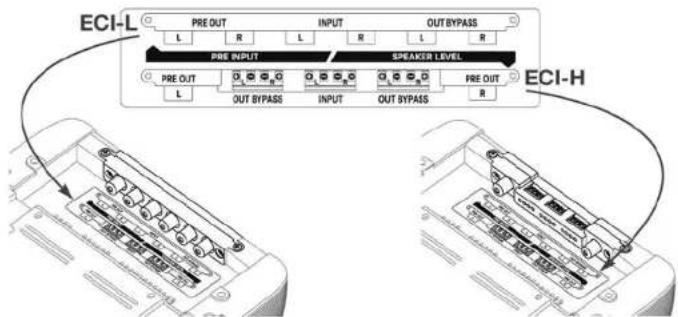
Audison introduce una novità assoluta nella gestione degli ingressi degli amplificatori LRx. ECI è un'interfaccia intercambiabile con una morsettiera comune estremamente facile da utilizzare. Gli LRx sono dotati di un duplice pannello ingressi reversibile che può essere utilizzato a seconda delle esigenze. E' possibile scegliere non solo la tipologia del segnale che dovrà pilotare l'amplificatore tra segnale preamplificato e amplificato, ma qualora ve ne fosse la necessità è possibile fare in modo che i connettori non sporgano dal corpo dell'amplificatore. Basta girare il pannello ingressi e far passare i cavi sotto l'amplificatore nell'apposito incavo. Un'etichetta specifica indica la corretta disposizione degli ingressi e la loro funzione e i cavi possono essere fissati con delle comocie clip.
■ ECI - L Low Level: Pannello Ingressi Preamplificati
1_PRE OUT: Uscite preamplificate
Destra e Sinistra. Il segnale
disponibile su questa uscita è
sottoposto al filtraggio applicato
dalla sezione controlli PRE OUT;
2_ INPUT: Ingressi preamplificati Destro e Sinistro;
3_PRE OUT - BYPASS: Uscite preamplificate
Destra e Sinistra. Il segnale disponibile su questa uscita non è sottoposto a filtraggio ed è quello applicato agli ingressi.
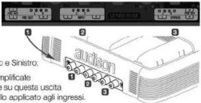
■ ECI - H High Level: Pannello Ingressi Alto Livello/Uscite PRE
- Left PRE OUT: Uscita preamplificata Sinistra. Il segnale disponibile su questa uscita non è sottoposto a filtraggio ed è quello applicato all'ingresso Sinistro;
2_OUT BYPASS (Speaker): Uscite Destra e Sinistra. Il segnale disponibile su questa uscita è quello applicato agli ingressi (Speaker); - Speaker INPUT: Ingressi Destro e il Sinistro per segnali amplificati;
4_OUT BYPASS (Speaker): Lscite Destra e Sinistra. Il segnale disponibile su questa uscita è quello applicato agli ingressi (Speaker);
5_ Right PRE OUT: Uscita preamplificata Destra. Il segnale disponibile su questa uscita non è sottoposto a filtraggio ed è quello applicato all'ingresso Destro;

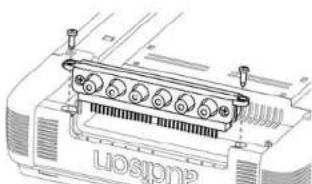
■ Installazione dei Pannelli Ingressi ECI
Per entrambi i pannelli vale la stessa procedura:
■ ECI-L Easy Common Interface - Low Level

■ ECI-H Easy Common Interface - High Level
- Togliere le viti indicate nel disegno;
- Sfilare il pannello tirando con decisione ma facendo attenzione a non piegare i piedini che sono perpendicolari all'amplificatore;
- Sostituire il pannello con quello che si intende utilizzare o girare il pannello mettendo i contatti verso l'interno dell'amplificatore;
4_ Infilare il pannello facendo attenzione all'esatta posizione dei piedini:
5_ Spingere il pannello fino in fondo; - Riavvitare le viti avendo cura di non esagerare con la forza.
■ Quando si monta l'ECI rovesciato
Nel fondo dell'amplificatore, in corrispondenza del pannello ingressi c'è l'etichetta che riporta la corretta disposizione degli ingressi e la loro funzione.

LRx
The Universal Sound
audison
LRx 2.4
LRx 2.9
Manuale d'uso
Pannello Alimentazione/Uscite/Servizi
Il pannello che contiene i terminali di alimentazione e di potenza è protetto da un guscio asportabile e da una mascherina.
■ Come togliere il guscio
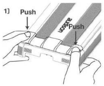
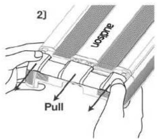
■ Come mettere il guscio

![2] Push to click UOSMIP Push to click](/content/2026/05/766812/images/437c2d4953f8d48af46868a3d0a903bd30dfadc64ef2770e21e86e56bfd7a241.jpg)
10
■ Come cambiare la mascherina
In dotazione con ogni amplificatore ci sono due mascherine, una sagomata per il passaggio dei cavi e una chiusa con il logo Audison per la protezione totale dei cavi di collegamento.
Al momento di reinserire la mascherina far coincidere la linguetta di fig. A con la sede di fig. B
Al momento di reinserire la mascherina far coincidere la linguetta di fig. A con la sede di fig. B
Al momento di reinserire la mascherina far coincidere la linguetta di fig. A con la sede di fig. B
Al momento di reinserire la mascherina far coincidere la linguetta di fig. A con la sede di fig. B
Al momento di reinserire la mascherina far coincidere la linguetta di fig. A con la sede di fig. B
![B] Note](/content/2026/05/766812/images/edf60843f6433e8fce9984bc1c43a44d55f103ff7a4ca6cc5c4c50ac03135222.jpg)
![Note A]](/content/2026/05/766812/images/d572d64ec40c2ef9854405299cb59e8cefd63912d76cbc4e2e75a792115782fe.jpg)
■ Esempi di utilizzo delle mascherine
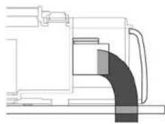
I terminali di alimentazione sono fatti in modo tale da permettere il montaggio anche con la mascherina chiusa. Un'apposita fresatura sul terminale lascia curvare la guaina del cavo

con un andamento naturale. Se l'amplificatore viene montato su un pannello, la dima in dotazione riporta i riferimenti per la foratura per il passaggio dei cavi.
11
Descrizione
-
Fusibile di protezione: 40 A (LRx 2.4) / 60 A (LRx 2.9);
-
Flangia protettiva anticortocircuito;
-
- Power (Ground): morsetto per
il collegamento del polo negativo
d'alimentazione dell'amplificatore.
Collegare qui il cavo negativo
della batteria o un cavo
connesso allo chassis
dell'autoveicolo. Il foro
accetta un cavo della
sezione massima di
A.W.G. 2. Per un miglior
trasferimento della
corrente si raccomanda
di utilizzare cavi della massima
sezione possibile e comunque della stessa
sezione del cavo collegato al polo positivo:
4_ + Power (11÷15 VDC): morsetto per il collegamento
del polo positivo d'alimentazione dell'amplificatore. Collegare
qui il cavo positivo della batteria. Il foro accetta un cavo della
sezione massima di A.W.G. 2. Per un miglior trasferimento della
corrente si raccomanda di utilizzare cavi della massima sezione
possibile e comunque della stessa sezione del cavo collegato al polo
negativo;
-
Left Speaker OUT: Terminale di potenza + e - dell'uscita Speaker Left;
-
Right Speaker OUT: Terminale di potenza + e - dell'uscita Speaker Right;
7_ Remote Sub Volume: Ingressi per il controllo a distanza del volume del Sub, VCRA opzionale.
- Speaker ON: Ingressi per l'accensione dell'amplificatore tramite il cavo di potenza
di un altoparlante. Se la sorgente è priva di un'uscita Remote a 12 VDC, collegare qui una
qualsiasi uscita di potenza, anche in parallelo ad un altoparlante di serie, per accendere l'amplificatore;
- Remote IN/OUT: REM IN, terminale per il collegamento del cavo Remote proveniente
dall'apparecchio che comanda l'accensione dell'amplificatore. La tensione applicata deve essere compresa fra 7 e 16 VDC. REM OUT, terminale per il rilancio della tensione di Remote per accendere altre elettroniche. La tensione d'uscita corrisponde a 12 VDC per 50 mA. Su questo terminale sarà disponibile il comando di accensione per altri apparecchi anche se non viene collegato il REM IN, ma si utilizza la presa Speaker ON.
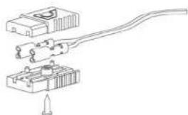
■ Come si montano i connettori portafaston
Servizi
![graph TD A["Sun icon"] --> B["Amplifier"] B --> C["Speaker"] C --> D["ON"] D --> E["Audio output"] style A fill:#f9f,stroke:#333 style B fill:#ccf,stroke:#333 style C fill:#cfc,stroke:#333 style D fill:#fcc,stroke:#333 style E fill:#ffc,stroke:#333](/content/2026/05/766812/images/afefa9d833aac083b369b8f4e2e66512c4d261c1b75ee79b08ae03e2339aae38.jpg)
![graph TD A["Power Supply"] --> B["Remote IN-OUT"] B --> C["Output to audio"] D["Remote In-OUT"] --> E["Resistors: SUB VD, SFE, ON, REM OUT"] E --> F["Resistors: REM OUT, REM IN"] F --> G["Resistors: REM OUT, REM IN"] G --> H["Output to audio"] I["External Circuit"] --> J["Switch 12"] J --> K["Switch…](/content/2026/05/766812/images/c123b30d3deac77f5258f3958d2519426dac8a4d30bcffe9a8498279750ce70c.jpg)
![graph TD A["Speaker ON"] --> B["Amp OFF"] B --> C["Output"] D["OFF"] --> E["Switch"] E --> F["Ground"] G["10"] --> H["Switch"] H --> I["Output"] J["12"] --> K["Switch"] K --> L["Output"]](/content/2026/05/766812/images/5c6b169ea7e357c621cc3f5847c63f8a06d9b86978845ecd32d6c019dac6428a.jpg)
LRx
The Universal Sound
audison
LRx 2.4
LRx 2.9
Manuale d'uso


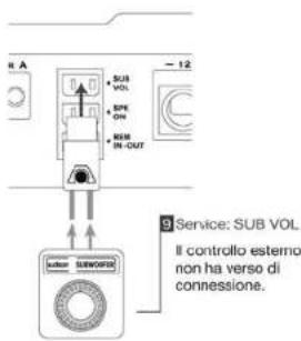
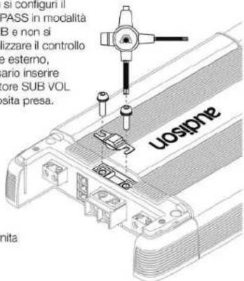
Quando si usa il connettore SUB VOL
Nel caso si configuri il filtro LO-PASS in modalità L+R 24dB e non si voglia utilizzare il controllo di volume esterno, è necessario inserire il connettore SUB VOL nell'apposita presa.
■ Come si sostituisce il fusibile
Dopo aver tolto il guscio protettivo, rimuovere il fusibile con la chiave a brugola fornita con il multispanner in dotazione.
Pannello Controlli
Il pannello che contiene i controlli dell'amplificatore è protetto da un guscio asportabile.
■ Come togliere il guscio
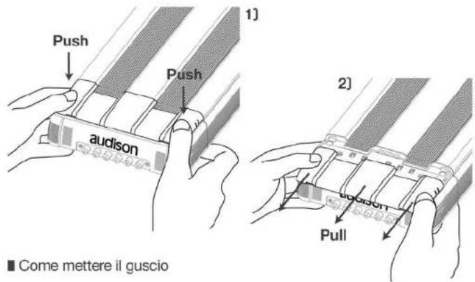

LRx
The Universal Sound
audison
LRx 2.4
LRx 2.9
Manuale d'uso
■ Funzioni LRx 2.4 e LRx 2.9
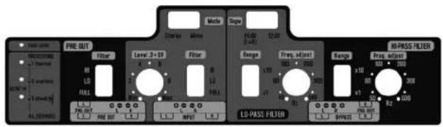
■ Pannello Controlli LRx 2.4 e LRx 2.9
■ Out Mode

![graph LR A["Filtered PRE OUT"] --> B["BYPASS, HI-PASS OR LO-PASS 12 dB FILTER"] C["INPUT L&R"] --> B D["OUT BYPASS"] --> B B --> E["Right Speaker"] B --> F["Left Speaker"] E --> G["Mono L + R"] F --> G](/content/2026/05/766812/images/bb23d2d99236de7e53d71cb836f7d879df8a474d2777a1be18cec0b72dc0b905.jpg)
![graph LR A["Filtered PRE OUT"] --> B["BYPASS, HI-PASS OR LO-PASS 24 dB FILTER"] C["INPUT L&R"] --> B D["OUT BYPASS"] --> B B --> E["Mono L + R"] B --> F["Mono L + R"] E --> G["Mono L + R"] F --> G](/content/2026/05/766812/images/1998d1ef4af47939203e84df9961429940cfc05660a8e80a53ee8af702c74772.jpg)
16
![graph LR A["Filtered PRE OUT"] --> B["PRE OUT FILTER"] C["INPUT R"] --> B D["OUT BYPASS"] --> B B --> E["BYPASS, HI-PASS OR LO-PASS FILTER"] E --> F["Mono L + R"] F --> G["Mono Mode"]](/content/2026/05/766812/images/58418d964bd145bc2630aeaddf8eb8d111b406a927f5e72ffd9ec481ad88b452.jpg)
Level 0.3÷5 V
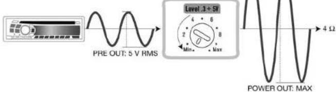
Regolare la sensibilità di ingresso in maniera corretta vuoi dire adattare la sezione d'ingresso al segnale proveniente dalla sorgente, ma soprattutto riuscire a sfruttare tutta la potenza indistorta dell'amplificatore.

17
LRx
The Universal Sound
audison
LRx 2.4
LRx 2.9
Manuale d'uso
Filter
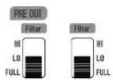
Gli LRx stereofonici hanno una sezione di filtro versatile e indipendente.
Una volta scelta la configurazione dell'uscita di potenza del finale, è possibile regolare l'uscita PRE a proprio piacimento, a tutto vantaggio della facilità d'uso.
Config. 1, 2, 3
AMP FULL
Config. 1, 4, 7
PRE OUT FULL
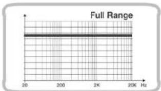
AMP HI 12 dB
Config. 4, 5, 6
PRE OUT HI 12 dB
Config. 2, 5, 8

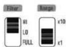


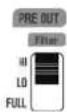
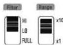

18
AMP LO 12 dB
Config. 7, 8, 9
PRE OUT LO 12 dB
■ Config. 3, 6, 9
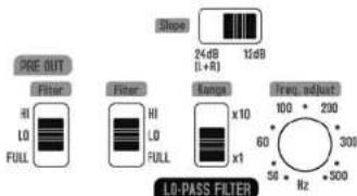
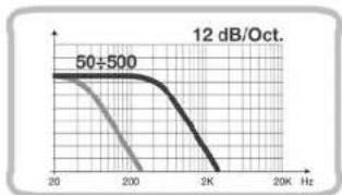
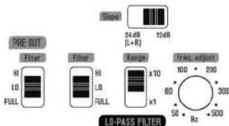
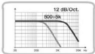
Con il selettore Filter su FULL, l'uscita di potenza dell'amplificatore non è sottoposta a filtraggio. Spostando la selezione su HI si filtra con un passa-alto e pendenza a 12 dB/Oct. In modalità LO sarà possibile scegliere di tagliare il segnale passa-basso a 12 dB/Oct. o a 24. Tali regolazioni sono valide anche per l'uscita PRE OUT che può essere impostata indipendentemente dalla sezione amplificata. Qualora si configuririno le sezioni AMP e PRE OUT nello stesso modo, HI o LO, la frequenza di taglio sarà la stessa per entrambe in quanto gestita dallo stesso filtro.
19
LRx
The Universal Sound
audison
LRx 2.4
LRx 2.9
Manuale d'uso
AMP LO 24 dB
Config. 7, 8, 9
PRE OUT LO 24 dB
Config. 3, 6, 9
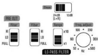


Collegando gli ingressi stereofonici e impostando la sezione di filtro su 24 dB (L+R), alle uscite di potenza sarà presente, su entrambi i terminali, un segnale monofico dato dalla somma di L+R. Sarà bene collegare un carico non inferiore ai 4 Ω ai morsetti configurati in mono (+L e -R).
Alle uscite PRE OUT e BYPASS sarà presente comunque un segnale monofonico dato dalla somma di L+R. Il segnale è prelevabile indifferentemente dal connettore L o R.
LEDS


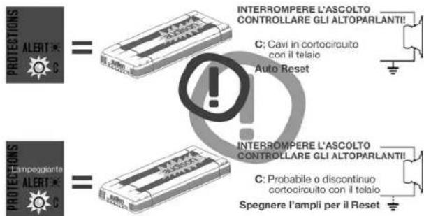
■ Protection LEDS


CONTROLLARE LA TEMPERATURA DELL'AMBIENTE
T: Protezione termica Amp in Limiting -1,5 dB W

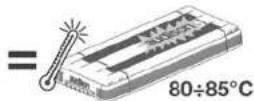
CONTROLLARE LA TEMPERATURA DELL'AMBIENTE
T: Protezione termica Amp in Limiting -3 dB W


CONTROLLARE LA TEMPERATURA DELL'AMBIENTE
T: Protezione termica Auto Reset @ <75° C


CONTROLLARE IL CARICO TOTALE DEGLI ALTOPARLANTI
O: Protezione da sovraccarico Amp OFF, Auto Reset



CONTROLLARE IL CARICO TOTALE DEGLI ALTOPARLANTI
O: Amp in LIMITING Probabile sovraccarico temporaneo

Spegnere l'ampli per il Reset


PROBLEMA INTERNO
Possibilità di alta distorsione udibile Amp OFF

Installazione
■ Fissaggio dell'amplificatore
Per un montaggio totalmente a scomparsa, la sede delle viti è all'interno del perimetro di installazione. Fissate le viti facendo uso della punta per avvitatori specifica con asta allungata in dotazione all'ampificatore.

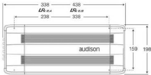
LRx
The Universal Sound
audison
Manuale d'uso
LRx 2.4
LRx 2.9
■ Dima di foratura
![graph TD A["Power Supply Cable Hole Area"] --> B["Services Hole Area"] B --> C["Perimetro per il montaggio a filo del pannello Non-Projecting Outline"] B --> D["Perimetro per il montaggio semi-incassato Semi-Projecting Outline"] B --> E["Perimetro esterno External Outline"] F["Speaker Cable Hole Are…](/content/2026/05/766812/images/575ee76594c9ea3e2fcbcd9ab35f90d50cf9ac81d0a7b37879f8f7c9a98ed452.jpg)
In dotazione è fornita una dima che consente di prevedere le dimensioni di montaggio. Sul cartoncino sono riportate le indicazioni per l'installazione dell'amplificatore a filo del pannello o semi-incassato o su una superficie piara. Nel caso si vogliano montare i cavi completamente a scomparsa si può far riferimento ai fori indicati.
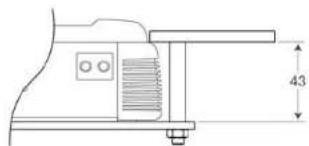
■ Montaggio a filo del pannello

■ Montaggio semi-incassato

24
■ Come far passare i cavi di segnale sotto l'amplificatore
Se si utilizzano i cavi di interconnessione CONNECTION Audison dopo aver collegato i connettori RCA fissare l'Y BLOCK su uno dei pioli predisposti.
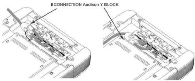
Stendere il cavo nel sito dedicato e fissarlo con le apposite clip fornite in dotazione.
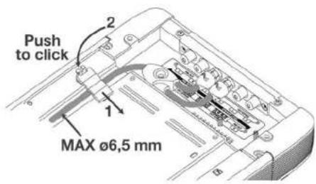
Per fissare la clip fissacavo inserire prima la linguetta, poi schiacciare la clip fino a sentire lo scatto.
25
LRx
The Universal Sound
audison
LRx 2.4
LRx 2.9
Manuale d'uso
■ Come ruotare la barretta del logo Audison


LRx
The Universal Sound
audison
Manuale d'uso
LRx 2.4
LRx 2.9
Cavi di connessione
Utilizzate sempre cavi nuovi e di qualità, con la guaina protettiva integra e che non presentino segni di ossidazione del rame. Per ottenere sempre il massimo dal vostro nuovo amplificatore tenete in considerazione la lunghezza del collegamento e il carico applicato o la corrente che deve portare. I prodotti CONNECTION Audison sono scuramenti i più versatili e completi, studiati e realizzati per far rendere al massimo qualsiasi installazione in abbinamento con gli amplificatori Audison.
Potenza
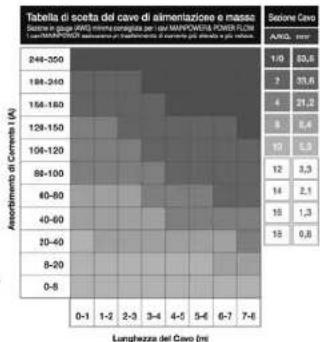
La tavola si riferisce alla potenza continua su un carico di 4 ohm. Qualora il carico scenda si covranno aumentare proporzionalmente le dimensioni del cavo.

Alimentazione
Individuate l'assorbimento di corrente sulla colonna di sinistra della tabella. Individuate il valore di lunghezza del collegamento da effettuare nella colonna alla base della tabella. Nella casella corrispondente a questi due valori potrete leggere la sezione in gauge (AWG) minima consigliata da CONNECTION per la realizzazione di un sistema di elevate prestazioni ed affidabilità.
Come calcolare l'assorbimento
di corrente del vostro sistema
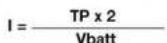
I = Assorbimento di corrente del vostro sistema (A);
TP = Polenza totale (RMS) di tutti i canali degli amplificatori del vostro sistema
Vbatt = Questo valore è di solito pari a 12 V, tensione nominale del sistema elettrico dei veicoli.
Esempio:
- La potenza totale del sistema considerando tutti i canali degli amplificatori è 650 W (RMS).
- L'efficienza media degli amplificatori è circa del 50%, come la maggior parte degli amplificatori in commercio.
- La tensione del sistema elettrico è 12 Vol
I = 650 × 2/12 = 108.3 Assorbimento di Corrente
Esempio
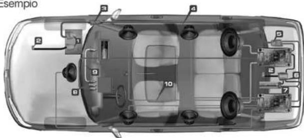


The Transfer System
Cavi di alimentazione Cavi di massa Cavi altoparlanti
Cavi subwoofer interconnessioni audio interconnessioni video
1 MORSETTI PER BATTERIA: assicurano il trasferimento di correnti elevate senza perdite di potenza ed in tutta sicurezza.
2 TERMINALI DI MASSA: riducono al minimo la resistenza del contatto di massa e di conseguenza le perdite di potenza derivanti da un inadeguato collegamento delle masse di potenza del sistema.
3 PORTAFUSIBILI: sono i primi elementi di protezione del vecolo e del sistema da pericolosi cortocircuiti e/o sovraccarichi di corrente. L'involucro in policarbonato ad alta temperatura e la costruzione a tenuta stagna garantiscono affidabilità in ogni condizione ambientale.
4 CAVI DI ALIMENTAZIONE E DI MASSA: sono di fondamentale importanza per ottenere delle prestazioni di "riferimento" dal vostro sistema Car Audio/Video. La speciale tecnologia costruttiva dei cavi MAINPOWER e POWER FLOW riduce l'effetto pelle e consente un trasferimento di elevate correnti impulsive, permettendovi di godere tutta la dinamica della vostra musica.
5 DISTRIBUTORI DI CORRENTE: Il nome identifica immediatamente la funzione cui sono preposti: trasferire energia alle elettroniche. Disponibili in diverse versioni, anche modulari, possono ospitare il fusibile di prctezione. I distributori divengono assolutamente necessari in ogni impianto dove sia richiesto il trasferimento di un'alta quantità di corrente senza perdite.
6 DISTRIBUTORI DI MASSA: sono importanti per le prestazioni del vostro sistema quanto i distributori di potenza. Un unico punto di massa, a bassa resistenza, riduce il rischio di dannose differenze di tensione tra i componenti e migliora il trasferimento di elevate correnti senza perdite di potenza.
7 SUPERFARAD™: i condensatori agiscono come una "riserva di corrente", immagazzinano energia per poi cederla nei momenti di bisogno agli amplificatori incrementando le doti di potenza e dinamica del vostro sistema.
8 INTERCONNESSIONI AUDIO: sono il primo mezzo di trasferimento cel segnale audio del vostro sistema. Per una riproduzione fedele, esse devono trasferire il segnale dalla sorgente agli amplificatori senza alterare il suono ed assicurando, allo stesso tempo, la massima reiezione dei disturbi generati dai dispositivi elettronici a bordo della vostra auto.
9 INTERCONNESSIONI VIDEO: garantiscono un trasferimento dell'immagine con straordinario dettaglio e definizione. L'impedenza costante di 75 ohm lungo tutto il conduttore ed un'efficace schermatura assicurano un'eccezionale qualità delle immagini con la totale assenza di interferenze.
10 CAVI PER ALTOPARLANTI: costituiscono l'ultimo anello del sistema di connessioni per la riproduzione ad alta fedeltà della vostra musica. Garantiscono un trasferimento del segnale ai vostri altoparlanti privo di alterazioni elettrico-musicali e perdite di potenza.
LRx
The Universal Sound
audison
LRx 2.4
LRx 2.9
Manuale d'uso
Configurazioni
■ LRx 2.4 e LRx 2.9
Per l'impostazione degli switch sul pannello di controllo, fate riferimento agli schemi della sezione Filter di pagina 17 e seguenti.
■ Configurazione dei filtri
Le modalità di funzionamento prevedono la possibilità di gestire, in modo indipendente, un filtro passa-tutto, passa-alto o passa-basso sia verso l'amplificatore che verso l'uscita PRE OUT. Solo nel caso in cui l'amplificatore e l'uscita PRE OUT siano configurate con la stessa tipologia, il taglio di frequenza sarà unico.
■ Configurazione degli ingressi/uscite
In modalità stereofonica: quando si utilizza l'INPUT in stereo e il filtro in HI-PASS e LO-PASS 12 dB, alle uscite PRE OUT e all'uscita amplificata sarà disponibile un segnale filtrato passa-alto o passa-basso stereofonico; quando il filtro è in posizione LO-PASS 24 dB alle uscite PRE OUT e all'uscita amplificata sarà disponibile un segnale filtrato passa-basso monofonico in quanto sarà applicato un sommatore Mix L+R. In modalità monofonica è abilitato il solo ingresso Right. Con qualsiasi tipo di filtro alle uscite PRE OUT e all'uscita amplificata sarà disponibile un segnale monofonico. Al'uscita BYPASS sarà presente al connettore Right lo stesso segnale dell' INPUT R.
| Config | AMP | PRE OUT |
| 1 | ||
| 2 | ||
| 3 | ||
| 4 | ||
| 5 | ||
| 6 | ||
| 7 | ||
| 8 | ||
| 9 |
| INPUT | FILTER | PRE OUT | BYPASS | AMP | ||
| Stereo | L & R | HI/LO-PASS12 dB | L & RFiltered | L & RBypass | L & RFiltered | |
| L & R | LO-PASS24 dB | L + RFiltered | L + RBypass | L + RFiltered | ||
| Mono | R | HI/LO-PASS12/24 dB | RFiltered | RBypass | MonoFiltered | |
30
■ 2 vie monoamplificato
![graph TD A["Input (ECI-L or ECI-H) FRONT"] --> B["PRE OUT Optional use"] B --> C["Left"] B --> D["Right"] E["FRONT LEFT"] --> F["Ground"] G["FRONT RIGHT"] --> H["Ground"]](/content/2026/05/766812/images/af20c2d84d9c6ede4454c25fad5ce262dda24761f60e9f1a9ccf6fa662d75274.jpg)
■ 2 vie + Sub in trimode
![graph TD A["Input (ECI-L or ECI-H) FRONT"] --> B["FRONT LEFT"] A --> C["FRONT RIGHT"] B --> D["Left"] C --> E["Right"] D --> F["SUB MONO"] E --> F G["PRE OUT Options use LR2.4 LR2.8"] --> H["Left"] G --> I["Right"] J["Left + - 4Ω"] --> K["Sub MONO"]](/content/2026/05/766812/images/c76a2b5c9daa4920acee01705a00bc035661559138281cd22937e2b0278ef7c9.jpg)
31
![graph TD A["INPUT (ECI-L or ECI-H) FRONT"] --> B["FRONT LEFT"] B --> C["PRE OUT\nOptional use\nLR2.4\nLR2.9"] C --> D["LEFT"] C --> E["Right"] F["INPUT (ECI-L or ECI-H) Stereo"] --> G["FRONT RIGHT"] G --> H["SUB"] H --> I["HI-PASS PRE OUT\nLR2.13k"] I --> J["Left"] I --> K["Right"]](/content/2026/05/766812/images/3f820bd2559df54e298a7d617ffab46f33f9593b6b0a4e79f84c533f2beea28d.jpg)
![graph TD A["FRONT"] --> B["INPUT (ECI-L or ECI-H) FRONT"] B --> C["PRE OUT"] C --> D["FRONT LEFT"] C --> E["FRONT RIGHT"] F["SUB"] --> G["INPUT (ECI-L or ECI-H) REAR"] G --> H["PRE OUT Optional use"] H --> I["FRONT LEFT"] H --> J["FRONT RIGHT"] K["SUB"] --> L["INPUT (ECI-L or ECI-H) Stereo"] M["FRON…](/content/2026/05/766812/images/908e04c64233319482195600a98df5315addb41b4dba1383dac4d08732a3f548.jpg)
■ 3 vie multiamplificato + Sub
![graph TD A["Input (ECI-L or ECI-H) FRONT"] --> B["MID-HIGH LEFT"] A --> C["MID-HIGH RIGHT"] B --> D["PRE OUT Optional use LR-2.4"] C --> E["PRE OUT Optional use LR-2.8"] D --> F["Left"] E --> G["Right"] H["WOOFER LEFT"] --> I["Parallel Connection 2 Ω"] I --> J["Left"] K["WOOFER RIGHT"] --> L["Parall…](/content/2026/05/766812/images/73d705aa9aba9fb66d39e69a6d4c803525cde9ccbae902e2e395e340c24f3ad1.jpg)
■ 3 vie Front multiamplificato attivo + Rear + Sub
![graph TD A["IN A Ch (ECI-L or ECI-H) MID-HIGH"] --> B["PRE OUT Optional use"] B --> C["LR_4.5 OUT MODE 4 Ch"] C --> D["A Left"] C --> E["A Right"] F["MID-HIGH LEFT"] --> G["B Left"] F --> H["B Right"] I["INPUT (ECI-L or ECI-H)"] --> J["WOOFER"] J --> K["BYPASS"] K --> L["LR_2.9"] M["WOOFER LEFT"] --…](/content/2026/05/766812/images/fd1a21cb437b19552ad51aef1795ed2debf43d502ebd0d0458b41fb1b795de42.jpg)
34
■ Multiamplificazione attiva: Front 3 vie + Rear 2 vie + Sub
![graph TD A["Input"] --> B["FRONT TWEETER LEFT"] A --> C["FRONT TWEETER RIGHT"] A --> D["FRONT MIDRANGE LEFT"] A --> E["FRONT MIDRANGE RIGHT"] A --> F["FRONT WOOFER LEFT"] A --> G["FRONT WOOFER RIGHT"] A --> H["Parallel Connection 2 Ω"] A --> I["Parallel Connection 2 Ω"] A --> J["IN A Ch"] A --> K["I…](/content/2026/05/766812/images/06a2fad73b06115539fdd2be1d3068d72bc8101909cddebb681afeb7c08dbcf8.jpg)
35
Caratteristiche tecniche
| LR×2.4 | LR×2.9 | |
| Sezione dalimentazione | ||
| Tensione | 11÷15 VDC | 11÷15 VDC |
| Assorbimento minimo | 1.3 A | 1.7 A |
| Assorbimento da spento | 0.02 mA | 0.02 mA |
| Assorbimento @ 14.4 VDC(Potenza musicale MAX) | 36 A | 65 A |
| Tensione di Remote IN | 7÷15 VDC (1 mA) | 7÷15 VDC (1 mA) |
| Tensione di Remote OUT | 12 VDC (50 mA) | 12 VDC (50 mA) |
| Fusibile interno | 40 A | 60 A |
| Sezione d'amplificazione | ||
| Distorsione - THD (1 kHz @ 4 Ω) | 0,04% | 0,04% |
| Banca passante (-3 dB) | 4±80k Hz | 4±80k Hz |
| Rapporto S/N (pesato A @ 1 V) | 100 dB | 100 dB |
| Fattore di smorzamento (1 kHz @ 4 Ω) | 120 | 120 |
| Sensibilità d'ingresso (PRE IN) | 0.3±5 V | 0.3±5 V |
| Sensibilità d'ingresso (Speaker IN) | 1.4÷24 V | 1.4÷24 V |
| Impederza d'ingresso (PRE IN) | 15 kΩ | 15 kΩ |
| Impederza d'ingresso (Speaker IN) | 5 kΩ | 5 kΩ |
| Impederza di carico (MIN) | ||
| • 2 Ch | 2x2 Ω | 2x2 Ω |
| • 1 Ch | 1x4 Ω | 1x4 Ω |
| Potenza d'uscita Nominale (RMS) | ||
| PN @ 12 VDC; THD 0.3% | 120 W x 2 Ch | 210 W x 2 Ch |
| Potenza d'uscita (RMS) @ 14.4 VDC; THD 1% | ||
| • Stereo 2 Ch x 4 Ω | 130 W x 2 | 260 W x 2 |
| • Stereo 2 Ch x 2 Ω | 230 W x 2 | 450 W x 2 |
| • Mono 1 Ch x 4 Ω | 460 W x 1 | 900 W x 1 |
| Sezione Ingressi / Uscite / Filtri | ||
| Mode | Mono / Stereo | Mono / Stereo |
| Input | PRE / Speaker | PRE / Speaker |
| OUT (Filtered) | PRE | PRE |
| OUT (Bypass) | PRE / Speaker | PRE / Speaker |
| Filter | Bypass / Hi-pass / Lo-pass 50 ÷ 5k Hz @ 12 / 24(mono) dB/Oct. | |
| PRE OUT Filter | Bypass / Hi-pass / Lo-pass 50 ÷ 5k Hz @ 12 / 24(mono) dB/Oct. | |
| Controllo Remoto del Volume del Sub | + 5 ÷ -5 dB Active with Lo-pass 24 dB L+R | |
| Dimensioni | ||
| B x L x H mm | 198 x 338 x 56 | 198 x 438 x 56 |
| Peso kg | 3.200 | 4.300 |
![graph TD A["OUT Speaker Left"] --> B["L"] B --> C["MODE"] C --> D["R"] D --> E["OUT Speaker Right"] E --> F["NOT"] F --> G["LE"] G --> H["PRE OUT"] H --> I["PRE IN"] I --> J["PRE OUT FULL"] J --> K["NOT"] subgraph OUT_Speaker_Left L["LE"] --> M["MOD"] M --> N["MOD"] N --> O["MOD"] O --> P["MOD"] end…](/content/2026/05/766812/images/6000f58d18307a434a9c16d4b7859ceccf5b068685d20db2bcd550669ebe6b19.jpg)
LRx
The Universal Sound
audison
Owner's manual
LRx 2.4
LRx 2.9
Introduction
Innovation characterises Audison products.
Smart ideas, new solutions, unique circuitry functions have satisfied designers' spirit of research and enthusiasts' interest for a long time already. What else could be done?
If you have a close look at the marketplace, you can see there are amplifiers which provide high power but whose size complicates installation, those with great sound but that are "out of reach", those with speakers input, with complete cables cover and protection, etc. After careful analysis, paths chosen and left, different and cutting-edge mechanic and electronic technics, Audison gave birth to a unique, flexible project: which can be easily updated because of the quick market evolution, which has a sturdy structure and which will be judged revolutionary.
The innovative LRx reflects the creativity of those who were a landmark before it. Directly derived from THESIS HV Venti experience and project, it follows its main principles. ECI (Easy Common Interface) means all the inputs are driven through interchangeable and reversible modules which permit to hide signal cables under the amplifier, be they on RCA or high level ones; power cables can be hidden as well through proper plates.
LRx introduces also the microprocessor handling of vital functions in a single line of amplifiers. Protection gets active; it co-ordinates power supply turn-on and turn-off, safety intervention, it monitors temperature, it adjusts the control system for final stage thermal stabilisation, limiting power supply voltage according to output current without affecting signal. Every function has its own LED, which is located in a panel, protected by a polycarbonate cover. The panel also houses crossovers independent controls; filters can be bypassed and configured in the widest possible range, maximising use versatility. Circuits layout is innovative, too; they sport a motherboard where power paths route and size were optimised, where signal control module was separated for eliminating all interferences, where a complementary differential, A class linear driver was used. Everything aims at the best acoustic performance, in whatever situations.
It was not easy to concentrate all these features in one amplifier, but which other product can offer as much? And as well as LRx can do?
If LPx causes some doubts due to hebbit, as everything innovative does, it will be enough to have a look at it, both inside and outside, to install it and listen to it to feel satisfied with owning something special, something which does not want to show, rather to prove.
LRx 2.4 and 2.9 are stereo car power amplifiers. Their power supply section and final stages, which can also work in a mono configuration, provide very high output current and can produce between 135 and 900 W power.
Every design detail: completely independent crossovers, ECI input/output modules, remote volume control, and Auto Turn-ON through the speaker input, arm at utmost performance. These amplifiers can handle every type of configuration, in every type of installation. Their valued tonal accuracy, noticeable power reserve and the electronic monitoring of its working status, make them the ultimate amplifiers for very high sound pressure level and extraordinary musical performance.
Table of contents
Introduction 40
Table of contents 41
1 Packing contents 42
Safe Sound 43
General precautions 44
ECI - Easy Common Interface Modules 46
ECI - L Low Level: Pre-amplified Input/Output module 46
ECI - H High Level: High Level Input/PRE Output module 46
ECI module installation 47
When mounting ECI in reverse 47
Power Supply/Outputs/Other Functions Panel 48
How to remove the cover 48
How to reassemble the cover 48
How to change the plate 49
Examples of how to use the plates 49
Power Supply and output terminal description 50
How to mount fast-on taker connectors 51
Other functions 51
Auto Turn-ON with SPK ON 52
Remote OUT with EC-H or SPK ON 52
When using SUB VOL connector 52
How to replace the fuse 52
Control Panel 53
How to remove the cover 53
How to reassemble the cover 53
LRx 2.4 and LRx 2.9 functions 54
Out Mode 54
Level 0.3÷5 V 55
Filter 56
Diagnostic LED description 59
Installation 61
Amplifier fixing 61
Mounting template 62
How to run the cables under the amplifier 63
Audison logo in reverse 64
Connection cables 66
Speaker Cable recommendations 66
Power and Ground Cable recommendations 66
Pattern 67
Configuration 68
Inputs / Outputs configuration 68
Filters configuration 68
Technical specifications 74
Block diagram 75
LRx
The Universal Sound
audison
LRx 2.4
LRx 2.9
Owner's manual
Packing contents
In the packing, besides your LRx 2.4 or LRx 2.9, you will find:
• This Manual
• The warranty card
- Mounting template
- Semi-transparent protective cover for Control Panel
• Terminals covering plate with Audison logo (preassembled)
- Formed terminals covering plate for cables routing
- ECI-L Easy Common Interface – Low Level. Preamplified inputs/outputs module (preassembled)
- ECI-H Easy Common Interface – High Level. High level inputs/outputs module
• Audison Multispanner
- Cable guide clip
- Fast-on taker connectors
- SUB VOL connector
- 3.9x16 mm, self-tapping, crcss-headed, fixing screws
• Extended length screw driver bit
• 40 A (LRx 2.4) or 60 A (LRx 2.9) spare fuse
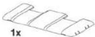

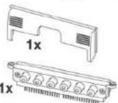
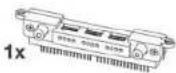


1x

42
SAFE SOUND

AUDISON AMPLIFIERS USED IN HIGH POWER AUDIO SYSTEMS CAN GENERATE EXTREMELY HIGH UNDISTORTED SOUND PRESSURE. REMEMBER THAT CONTINUOUS EXPOSURE TO EXCESSIVE SOUND PRESSURE LEVELS MAY PERMANENTLY DAMAGE YOUR HEARING. USE COMMON SENSE AND PRACTICE SAFE SOUND.
Safety must be your first priority while driving. Listening levels should never exceed the noise coming from your vehicle or from outside it, in order for you to promptly react to emergency situations.
We recommend that you carefully follow the instructions in this manual to get the best performance from your new amplifier. Building a high quality car audio system demands good automotive and electronic knowledge to avoid potential problems; if you feel you do not have the correct tools or expertise, please visit a specialized installer. A state-of-the-art installation will ensure a thrilling performance without affecting your safety or your automobile reliability.
This manual was written for offering information about the amplifier installation and use. Despite the huge amount of data and recommendations, there might not be the exact mounting instructions you need for your car. If, after reading it, you still have questions regarding this product, go and see your AUDISON dealer.
In case you need more information, you can contact Audison after sales service by email at the following addresses;
In Italy – supporto.tecnico@elettromedia.it International – support@elettromedia.it
43
LRx
The Universal Sound
audison
LRx 2.4
LRx 2.9
Owner's manual
General Precautions
- This symbol indicates that you have to pay attention to these instructions. Disregarding them might cause accidental harms or damage your amplifier.
- Before installing the amplifier, make sure you carefully read and understand all instructions.
- The vehicle electric system must have 12 VDC voltage with negative to ground. Make sure your car has it in order to avoid any damages to your amplifier and to the vehicle.
- Pre-plan the configuration of your new amplifier and the best wiring routes to ease installation.
• Always wear protective eyewear when using tools that may generate splinters.
- During installation, keep the amplifier in its packing as long as possible; this will protect it from damages.
- Secure all auxiliary devices you built to install the components to the vehicle structure through brackets, screws, nuts and bolts; this insures stability and safety while driving.
- The amplifier detachment while driving can damage the people in the vehicle and other cars. Secure the amplifier at best, paying utmost attention if installation is inside the passenger's compartment. Use extra fixing systems if installation occurs inside the engine compartment.
- Before installing the amplifier, turn off the source and all other electronic devices in the audio system for preventing any damages.
- Make sure the location you chose for the components does not affect the correct functioning of the vehicle mechanic and electric devices.
- Do not run the cables or install the amplifier next to electronic gearcases.
- Use extreme caution when cutting or drilling the car plate, checking there are no electrical wiring or structural element underneath.
- Before connecting the power cable to the amplifier, disconnect the negative lead (-) from the car battery.
- Make sure power cable is not short circuited during installation and connection.
- Power cable must have mechanically resistant and self-extinguishing insulation. Its section has to comply with what is suggested in this manual. Avoid to run it over or through sharp edges or close to moving mechanical devices. Make sure it is well fixed all along its length. Block positive and negative cables just close to the amplifier respective power supply terminal blocks through a clamping screw.
- Use rubber grommets to protect the wire if it runs in a hole of the plate or proper materials if it is close to heat-generating parts.
- To ground the device (-) in the right way, use a screw in the vehicle chassis; scrape all paint or grease from the metal if necessary; checking with a tester that there is continuity between the battery negative terminal (-) and the fixing point. If possible, connect all components to the same ground point; this solution rejects most noise.

- Route all signal cables close together and away from power cables.
- Never run cables outside the vehicle; you would not be protected against wear and in case of accidents.
- When installing speakers and the cables that connect them, make sure that non-insulated parts never touch the vehicle cutting parts. If they do, the amplifier protection is activated.
• To prevent all problems, use very good quality cables, connectors and accessories, choosing them in CONNECTION Audison catalogue.
- When installation is over, and before plugging the main power supply fuse, check the system wiring and make sure all connections were done in the right way.
- Power amplifiers put an increased load on the battery and on its charging system. We recommend checking your alternator and battery condition to ensure they can handle the increased consumption. Standard electrical systems which are in good condition should be able to stand this extra load without problems but we recommend the use of an energy storage capacitor and/or a battery for high level audio systems.
- Put a fuse and its insulated fuse holder 40 cm max. far from the battery positive terminal; connect one end of the power cable to it after connecting the other end to the amplifier. The fuse value must be 50% higher than the amplifier built-in one. In case the cable supplies several amplifiers, the fuse value will have to be 50% higher than the sum of the values of all other fuses in the amplifiers.
- There must be good air circulation where the amplifier is installed; this area must not be affected by humidity, rain, external deposits or parts coming from the vehicle mechanical devices. Don't cover ducts for forced cooling.
• Install the amplifier in the vehicle parts where temperature is between 0° C ( 32° F) and 55° C ( 131° F).
WARNING. When working in demanding conditions, the amplifier can reach temperatures of around 80 - 90°C (176÷194°F). Make sure it is not dangerously hot before touching it.
- Periodically clean the amplifier without using aggressive solvents that might damage it. Dampen a piece of cloth with water and soap, wring it and clean the amplifier. Then use a piece of cloth dampened with water only; eventually clean the amplifier with a dry piece of cloth.
- Remove dust and solid deposits from the ducts where air goes in and out. Don't use compressed air on the grilles without removing them, since it would push solid parts in the amplifiers. If necessary, please contact a specialised service centre for internal cleaning. Air ducts obstruction makes the amplifier go in safety.
ECI - Easy Common Interface Modules
The LRx amplifier input section is totally new. Audison created ECI, an interchangeable interface module that is very easy to use. There are two different modules and you can choose what type of signal input to use to drive the amplifier. These modules are also reversible, enabling you to run the input cables underneath the amplifier through special recesses in the amplifiers bottom plate. Special cable guide clips are provided to fix the cables. This is very useful for tight installation spaces where you do not have the room to have cables protruding past the amplifier chassis. A label indicates the correct layout and function.
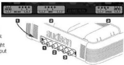
■ ECI - L Low Level: Pre-amplified Input/Output module
1_PRE OUT: Right and Left preamplified outputs. This output signal is filtered by PRE OUT control section;
2_ INPUT: Left and Right preamplified inputs for driving left and right channels;
3_PRE OUT - BYPASS: Left and Right preamplified outputs. Non-filtered output of the input signals.
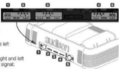
■ ECI - H High Level: High Level Input/PRE Output module
1_ Left PRE OUT: Left preamplified output. Non-filtered output of left speaker input signal;
2_OUT BYPASS (Speaker level): Right and left output of left and right speaker input signal;
3. Speaker INPUT: High level signals left and right inputs;
4_OUT BYPASS (Speaker level): Right and left output of left and right speaker input signal;
5. Right PRE OUT: Right preamplified output. Non-filtered output of right speaker input signal.
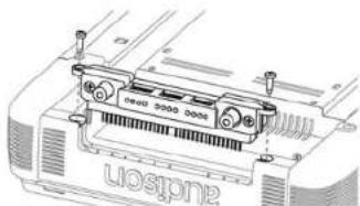
■ ECI module installation
Instructions are the same for both panels;

ECI-L Easy Common Interface - Low Level
■ ECI-H Easy Common Interface - High Level
- Remove the screws indicated in the drawing:
- Remove the module by pulling it up, paying special attention not to bend the contacts which are perpendicular to the amplifier:
- Replace the module with the one you want to use, or turn it with the contacts facing the amplifier inside, in the direction you choose;
- Mount the module paying attention to the contacts;
5_ Insert the module until it is all the way into its socket; - Fasten the screws making sure you don't force them.
■ When mounting ECI in reverse
A label is placed under the amplifier, near the input module, indicating the correct connections and configurations.
LRx
The Universal Sound
audison
LRx 2.4
LRx 2.9
Owner's manual
Power supply/Outputs/Other functions Panel
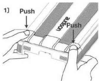
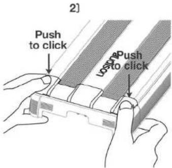
The panel with the power supply and speaker terminas is protected by a removable cover and end plate.
■ How to remove the cover
![2] Uosdme Pull](/content/2026/05/766812/images/769be9c3fc276f346306ade5a615f63d8acc4dd5c62ac985cfd054a543b5b84f.jpg)
■ How to reassemble the cover

48
■ How to change the plate
Two plates are supplied with the amplifier. One is formed for exposed cable routing; the other, with the Audison logo, is closed for protecting and hiding the cables. When you need
to reassemble the plate, match the tongue in pict. A and the location in pict. B.
to reassemble the plate, match the tongue in pict. A and the location in pict. B.
to reassemble the plate, match the tongue in pict. A and the location in pict. B.
to reassemble the plate, match the tongue in pict. A and the location in pict. B.
to reassemble the plate, match the tongue in pict. A and the location in pict. B.
![B] Note](/content/2026/05/766812/images/8ff782adbd9e5ae02b44d02305c91690ba013540cdcee7fa1ee154f101ae7877.jpg)
![Note A]](/content/2026/05/766812/images/ed90c1618cd5ad973ce090f9167a9d09199b049442af07d6e88c6717ec0db978.jpg)
■ Examples of how to use the plates
Power supply terminals are designed in order to allow mounting also with closed plate. A special milling on the terminal enables the cable jacket to bend naturally.
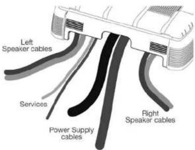
If the amplifier is fixed to a panel, the given template tells you where to drill holes for running the cables.

49
LRx
The Universal Sound
audison
Owner's manual
LRx 2.4
LRx 2.9
■ Power Supply and output terminal description
- Protection fuse: 40 A (LRx 2.4) / 60 A (LRx 2.9);
2_Anti-short circuit protective shield;
3_- Power (Ground): terminal block for
the amplifier power supply negative pole connection. Insert the battery
negative cable or a wire connected to the vehicle chassis here. The hole accepts cables up to
2 A.W.G. For the best current transfer,
we recommend the use of cables with as big a section as possible or,
at least, with the same section
as the wire connected to the positive pole;
4_ + Power (11÷15 VDC): terminal block for
the amplifier power supply positive pole connection.
Insert the battery positive cable here. The hole accepts cables
up to 2 A.W.G. For the best current transfer, we recommend the use of cables with as big a section as possible or, at least, with the same section as the wire connected to the negative pole;
- Left Speaker Out: Left Speaker + and - power terminal;
6_ Right Speaker Out: Right Speaker + and - power terminal; - Remote Sub Volume: Inputs for sub volume remote control, optional VCRA:
- Speaker ON: Inputs for turning on the amplifier through the speaker power cable.
If source does not have a 12 VDC Remote output, connect any power output, even in parallel with a factory speaker, here for turning on the amplifier; - Remote IN/OUT: REM IN, terminal for the Remote cable coming from the device which turns on the amplifier. Voltage must be between 7 and 16 VDC. REM OUT, terminal for repeating Remote voltage and turning on other electronic devices. Output voltage is
12 VDC at 50 mA. Connection made to the SPK ON, also without the REM IN, will supply voltage to the REM OUT to turn on other devices.

■ How to mount fast-on taker connectors
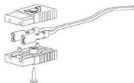
■ Other functions


![graph TD A["Speaker"] -->|Amp ON| B["Amplifier"] B --> C["ON"] B --> D["ON"] B --> E["ON"] C --> F["Output Signal"] D --> G["Output Signal"] E --> H["Output Signal"]](/content/2026/05/766812/images/67411518a5e5ff71ee36add9cb0f0eac55ab2f17ffea830542bb21499bd54d32.jpg)
![graph TD A["Speaker ON"] --> B["AMP OFF"] B --> C["Output Stage"] C --> D["Audio Input"] D --> E["Audio Output"] style A fill:#f9f,stroke:#333 style B fill:#ccf,stroke:#333 style C fill:#cfc,stroke:#333 style D fill:#fcc,stroke:#333 style E fill:#ffc,stroke:#333](/content/2026/05/766812/images/af412b6ab50a2942374e668e3f5a5d1adb42c5211c659ec378fe5ba4b91e6087.jpg)

52
Control panel
The panel which contains the amplifier controls is protected by a removable cover.
■ How to remove the cover
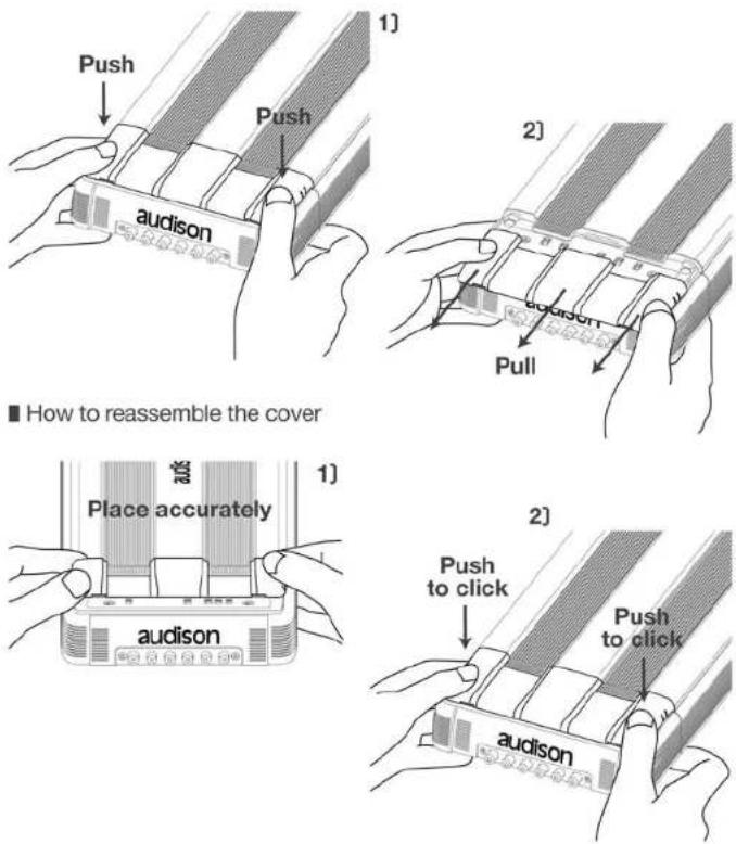
53
LRx
The Universal Sound
audison
LRx 2.4
LRx 2.9
Owner's manual
■ LRx 2.4 and LRx 2.9 functions
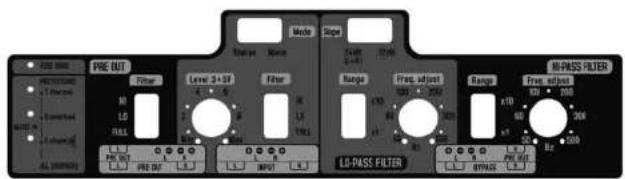
■ LRx 2.4 and LRx 2.9 control panel
■ Out Mode

![graph LR A["Filtered PRE OUT"] --> B["BYPASS, HI-PASS OR LO-PASS 12 dB FILTER"] C["INPUT L&R"] --> B D["OUT BYPASS"] --> B B --> E["Right Speaker"] B --> F["Left Speaker"] E --> G["Mono L + R"] F --> G](/content/2026/05/766812/images/af2c97a57b9f73c5f2d9747edb602b69e9455986f3a19a6fa47f9aa2eed95437.jpg)
![graph LR A["Filtered PRE OUT"] --> B["BYPASS, HI-PASS OR LO-PASS 24 dB FILTER"] C["INPUT L4R"] --> B D["OUT BYPASS"] --> B B --> E["Mono L + R"] B --> F["Mono L + R"] E --> G["Mono L + R"] F --> G](/content/2026/05/766812/images/5f557c53224e180543d791765fb45895be848548f2ceeee040f136266f6baa25.jpg)
54
![graph LR A["Filtered PRE OUT"] --> B["PRE OUT FILTER"] C["INPUT R"] --> B D["OUT BYPASS"] --> B B --> E["BYPASS, HI-PASS OR LO-PASS FILTER"] E --> F["Mono L + R"] F --> G["Mono Mode"]](/content/2026/05/766812/images/1932d9d7cd1eced138c54d37320356f92d04a808cdd8488f8145f2e550d9737c.jpg)
Level 0.3÷5 V
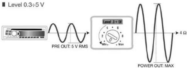
Adjust the input sensitivity control, tuning the amplifier input section according to the signal which comes from the source; this exploits the amplifier maximum power without distortion.
![graph LR A["Pre OUT: 5 V RMS"] --> B["Level 3 + 5V"] B --> C["Max 8 Min 6 Min 4"] C --> D["Distortion: 4 Ω"]](/content/2026/05/766812/images/e248a7bf89e50b1f6f68a1ce53438ee7effee698aeb935fbc81c06ffa6883bae.jpg)
55
LRx
The Universal Sound
audison
LRx 2.4
LRx 2.9
Owner's manual
Filter
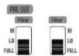
LRx stereo amplifiers have a flexible, independent filter section.
After choosing the amplifier power output configuration, you can easily select the signal to the PRE output.
Config. 1, 2, 3
AMP FULL
Config. 1, 4, 7
PRE OUT FULL

AMP HI 12 dB
Config. 4, 5, 6
PRE OUT HI 12 dB
Config. 2, 5, 8




56
AMP LO 12 dB
Config. 7, 8, 9
PRE OUT LO 12 dB
Config. 3, 6, 9
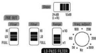
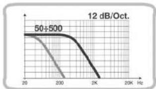


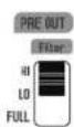
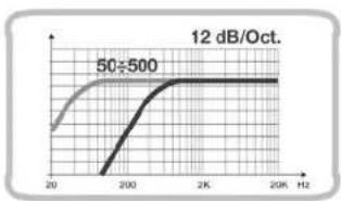
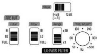
If the Filter control is switched to FULL, the amplifier power output is not filtered. If HI is selected, a 12 dB/Oct hi-pass filter is applied. When LO mode is selected, you can choose whether to cut the lo-pass signal at 12 dB/Oct. or at 24 dB/Oct. These settings are also for the PRE OUT output, which can be adjusted independently from the amplified section. If you configure the AMP and PRE OUT sections in the same way, either HI or LO, the same cut-off frequency will be applied to both, since it is handled by the same filter.
57
LRx
The Universal Sound
audison
LRx 2.4
LRx 2.9
Owner's manual
AMP LO 24 dB
Config. 7, 8, 9
PRE OUT LO 24 dB
■ Config. 3, 6, 9
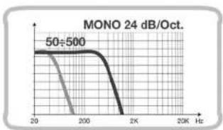
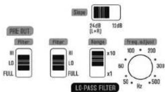
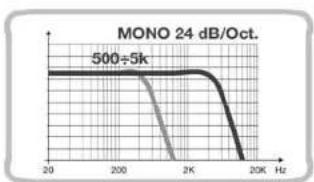
If you connect the stereo inputs and set the filter section to 24 dB (L+R), there will be a mono signal on both speaker power outputs terminals, the sum of the L + R signal inputs. We recommend the combined load connected to these terminals not to be lower than 4 Ohms. A mono signal, the sum of L + R signal inputs, will be directed to the PRE OUT and BYPASS outputs. Signals from left and right connectors will be the same.
■ Diagnostic LED description


■ Diagnostic LED description
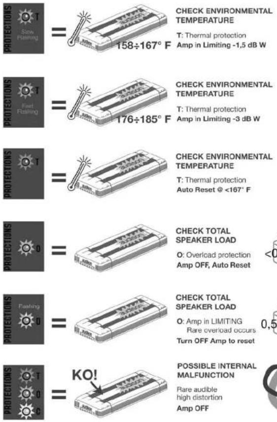
T: Thermal protection
Amp in Limiting -1,5 dB W
T: Thermal protection
Amp in Limiting -3 dB W
T: Thermal protection
Auto Reset @ <167°F
O: Overload protection Amp OFF, Auto Reset

O: Amp in LIMITING
Rare overload occurs
Turn OFF Amp to reset

Rare audible high distortion Amp OFF

Installation
■ Amplifier fixing
For hidden installation the mounting holes for the screws are inside the amplifier outline. Secure the screws with the extended length screw driver bit provided with the amplifier.

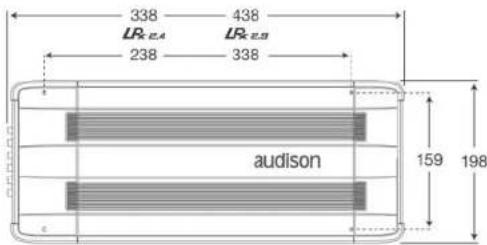
LRx
The Universal Sound
audison
Owner's manual
LRx 2.4
LRx 2.9
■ Mounting template
![graph TD A["Service: Power Supply Cable Hole Area"] --> B["Perimetro per il montaggio a fio del parinello Non-Projecting Outline"] A --> C["Perimetro per il montaggio semi-incassato Semi-Projecting Outline"] A --> D["Perimetro esterno External Outline"] E["Speaker Cable Hole Area"] --> F["Fori di fi…](/content/2026/05/766812/images/350ae9ff78626ec069c12355d80cd5eaf45dc9fd2272821c6026f0780c8cbafe.jpg)
A template is supplied to help you pre-plan the mounting of your amplifier. Printed on the template are instructions for flush or semi-embedded mounting, or for installing it on a flat surface. If you want to hide the cables, you can refer to the proper holes on the template.
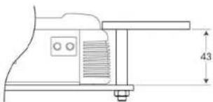
■ Flush mounting
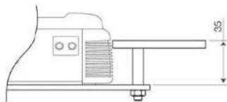
■ Semi-embedded mounting

62
You can connect the cables to ECI-H module before securing it to the amplifier. Choose the module position and follow the connection instructions you can find on the labels. The amplifier must be off.

■ How to run the cables under the amplifier
If you use CONNECTION Audison interconnects, attach Y BLOCK on one of the mounting pins of the amplifier after plugging in RCA connectors.
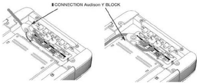
Route the cable in the proper location and secure it with the supplied clips.
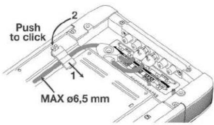
To attach the clip, insert the tongue first, and then press until you hear a click.
63
■ Audison logo in reverse


LRx
The Universal Sound
audison
LRx 2.4
LRx 2.9
Owner's manual
Connection cables
For maximum performance, always use new, good quality cables; their outer jacket must not be spoiled, and the copper must not show oxidation. For proper operation, always consider the length of the connection, the load and the current it has to handle. CONNECTION Audison products are the most flexible and complete; they are designed and built in order to get the best out of every installation, especially when used with Audison amplifiers.
■ Speaker Cable
The table refers to continuous power into 4 Ohm load. If load decreases, cable size will have to increase proportionally.
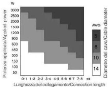
■ Power supply cable
If you don't know your system current consumption, find it using the mathematical formula below and find this same value on the left hand column of the table. Then calculate the length of your connection and find this same value on the bottom column of the table. At the point where these two values cross is the minimum section in gauge (A.W.G.) which CONNECTION recommends for building a high performance, reliable system.
How to calculate your system current consumption
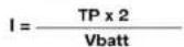
I = Current consumption of your system in ampere (A);
TP = Total power (RMS) of all channels of all amplifiers in your system;
Vbatt = Usually value is 12 V, the nominal automotive electrical system voltage.
Example:
- Your total system power (RMS) of all channels in all amplifiers is a combined 650 W.
- Your amplifier average 50% efficiency, as most amplifiers today.
- Your electrical system is 12 Volt.
I = 650 × 2/12 = 108.3 A Current consumption

66
Pattern

Power Cable Ground Cable Speaker Cable
Subwoofer Cable Audio Interconnect Video Interconnect
1 BATTERY CLAMPS: ensure high current transfer without the power robbing consequences of a high resistance connection.
2 GROUND TERMINALS: minimizing resistance and the consequent power losses associated with poor system grounding.
3 FUSE HOLDERS: are the first line of protection for your vehicle and yourself from dangerous short circuits. The high temperature case and waterproof construction ensure reliability in any environmental condition.
4 POWER & GROUND CABLES: are of fundamental importance to obtain reference performance in your car audio/video system. The special structure of Main Power and Power Flow cables minimize eddy current power losses and allow high instantaneous current transfer, enabling you to experience the full dynamics of your music.
5 FUSE DISTRIBUTION: their name tells you their function: transferring energy to electronic devices. They are available in various models, even modular, and they can house the protection fuse. Fuse distributions are to be used in every system where you need to transfer a huge amount of current without losses.
6 GROUND DISTRIBUTION BLOCKS: are as important as the power distribution to your systems overall performance. Solid, low resistance ground points prevent harmful voltage differences between components and improve high-level current transfer without power loss.
7 SUPERFARAD™: capacitors act as a "current reserve" storing DC energy for when your amplifiers demand it the most.
8 AUDIO INTERCONNECTS: are the first component in your system that audio signals pass through. For faithful reproduction, they must transfer these signals from the head-unit to the amplifiers without modifying the sound, while at the same time, reject the tremendous amount of noise radiated by on-board computer-controlled devices in your automobile.
VIDEO INTERCONNECTS: provide outstanding picture detail, definition and color balance. With constant 75-ohm impedance and outstanding shielding, stunning picture quality is assured.
10 SPEAKER CABLES: provide that last step in the faithful reproduction of your music. They ensure the transfer of music to your speakers without the coloration or degradation of the signal.
67
Configuration
■ LRx 2.4 and LRx 2.9
For setting the control panel switches properly, refer to the diagrams in the Filter section, starting on page 53.
■ Filters configuration
You can independently select a bypass, hi-pass or lo-pass filter to be applied to the amplifier and to PRE OUT output. If the amplifier and the PRE OUT output are configured in the same way, both will output the same signal and cut-off frequency selected.
■ Input/Output configuration
In stereo mode: When INPUT is stereo, and HI-PASS and/or LO-PASS filter is set to 12 dB, a stereo filtered signal will be directed to the PRE OUT outputs and to the amplified outputs. When the filter is set to LO-PASS 24 dB, a lo-pass mono filtered signal is directed to the PRE OUT outputs and to the amplified outputs, the sum of the L + R signal inputs.
In mono mode, only the right input is activated. You will have a mono signal in PRE OUT and in amplified outputs with whatever types of selected filter. Only the right BYPASS output connector will have the same signal as the right channel input.
| Config. | AMP | PRE OUT |
| 1 | ||
| 2 | ||
| 3 | ||
| 4 | ||
| 5 | ||
| 6 | ||
| 7 | ||
| 8 | ||
| 9 |
| INPUT | FILTER | PRE OUT | BYPASS | AMP | ||
| Stereo | Mono | L & R | HI/LO-PASS12 dB | L & RFiltered | L & RBypass | L & RFiltered |
| Mono | L & R | LO-PASS24 dB | L + RFiltered | L + RBypass | L + RFiltered | |
| Mono | Mono | R | HI/LO-PASS12/24 dB | RFiltered | RBypass | MonoFiltered |
68
■ 2 way mono-amplified
![graph TD A["Input (ECI-L or ECI-H) FRONT"] --> B["PRE OUT Optional use"] B --> C["Left"] B --> D["Right"] E["FRONT LEFT"] --> F["Ground"] G["FRONT RIGHT"] --> H["Ground"]](/content/2026/05/766812/images/0c237f7251000fd8bcabe94e58fc1810c9facc25c3b942840649d17a33623272.jpg)
■ 2 way + Sub tri-mode
![graph TD A["Input (ECI-L or ECI-H) FRONT"] --> B["FRONT LEFT"] A --> C["PRE OUT Optional use"] A --> D["FRONT RIGHT"] B --> E["Left"] C --> F["Right"] D --> G["Sub MONO"] style A fill:#f9f,stroke:#333 style B fill:#ccf,stroke:#333 style C fill:#cfc,stroke:#333 style D fill:#fcc,stroke:#333 style E f…](/content/2026/05/766812/images/dcf0b78c2e83126c83a1eb9948cade08ae8c43f3de4be63ecf994f7fd7fcac12.jpg)
69
![graph TD A["INPUT (ECI-L or ECI-H) FRONT"] --> B["FRONT LEFT"] B --> C["LEFT"] C --> D["PRE OUT"] D --> E["Optional use"] E --> F["LR_2.4"] E --> G["LR_2.9"] H["INPUT (ECI-L or ECI-H) Stereo"] --> I["FRONT RIGHT"] I --> J["Left"] J --> K["Right"] K --> L["HI-PASS PRE OUT"] L --> M["SUB"]](/content/2026/05/766812/images/94307b7666bc46f2ac4fc4ef9e493a13a71b408655ff3e05c6f1ae167447058c.jpg)
![graph TD A["FRONT"] --> B["INPUT (ECI-L or ECI-H) FRONT"] B --> C["PRE OUT"] C --> D["LR2.8"] D --> E["LEFT"] E --> F["RIGHT"] F --> G["PRE OUT Optional use"] G --> H["LR2.4"] H --> I["B Left"] I --> J["SUB"] J --> K["LR2.1K"] K --> L["INPUT (ECI-L or ECI-H) Stereo"] M["FRONT"] --> N["INPUT (ECI-L o…](/content/2026/05/766812/images/37ce1a774120f88a44494bddfc7e3f96cc2ccbd17a608121af768b45c82cc58a.jpg)
70
■ 3 way multi-amplified + Sub
![graph TD A["INPUT (ECI-L or ECI-H) FRONT"] --> B["MID-HIGH LEFT"] A --> C["MID-HIGH RIGHT"] B --> D["PRE OUT Optional use LR_2.4"] C --> E["PRE OUT Optional use LR_2.8"] D --> F["Left"] E --> G["Right"] H["WOOFER LEFT"] --> I["Parallel Connection 2 Ω"] I --> J["INPUT (ECI-L or ECI-H) REAR"] J --> K[…](/content/2026/05/766812/images/bed7aff89b16bcbf9407b0ea1e8187397bef03bf1b858e5c04ec1ec56d88b110.jpg)
71
■ 3 way active Front multi-amplified + Rear + Sub
![graph TD A["IN A Ch (ECI-L or ECI-H) MID-HIGH"] --> B["PRE OUT Optional use LR4.5 OUT MODE 4 Ch"] C["MID-HIGH LEFT"] --> D["A Left"] E["MID-HIGH RIGHT"] --> F["B Right"] G["INPUT (ECI-L or ECI-H)"] --> H["WOOFER"] I["WOOFER LEFT"] --> J["Parallel Connection 2 Ω"] K["WOOFER RIGHT"] --> L["Parallel Co…](/content/2026/05/766812/images/cdf8451fab1dd9a0c9ef2c1046791eeb077de09891ef99ef91ddf93b239fcade.jpg)
72
■ Active multi-amplification: Front 3 way + Rear 2 way + Sub
![graph TD subgraph Left_Side FRONT1["TWEETER LEFT"] --> INPUT1["INPUT PRE OUT"] FRONT2["MIDRANGE LEFT"] --> INPUT1 FRONT3["PROVINC"] --> INPUT1 FRONT4["PROVINC"] --> INPUT1 FRONT5["PROVINC"] --> INPUT1 FRONT6["PROVINC"] --> INPUT1 FRONT7["PROVINC"] --> INPUT1 FRONT8["PROVINC"] --> INPUT1 FRONT9["PROV…](/content/2026/05/766812/images/808aba3bf42485ccfcf3aa59b90e19436ef16775edf1f65ab6c867c75c3c211f.jpg)
73
Technical specifications
| LR×2.4 | LR×2.9 | |
| Power supply | ||
| Voltage | 11÷15 VDC | 11÷15 VDC |
| Minimum idling current | 1.3 A | 1.7 A |
| Idling current when off | 0.02 mA | 0.02 mA |
| Consumption @ 14.4 VDC(MAX musical power) | 36 A | 65 A |
| Remote IN Voltage | 7÷15 VDC (1 mA) | 7÷15 VDC (1 mA) |
| Remote OUT Voltage | 12 VDC (50 mA) | 12 VDC (50 mA) |
| Internal fuse (AFS) | 40 A | 60 A |
| Amplifier stage | ||
| Distortion - THD (1 kHz @ 4 Ω) | 0.04% | 0.04% |
| Bandwidth (-3 dB) | 4÷80k Hz | 4÷80k Hz |
| S/N ratio (A weighted @ 1 V) | 100 dB | 100 dB |
| Damping factor (1 kHz @ 4 Ω) | 120 | 120 |
| Input sensitivity (PRE IN) | 0.3÷5 V | 0.3÷5 V |
| Input sensitivity (Speaker IN) | 1.4÷24 V | 1.4÷24 V |
| Input impedance (PRE IN) | 15 kΩ | 15 kΩ |
| Input impedance (Speaker IN) | 5 kΩ | 5 kΩ |
| Load impedance (MIN) | ||
| • 2 Ch | 2x2 Ω | 2x2 Ω |
| • 1 Ch | 1x4 Ω | 1x4 Ω |
| Nominal output power(RMS) PN @ 12 VDC; THD 0.3% | 120 W x 2 Ch | 210 W x 2 Ch |
| Output power (RMS) @ 14.4 VDC; THD 1% | ||
| • Stereo 2 Ch x 4 Ω | 130 W x 2 | 260 W x 2 |
| • Stereo 2 Ch x 2 Ω | 230 W x 2 | 450 W x 2 |
| • Mono 1 Ch x 4 Ω | 460 W x 1 | 900 W x 1 |
| Inputs / Outputs / Filters | ||
| Mode | Mono / Stereo | Mono / Stereo |
| Input | PRE / Speaker | PRE / Speaker |
| OUT (Filtered) | PRE | PRE |
| OUT (Bypass) | PRE / Speaker | PRE / Speaker |
| Filter | Bypass / Hi-pass / Lo-pass 50 ÷ 5k Hz @ 12 / 24(mono) dB/Oct. | |
| PRE OUT Filter | Bypass / Hi-pass / Lo-pass 50 ÷ 5k Hz @ 12 / 24(mono) dB/Oct. | |
| Sub remote volume control | + 5 ÷ -5 dB Active with Lo-pass 24 dB L+R | |
| Size | ||
| B x L x H inches | 7"13/16 x 13"5/16 x 2"1/4 | 7"13/16 x 17"1/4 x 2"1/4 |
| Weight to | 7.0 | 9.5 |
![graph TD A["PRE OUT"] --> B["L"] C["R"] --> D["12 dB/Oct"] E["PRE IN"] --> F["L"] G["R"] --> H["N"] I["PRE OUT FULL"] --> J["L"] K["R"] --> L["N"] M["VCA"] --> N["Lo-pass 2.0V"] O["Level Signal"] --> P["Waveform 1-2"] Q["Filter Signal"] --> R["Waveform 3-4"] S["Sligo Signal"] --> T["Waveform 5-6"] U…](/content/2026/05/766812/images/12b6d21312cb1ca441985ebc3b07667cbfb957a831ba0975c5c4ad8e62f74193.jpg)
- INTRODUZIONE
- INDICE
- CONTENUTO DELL'IMBALLO
- SAFE SOUND
- PRECAUZIONI GENERALI
- PANNELLO INGRESSI ECI - EASY COMMON INTERFACE
- ECI - L LOW LEVEL: PANNELLO INGRESSI PREAMPLIFICATI
- ECI - H HIGH LEVEL: PANNELLO INGRESSI ALTO LIVELLO/USCITE PRE
- INSTALLAZIONE DEI PANNELLI INGRESSI ECI
- QUANDO SI MONTA L'ECI ROVESCIATO
- PANNELLO ALIMENTAZIONE/USCITE/SERVIZI
- COME CAMBIARE LA MASCHERINA
- ESEMPI DI UTILIZZO DELLE MASCHERINE
- DESCRIZIONE
- COME SI MONTANO I CONNETTORI PORTAFASTON
- COME SI SOSTITUISCE IL FUSIBILE
- PANNELLO CONTROLLI
- FILTER
- PROTECTION LEDS
- INSTALLAZIONE
- FISSAGGIO DELL'AMPLIFICATORE
- COME FAR PASSARE I CAVI DI SEGNALE SOTTO L'AMPLIFICATORE
- LRX
- CAVI DI CONNESSIONE
- POTENZA
- ALIMENTAZIONE
- CONFIGURAZIONI
- LRX 2.4 E LRX 2.9
- CONFIGURAZIONE DEI FILTRI
- CONFIGURAZIONE DEGLI INGRESSI/USCITE
- INTRODUCTION
- TABLE OF CONTENTS
- PACKING CONTENTS
- GENERAL PRECAUTIONS
- ECI - EASY COMMON INTERFACE MODULES
- ECI - L LOW LEVEL: PRE-AMPLIFIED INPUT/OUTPUT MODULE
- ECI - H HIGH LEVEL: HIGH LEVEL INPUT/PRE OUTPUT MODULE
- ECI MODULE INSTALLATION
- WHEN MOUNTING ECI IN REVERSE
- POWER SUPPLY/OUTPUTS/OTHER FUNCTIONS PANEL
- HOW TO CHANGE THE PLATE
- EXAMPLES OF HOW TO USE THE PLATES
- POWER SUPPLY AND OUTPUT TERMINAL DESCRIPTION
- HOW TO MOUNT FAST-ON TAKER CONNECTORS
- CONTROL PANEL
- INSTALLATION
- AMPLIFIER FIXING
- HOW TO RUN THE CABLES UNDER THE AMPLIFIER
- CONNECTION CABLES
- SPEAKER CABLE
- POWER SUPPLY CABLE
- CONFIGURATION
- LRX 2.4 AND LRX 2.9
- FILTERS CONFIGURATION
- INPUT/OUTPUT CONFIGURATION
Marke : AUDISON
Modell : LRX 2.9
Kategorie : Autoradio