SE-A2000 - Empfänger TECHNICS - Kostenlose Bedienungsanleitung
Finden Sie kostenlos die Bedienungsanleitung des Geräts SE-A2000 TECHNICS als PDF.

Benutzerfragen zu SE-A2000 TECHNICS
0 Frage zu diesem Gerät. Beantworten Sie die, die Sie kennen, oder stellen Sie Ihre eigene.
Eine neue Frage zu diesem Gerät stellen
Laden Sie die Anleitung für Ihr Empfänger kostenlos im PDF-Format! Finden Sie Ihr Handbuch SE-A2000 - TECHNICS und nehmen Sie Ihr elektronisches Gerät wieder in die Hand. Auf dieser Seite sind alle Dokumente veröffentlicht, die für die Verwendung Ihres Geräts notwendig sind. SE-A2000 von der Marke TECHNICS.
BEDIENUNGSANLEITUNG SE-A2000 TECHNICS
Technics
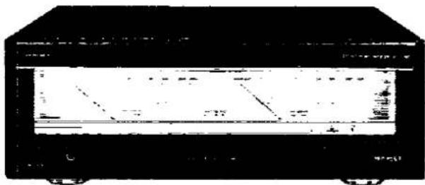
Stereo Power Amplifier
SE-A2000
Operating Instructions
natural_image
Front view of a black electronic device with visible circuit lines and ports (no readable text or symbols)Notes:
- Specifications differ according to the area code.
- The "EB" area code, for example, Indicates United Kingdom specifications.
• The "EB" indication is shown on the packing case.
Before connecting, operating or adjusting this product, please read these instructions completely.
EG EB G
RQT1988-B
Dear Customer
Thank you for purchasing this Technics product. For optimum performance and safety, please read these instructions carefully.
Contents
- Accessories 2
- Caution for AC mains lead (United Kingdom only) 3
- Connections 4
- Front Panel Controls and Functions ..... 6
• Operation....7
• Description of Technical Features ..... 8
• Technical Specifications 9
- Block Diagram 10
- Suggestions for Safety 11
- Troubleshooting Guide .... Back cover
- Maintenance .... Back cover
-For areas except United Kingdom and Europe.-
CAUTION:
The AC voltage is different according to the area. Be sure to set the proper voltage in your area before use. (For details, please refer to the page 5.)
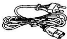
Accessories
- AC power supply cord .... 1
(For United Kingdom)
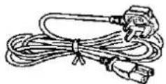
(For others)
• Power plug adaptor ....? (Not supplied for United Kingdom and Europe.)

Caution for AC mains lead
(United Kingdom only)
("EB" area code model only)
For your safety, please read the following text carefully.
This appliance is supplied with a moulded three pin mains plug for your safety and convenience.
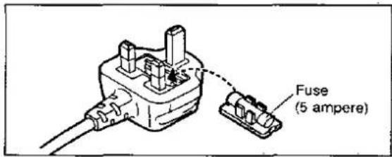
A 5-ampere fuse is fitted in this plug.
Should the fuse need to be replaced please ensure that the replacement fuse has a rating of 5-ampere and that it is approved by ASTA or BSI to BS1362. Check for the ASTA mark 🖱 or the BSI mark 🖼 on the body of the fuse.
If the plug contains a removable fuse cover you must ensure that it is refitted when the fuse is replaced.
If you lose the fuse cover the plug must not be used until a replacement cover is obtained.
A replacement fuse cover can be purchased from your local dealer.
CAUTION!
IF THE FITTED MOULDED PLUG IS UNSUITABLE FOR THE SOCKET OUTLET IN YOUR HOME THEN THE FUSE SHOULD BE REMOVED AND THE PLUG CUT OFF AND DISPOSED OF SAFELY.
THERE IS A DANGER OF SEVERE ELECTRICAL SHOCK IF THE CUT OFF PLUG IS INSERTED INTO ANY 13-AMPERE SOCKET.
If a new plug is to be fitted please observe the wiring code as shown below.
If in any doubt please consult a qualified electrician.
IMPORTANT
The wires in this mains lead are coloured in accordance with the following code:
Blue: Neutral
Brown: Live
As the colours of the wires in the mains lead of this appliance may not correspond with the coloured markings identifying the terminals in your plug, proceed as follows:
The wire which is coloured BLUE must be connected to the terminal in the plug which is marked with the letter N or coloured BLACK.
The wire which is coloured BROWN must be connected to the terminal in the plug which is marked with the letter L or coloured RED.
Under no circumstances should either of these wires be connected to the earth terminal of the three pin plug, marked with the letter E or the Earth Symbol 12 .
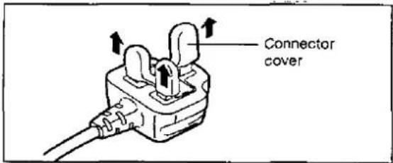
Before use
Remove the connector cover as follows.
How to replace the fuse
- Remove the fuse cover with a screwdriver.
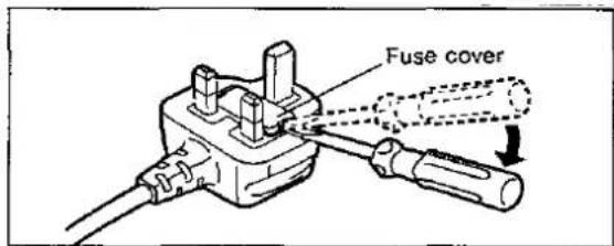
- Replace the fuse and attach the fuse cover.
Before making connections, be sure that the power to this unit and all other equipment is first turned off.
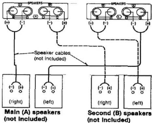
1 To connect speakers
One pair of speakers can be connected to the "A" terminals of this unit and one pair to the "B" terminals.
flowchart
graph TD
    A["Speaker 1"] --> B["Speaker Cable (not included)"]
    C["Speaker 2"] --> D["Speaker Cable (not included)"]
    E["Speaker 3"] --> F["Speaker Cable (not included)"]
    G["Speaker 4"] --> H["Speaker Cable (not included)"]
    I["Speaker 5"] --> J["Speaker Cable (not included)"]
    K["Speaker 6"] --> L["Speaker Cable (not included)"]
    M["Speaker 7"] --> N["Speaker Cable (not included)"]
    O["Speaker 8"] --> P["Speaker Cable (not included)"]
    Q["Speaker 9"] --> R["Speaker Cable (not included)"]
    S["Speaker 10"] --> T["Speaker Cable (not included)"]
    U["Speaker 11"] --> V["Speaker Cable (not included)"]
    W["Speaker 12"] --> X["Speaker Cable (not included)"]
    Y["Speaker 13"] --> Z["Speaker Cable (not included)"]
    AA["Speaker 14"] --> AB["Speaker Cable (not included)"]
    AC["Speaker 15"] --> AD["Speaker Cable (not included)"]
    AE["Speaker 16"] --> AF["Speaker Cable (not included)"]
    AG["Speaker 17"] --> AH["Speaker Cable (not included)"]
    AI["Speaker 18"] --> AJ["Speaker Cable (not included)"]
    AK["Speaker 19"] --> AL["Speaker Cable (not included)"]
    AM["Speaker 20"] --> AN["Speaker Cable (not included)"]
Note:
Be sure to only connect positive (+) wires to positive (+) terminals, and negative (−) wires to negative (−) terminals.
■ Speaker impedance
- When only the "A" or only the "B" terminals are used: 4–16 ohms
- When both the "A" and the "B" terminals are used simultaneously: 8–16 ohms
■ Connection of speaker wires
- Twist the center conductor.

- Turn the knob to the left and insert the wire.
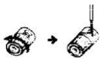
- Tighten the knob by turning it to the right and pull the wire to assure a proper connection.

To prevent damage to the circuitry, never short-circuit positive (+) and negative (−) speaker wires.

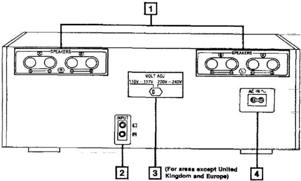
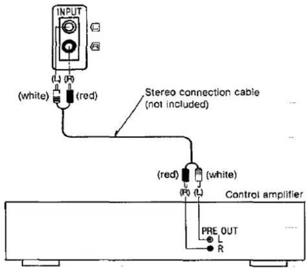
2 To connect to the control amplifier
Use a stereo connection cable (not included) to connect to the output terminals of the control amplifier.
3 To set the power voltage (For areas except United Kingdom and Europe)
Set the voltage selector to "110 V - 127 V" or "220 V - 240 V" according to the area in which the unit will be used. [Use a minus (−) screwdriver]
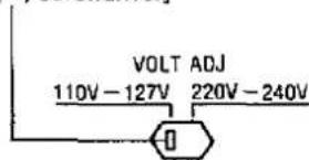
Note: Note that this unit will be seriously damaged if this setting is not made correctly.
4 To connect the AC power supply cord
United Kingdom only BE SURE TO READ THE CAUTION FOR THE AC MAINS LEAD ON PAGE 3 BEFORE MAKING THE FOLLOWING CONNECTION.
Connect the AC power supply cord (Included) after all other cables and cords are connected.
Note: The configuration of the AC power supply cord differs according to area.
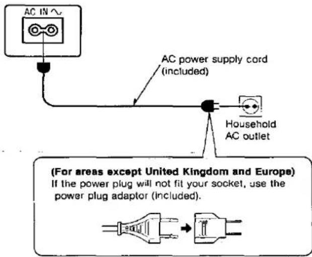
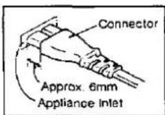
Insertion of Connector
Even when the connector is perfectly inserted, depending on the type of inlet used, the front part of the connector may jut out as shown in the drawing.
However there is no problem using the unit.
Caution:
Do not place books, etc., on top of this unit so that the heat radiation vents remain unblocked.
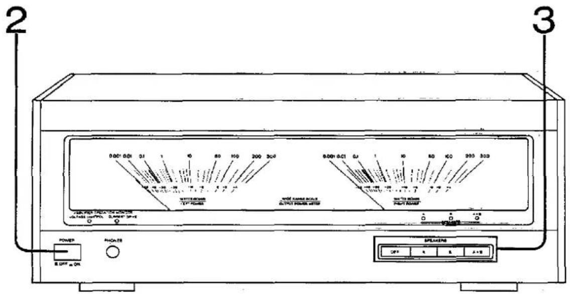
Front Panel Controls and Functions
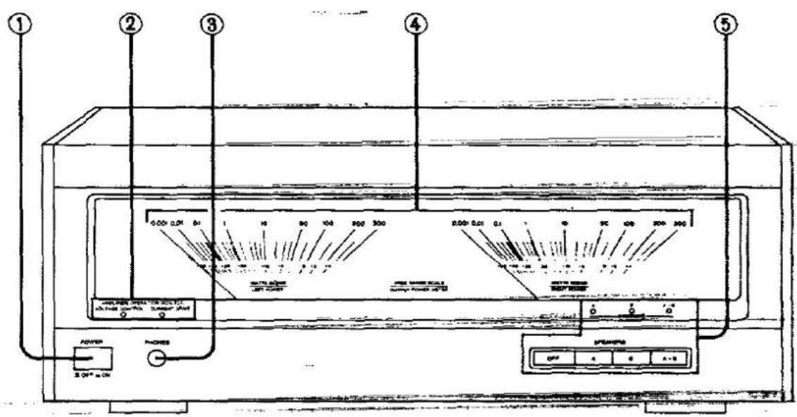
① Power switch (POWER)
② Operation indicators (AMPLIFIER OPERATION MONITOR)
These indicators illuminate to indicate the operating condition of this unit.
VOLTAGE CONTROL:
Illuminates up when the power is switched on. Indicates that the voltage control amplifier is ready to operate.
CURRENT DRIVE:
Illuminates approximately 3 seconds after the voltage control amplifier indicator illuminates. Indicates that the main unit is ready to operate.
If an abnormal condition in the circuitry is detected, such as DC voltage appearing in the output, or a short-circuit of the positive (+) and negative (−) wires from the speaker terminals, the protection circuit functions and this indicator will not illuminate.
③ Headphones jack (PHONES)
④ Power meters
Indicate the output (watts) of this unit.
When speakers having an impedance of 8 Ω are connected, the output level will be as indicated. However, if the speaker impedance is 16 Ω, the output level will be one-half the indicated value, and if the impedance is 4 Ω, the output level will be double the indicated value.
Actual output =
meter Indication × 8()impedance of the speakers ()
⑤ Speaker selectors/Indicators (SPEAKERS)
These selectors are used to select the speakers (A and/or B). OFF: No sound will be heard from the speakers.
A: Sound can be heard from the speakers connected to the "A" terminals.
B: Sound can be heard from the speakers connected to the "B" terminals.
A + B: Sound can be heard simultaneously from the speakers connected to the "A" terminals and the "B" terminals.
Operation
In order to protect the speakers, before performing the following procedure, set the volume on the control amplifier to the minimum position.
1 Switch on the power of the control amplifier.
2 Switch ON the power of this unit. (The operation Indicators will illuminate.)
3 Select the speakers to be used. (The corresponding speaker indicator will illuminate.)
4 Operate the tape deck, CD player, or other equipment and adjust the volume on the control amplifier.
NOTE:
Because this unit has a very high output level, if the permissible input of the speaker is only low, the speakers could become damaged. Therefore, watch the power meters while adjusting the volume on the control amplifier and do not exceed the permissible input of the speakers being used.
After listening is finished:
First switch off the power of this unit, and then switch off the power of the control amplifier.
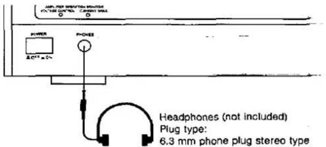
When listening through headphones
Connect the headphones to the headphones jack.
Always be sure to turn down the volume on the control amplifier before connecting the headphones.
If the sound from the speakers is not wanted, set the speaker selector to the "OFF" position.
Note:
Avoid listening for prolonged periods of time to prevent hearing damage.
Description of Technical Features
Newly developed "MOS class AA" circuit
Technics developed the Class AA circuit in 1985, and since that time it has been used in many amplifiers. With the conventional power amplifiers, a single amplifier was used to perform two functions: "amplify the voltage" and "drive the current to the speakers". The Class AA circuit is a totally new and unique concept which has succeeded in combining two separate amplifiers, each of which performs one specific function.
Great progress has recently been made in semiconductor mass production technology, and the MOS FET, said to be the ideal semiconductor amplifier component, has been improved for use in audio equipment. However, as a component for the output stage, the MOS FET still has its own strong points and weak points when compared with the conventional bipolar transistor. Thus, by extending and expanding the features of the Class AA circuit, which created a whole new concept for the relationship between an amplifier's voltage amplification and current amplification, Technics has now developed the new MOS Class AA circuit, which combines the strong points of both the bipolar transistor and the MOS FET.
Considering the special features of the MOS Class AA circuit from the circuitry aspect, it is comprised of an A class voltage control amplifier which performs overall control of the entire amplifier, and a B class amplifier which generates the current to drive the speakers, thus combining high-quality A class sound with the capability to drive any type of speaker. Furthermore, in order to make the most of the features of this circuitry composition, a MOS FET which has excellent input and output linearity is used for the voltage control amplifier, and a bipolar transistor which has outstanding drive capability is used for the current drive amplifier.
As a result, the sound data from the input source is faithfully reproduced without the addition of any unwanted noise.
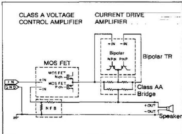
MOS Class AA circuit
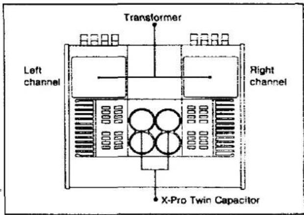
Twin-monaural composition with high-performance power supply units
This circuit features a twin-monaural composition in which the left channel and the right channel are independent of each other. As a result, noise generated by mutual interference between the two channels and the cross talk phenomenon have been drastically reduced.
The power supply section for each channel is equipped with a high-performance R-shaped core transformer having extremely low leakage flux. In addition, X-Pro twin capacitors are used for the electrolytic capacitors. In this composition, for each capacitor, there are two electrolytic capacitors, one for the (+) side and one for the (−) side, packed together with shock-absorbing material into a resin case with a copper cap, thus reducing both mechanical vibration and electromagnetic radiation.
Using this twin-monaural composition with its high-performance power supply units, it is possible to reproduce powerful superbass sounds and achieve excellent channel separation.
R-shaped core transformer with low leakage flux
Most transformers use an EI type core or a toroidal core. However, in either case the core's cross-section is square-shaped, so the magnetic flux induced by the coil is not uniform, but rather lopsided at certain parts. In contrast, this power amplifier is equipped with a transformer which has a core with an R-shaped cross-section, thus reducing leakage flux and preventing the entrance of unwanted noise.
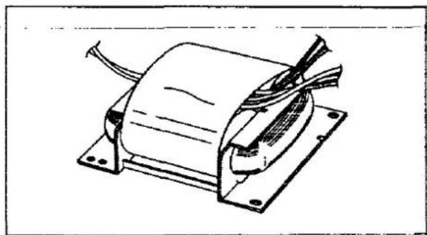
natural_image
Technical line drawing of an electric motor with coil and mounting base (no text or symbols)Other features
■ High-precision large-sized power meters
This model is equipped with the same large-sized power meters which have become a tradition on Technics power amplifiers. Furthermore, it is also equipped with operation indicators that confirm when the voltage control amplifier and the current drive amplifier are ready to operate and with speaker indicators.
Electronic speaker selectors
Electronic switches are used for the speaker selectors. Gold-clad contacts are used for the selector relays, thus providing light-touch operation and high reliability.
■ High-rigidity chassis
In order to provide solid support for the high-performance circuitry components, the cabinet features a completely vibration-proof design made possible by a high-rigidity chassis.
Technical Specifications (DIN 45 500)
20 Hz–20 kHz continuous power output both channels driven 2 × 100 W (8 Ω) 2 × 140 W (4 Ω)
1 kHz continuous power output both channels driven (THD: 1%) 2 × 110 W (8 Ω) 2 × 160 W (4 Ω)
63 Hz-12.5 kHz continuous power output both channels driven (THD: 0.7%) 2 × 10⁵ W (8 Ω) 2 × 145 W (4 Ω)
Total harmonic distortion rated power at 20 Hz–20 kHz 0.005% (8 Ω) 0.009% (4 Ω) half power at 20 Hz–20 kHz 0.003% (8 Ω)
Intermodulation distortion (50 Hz: 7 kHz = 4:1, SMPTE) rated power 0.005% (8.Ω)
Power bandwidth (both channel driven) -3 dB THD 0.05% 5 Hz - 80 kHz (8 Ω)
Residual hum and noise 0.15 mV Damping factor 100 (8 Ω) 50 (4 Ω)
Headphones output level/impedance 680 mV/330 Ω Load impedance
A or B 4 Ω–16 Ω A and B 8 Ω–16 Ω Input sensitivity/impedance 1.0 V/33 kΩ
S/N (rated power, 4 Ω) 107 dB (115 dB, IHF '66) Frequency response 0.8 Hz–150 kHz (+0, -3 dB) +0 dB, -0.2 dB (20 Hz–20 kHz)
GENERAL
Power consumption 380 W
Power supply For Europe AC 50 Hz/60 Hz, 230 V For United Kingdom AC 50 Hz/60 Hz, 230 V - 240 V For others AC 50 Hz/60 Hz, 110 V - 127 V/220 V - 240 V
Dimensions (W × H × D) 448 × 186 × 431 mm Weight 22 kg
Notes:
-
Specifications are subject to change without notice. Weight and dimensions are approximate.
-
Total harmonic distortion is measured by the digital spectrum analyzer.
-
For areas except Europe The specification values given have been measured while using a 240 V power supply.
(For United Kingdom)
This apparatus was produced to BS 800.
Block Diagram
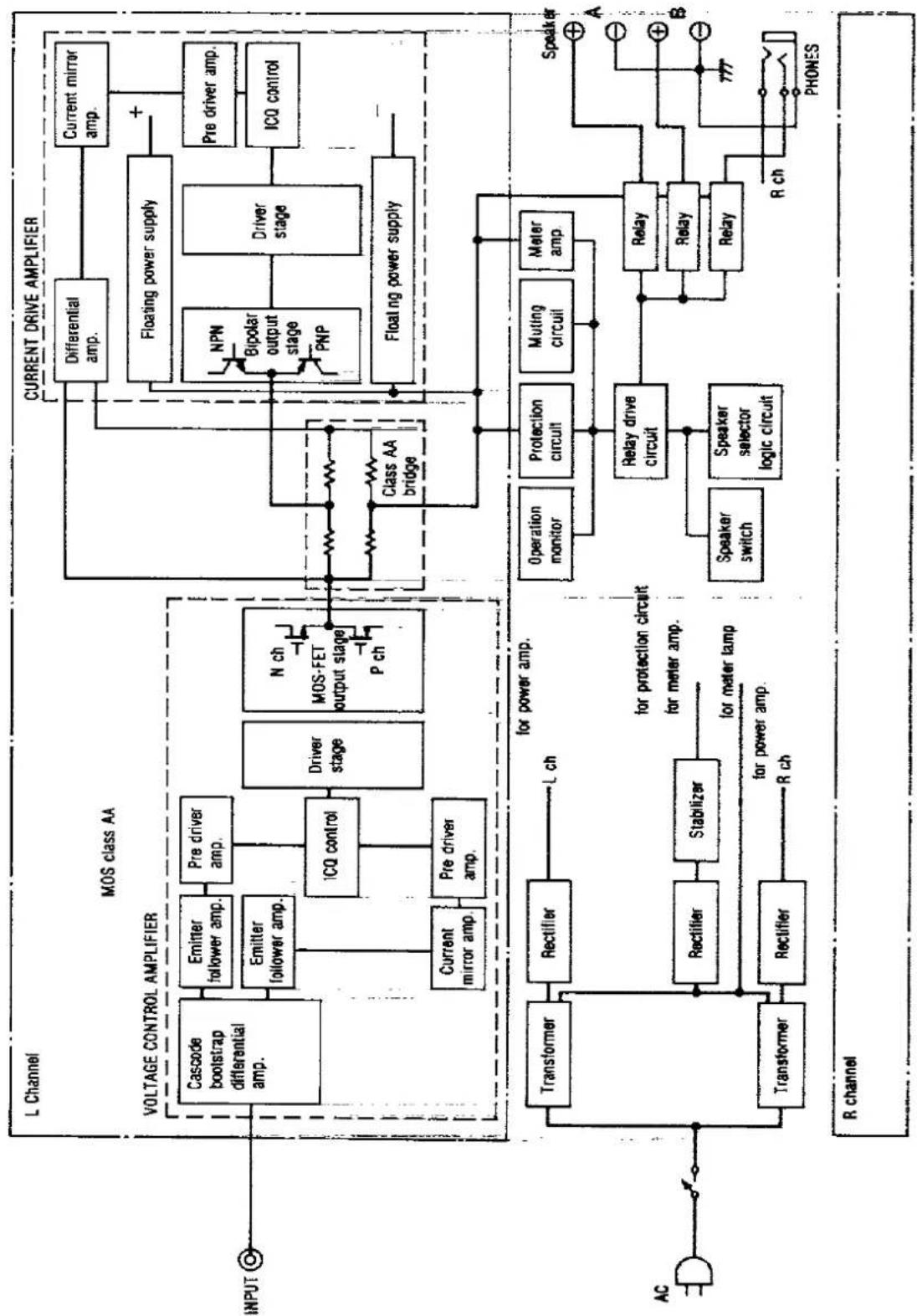
flowchart
graph TD
    subgraph_L_Channel[" L Channel "]
        A["INPUT"] --> B["Cascode bootstrap differential amp."]
        B --> C["Emitter follower amp."]
        C --> D["Pre driver amp."]
        D --> E["ICQ control"]
        E --> F["Driver stage"]
        F --> G["N ch MOS-FET output stage P ch"]
        G --> H["Class AA bridge"]
        H --> I["Differential amp."]
        I --> J["Current mirror amp."]
        J --> K["Floating power supply"]
        K --> L["Pre driver amp."]
        L --> M["ICQ control"]
    end

    subgraph_R_CHANNEL[" R channel "]
        N["AC"] --> O["Transformer"]
        O --> P["Rectifier"]
        P --> Q["L ch"]
        Q --> R["for power amp."]
        R --> S["for protection circuit for meter amp."]
        S --> T["for meter tamp for power amp."]
        T --> U["Stabilizer"]
        U --> V["for meter tamp for power amp."]
        V --> W["Transformer"]
        W --> X["Rectifier"]
        X --> Y["R ch"]
    end

    subgraph_CURRENT_DRIVE_AMPLIFIER[" CURRENT DRIVE AMPLIFIER "]
        Z["Current drive amplifier"] --> AA["Differential amp."]
        AA --> AB["Current mirror amp."]
        AB --> AC["Floating power supply"]
        AC --> AD["NPN Bipolar output stage PNP"]
        AD --> AE["Driver stage"]
        AE --> AF["Pre driver amp."]
        AF --> AG["ICQ control"]
        AH["Relay drive circuit"] --> AI["Relay"]
        AI --> AJ["Relay selector logic circuit"]
        AK["Speaker switch"] --> AL["Speaker selector logic circuit"]
        AM["Protection circuit"] --> AN["Muting circuit"]
        AO["Operation monitor"] --> AP["Operation monitor"]
        AQ["Relay drive"] --> AR["Relay drive"]
        AS["Speaker"] --> AT["R ch"]
        AU["PROtection"] --> AV["Protection circuit"]
        AW["Muting circuit"] --> AX["Protection circuit"]
        AY["Meter amp"] --> AZ["Muting circuit"]
        BA["Relay"] --> BB["Relay"]
        BC["Relay"] --> BD["Relay"]
    end

    subgraph_R_channel[" R channel "]
        BE["A"] --> BF["B"]
        BG["B"] --> BH["R ch"]
        BI["RCH"] --> BJ["PHONES"]
    end
Suggestions for Safety
■ Use a standard AC wall outlet
- Use of an AC power source of high voltage, such as for an air conditioner, is very dangerous.
There is the possibility that a fire might be caused by making such a connection.
- A DC power source cannot be used.
Be sure to check the power source carefully, especially on a ship or other place where DC is used.
■ Grasp the plug when disconnecting the power supply cord
- Wet hands are dangerous.
A dangerous electric shock may result if the plug is touched by wet hands.
- Never place heavy items on top of the power supply cord, and never force it to bend sharply.
■ Place the unit where it will be well ventilated
Place this unit at least 10 cm (4") away from wall surfaces, etc. Be careful that curtains and similar materials do not obstruct the ventilation holes.
■ Avoid places such as the following:
In direct sunlight or in other places where the temperature is high.
In places where there is excessive vibration or humidity.
Such conditions might damage the cabinet and/or other component parts and thereby shorten the unit's service life.
■ Be sure to place the unit on a flat, level surface.
If the surface is inclined, a malfunction may result.
■ Never attempt to repair or reconstruct this unit
A serious electric shock might occur if this unit is repaired, disassembled or reconstructed by unauthorized persons, or if the internal parts are accidentally touched.
■ Take particular care if children are present
Never permit children to put anything, especially metal, inside this unit. A serious electric shock or malfunction could occur if articles such as coins, needles, screwdrivers, etc. are inserted through the ventilation holes, etc. of this unit.
■ If water is spilled on the unit
Be extremely careful if water is spilled on the unit, because a fire or serious electric shock might occur. Immediately disconnect the power cord plug, and consult with your dealer.
■ Avoid spray-type insecticides
Insecticides might cause cracks or "cloudiness" in the cabinet and plastic parts of this unit. The gas used in such sprays might, moreover, be ignited suddenly.
■ Never use alcohol or paint thinner
These and similar chemicals should never be used, because they might cause flaking or cloudiness of the cabinet finish.
■ Disconnect the power supply cord if the unit will not be used for a long time
If the unit is left for a long time with the power ON, this will not only shorten its useful operation life, but may also cause other troubles.
■ If trouble occurs
If, during operation, the sound is interrupted or indicators no longer illuminate, or if abnormal odor or smoke is detected, immediately disconnect the power cord plug, and contact your dealer or an Authorized Service Center.
Troubleshooting Guide

Before requesting service for this unit, check the chart below for a possible cause of the problem you are experiencing. Some simple checks or a minor adjustment on your part may eliminate the problem and restore proper operation.
If you are in doubt about some of the check points, or if the remedies indicated in the chart do not solve the problem, refer to the directory of Authorized Service Centers (enclosed with this unit) to locate a convenient service center, or consult your Technics dealer for instructions.
| Problem | Probable cause(s) | Suggested remedy |
| No sound is heard when the power is switched ON. | The power cord plug is not completely inserted. | • Confirm that the power cord plug is connected completely. |
| Connections are Incomplete or incorrect to the speaker systems; etc. | • Check to be sure that all connection wires are correctly connected. | |
| The speaker selector is set incorrectly. | • Set it to the correct position. | |
| When listening to stereo sound, the sound lacks depth (i.e. thin bass, tinny sound). | One of the speakers is connected out of phase [(+)→(-), (-)→(+)]. | • Reconnect the speakers maintaining proper polarity [i.e., (+)→(+), (-)→(-)]. |
| When listening to stereo sound, the left and right sounds are reversed. | The left and right speaker connections, source connections are reversed. | • Check all connections and correct them if necessary. |
| A low-pitched noise ("hum" or "buzz") is heard. | The power cord or a fluorescent light, etc., is near the connection wires. | • Try separating this unit as far as possible from the electric appliance. |
| Sound stops during a performance, or no sound is heard when the power is switched ON. | The protection circuitry has functioned because the positive and negative speaker connection wires are "shorted" or speaker systems with an impedance less than the indicated rated impedance of the amplifier are used, or DC voltage appears in the output, causing the protection circuitry to function. | • Switch OFF the power, and after determining and correcting the cause, switch ON the power once again.• Use a speaker system of the proper impedance rating. |
Maintenance
To clean this unit, use a soft, dry cloth.
For very dirty surfaces, dip a soft cloth in a weak soap-and-water solution and wring well. After cleaning, wipe with a soft, dry cloth.
Never use alcohol, paint thinner, benzine, or a chemically treated cloth to clean this unit.
Such chemicals may damage the unit's finish.
Matsushita Electric Industrial Co., Ltd.
Central P.O. Box 288, Osaka 530-91, Japan