VHR-7700 - Videorekorder SANYO - Kostenlose Bedienungsanleitung
Finden Sie kostenlos die Bedienungsanleitung des Geräts VHR-7700 SANYO als PDF.

| Produkttyp | Videorekorder (VHS) |
| Marke | Sanyo |
| Modell | VHR-7700 |
| Abmessungen (B x H x T) | ca. 435 x 96 x 350 mm |
| Gewicht | ca. 4,5 kg |
| Stromversorgung | 220–240 V AC, 50 Hz |
| Leistungsaufnahme | ca. 20 W |
| Bandformat | VHS-Kassetten |
| Aufnahmemodi | SP, LP, EP (je nach Modell) |
| Timer-Aufnahme | Ja, programmierbar |
| Wiedergabe | VHS-C über Adapter |
| Anschlüsse | HF-Antenneneingang, SCART, RCA (Cinch) Ausgang |
| Fernbedienung | Ja, Infrarot |
| Besondere Merkmale | Shuttle-Jog-Dial, Suchlauf, Automatische Kopfbearbeitung |
| Reinigung | Gehäuse mit trockenem Tuch abwischen; keine Flüssigkeiten verwenden |
| Sicherheitshinweise | Nur im Innenbereich verwenden; Gerät nicht öffnen; bei Gewitter Netzstecker ziehen |
| Ersatzteile / Reparatur | Ersatzteile über Fachhändler; Reparatur nur durch qualifiziertes Personal |
Häufig gestellte Fragen - VHR-7700 SANYO
Benutzerfragen zu VHR-7700 SANYO
0 Frage zu diesem Gerät. Beantworten Sie die, die Sie kennen, oder stellen Sie Ihre eigene.
Eine neue Frage zu diesem Gerät stellen
Laden Sie die Anleitung für Ihr Videorekorder kostenlos im PDF-Format! Finden Sie Ihr Handbuch VHR-7700 - SANYO und nehmen Sie Ihr elektronisches Gerät wieder in die Hand. Auf dieser Seite sind alle Dokumente veröffentlicht, die für die Verwendung Ihres Geräts notwendig sind. VHR-7700 von der Marke SANYO.
BEDIENUNGSANLEITUNG VHR-7700 SANYO
Instruction Manual
Video cassette recorder
VHR-7700E


Hi-Fi
L P Mode :- Audio only
natural_image
Front view of a black rectangular electronic device with a display screen and control buttons (no visible text or symbols)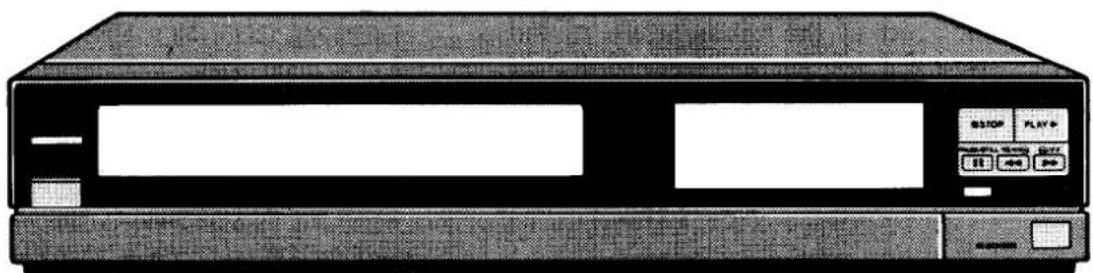
natural_image
Front view of a vintage electronic device with control buttons and drive casing (no visible text or symbols)Congratulations. You are now the owner of a SANYO Video Cassette Recorder.
Please read these instructions before operating the VCR.
VHS HQ PAL
☐ This VCR is based on a VHS-PAL signal system. Only video cassette bearing the VHS symbol can be used.
□ Video cassette recorders bearing the “HQ” mark incorporate VHS high picture quality technology. Note that there is interchangeability with former VHS video cassette recorders.
CAUTION
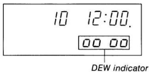
DEW SENSOR
When operating the VCR, always pay attention to the following.
☐ If the DEW indicator (00 00) illuminates, halt all operations until the DEW indicator goes off.
□ Because condensation will form gradually, the DEW indicator may not illuminate immediately when the temperature or humidity has changed abruptly, even though dew has formed inside the VCR.
☐ Do not operate the VCR until its temperature has stabilized at the temperature of the room where it will be operated. This may take up to 20 minutes.

natural_image
Cartoon illustration of a child sleeping in bed near a clock, with a snow-covered tree and blanket nearby (no text or symbols)IMPORTANT
The wires in this mains lead are coloured in accordance with the following code:

☐ As the colours of the wires in the mains lead of this apparatus may not correspond with the coloured markings identifying the terminals in your plug proceed as follows.
☐ The wire which is coloured blue must be connected to the terminal which is marked with the letter N or coloured blue or black.
☐ The wire which is coloured brown must be connected to the terminal which is marked with the letter L or coloured brown or red.
☐ Do not connect either wire to the Earth terminal.
CONTENTS
PRECAUTIONS.... 2
FEATURES 3
CONNECTIONS.... 4
ADJUSTING THE TV RECEIVER (RF CHANNEL SETTING)...... 5
PART NAMES AND FUNCTIONS 6
REMOTE CONTROL UNIT 7
CLOCK SETTING....9
TUNING CONTROL ADJUSTMENTS.... 10
CASSETTE LOADING AND UNLOADING...... 12
RECORDING TELEVISION BROADCASTS ..... 13
RECORDING NICAM TV BROADCASTS...... 15
Hi-Fi AUDIO ONLY RECORDING/PLAYBACK .... 16
FM SIMULCAST RECORDING....17
CAMERA RECORDING/ CAMCORDER DUBBING .... 18
DUBBING 18
TIMER RECORDING 19
PLAYBACK 22
PLAYBACK Hi-Fi STEREO/BILINGUAL PROGRAMMES 24
INDEX SEARCH FUNCTION.... 25
GO TO SEARCH FUNCTION 27
SPECIAL CODE FUNCTION....28
REPAIRS....29
TROUBLESHOOTING 29
SPECIFICATIONS 29
WARRANTY TO C. ISTOMER 30
PRECAUTIONS
OPERATING PRECAUTIONS
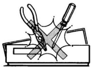
□ Removing the cabinet and touching the inside of the VCR with your hand, a screw-driver, or anything else, is not only harmful to the unit, but is also dangerous.
TO PREVENT FIRE OR SHOCK HAZARD, DO NOT EXPOSE THIS PRODUCT TO RAIN OR MOISTURE.
☐ The unauthorized recording of television programmes, video tapes, films and other such material may involve infringement of copyright or the rights of third parties.
☐ Be sure to use this VCR only in a temperature range of 5^ C to 35^ C and less than 85% humidity.
☐ This VCR is sensitive to magnetism. Do not expose to a magnetic source.
Place the VCR on a stable, level surface. Never subject it to violent shaking or any other shock or impact.
☐ Do not block the air vents that are provided to prevent the temperature inside the VCR from rising excessively.
The POWER button of this VCR is a secondary circuit, and does not disconnect the unit from the AC power source, even if the button is in the stand-by position, as long as the power cord is connected to AC electrical outlet.
Note: Stand-by is the condition in which the date and time are displayed.
The digital display on this VCR appears as shown below when the power is turned on and off, respectively.
Power on:
$$ \begin{array}{l l} 1 2 _ {\mathrm{AFT}} & 9: 3 0 \ 0 _ {\mathrm{H}} & 0 0 _ {\mathrm{M}} 0 0 _ {\mathrm{S}} ^ {\mathrm{M}} \end{array} $$
Power off:
$$ \begin{array}{l l} & 9: 3 0 \ \text { DATE } & 1 0 \quad 1 2 8 9 \end{array} $$
You cannot play back tapes recorded in the "LP (Long Play)" mode of this VCR on a VCR which has only a "SP (Standard Play)" mode.
natural_image
Illustration of a hand using pliers to cut a rectangular object, with no visible text or symbols.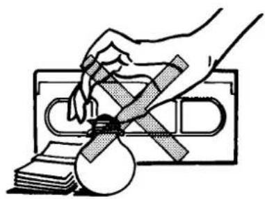
natural_image
Illustration of a hand holding a cross-shaped object over stacked documents (no text or symbols)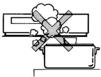
natural_image
Simple line drawing of a cooking pan with a crossed-out box and smoke, no text or symbols present.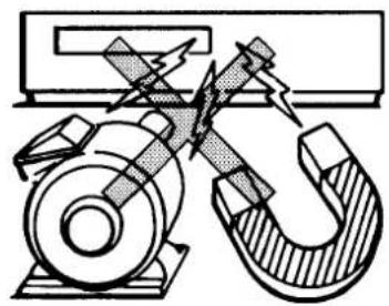
natural_image
Technical diagram of a mechanical assembly with a hammer and nut, showing internal components and motion lines (no text or labels)
natural_image
Pure technical diagram of a mechanical assembly with no text, numbers, or symbols
natural_image
Simple line drawing of a rectangular object with a cross-shaped mark on top, connected by diagonal lines to a rounded base (no text or symbols)FEATURES
□ VHS high quality picture technology
□ 39-position voltage synthesizer tuner
□ SP/LP two speed recording/playback
□ Built-in 1 year, 6-event timer with every day function
☐ Hi-Fi audio stereo system with audio frequency modulation recording
□ Stereo and bilingual programme recording capability
□ NICAM ready
□ QSR (Quick Start Recording) timer
□ Blank search function
□ TV monitor function
□ Forward and reverse colour picture search
□ Still picture playback
□ Frame advance playback
□ Linear time counter
□ Various convenient automatic functions
□ Special code operation
□ Multi-function infra-red remote control
Direct power on and go
Power on
If a control button is pressed while the VCR is in stand-by, power is supplied directly and the VCR operates.
Example: If you press the PLAY button, the VCR will be turned on and start playback.
Note: This function is not provided for the REC button. This is to prevent the VCR from being inadvertently put into a video recording condition. Normally, when only power on is required, press the POWER button.
Power off
The video recorder will be turned off if you press the POWER button.
Direct power on and go
When the VCR is in stand-by, press any one of the control buttons to turn on the power and perform the respective button's function.
AUTO power on
The power is automatically switched on as a cassette is inserted even when the VCR is in the stand-by condition.
MEP (Miss Erasure Prevention) eject
A video cassette will automatically be ejected if recording is attempted on a video cassette without an erasure-prevention tab.
Auto rewind
The VCR automatically rewinds the tape at the end of the tape.
Note: This function does not operate for timer recording or QSR time recording.
Auto play
The VCR will playback a tape automatically when a video cassette is inserted whose erasure-prevention tab has been removed.
Auto eject
When a video cassette without an erasure-prevention tab is played to the end of the tape, the tape will be automatically rewound and then the cassette will be ejected.
Off power eject
A video cassette will be ejected when the EJECT button is pressed even with the VCR in stand-by condition.
Auto-timer stand-by
When timer setting is completed, the VCR's power is automatically switched off to timer stand-by mode.

natural_image
Illustration of a person watching a woman's face with musical notes (no text or symbols)CONNECTIONS
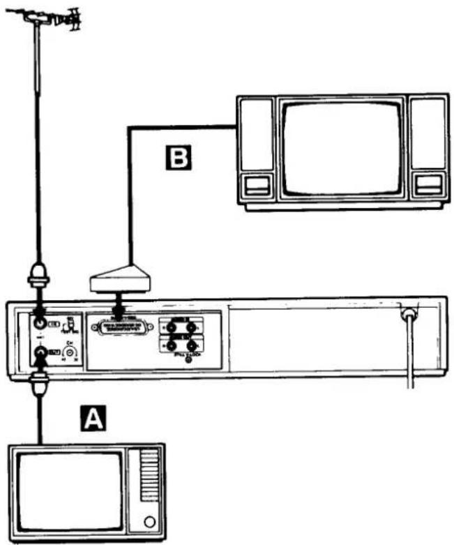
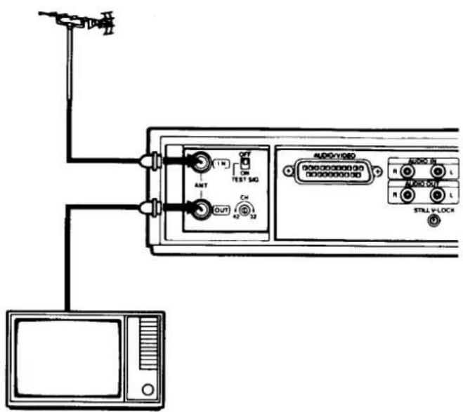
A ANTENNA CONNECTION
☐ Un-plug the antenna cable from your TV receiver and reconnect to the terminal marked "ANT IN" on the VCR.
□ Connect the antenna cable supplied with the VCR to the "ANT OUT" terminal on the VCR. Connect the other end of this antenna cable to the TV receiver.
☐ Insert the plug of the power cord into the wall socket.
B AV-CONNECTION
If the TV receiver in use has AV terminals, connection B can be used as well as connection A. The AV cable is sold separately. Obtain it from your dealer if necessary.
□ Connect the AUDIO/VIDEO terminal on the VCR to the AV terminal on the TV receiver.
☐ The advantage of this connection is a superior quality of picture and sound during playback.
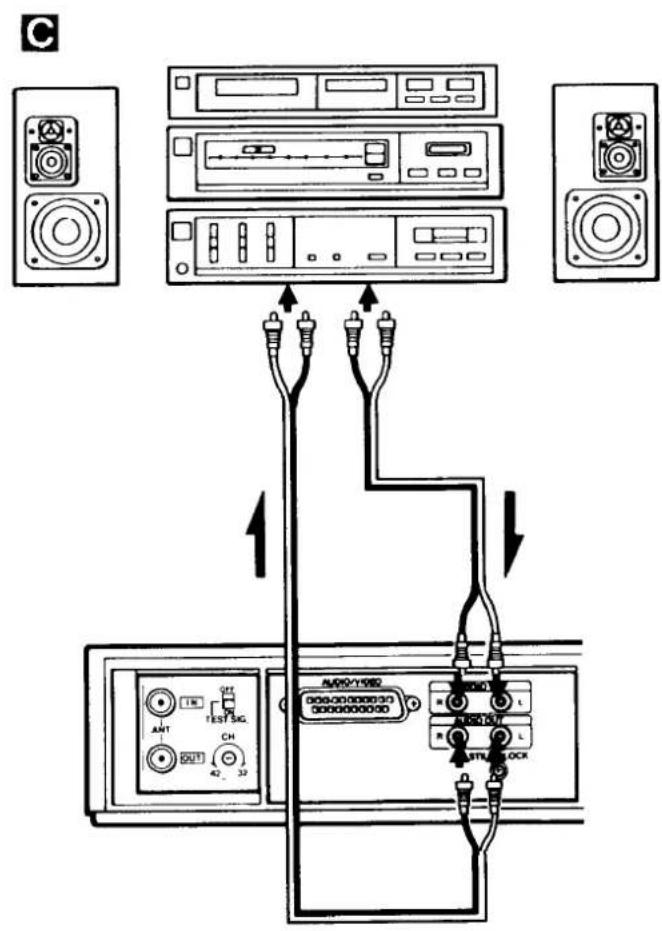
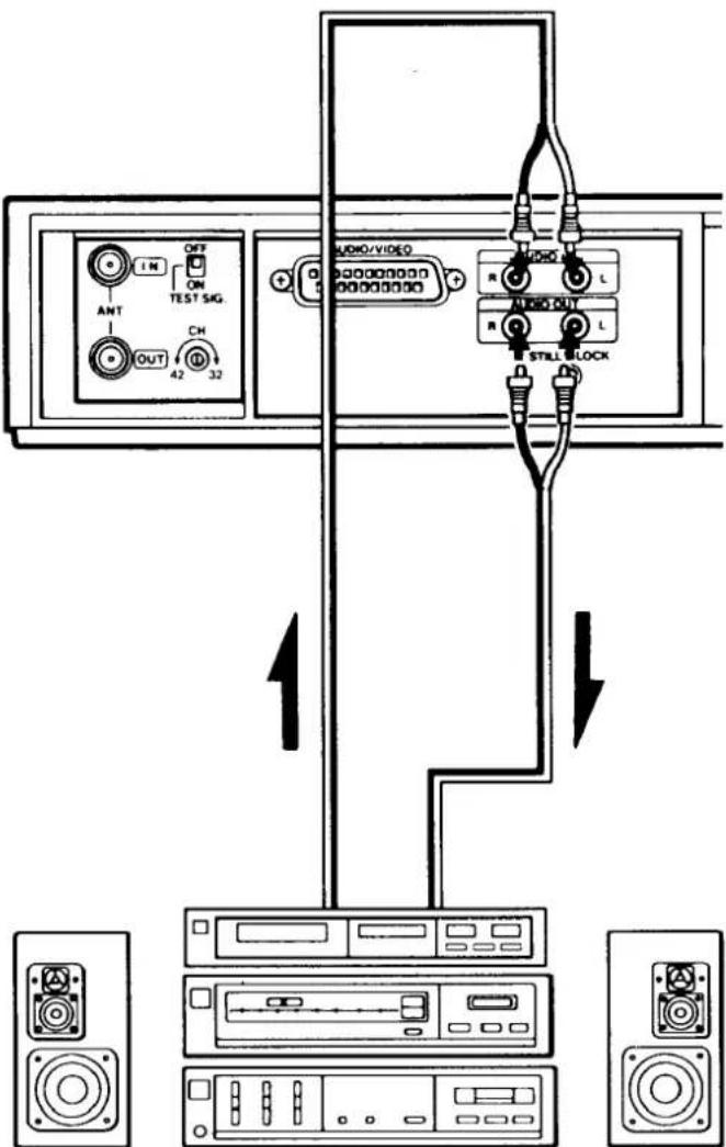
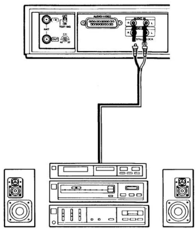
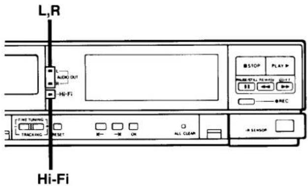
C Hi-Fi AUDIO CONNECTION
☐ For sound playback over a hi-fi system, connect the AUDIO OUT (L, R) terminal on the VCR to the audio input terminal on the hi-fi system.
☐ To record sound from a hi-fi system, connect the audio output terminal on the hi-fi system to the AUDIO IN (L, R) terminal on the VCR.
AV control function
If connections are made to an AV control compatible TV, the TV's input can be controlled at the VCR. This means that when the VCR's PLAY button is pressed, the TV input is switched automatically so that the TV functions as a video monitor.
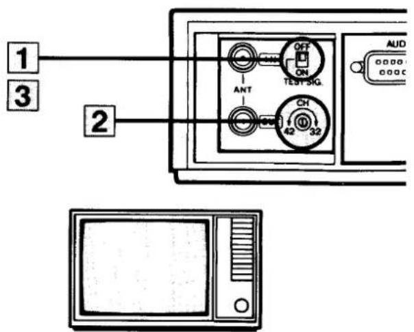
ADJUSTING THE TV RECEIVER (RF CHANNEL SETTING)
The following procedure is only necessary if no AV connection is made to the TV. With AV connection, simply switch the TV to AV mode.
1 Set the TEST SIG. switch to the "ON" position.
2 Select a spare programme position on the TV and adjust the tuning on the TV to the TEST Picture "Black and White Bars".
3 Switch the TEST SIG. to "OFF".
4 On playback of a tape FINE TUNE the TV if necessary.
5 The internal RF converter, converts the Audio/Video signal to an RF signal suitable for TV receivers.
The RF converter is factory pre-set to Channel 36, but is adjustable between channels 32 to 42. If you get interference on your usual TV programmes, turn the screw a small amount and follow items 1 to 4, repeat item 5 if necessary.
Note: RF channel setting is also possible using a pre-recorded VHS video cassette. Play back the tape and tune the TV receiver to obtain clear pictures and sound while monitoring the play-back picture on the TV screen.
Note: UHF television is broadcast on one of the UHF channels 21–68.
For example in the London area:
BBC 1 .... Channel 26
CHANNEL 4 .... Channel 30
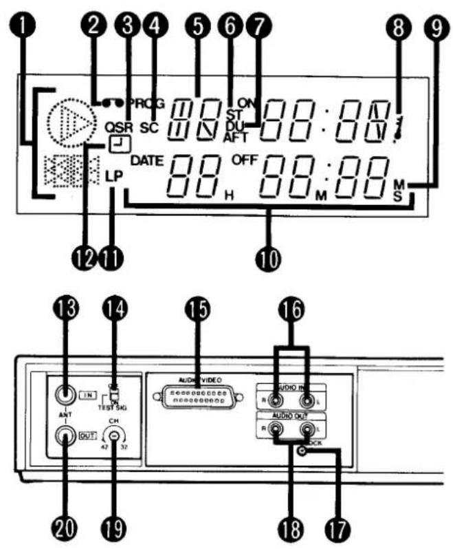
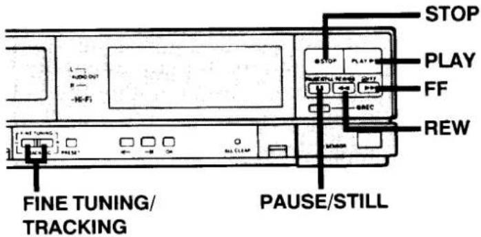
PART NAMES AND FUNCTIONS
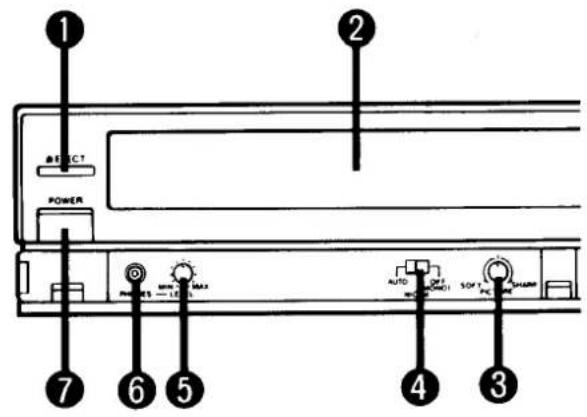
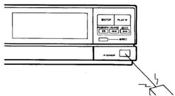
Front
① EJECT button
② Cassette loading compartment
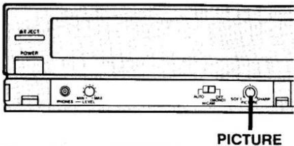
③ PICTURE sharpness control
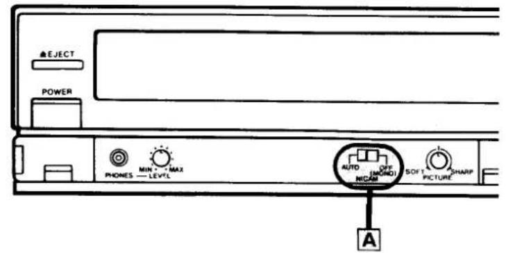
④ NICAM switch
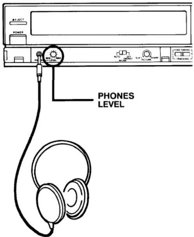
⑤ Head phones LEVEL control
⑥ Head PHONES jack
⑦ POWER button
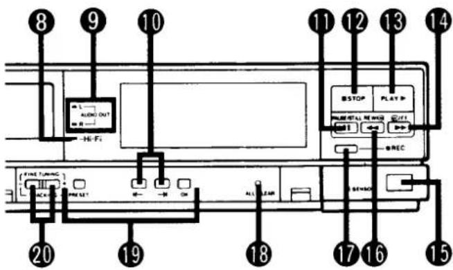
⑧ Hi-Fi mode indicator
⑨ AUDIO OUT indicator
10 ← : Channel down/Back
→: Channel up/Next
Use these buttons to select the desired channel. To select the AV input, press one of the selector buttons until "AU" appears on the display.
⑪ PAUSE/ STILL button
During playback: still picture.
During recording: pause during which no material will be recorded.
During still playback: frame advance
⑫ STOP button
13 PLAYback button
⑭ Fast-Forward button
⑮ Remote control detector
16 REWind button
⑰ RECORD button
18 ALL CLEAR button
When pressing the ALL CLEAR button, the digital display will read "88:88", so that the current time and the desired times for recording programmes can be reset.
□ Depress the ALL CLEAR button in the event that the function buttons cannot be activated.
19 Tuning controls
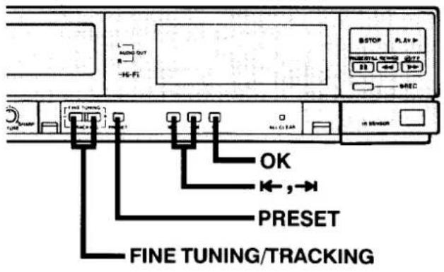
20 FINE TUNING/TRACKING controls
Each control should normally be set to the "basic position" described below.
For detailed operation instructions, refer to the page on which each control is explained.
③ PICTURE sharpness control – “centre position”
Adjust quality of played-back picture. (See page 23)
④ NICAM switch – “AUTO”
When it is desired to record the NICAM broadcast FM monaural signal on the hi-fi track, set to OFF. (See page 15)
⑤ PHONES LEVEL control – “centre position”
Adjust head phone volume. (See page 24)
☐ When "LP" appears on the digital display, turn the "LP" display off with the remote control unit SP/LP button. When "LP" does not appear the unit is in "SP" mode at its basic position.
CAUTION: In "LP" mode the picture is not recorded. When recording only sound in hi-fi, record in "LP" mode. (See page 16)
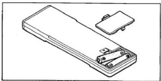
BATTERY INSERTION
- Open the lid.
- Insert 2 "AA (IEC R6)" 1.5 volt batteries (sold separately) as indicated by the (+) and (-) signs.
- Replace the lid.
natural_image
Line drawing of a handheld electronic device with a separate clip and housing (no text or symbols)Digital Display
① Function indicators
② Cassette loading indicator
③ QSR indicator
④ SC (simulcast) indicator
⑤ Channel position number
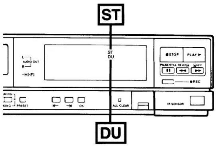
⑥ STereo indicator (ST)
⑦ Bilingual indicator (DU)
⑧ Key lock indicator
⑨ Counter memory indicator
10 Clock/Timer/Counter display
⑪ LP mode indicator
⑫ Timer indicator
Rear
⑬ ANTenna INput terminal
14 TEST SIGnal switch
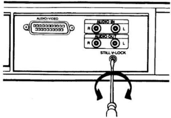
15 AUDIO/VIDEO terminal
16 AUDIO INput terminals (L, R)
17 STILL V-LOCK adjustment screw
18 AUDIO OUTPUT terminals (L, R)
⑲ CHannel adjustment screw
⑳ ANTenna OUTput terminal
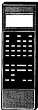
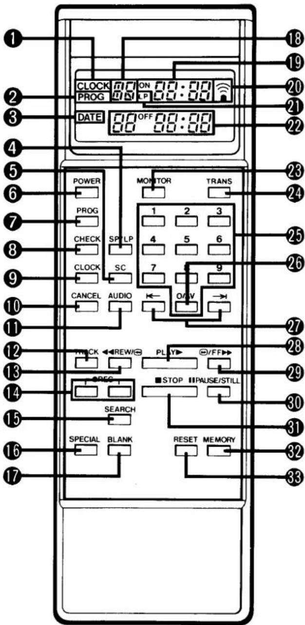
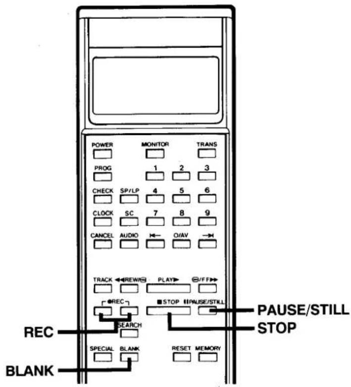
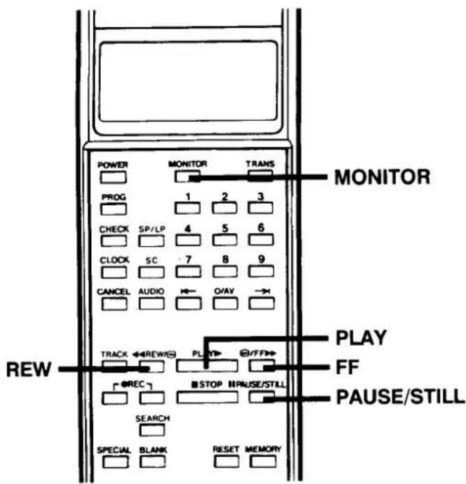
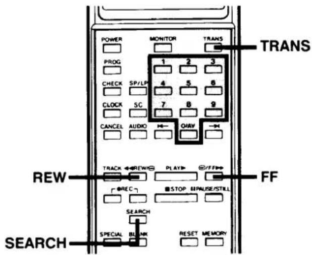
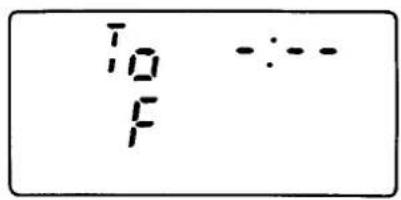
REMOTE CONTROL UNIT
This remote control unit is a multifunction unit equipped with an LCD panel.
Each operation can be set up while looking at the remote control unit LCD panel, then transmitted to the VCR. in addition to timer programming and time adjustments, convenient special functions can also be engaged with the remote control unit. For details, see separate entries for each operation.
Normally, time and date are displayed on the remote control unit LCD panel after clock setting is completed. When programming any type of data to be sent to the VCR, the display changes according to each mode.
Notes:
☐ Operate the remote control unit within a range of approx. 30° from the front of the VCR.
☐ Operate unit within approx. 6 m (20 ft.) from the front of the VCR.
☐ Battery life under normal operating conditions is about six months. If the battery become weak, the operable distance will decrease; when this occurs, replace the batteries.
☐ If the remote control unit is not to be used for a long period of time, remove the batteries.
☐ If the battery is removed, timer programmes and other memorized material are erased.
① CLOCK mode indicator
② PROGramme mode indicator
③ DATE mode indicator
④ SP/LP select button
⑤ SimulCast button
⑥ POWER button
⑦ PROGramme set
8 Programme CHECK
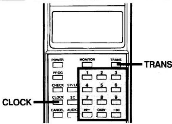
⑨ CLOCK set
10 Programme CANCEL
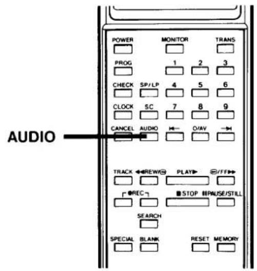
11 AUDIO output select button
⑫ Auto TRACKing button
⑬ REWind button
14 RECORD buttons
To record, press both of these buttons.
⑮ Index/Go to SEARCH
⑯ SPECIAL code
⑰ Search BLANK area
18 Switchable display
Channel position
Special code (SP)
Index search (Id)
Go to search (To)
External input mode (AU)
19 Switchable display
Clock
Timer on-time
Index number
Go to time
Special code number
20 Remote function indicator
②1 LP mode indicator
22 Switchable display
Date
Timer off-time
23 Tuner MONITOR
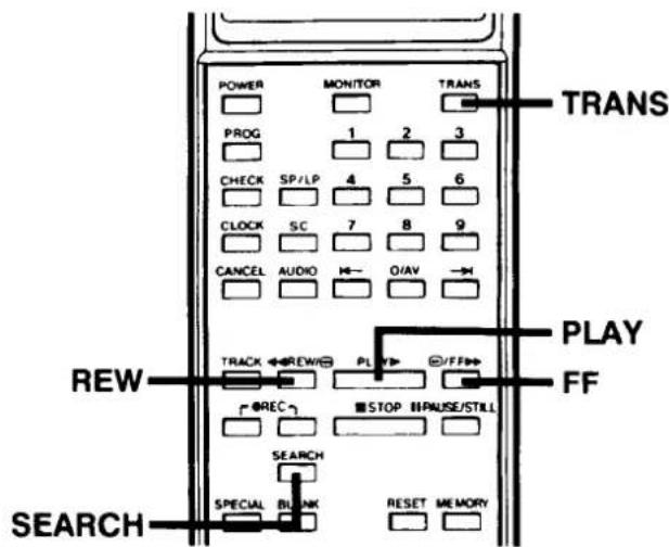
24 Programme TRANSFER
25 Numeric buttons
26 AV select button (0/AV)
To select the external input mode, press this button.
27 ← : Channel down/Back
→: Channel up/Next
28 PLAYback button
29 Fast-Forward button
30 PAUSE/ STILL button
③1 STOP button
32 Counter MEMORY button
33 Counter RESET button
1
2
3
4
5
6
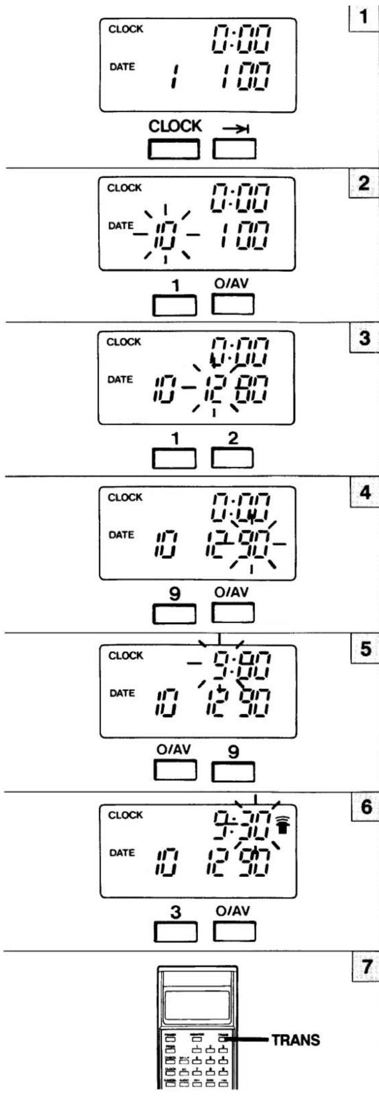
CLOCK SETTING
☐ Clock setting takes place with the remote control unit.
☐ Clock setting can be changed by pressing the ← or → button until the desired figure flashes. Then input correct number.
☐ When a one digit number is going to be set, press "0/AV" first and then the desired number (eg: In case of 9: press "0/AV" and then "9".)
Example: 9:30 December 10, 1990
1 Press the CLOCK button, then press the → button once.
2 Set the DAY with numeric buttons.
Example: DAY = 10
3 Set the MONTH with numeric buttons.
Example: MONTH = 12
4 Set the YEAR with numeric buttons.
Example: YEAR = 90
5 Set the HOUR with numeric buttons.
Example: HOUR = 09
6 Set the MINUTE with numeric buttons.
Example: MINUTE = 30
7 While the remote function indicator ( 📞 ) blinks, press the TRANS button.
☐ Whenever the remote function indicator ( ( \overline{\overline{\overline{\overline{\overline{\overline{\overline{\overline{\overline{\overline{\overline{\overline{\overline{\overline{\overline{\overline{\overline{\overline{\overline{\overline{\overline{\overline{\overline{\overline{\overline{\overline{\overline{\overline{\overline{\overline{\overline{\overline{\overline{\overline{\vee}}}}}}}}}}}}}}}}}}}}}}}}}}}}}}}}}}}}}}}}}}}}}}}}}}}}}}}}}}}}}}}}}}}}}}}}}}}}}}}}}}}}}}}}}}}}}}}}}}}}}}}}}}}}}}}}}}}}}}}}}}}}}}}}}}}}}}}}}}}}}}}}}}}}}}}}}}}}}}}}}}}}}}}}}}}}}}}}}}}}}}}}}}}}}}}}}}}}}}}}})
Seconds Counter Adjustment
On the VCR side, the seconds counter starts from "00" seconds immediately upon transmission from the remote control unit. Adjust the seconds counter accurately for co-ordination between MINUTE adjustment and transmission period timing.
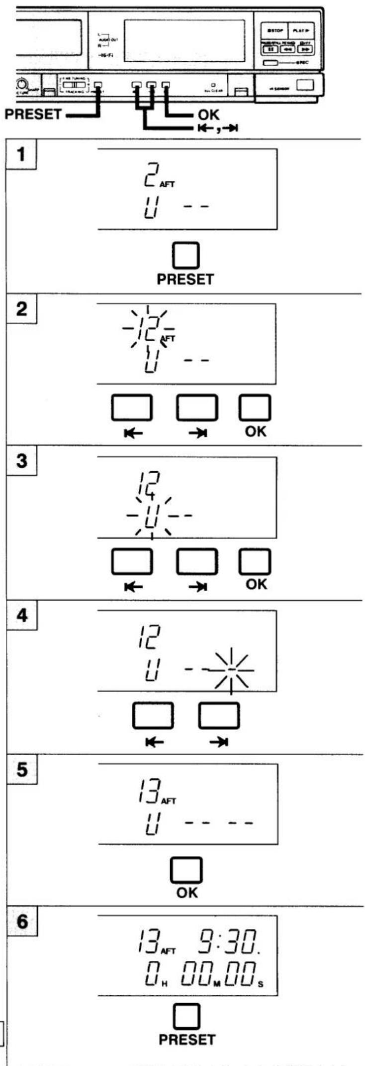
TUNING CONTROL ADJUSTMENTS
Check before starting
■ Set the TV receiver to the programme previously preset for the VCR (page 4) or to AV mode if those connections are in use.
Example: To preset a TV transmission to programme position number "12".
1 Press the tuning PRESET button.
2 Select the desired programme position number (Example: "12") by pressing the ← or → button. Then press the OK button.
3 If the unit is in the SKIP (S) mode, use the ← or → button to switch to the band indication "U". Then press the OK button.
☐ When the ← or → button is pressed, the character "U" or "S" (skip) will be sequentially displayed as a band indicator.
| Band Indicator | Channel Range |
| U | 21 to 69 |
| S | Skip function (See page 11.) |
4 When the ← or → button is pressed, a channel being used for broadcast will be automatically found.
Note: Since the lowest position of the band becomes the tuning point when a band has been selected, at the beginning please push the → button and then start searching for the channel.
When a channel is located by channel searching, the search stops and the programme indicator changes from blinking to steady illumination, and at the same time, "AFT" indicator illuminates. Check the TV screen to confirm that the located transmission is the one you want and, if it is, proceed to step 5. If it is not, repeat step 4.
5 Press the OK button, and the station selected is memorized.
When presetting another programme position number, repeat steps 2 to 5.
6 To return to normal operation press the PRESET button, the display will return to normal.
SKIP FUNCTION
The skip function gives you the possibility to jump the unused programme positions.
Example: To skip programme position number "10".
1 Press the PRESET button.
2 Press the ← or → button to select the programme position number (Example: "10") to be skipped. Then press the OK button.
3 Press the ← or → button until the band indicator shows "S".
Note: "S" denotes SKIP.
4 Press the OK button.
5 Press the PRESET button to return to normal operation, the display will return to the normal display.
Note:
To cancel the SKIP mode, press the ← or → button once again to select the band to be received, and then preset once again (see page 10).
"PICTURE" FINE TUNING
Once a preset channel is tuned, the AFT is switched ON automatically. However, there are circumstances where reception may be improved i.e. if signals are weak or if interference occurs. If this is the case, Fine Tune as follows:
1 Press the ← or → button to select the unsatisfactory programme.
2 Press the PRESET button.
3 Press the FINE TUNING/TRACKING (−or +) button until the best possible picture and sound is obtained. When the FINE TUNING/TRACKING button is pressed the AFT indicator is turned off, allowing fine tuning adjustment.
4 Then press the PRESET button.
Note: To turn the AFT back on, select the required programme number, press the PRESET button once, press the OK button and press the PRESET button again.
If the AFT does not come on despite the above procedure, preset it once again as in Tuning Control Adjustments page 10.
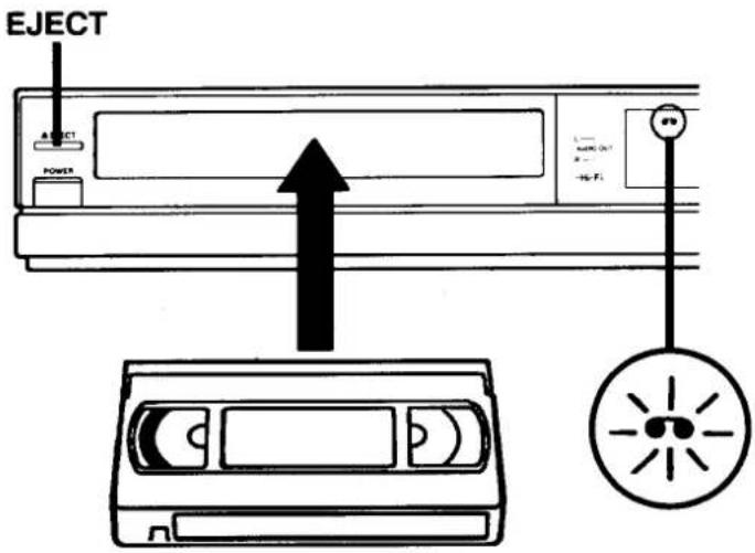
CASSETTE LOADING AND UNLOADING
LOADING
When a video cassette is inserted, it will be loaded automatically and the cassette indicator will illuminate.
UNLOADING
The video cassette will be unloaded when the EJECT button is pressed.
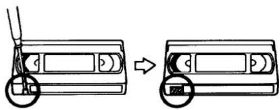
ERASURE-PREVENTION TAB
If the erasure-prevention tab on the back of the video cassette is removed, it can not be recorded. This tab is designed to prevent the accidental erasure of recorded material. (The tab should be snapped off at its base, and removed completely.)
To record onto the same cassette again, place two layers of adhesive tape over the space where the tab was, so as to cover the space completely.
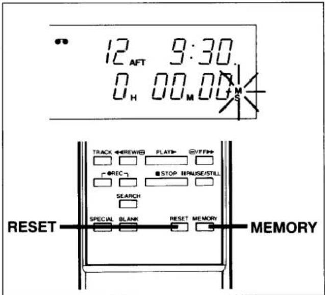
COUNTER MEMORY
This convenient feature for finding the beginning of a specific recording etc., is made possibly by the "Linear Time Counter" that indicates the tape run time in seconds.
☐ Whenever you load a cassette tape, the counter will be reset to "0H00M00s".
☐ The counter operates using control signals which are recorded on the tape, hence if you playback a tape which has nothing recorded on it, the counter will not operate.
1 Press the RESET and MEMORY buttons before starting recording or playback. The zero point of the counter is now memorized and the memory indicator "M" will illuminate.
2 When the REW button is pressed at the end of recording, or playback, tape will be rewound automatically to the memorized position and then stops.
☐ When rewinding further back from position “0H00M00s,” the counter shows figures beginning with “—”.
☐ The tape stops at the memorized position even with fast forward.
CAUTION:
Do not put your hand or other objects behind the cassette door because of the risk of injury or an accident.
Particularly keep small children away from the VCR.
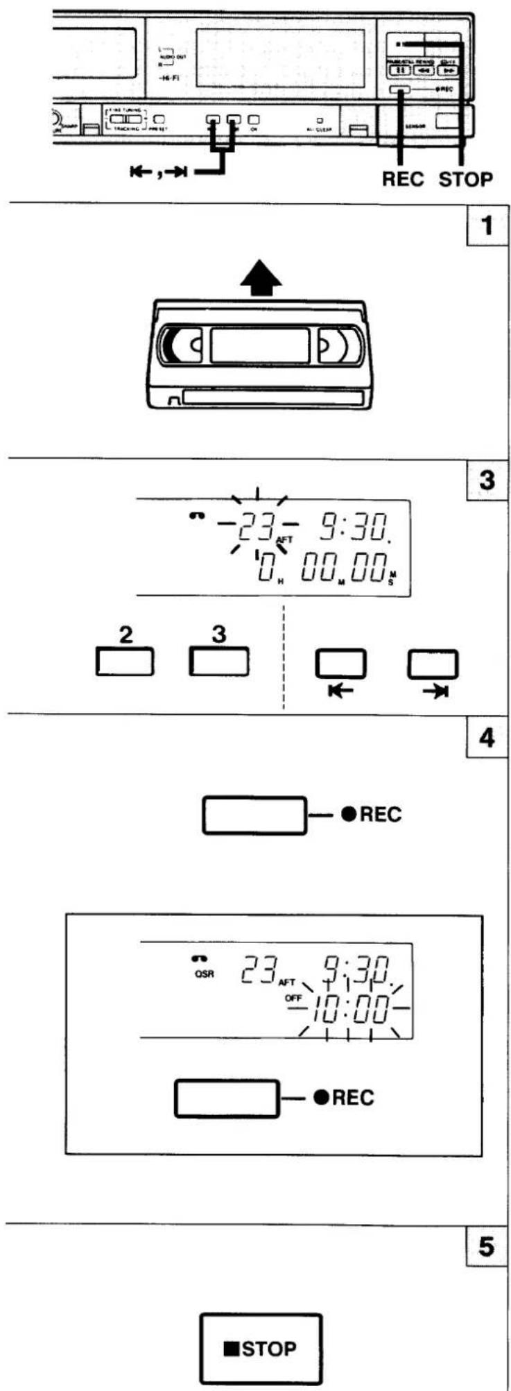
RECORDING TELEVISION BROADCASTS
Check before starting
To monitor the selected recording material set the TV to receive the VCR's programme (or AV mode).
1 Insert a video cassette.
2 Press the numeric buttons or ←, → button, to select the programme to be recorded. Example: "23"
3 Press the REC button.
□ Video recording starts. This is the normal video recording procedure.
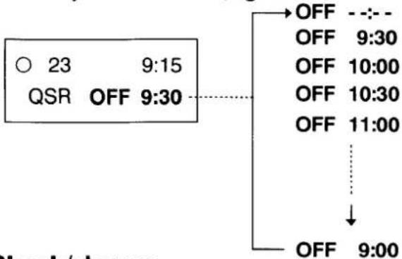
QUICK START RECORDING (QSR) TIMER
Timer Recording is simple.
1 Press the REC button to start recording.
2 Then press the REC button again.
The "OFF - - : - -" indication will light on the VCR display.
Within 10 seconds, use the REC button to set the recording end time. You can set the recording end time in units of 30 minutes.
From your current time, eg. 9:15.
flowchart
graph TD
    A["QSR 23 9:15"] --> B["OFF 9:30"]
    B --> C["OFF 11:00"]
    C --> D["OFF 9:00"]
    style A fill:#f9f,stroke:#333
    style B stroke-dasharray: 5 5
    style C stroke-dasharray: 5 5
    style D stroke-dasharray: 5 5
Check/change
When the REC button is pressed during QSR recording, the QSR ending time will be displayed for 10 seconds. The QSR ending time can be changed by pressing the REC button during this 10 seconds period.
4 To stop the recording, press the STOP button.
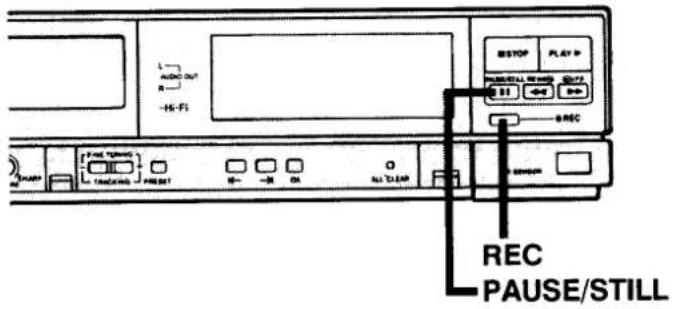
OTHER RECORDING POSSIBILITIES
If you wish to avoid recording unwanted material
1 During recording, press the PAUSE/STILL button. The TV picture will not be recorded.
2 Press the PAUSE/ STILL button or REC button, and the recording will resume.
Note: If REC PAUSE mode continues for about five minutes, the VCR will automatically go into the stop mode in order to protect the tape from damage.
Recording one programme while watching another
1 Start recording the desired TV programme, selected on the VCR.
2 Select any alternative programme position on your TV receiver.
USING THE BLANK SEARCH FUNCTION
The blank search function automatically searches for the next blank (unrecorded) portion of the tape, and stops the VCR at that position. This is convenient when you want to continue recording at the end of a previous recording.
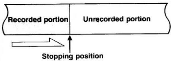
■ Press the BLANK button. The VCR will locate the next blank portion on the tape, and stop at that position.
If no blank portions are found all the way to the end of the tape, the VCR will switch directions and start searching toward the start of the tape.
If no blank portions are found, the VCR will go all the way to the start of the tape and then stop.
■ During the search, the words "TO End" will be shown in the VCR display.
Notes:
☐ The stopping position may vary slightly. Play back a few seconds of the tape to make sure it is at the position you want.
☐ This function may also stop the VCR during slight pauses (unrecorded portions) between taped programmes.
RECORDING NICAM TV BROADCASTS
The recording procedure is the same as that used for normal TV programme recording. The play-back procedure is also the same as that used for normal playback.
NICAM STEREO TV PROGRAMMES
When a NICAM stereo broadcast is received, the stereo indicator "ST" lights up.
When NICAM switch A is set to the AUTO position, the NICAM stereo signal is recorded on the hi-fi audio track and the regular (FM mono) signal is recorded on the normal audiotrack (mono).
NICAM BILINGUAL PROGRAMMES
When a NICAM bilingual broadcast is received, the bilingual indicator "DU" lights up.
When NICAM switch A is set to the AUTO position, the NICAM bilingual signal is recorded on the hi-fi audio track, and the regular (FM mono) signal on the normal track (mono).
If it is desired to record a regular (FM mono) audio programme on the hi-fi audio track, set NICAM switch A to the OFF (MONO) position during the recording.
Depending on the broadcast type, an audio programme recorded on the hi-fi audio track or normal audio track will become as given in the following table.
MONITORING DURING RECORDING
The AUDIO button of the remote control unit can be used to select the sound track. (See page 24)
BROADCAST TYPE AND AUDIO PROGRAMME RECORDING PATTERNS
| Type of TV broadcast | A NICAM switch position | Hi-Fi audio track (2-channels) | Normal audio track (mono) | |
| L | R | |||
| Regular (FM mono) | Either position | FM mono | FM mono | FM-Mono |
| Regular (FM mono) + NICAM stereo (L/R) | “AUTO” | NICAM (L) | NICAM (R) | FM-Mono |
| “OFF (MONO)” | FM mono | FM mono | FM-Mono | |
| Regular (FM mono) + NICAM bilingual (A/B) | “AUTO” | NICAM (A) | NICAM (B) | FM-Mono |
| “OFF (MONO)” | FM mono | FM-Mono | FM-Mono | |
| Regular (FM mono) + NICAM mono (A) | “AUTO” | NICAM (A) | NICAM (A) | FM-Mono |
| “OFF (MONO)” | FM mono | FM-Mono | FM-Mono | |
Notes:
Regardless of the NICAM switch position, when a NICAM broadcast is stereo the "ST" indicator lights up; when it is bilingual, the "DU" indicator lights up.
☐ NICAM audio programmes are not recorded on the normal track. They are only recorded on the hi-fi track.
Hi-Fi AUDIO ONLY RECORDING/PLAYBACK
By using the characteristics of VHS Hi-Fi sound, this model can be used as a high-quality audio cassette recorder. When recording in the "LP" mode, you can record for a maximum of 8 hours using a single cassette (E-240).
The "LP" mode is provided as an "audio only" recording mode. In this mode, the video signal will not be recorded.
RECORDING
1 When you wish to listen to a programme source connected to the AUDIO IN (RCA) terminals, set the SC button on the remote control unit to the "SC" position. To listen to a source connected to the AUDIO/VIDEO (21-pin) connector, press the or button so that "AU" appears on the channel position number display, or press the "0/AV" button on the remote control unit. The unit is in "SC" mode when "SC" appears on the VCR digital display, and "AV" mode is set when "AU" appears.
2 Select your desired tape speed using the SP/LP button on the remote control unit. When you select the LP mode, the LP mode indicator will illuminate on the display.
3 Input the programme source.
4 To start recording, press the REC button.
PLAYBACK
☐ When the unit is put into the playback mode, it will automatically judge whether the loaded tape was recorded in the "SP" or the "LP" recording mode.
☐ To start playback press the PLAY button.
☐ The sound track can be selected with the AUDIO button of the remote control unit.
Notes:
☐ When recording the audio only of the programme source from the AUDIO IN (RCA) terminals, leave the VCR channel vacant.
☐ The sound recorded on a normal audio track in the "LP" mode is not frequency-compensated.
FM SIMULCAST RECORDING
You can record the FM simulcast TV programmes (stereo sound transmitted from an FM radio station) while recording the TV programme picture (video signals) from the TV aerial inputs.
1 Connect an audio equipment (FM tuner) to the AUDIO IN (RCA) terminals.
2 Set the SC button on the remote control unit to the "SC" position.
The unit is in "SC" mode when "SC" appears on the VCR digital display.
3 Turn in the station you wish on the recorder and the FM tuner.
4 To start recording, press REC button.
How FM simulcast programmes are recorded
Hi-fi audio track
The signal from the external AUDIO IN (RCA) terminals are hi-fi recorded (left and right).
Normal audio track
The TV broadcast is audio signal being received by the VCR's tuner is recorded (mono).
Video signal
The TV broadcast's video signal being received by the VCR's tuner is recorded.
The sound track can be selected using the AUDIO button of the remote control unit. (See page 24)
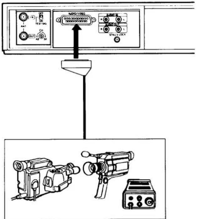
CAMERA RECORDING/ CAMCORDER DUBBING
Check before starting
■ Set the TV receiver to the "VCR" programme position.
NOTE: "AV" cannot be used to monitor camera recording.
■ Insert the video cassette.
■ Press the 0/AV button on the handset to obtain an AU on the programme position display, or use the ← or → buttons on the VCR.
The "AV" input status is the one in which "AU" is displayed in the channel position number display.
■ Select your desired tape speed using the SP/LP button.
1 Turn on the power of the video camera and adjust the focus, white balance, etc..
For Camcorder dubbing select PLAY on the Camcorder.
2 Press the REC button on the VCR or handset.
3 To stop the recording, press the STOP button on the VCR or handset.
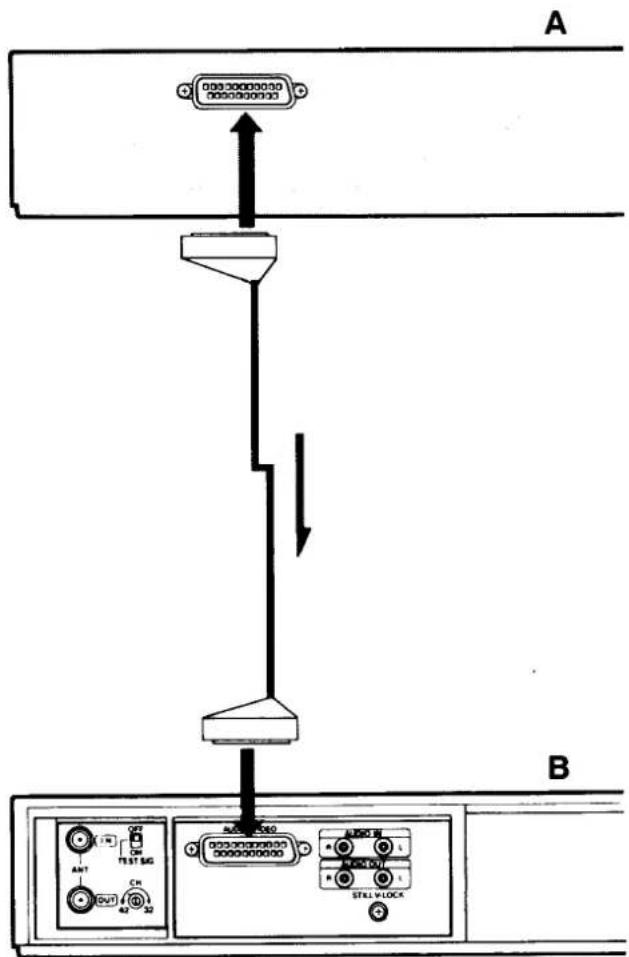
DUBBING
You can monitor a programme while dubbing by connecting a TV to the VCR B's ANT OUT terminal.
1 Connect VCR A and VCR B.
2 Insert the pre-recorded tape into the VCR A.
3 Insert the blank video cassette into the VCR B.
4 Set VCR B to the "AV (external)" input condition.
5 Press the PLAY button on the VCR A, and then press the REC button on the VCR B.
TIMER RECORDING
Timer recording enables you to carry out unattended video recording of television broadcasts at preset times. The following data must be entered to set the timer programme:
■ Channel position number
■ Day and month on which the recording is to be made
■ Time at which timer recording is to start (on-time)
■ Time at which timer recording is to stop (off-time)
Use the remote control unit to set the timer.
Before setting the timer programme, be sure that the present time shown in the display is correct.
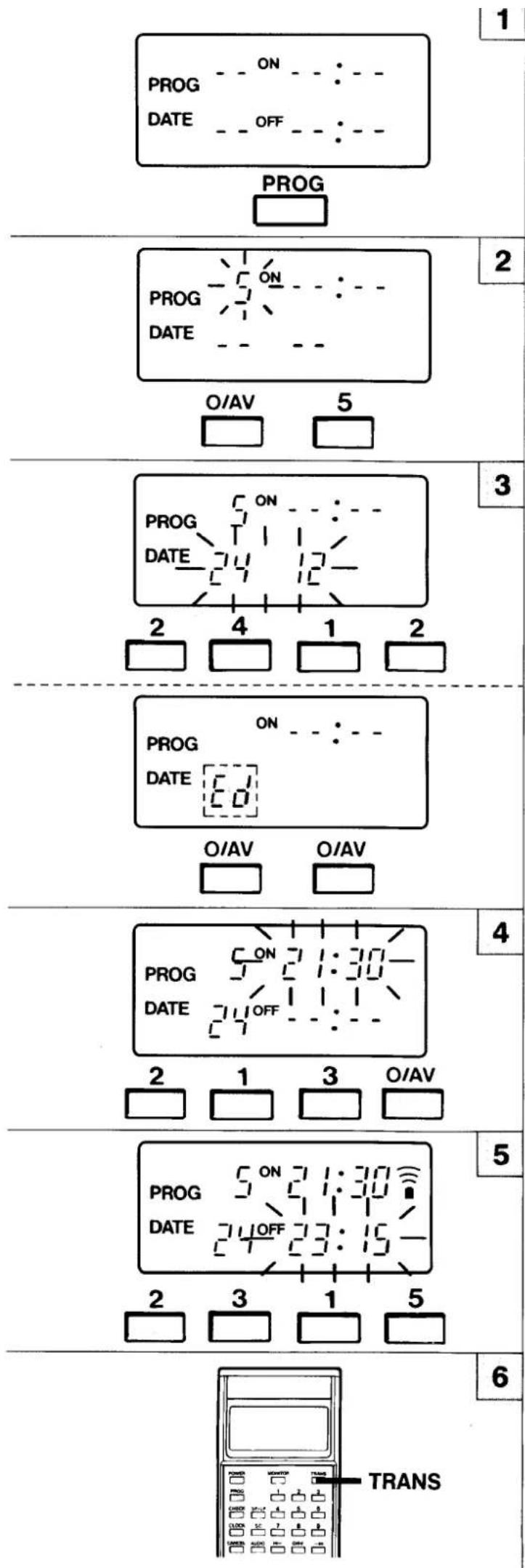
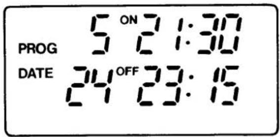
Example: Reserve channel 5 from 21:30 to 23:15 on December 24. 1990.
☐ Insert a video cassette (with erasure-prevention tab).
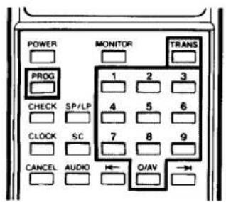
1 Press the PROG button.
2 Set the CHANNEL (position number) with numeric buttons. Example: Channel 5
3 Set the DAY with numeric buttons. Example: 24 Set the MONTH with numeric buttons. Example: 12
③ Everyday recording
To record everyday, press the "0/AV" numeric button twice. "Ed" appears on the display.
4 Set the ON-HOUR with numeric buttons. Example: 21 Set the ON-MINUTE with numeric buttons. Example: 30
5 Set the OFF-HOUR with numeric buttons. Example: 23 Set the OFF-MINUTE with numeric buttons. Example: 15
6 Press the TRANS button.
□ When programme data is sent to the VCR, the VCR automatically enters the timer standby mode and the Timer indicator (☐) lights up. □ The VCR memory can store up to 6 programmes.
ERASURE OF REMOTE CONTROL UNIT PROGRAMME DATA
Since the data for only 4 programmes can be stored in the remote control unit, if more than 4 programmes have been timer programmed, unnecessary programmes must be cancelled and setting must be performed once again.
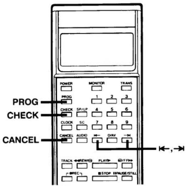
1 Press the PROG button to display on the remote control unit LCD panel the programme data to be cancelled.
2 Press the CANCEL button.
CONFIRMATION OF REMOTE CONTROL UNIT PROGRAMME DATA
1 Each time the PROG button is pressed, programme data stored in the remote control unit is shown sequentially on the remote control unit LCD panel.
☐ When the programme memory of the remote control unit is available, if the PROG button is pressed, the initial programme set mode (data input stand-by) is entered.
☐ To confirm day/month, press the → button twice during confirmation.
REVISION OF REMOTE CONTROL UNIT PROGRAMME DATA
1 Press the PROG button to display on the remote control unit LCD panel the programme data to be revised.
2 Press the → (or ←) button until the number to be changed is blinking.
3 Press the numeric buttons and correct the number.
4 After revisions are completed, press the PROG button.
CONFIRMING, REVISING OR CANCELLING PROGRAMME DATA SENT TO THE VCR
Press the CHECK button on the remote control unit while watching the VCR display. The programme data for each programme in memory is displayed in sequence. The procedure for revising and cancelling programme data is the same as that for memorizing programmes. The first step in memorizing a programme in the remote control unit is normally to press the PROG button. However, to access a programme directly as you watch the VCR display, press the CHECK button first.
NOTES ON TIMER SETTING
☐ Data for a maximum of 4 programmes can be stored in the remote control unit. Hence transmission can be performed after 4 programmes have been set in steps 1 to 5. The procedure is to call out in sequence the programmes set with the PROG button and transmit them to the VCR by the TRANS button.
☐ The timer indicator (☐) will flash to inform you if no video cassette is loaded.
☐ The timer indicator (☐) will flash 5 minutes before the starting time of each of the set programmes is reached.
☐ If an error occurs in the transmission of programme data from the remote control unit, "ER (error)" is shown on the VCR display. In this case, set the infrared emitter component of the remote control unit properly in front of the VCR remote control unit detector and transmit once again.
□ When the VCR's programme memory is full, the VCR displays "FULL".
☐ If programme setting is abandoned midway, the programme is automatically cancelled.
☐ The year is not displayed in the programme data of the remote control unit.
☐ If the same time is set for the recording start time and recording stop time, timer recording will be set to take place for 24 hours. Please note that, when a tape is inserted, recording will continue to the end of the tape.
By using the timer in this unit, you can record a source from an external audio/video unit.
At the step for setting the channel position number (for ordinary programming), cause "AU" to appear in the channel position number display and enter the external input mode into the memory.
To select the external input mode, enter "00" by pressing the 0/AV button on the remote control unit twice.
Note: You cannot turn the power to the external unit ON or OFF.
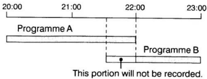
Programme priority
☐ If several recordings have been timer-programmed with overlapping recording times, then the recording with the earliest start time will be recorded first.
☐ If the start time for a second recording is reached before the programmed stop time for the first recording, the first recording will continue to the original stop time and the second recording will start after the first recording has finished.
☐ If several recordings have been programmed for the same start time on the same day, the programmed recording that was first entered has priority.
PLAYBACK
Check before starting
■ Set the TV receiver to the "VCR" programme position.
1 Insert the video cassette.
2 Press the PLAY button.
3 To stop the playback, press the STOP button.
☐ To rewind the tape, press the REW button.
☐ To advance (fast-forward) the tape, press the FF button.
FORWARD SEARCH
■ Press the FF button during playback for fast-forward operation. The picture can be viewed while the tape is advanced at a fast speed.
■ Normal playback will resume as the PLAY button is pressed.
REVERSE SEARCH
■ Press the REW button during playback for rewind operation. The picture can be viewed while the tape is rewound at a fast speed.
■ Normal playback will resume as the PLAY button is pressed.
You can perform fast forward, forward search, rewind, and reverse search operations by simply pressing the FF and REW buttons on this VCR. For example, each time the FF button is pressed, the VCR will change from fast forward to forward search, or vice-versa.
This is extremely useful when searching for a particular section of a programme.
STILL PICTURE
■ Press the PAUSE/ STILL button during playback. A still picture can be viewed.
■ Normal playback will resume when the PLAY button is pressed.
FRAME ADVANCE
■ Press the PAUSE/ STILL button during still playback. The picture will advance frame by frame. One press advances one frame.
■ Normal playback will resume when the PLAY button is pressed.
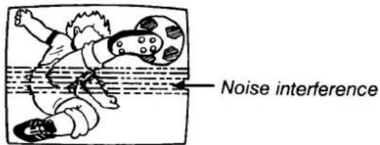
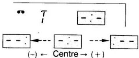
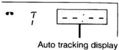
TRACKING ADJUSTMENT
If the playback picture shows noise interference, adjust the FINE TUNING/TRACKING (-, +) control buttons to minimize the noise.
Tracking condition will be displayed as follows:
flowchart
graph TD
    A["T"] --> B["Central Node"]
    B --> C["(-) ← Centre → (+)"]
    style A fill:#f9f,stroke:#333
    style B fill:#ccf,stroke:#333
    style C fill:#cfc,stroke:#333
AUTO TRACKING ADJUSTMENT
When the TRACK button of the remote control unit is pressed, adjustment to the optimum point occurs automatically.
Note:
☐ If you wish to return the tracking adjustment to its original “centre position” after having changed it, press the FINE TUNING/TRACKING “-” and “+” buttons simultaneously.
☐ If you use a poorly recorded tape, the noise level may fail to reach the optimum point. In this case, perform manual adjustment.
PICTURE SHARPNESS ADJUSTMENT
Set the PICTURE sharpness control for the picture quality that suits your tastes.
TV MONITOR FUNCTION
This function lets you view a TV programme during video playback.
■ Press and hold the MONITOR button during video playback. The TV programme on the channel that was most recently selected will be shown on the TV screen for as long as the button is held.
■ You can also monitor other external input sources if you wish. To do so, select AV input.
natural_image
Cartoon illustration of a child using a device while looking at a washing machine (no text or symbols present)Notes:
☐ During the special playback (forward search, reverse search, still picture and frame advance) the picture may contain some "noise" or vibration. But this is not a malfunction.
☐ If still picture playback is continued for about five minutes, the VCR will automatically change to stop mode in order to protect the tape from damage.
☐ If still picture moves up and down, turn the STILL V-LOCK adjustment screw. If VCR's STILL V-LOCK adjustment cannot remove this movement, also adjust the V-HOLD control of the TV receiver.
PLAYBACK Hi-Fi STEREO/ BILINGUAL PROGRAMMES
When a stereo or bilingual programme recorded on tape in hi-fi is played back, the "Hi-Fi" indicator lights up.
The sound track can be selected using the remote control unit AUDIO button.
STEREO PROGRAMMES
| Audio output indicator | Sound track |
| Left + Right channels(Hi-fi audio track) | |
| Left channel(Hi-fi audio track) | |
| Right channel(Hi-fi audio track) | |
| Doesn't light | Mono(Normal audio track) |
BILINGUAL PROGRAMMES
| Audio output indicator | Sound track |
| Main + Sub(Hi-fi audio track) | |
| Main(Hi-fi audio track) | |
| Sub channel(Hi-Fi audio track) | |
| Doesn't light | Main(Normal audio track) |
HEADPHONES
Connect the optional accessory headphones to the headphone jack.
Adjust the volume with the PHONES LEVEL control.
1
2
3
4
INDEX SEARCH FUNCTION
This convenient function enables you to use the index signal recorded at the beginning of each programme to easily select a desired programme. Data is programmed at the LCD panel of the remote control unit and transmitted to the VCR.
RECORDING OF INDEX SIGNAL
☐ The index signal is recorded automatically at the beginning of each recording. While the index is being recorded, "Id" is shown on the VCR digital display.
Note: Index signal cannot be recorded after REC PAUSE.
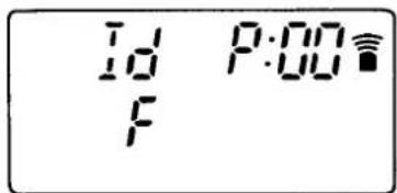
INDEX SCAN SEARCH
This feature enables each programmes with index signals recorded to be played back for 5 seconds consecutively during search.
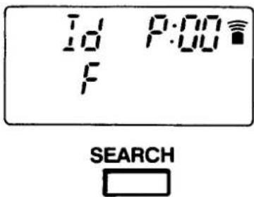
1 Press the SEARCH button once during the STOP or PLAY mode.
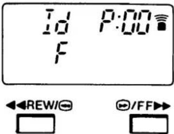
2 Press the FF or REW button depending upon the scanning direction.
The "F" indication on the LCD panel indicates fast forward, and the "r" indication indicates rewind.
The "F" indication appears first, so this step can be skipped for scanning in the fast-forward mode.
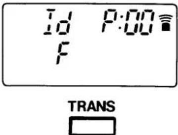
3 Press the TRANS button.
☐ FF or REW starts and each time an index signal is found, the tape is played back for about 5 seconds.
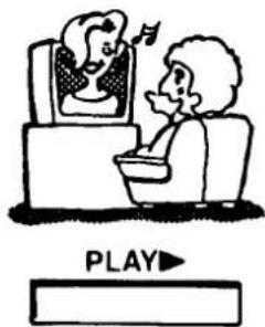
4 Press the PLAY button when the desired programme is seen.
To return the LCD panel to the initial display, press the SEARCH button.
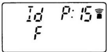
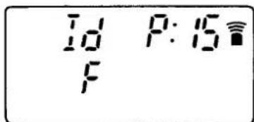
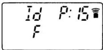
INDEX SEARCH
This feature enables automatic search for and playback of a programme who's INDEX number is known.
1 Press the SEARCH button once during STOP or PLAY mode.
2 Press the number using the numeric buttons to indicate how many programmes before or after the present one you wish to watch.
Example: 15
□ Any index number up to "99" can be designated.
☐ Press the CANCEL button when revising.
3 Designate the direction of search by pressing the FF button or the REW button.
The "F" indication on the LCD panel indicates the fast-forward direction, and the "r" indication indicates the rewind direction.
This step can be skipped for search in the fast-forward direction.
4 Press the TRANS button.
☐ FF or REW starts and when the designated index number is found, playback starts automatically.
Notes:
☐ If you insert the index signal in the Playback mode, the audio will not be heard while the index signal is being recorded.
☐ In the playback mode you cannot insert an index signal on a video cassette which does not have an erasure-prevention tab or at non-recorded part of the tape.
☐ If you record or erase and index signal to or from a tape recorded using another VCR, the video programme at that point may be disturbed or it may be impossible to search it.
To return the LCD panel to the initial display, press the SEARCH button.
1
SEARCH
2


3


4

SEARCH

1


2


3
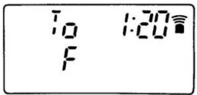

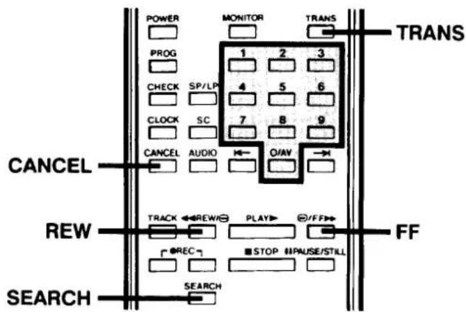
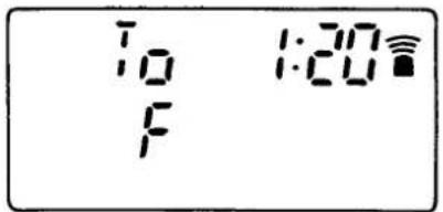
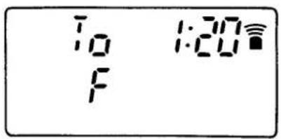
GO TO SEARCH FUNCTION
This feature enables forward and reverse search with reference to tape playing time.
1 Press the SEARCH button twice during STOP or PLAY mode.
2 Input the time difference between the desired scene and present tape position, using the numeric buttons.
Example: 1 hour 20 minutes
☐ Press the CANCEL button when revising.
3 Designate the direction of search by pressing the FF button or the REW button.
The "F" indication on the LCD panel indicates the fast-forward direction, and the "r" indication indicates the rewind direction.
This step can be skipped for search in the fast-forward direction.
4 Press the TRANS button.
☐ Tape will advance at fast speed to the desired scene and then starts playback.
Note: The error between the designated time and the counter reading is about ± 30 seconds.
To return the LCD panel to the initial display, press the SEARCH button.
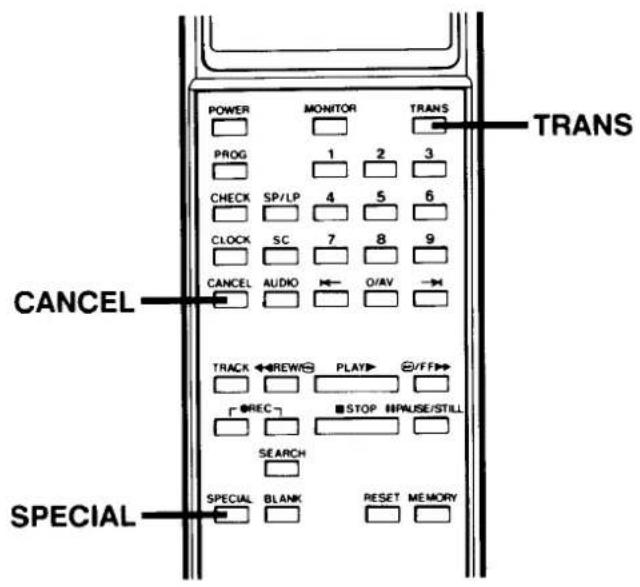
SPECIAL CODE FUNCTION
For your convenience, this VCR has various special functions using SPECIAL CODE.
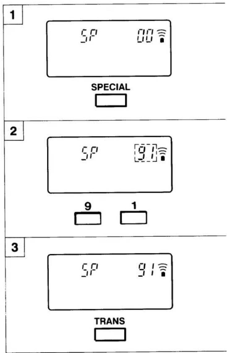
1 Press the SPECIAL button.
2 Input 2-digit SPECIAL CODE with numeric buttons.
Example: "91" (ENDLESS PLAY)
☐ Press the CANCEL button when revising.
3 Press the TRANS button.
Upon completion of the aforementioned fundamental operations, special functions can be implemented by inputting each special code through step 2.
“02”—KEY LOCK: Prevents all operation of the VCR.
1 Transmit SPECIAL CODE "02". When the KEY LOCK is engaged, the "j" indicator is shown on the display.
② To cancel the lock function, transmit "02" once again.
Please note that when you transmit SPECIAL CODE 02 (KEY LOCK) to the VCR, all VCR control buttons become inoperative. It is recommended that you turn off the VCR power before transmitting SPECIAL CODE 02.
"91"— ENDLESS PLAY: Plays back the tape repeatedly from beginning to end (from tape start to "0H00M00s" in case of counter memory).
1 Insert the cassette tape, and transmit SPECIAL CODE "91". Playback starts once the tape has been rewound to the beginning.
To return the LCD panel to the initial display, press the SPECIAL button.
REPAIRS
This VCR is a precision instrument and treated with care, will provide years of satisfactory performance. However, in the event of difficulty, the owner is advised not to attempt to make repairs or open the cabinet. Servicing should always be referred to your SANYO Authorized SERVICE AGENT.
TROUBLESHOOTING
This VCR is highly sophisticated. It is shipped from the factory after having been checked and adjusted under the most rigid quality control and inspection system. Should problems occur, check the following points.
| Symptom | Check points |
| No power | The power cord is disconnected. |
| No off the air programmes | Are the connections between your VCR and TV correct.The tuning of the TV receiver does not correspond to the RF channel presetting of the VCR. |
| Off the air reception on the VCR is poor | |
| No recording | The erasure-prevention tab on the cassette has been removed. |
| Timer recording is not possible | The starting day and time have not been set correctly.The clock time is not set correctly.There has been a power interruption. |
| Playback picture does not appear | The tuning of the TV receiver does not correspond to the RF channel presetting of the VCR. |
| Interference on playback picture | Adjust the TRACKING control.Dust and dirt on video heads.Take the VCR to an Authorized Service Station or dealer. |
SPECIFICATIONS
General
| Video format: | VHS PAL |
| Television system: | CCIR: 625 lines, PAL colour signals |
| Recording system: | Rotary two heads helicalscan system |
| Audio recording system | VHS hi-fi system(2 channels), (Normal audio track is monaural) |
| Tape speed: | SP: 23.39 mm/secLP (hi-fi): 11.70 mm/sec (Hi-Fi audio only) |
| Recording time: | SP: 240 minutes with E-240 cassetteLP (hi-fi): 480 minutes with E-240 cassette (Hi-Fi audio only) |
| Tuner input: | UHF: 21–69 |
| RF converter: | Built-in UHF converter |
| Converter output: | On channel 32 – 42 |
| Timer indication: | 24 hour indication |
| Power failure backup: | Approx. one hour |
| Timer recording | 1 year 6 programmes with every day function |
| Power requirement: | AC 240 V ± 10%, 50 Hz |
| Dimensions(W x H x D): | 420 x 79 x 360 mm |
| Weight: | Approx. 6 kg |
| Power consumption: | 30 W |
Electronic characteristics
| Video input level: | 0.5–2.0 Vp-p |
| Video input impedance: | 75 ± 5 ohms |
| Video outputlevel: | 1.0 ± 0.2 Vp-p |
| Video output impedance: | 75 ± 5 ohms |
| Audio inputAUDIO/VIDEO(21-pin): | -3.8 dBs, more than 10 kohms |
| AUDIO IN (RCA): | -3.8 dBs, more than 10 kohms |
| Audio outputAUDIO/VIDEO(21-pin): | -3.8 dBs, less than 1 kohm |
| AUDIO OUT (RCA): | -3.8 dBs, less than 1 kohm |
| Video S/N: | Luminance: more than 43 dB |
| Resolution: | Colour: more than 240 lines |
VHS hi-fi audio
| Frequency response | 20 Hz – 20,000 Hz |
| Dynamic response | More than 90 dB |
| Wow and flutter | Less than 0.005% (WRMS) |
| Channel separation | More than 60 dB |
Remote control unit
| Power requirements: | 3V (two “AA” size, 1.5-volt batteries) |
Accessories
| Instruction manual | 1 |
| Antenna output cable | 1 |
| Remote control unit | 1 |
Appearance and specifications are subject to change without notice.
WARRANTY TO CUSTOMER
Sanyo Marubeni (UK) Ltd. (the Company) warrants to the initial retail purchaser that if this equipment is or becomes defective and that, in the opinion of the Company, the defect is due to faulty material or workmanship the Company will, for a period of 12 calendar months from the date of sale to the original purchaser repair or replace, at its sole option, free of charge, any such defective component part of the equipment, always provided that:-
- The equipment has at all times been used in accordance with the operating instructions issued by the Company, and has not been connected to an electrical mains supply for which it has not been adjusted.
- Accidental damage, or damage caused by negligence of misuse by the user, including leakage from exhausted batteries, is specifically excluded.
- Unauthorised repairs, or any modification to the equipment which has not been expressly approved by the Company, shall render this warranty null and void.
- Failure due to fair wear and tear of any item, such as batteries, record playing styli, and tape recording, playback and erase heads and head cleaning is specifically excluded.
This warranty is not transferable and is only applicable within the United Kingdom (and the Republic of Ireland). Nothing in this express warranty affects the statutory rights available to the purchaser of this equipment.
Note: This warranty supersedes any other form of guarantee that may inadvertently have been enclosed with or attached to the product.
DearCustomer
Thank you for buying Sanyo. This equipment should give you many years of pleasure and faithful service but in the event that a fault occurs, the following notes for your guidance may be helpful:-
- PLEASE RETAIN YOUR PURCHASE RECEIPT WHICH WILL BE REQUIRED FOR SERVICE DURING WARRANTY.
- If your Sanyo equipment proves faulty during the period of guarantee, take it or send it back to the dealer who originally supplied it together with this guarantee and the proof of purchase. We have made arrangements with our approved dealers under which they will carry out in guarantee service repairs on our behalf. In this way, we hope to reduce to a minimum the amount of time you will be without your equipment.
- If for some reason it is impossible to return the equipment to the original supplier, please contact our Service Administration Department at the address below for further advice.
- Should the equipment require servicing after the expiry of the guarantee period, take or send it to the original supplier or any other Sanyo dealer. He will be pleased to give you a quotation for the repair. If you are in any doubt about what to do, write to us at the address below or telephone:
Service Administration Department, Sanyo Marubeni (UK) Limited.
Sanyo House Otterspool way, Watford, Hertfordshire WD2 8JX Tel: Watford 246363
SANYO