MBR150 - Empfänger APART - Kostenlose Bedienungsanleitung
Finden Sie kostenlos die Bedienungsanleitung des Geräts MBR150 APART als PDF.

| Produkttyp | Empfänger |
| Marke | APART |
| Modell | MBR150 |
| Abmessungen (B x H x T) | 430 mm x 150 mm x 320 mm |
| Gewicht | 8 kg |
| Stromversorgung | 230 V ~ 50 Hz |
| Leistungsaufnahme | 150 W |
| Ausgangsleistung (RMS) | 2 x 100 W an 8 Ohm |
| Frequenzgang | 20 Hz - 20 kHz ± 0,5 dB |
| Klirrfaktor (THD) | < 0,05 % |
| Eingänge | 3x Cinch, 1x optisch, 1x koaxial |
| Ausgänge | 1x Cinch Pre-Out, 1x Kopfhörer |
| Lautsprecheranschlüsse | Schraubklemmen |
| Unterstützte Impedanz | 4 - 16 Ohm |
| Fernbedienung | ja (IR) |
| Gehäusematerial | Metall, schwarz lackiert |
| Betriebstemperatur | 0 °C bis 40 °C |
| Lagertemperatur | -20 °C bis 60 °C |
| Zubehör | Netzkabel, Bedienungsanleitung, Fernbedienung |
| Reinigung | Mit trockenem, fusselfreiem Tuch abwischen |
| Sicherheitshinweis | Gerät vor Feuchtigkeit schützen, Netzstecker ziehen vor Reinigung |
| Reparatur | Nur durch qualifiziertes Fachpersonal |
| Garantie | 2 Jahre |
Häufig gestellte Fragen - MBR150 APART
Benutzerfragen zu MBR150 APART
0 Frage zu diesem Gerät. Beantworten Sie die, die Sie kennen, oder stellen Sie Ihre eigene.
Eine neue Frage zu diesem Gerät stellen
Laden Sie die Anleitung für Ihr Empfänger kostenlos im PDF-Format! Finden Sie Ihr Handbuch MBR150 - APART und nehmen Sie Ihr elektronisches Gerät wieder in die Hand. Auf dieser Seite sind alle Dokumente veröffentlicht, die für die Verwendung Ihres Geräts notwendig sind. MBR150 von der Marke APART.
BEDIENUNGSANLEITUNG MBR150 APART

SOUNDBLOCK with extra features


SOUNDBLOCK with extra features
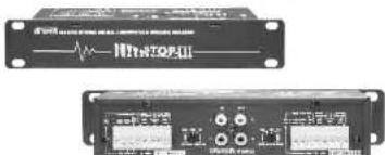
MBR-150
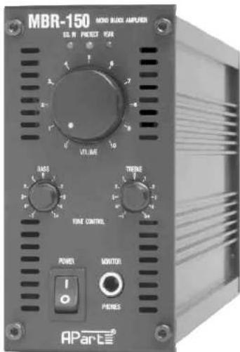
OWNER'S MANUAL

SOUNDBLOCK with extra features
SOUNDBLOCK with extra features
1. Protection Led:
The Protection Led illuminates RED
when the amplifier is overheated or
when a shorted load or DC is
detected on the amplifier output.
The amplifier shall reset itself when
the problem is solved.
- Signal LED indicator
The LED will light up green when
the input detects audio signal.
- Peak LED/limiter
The red LED illuminates if the input signal of the amplifier to high. Occasional blinking of this LED
is acceptable, but if it remains (on) or more than intermittently, then you should lower the input level or reduce the output
level of the preceding component to avoid audible distortion.A built-in limiter will prevent excessive RMS clipping.
If you want to bypass the limiter function, then disconnect JP1 (left channel) and JP2 (right channel) inside.
Please contact a qualified technician.
4A. Level control
This volume knob is used to adjust the level of the output to the speakers.
This control operates before the up/down remote volume
4B. Tone controls
With these tone controls, you can adjust the sound response of your system.
- Power switch
switch to 'ON' position to turn power on, and to 'OFF' to turn power off. (SEE ALSO 13)
- Monitor Jack
A stereo headphone can be inserted to this Jack for monitoring the amplifier output.
- Unbalanced input cinch
Cinch-RCA connectors for applying the input signal for the left and right channel.
- Speaker output terminals connecting the speaker system
The minimum load is 2 ohms.
Of course, higher loads are acceptable. 4 ohm=min. 4 pcs. of 16 ohm speakers wired
in parallel or max. 2 pcs. of 8 ohm speakers wired in parallel
- AC outlet un-switched/AC input
Use AC cord connect to the AC input to a AC socket.
Use the AC outlet to power other modules (with the MB-AC link cable) or to other associated equipment.
AC voltage is always present as long as the amplifier is connected to the AC voltage source.
- AC fuse
It the fuse is blown, please disconnect the power cord, and replace fuse by the same value 3.15 AT
of the SLOW BLOW type. If the fuse blows again, then contact your dealer for further servicing.
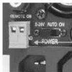
- Remote 'Power-on' system
All these features can be used only with the frontal Power switch (7) in the "ON" position.
- switch in left position '5-24V': The amplifier shall be activated when an external control signal
between 5 and 24 Vdc is applied on the 2 screw terminals
- switch in middle position 'AUTO'. The amplifier shall be activated when any audio signal is present
at the input. The sensitivity of this sensing circuit can be adjusted by the trimmer R160 inside
(by a qualified technician only). When the audio signal is away, then the amplifier will turn itself OFF
after several minutes of silence
- switch in right position 'ON'. The amplifier can be switched ON and OFF as usual namely by the frontal Power switch(7).
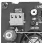
- Remote Volume control
Screw connector for the connection of the remote volume control. For a more details see page 3
- Low cut=high pass filter
When this button is pushed in, then the Hi Pass filter's frequency is set at 100HZ.
100HZ is used when you connect small speakers which are not able to reproduce low frequencies.
- Link L+R
When set at "L+R", the red and white RCA cinch inputs are mixed (stereo into mono).
When set at "Link", both red and white cinch are connected in parallel for easy linking the input signal.
- Loudness switch
Push this button to to enhance the low & high frequencies.
It's recommended to use this feature only at low power settings.

SOUNDBLOCK with extra features
SAFETY INFORMATION
- Read all documentation before operating your equipment. Retain all documentation for future reference.
- Save the carton and packing material even if the equipment has arrived in good condition. Should you ever need to ship the unit, use only the original factory packing.
- Do not spill water or other liquids into or on the unit.
- Make sure power outlets conform to the power requirements listed on the back of the unit.
- Do not use the unit if the electrical power cord is frayed or broken.
• Always operate the unit with the AC ground wire connected to the electrical system ground. - Have gain controls on amplifiers turned down during power-up to prevent speaker damage if there are high signal levels at the inputs.
- Do not connect the inputs / outputs of amplifiers or consoles to any other voltage source, such as a battery, mains source, or power supply, regardless of whether the amplifier or console is turned on or off.
- Power down & disconnect units from mains voltage before making connections.
- Do not use the unit near stoves, heat registers, radiators, or other heat producing devices.
- Do not block fan intake or exhaust ports. Do not operate equipment on a surface or in an environment which may distort the normal flow of air around the unit. If the unit is used in an extremely dusty or smoky environment, the unit should be periodically "blown free" of dust.
- Do not remove the cover. Removing the cover will expose you to potentially dangerous voltages.
- Do not drive the inputs with a signal level greater than that required to drive equipment to full output.
- Do not run the output of any amplifier back into another input.
- Do not ground the red output terminal, never connect a red output terminal to another red output terminal.
• In case of mal-function this device should be serviced by qualified service personnel only.
CAUTION
TO REDUCE THE RISK OF ELECTRIC SHOCK DO NOT REMOVE COVER OR BACK
NO USER-SERVICEABLE PARTS INSIDE SERVICING ONLY FOR QUALIFIED PERSONNEL


SOUNDBLOCK with extra features
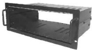
OPTIONS
- MB19 : 4 unit high 19" rack chassis ; up to 6 modules.
natural_image
Exterior view of a black metal enclosure or housing unit (no text or symbols visible)- MB-BL : Front + Rear blindpanel set for the empty spaces.
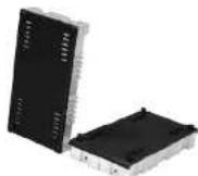
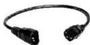
• MB-AC : Short AC power cord linking cable 230 Vac.
- BUZZ-STOP II : to avoid ground loops.
natural_image
Two electronic devices with visible ports and connectors, no readable text or symbols

SOUNDBLOCK with extra features
SPECIAL FEATURES
- Remote power ON
2-pole Euro Block connector.
If a DC voltage (5-24 Volt) is applied the amplifier switches ON.
Caution
- When connecting the DC voltage, take care of the correct polarity.
- Switch the remote power switch (13) to the left position (5-24V).
- Switch the frontal power switch (7) in the ON position
• Remote volume control
3-pole Euro Block connector.
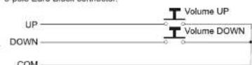
- The "up-down" switch can be any kind of switch you like. However, DO NOT apply any external voltage.

- The turning speed of the cooling fan is related to the temperature of the amplifier. When the amplifier is cold it's normal that the fan doesn't turn. Only if a lot of output-power is requested the fan will turn.
| Technical specifications | MBR150 |
| Power Rated / Max | |
| 2 ohm | 1 X 170 / 200 Watt |
| 4 ohm | 1 X 150 / 180 Watt |
| 8 ohm | 1 X 100 / 140 Watt |
| Input Sensitivity | 0.775 Vrms/MAX input level +14dBV |
| Input impedance | 20 Kohm |
| Freq. Response | 20hz - 30KHz |
| Total harm. distortion | <0.02% |
| Damping factor | (4 ohm) >300 |
| Power consumption | 300 VA MAX |
| Dimensions (H x W x D): | 70 X 140 X 335 MM |
| Weight | Net, 2.8 Kg |
- Due to the built-in limiter, some values may differ from the specs listed above. Due to our continuous research and development, the product specifications may change without prior notice at any time.

SOUNDBLOCK with extra features

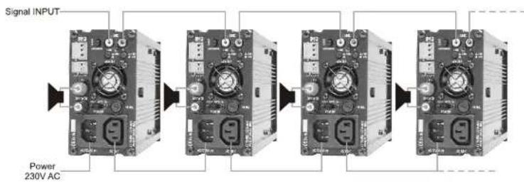
BASIC connection of the amplifiers
flowchart
graph LR
    A["Signal INPUT"] --> B["Module 1"]
    B --> C["Module 2"]
    C --> D["Module 3"]
    D --> E["Module 4"]
    E --> F["Output"]
    style A fill:#f9f,stroke:#333
    style B fill:#ccf,stroke:#333
    style C fill:#ccf,stroke:#333
    style D fill:#ccf,stroke:#333
    style E fill:#ccf,stroke:#333
    style F fill:#ccf,stroke:#333
+Push the LINK button (16).
- Link the stereo input signal to all the amplifiers
Connecting up to 6 amplifiers to one source (g.e. cd player) isn't a problem.
If you want to connect more then 6 amplifiers you need a pre-amplifier (Pm7400 MKII).
or other pro-audio equipment.
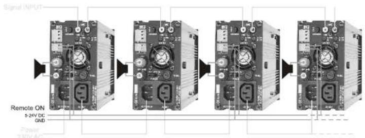
- With this feature you can switch ON or OFF the amplifier from a distance, using a low voltage power supply.
REMOTE-ON connection of the amplifiers
flowchart
graph LR
    A["Signal INPUT"] --> B["Stage 1"]
    B --> C["Stage 2"]
    C --> D["Stage 3"]
    D --> E["Stage 4"]
- It's possible to parallel-connect all the remote-ON contacts.
In this way you can remote switch (ON or OFF) all the amplifiers in one time. - You can use any DC power supply from 5 to 24Volt DC to switch ON the amplifiers.
- Remember to put the power switch (13) on the 5-24V position if you want to use the Remote-ON feature.
- NOTICE: watch the polarity of the DC signal when connecting the amplifiers.

SOUNDBLOCK with extra features
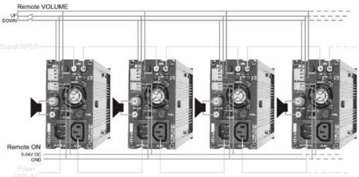
REMOTE VOLUME & ON connection of the amplifiers
- With the REMOTE-ON feature you can change the volume (up and down). The only thing's you need are two push-button's and a 3-wire.
flowchart
graph LR
    A["Remote VOLUME"] --> B["1"]
    B --> C["2"]
    C --> D["3"]
    D --> E["4"]
    E --> F["5"]
    style A fill:#f9f,stroke:#333
    style B fill:#ccf,stroke:#333
    style C fill:#cfc,stroke:#333
    style D fill:#fcc,stroke:#333
    style E fill:#cff,stroke:#333
    style F fill:#ffc,stroke:#333
- It's possible to parallel connect all the remote volume contacts, in this way you can change all the volumes in one time.
• The volume control knob on the front-panel (4a) is the master. So you can use this control to preset the max. volume in each
zone, in this way the amplifier can't play louder (using the remote volume control) then the preset level on the front-panel.
• The amplifier has a volume memory, if you switch off the amplifier and back on the level will be the same as before.
Hum & Buzz
- If 'Hum' or Buzz' occurs when connecting different inputs, then this is often caused by 'GROUND or EARTH LOOPS'.
Inside you can disconnect Jp3 to break this ground loop.
Please contact a qualified technician to do this.