
TC25 - Stregkodescanner ZEBRA - Gratis brugsanvisning og manual
Find enhedens vejledning gratis TC25 ZEBRA i PDF-format.


Brugerspørgsmål om TC25 ZEBRA
0 spørgsmål om dette apparat. Besvar dem du kender, eller stil dit eget.
Stil et nyt spørgsmål om dette apparat
Download vejledningen til din Stregkodescanner i PDF-format gratis! Find din vejledning TC25 - ZEBRA og tag din elektroniske enhed tilbage i hånden. På denne side er alle dokumenter nødvendige for brugen af din enhed offentliggjort. TC25 af mærket ZEBRA.
BRUGSANVISNING TC25 ZEBRA
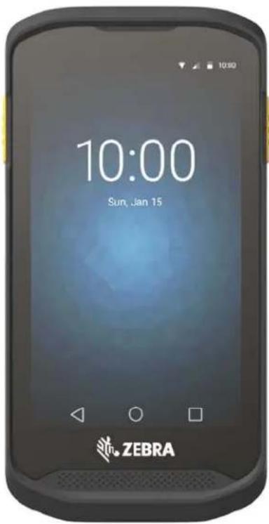
TC25
Touch Computer

natural_image
Abstract blue logo with white geometric shapes (no text or symbols)ZEBRA
Quick Start Guide
This guide applies to model numbers: TC25AJ, TC25BJ and TC25CJ.
Copyright
© 2017 ZIH Corp. and/or its affiliates. All rights reserved. ZEBRA and the stylized Zebra head are trademarks of ZIH Corp., registered in many jurisdictions worldwide. All other trademarks are the property of their respective owners.
COPYRIGHTS & TRADEMARKS: For complete copyright and trademark information, go to www.zebra.com/copyright.
WARRANTY: For complete warranty information, go to www.zebra.com/warranty.
END USER LICENSE AGREEMENT: For complete EULA information, go to www.zebra.com/eula.
Terms of Use
- Proprietary Statement This manual contains proprietary information of Zebra Technologies Corporation and its subsidiaries (“Zebra Technologies”). It is intended solely for the information and use of parties operating and maintaining described herein. Such proprietary information may not be used, reproduced, or disclosed to any other parties for any other purpose without the express, written permission of Zebra Technologies.
- Product Improvements Continuous improvement of products is a policy of Zebra Technologies. All specifications and designs are subject to change without notice.
- Liability Disclaimer Zebra Technologies takes steps to ensure that its published Engineering specifications and manuals are correct; however, errors do occur. Zebra Technologies reserves the right to correct any such errors and disclaims liability resulting therefrom.
- Limitation of Liability In no event shall Zebra Technologies or anyone else involved in the creation, production, or delivery of the accompanying product (including hardware and software) be liable for any damages whatsoever (including, without limitation, consequential damages including loss of business profits, business interruption, or loss of business information) arising out of the use of, the results of use of, or inability to use such product, even if Zebra Technologies has been advised of the possibility of such damages. Some jurisdictions do not allow the exclusion or limitation of incidental or consequential damages, so the above limitation or exclusion may not apply to you.
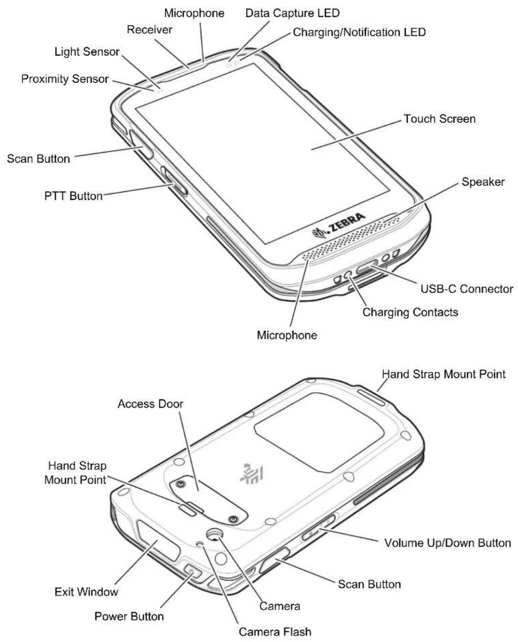
Features
Installing a microSD Card
The microSD card slot provides secondary non-volatile storage. The slot is located under the access door. Refer to the documentation provided with the card for more information, and follow the manufacturer's recommendations for use.

CAUTION Follow proper electrostatic discharge (ESD) precautions to avoid damaging the microSD card. Proper ESD precautions include, but are not limited to, working on an ESD mat and ensuring that the operator is properly grounded.
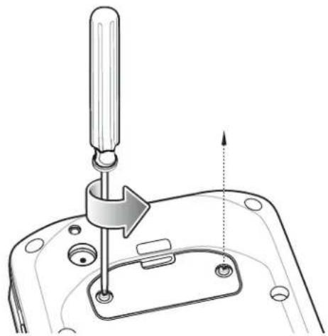
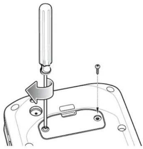
- Using a #0 Phillips screwdriver, remove two screws securing the access door.
natural_image
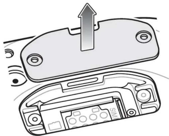
Technical line drawing of a mechanical component with a screwdriver inserted, showing a tool interacting with a base (no text or symbols)- Remove access door.
natural_image
Diagram showing a device with an upward arrow pointing to a component, and a close-up of internal components (no text or symbols)- Align the microSD card with the SD card slot.
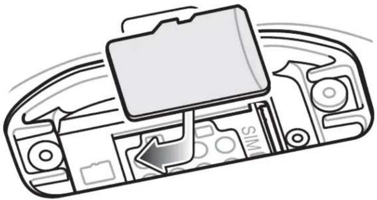
natural_image
Diagram of a device with a folder and SIM logo, showing internal components without any readable text or symbols.- Push the microSD card into the SD card slot.
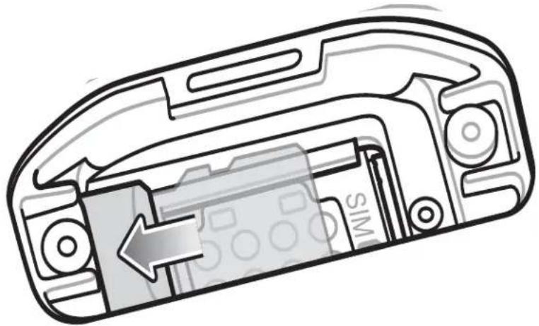
natural_image
Cross-sectional diagram of a device casing showing internal components and a directional arrow (no text or symbols)- If installing a SIM card, skip to Installing SIM Card on page 6
- Replace the access Door.
- Secure the access door using the two screws.

CAUTION Access door must be replaced and securely seated to ensure proper device sealing.
- Re-install the access door.
natural_image
Technical line drawing of a mechanical assembly with a tool inserted into a housing (no text or symbols)Installing SIM Card

NOTE Only use a nano SIM card.
Only use nano SIM cards that meet the ESTI TS102.221 standard for nano SIM cards, form factor 4FF (0.67 mm thick). Do not use SIM cards that are cut from thicker mini or micro SIM cards.

CAUTION For proper electrostatic discharge (ESD) precautions to avoid damaging the SIM card. Proper ESD precautions include, but not limited to, working on an ESD mat and ensuring that the user is properly grounded.
To install a SIM card:
- Using a #0 Phillips screwdriver, remove two screws securing the access door.
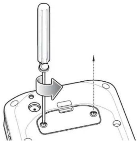
natural_image
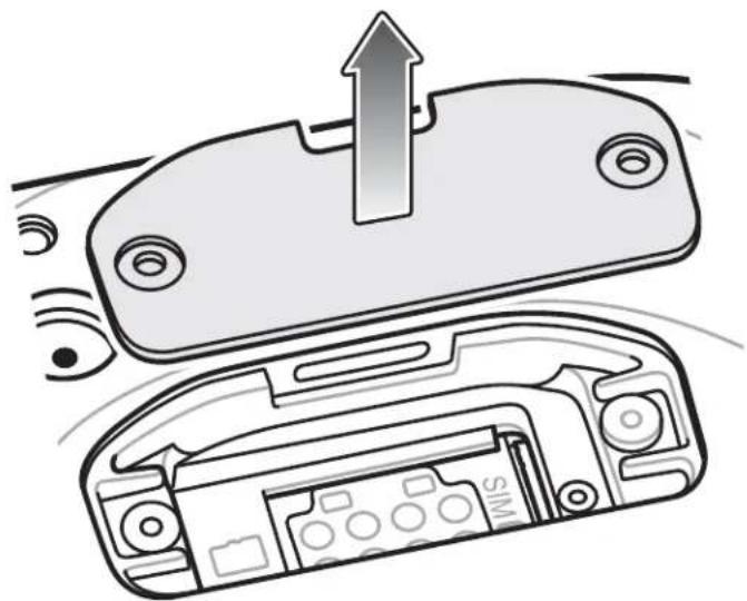
Technical illustration of a mechanical assembly with a tool inserted into a housing (no text or symbols)- Remove access door.
natural_image
Diagram of a device showing an open lid with a handle and internal components, no text or symbols present.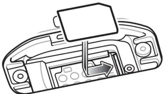
natural_image
Diagram of a computer case with internal components and directional arrow (no text or symbols)- Align the SIM card with the SIM slot.
natural_image
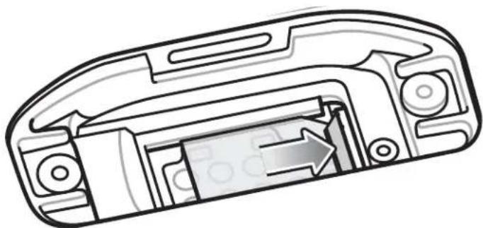
Cross-sectional diagram of a device casing showing internal components and a directional arrow (no text or symbols)- Push the SIM card into the SIM slot.

CAUTION Access door must be replaced and securely seated to ensure proper device sealing.
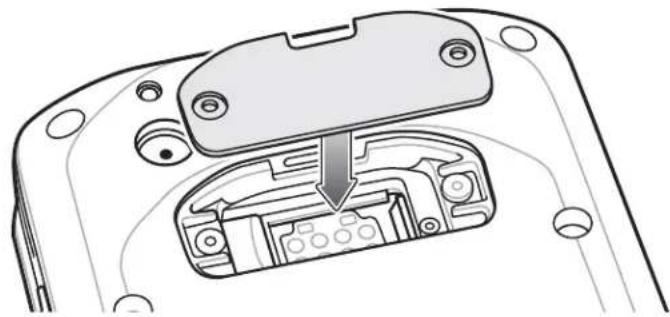
- Replace the Access Door.
TC25 Touch Computer Quick Start Guide
natural_image
Diagram of a device's internal structure showing a connector with an arrow pointing to a component (no text or symbols present)- Secure door.
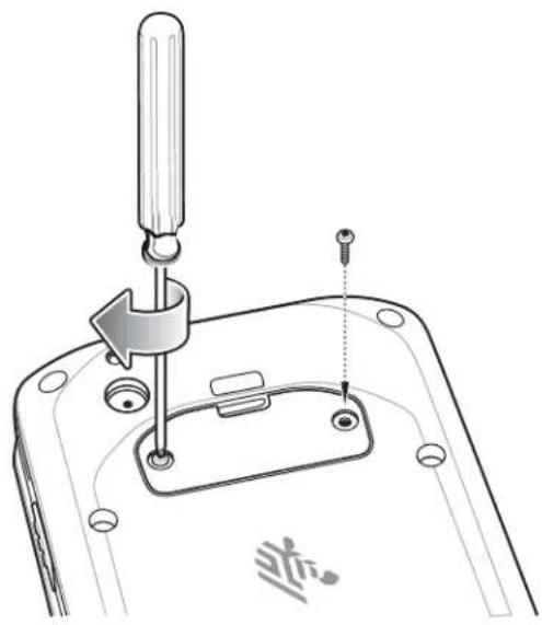
natural_image
Technical diagram of a mechanical device with a screwdriver inserted into a housing (no text or symbols)Charging the TC25
Use one of the following accessories to charge the TC25.
Table 1 Charging and Communication
| Description Part Number | Charging Communication | ||||
| Battery USB Ethernet | |||||
| 1-Slot Charge Only Cradle CRD-TC2X-BS1CO-01 Yes No | No | ||||
| 1-Slot Ethernet Only Cradle CRD-TC2X-SE1ET-01 Yes Yes | With Optional | Module | |||
| 5-Slot Charge Only Cradle CRD-TC2X-SE5CO-01 Yes No | No | ||||
| USB-C Cable CBL-TC2X-USBC-01 Yes Yes | No | ||||
Charging the TC25
To charge the TC25:
- To charge the internal battery, connect the charging accessory to the appropriate power source.
- Insert the TC25 into a cradle or attach to a cable. The TC25 turns on and begins charging. The Charging/Notification LED blinks amber while charging, then turns solid green when fully charged.
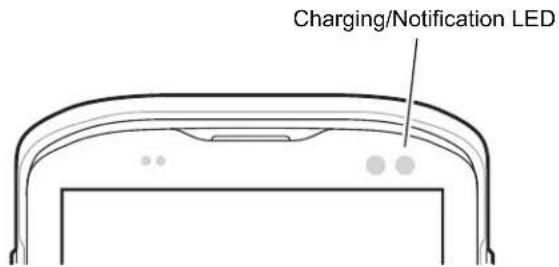
The internal battery charges to 90% in approximately four hours and from fully depleted to 100% in approximately five hours.

NOTE In many cases the 90% charge provides plenty of charge for daily use. A full 100% charge lasts for approximately 10 hours of use.
Use only Zebra charging accessories and batteries. Charge batteries at room temperature with the TC25 in sleep mode.
Charge batteries in temperatures from 0^ C to 40^ C ( 32^ F to 104^ F). The device or cradle always performs battery charging in a safe and intelligent manner. At higher temperatures (e.g. approximately +37^ C ( +98^ F)) the device or cradle may for small periods of time alternately enable and disable battery charging to keep the battery at acceptable temperatures. The device and cradle indicates when charging is disabled due to abnormal temperatures via its LED.
Table 2 Charging/Notification LED Charging Indicators
| State LED Indication | ||
| Off TC25 is not charging. TC25 is not inserted correctly in the cradle or connected to a power source. Charger/cradle is not powered. | ||
| Slow Blinking Amber(1 blink every 4 seconds) |  | TC25 is charging. |
| Slow Blinking Red(1 blink every 4 seconds) |  | TC25 is charging but the battery is at end of useful life. See system administrator. |
| Solid Green Charging complete |  | |
| Solid Red Charging complete |  battery is at end of useful life. See system administrator. battery is at end of useful life. See system administrator. | |
| Fast Blinking Amber(2 blinks/second) |  | Charging error, e.g.:Temperature is too low or too high.Charging has gone on too long without completion (typically 10 hours). |
 | ||
| Fast Blinking Red(2 blinks/second) | Charging error but the battery is at end of useful life., e.g.:Temperature is too low or too high.Charging has gone on too long without completion (typically 10 hours).See system administrator. | |
Charge batteries in temperatures from 0^ C to 40^ C ( 32^ F to 104^ F). The device or cradle always performs battery charging in a safe and intelligent manner. At higher temperatures (e.g. approximately +37^ C ( +98^ F)) the device or cradle may for small periods of time alternately enable and disable battery charging to keep the battery at acceptable temperatures. The device and cradle indicates when charging is disabled due to abnormal temperatures via its LED.
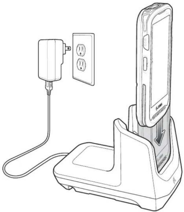
1-Slot Charge Only Cradle
The 1-Slot Charge Only Cradle provide 5 VDC for charging:
- TC25 battery
• Extended Power Pack
• TC25 and Extended Power Pack
• TC25 with Trigger Handle.
natural_image
Line drawing of a mobile phone charging station with a power plug and two outlets, no text or symbols present1-Slot Ethernet Cradle
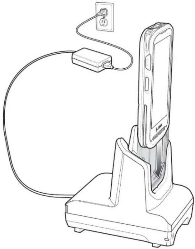
The 1-Slot Ethernet Cradle:
• Provides 5 VDC for charging:
- TC25 battery
- Extended Power Pack
• TC25 and Extended Power Pack
• TC25 with Trigger Handle.
- Provides USB communication.
- Provides Ethernet and USB communication using the USB/Ethernet Adapter.
natural_image
Line drawing of a mobile phone charger with cable and power outlet, no text or symbols present5-Slot Charge Only Cradle
The 5-Slot Charge Only Cradle provides 5 VDC for charging:
- TC25 battery
• Extended Power Pack
• TC25 and Extended Power Pack
• TC25 with Trigger Handle.
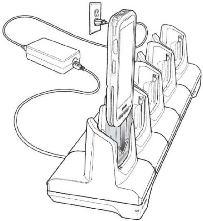
natural_image
Line drawing of a battery charging station with an attached charger and cable (no text or symbols)USB Cable
The Zebra USB Cable provides 5 VDC for charging:
- TC25 battery
• Extended Power Pack
• TC25 and Extended Power Pack.

NOTE Use only Zebra USB-C cable for charging.

Scanning
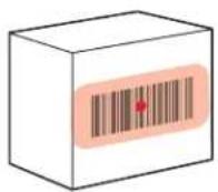
To read a bar code, a scan-enabled application is required. The TC25 contains the DataWedge application that allows the user to enable the imager, decode the bar code data and display the bar code content.
- Ensure that an application is open on the TC25 and a text field is in focus (text cursor in text field).
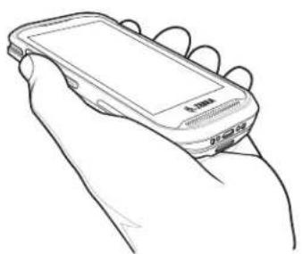
- Point the exit window on the top of the TC25 at a bar code.
natural_image
Line drawing of a hand holding a mobile phone with a screen (no text or symbols visible)- Press and hold the scan button.
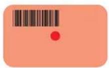
On devices with SE4710 imager, the red LED aiming pattern turns on to assist in aiming.
On devices with SE2100 imager, the white LED aiming pattern turns on to assist in aiming.

NOTE Picklist Mode is only available on TC25 with SE4710 imager.
When the TC25 is in Picklist mode, the imager does not decode the bar code until the crosshair or aiming dot touches the bar code.
- Ensure the bar code is within the area formed by the aiming pattern. On devices with SE4710 imager, the aiming dot is used for increased visibility in bright lighting conditions.

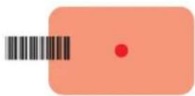

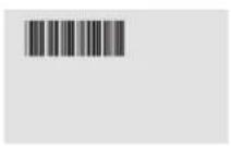

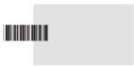

SE2100 Decode ModeSE4710 Decode Mode
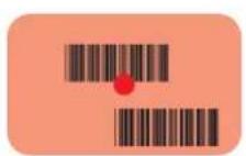

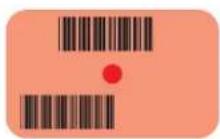

SE4710 Picklist Mode
- The Data Capture LED lights green and a beep sounds, by default, to indicate the bar code was decoded successfully.
- Release the scan button.

NOTE Imager decoding usually occurs instantaneously. The TC25 repeats the steps required to take a digital picture (image) of a poor or difficult bar code as long as the scan button remains pressed. If the barcode can not be read within the timeout period the barcode imager engine turns off.
- The bar code content data displays in the text field.
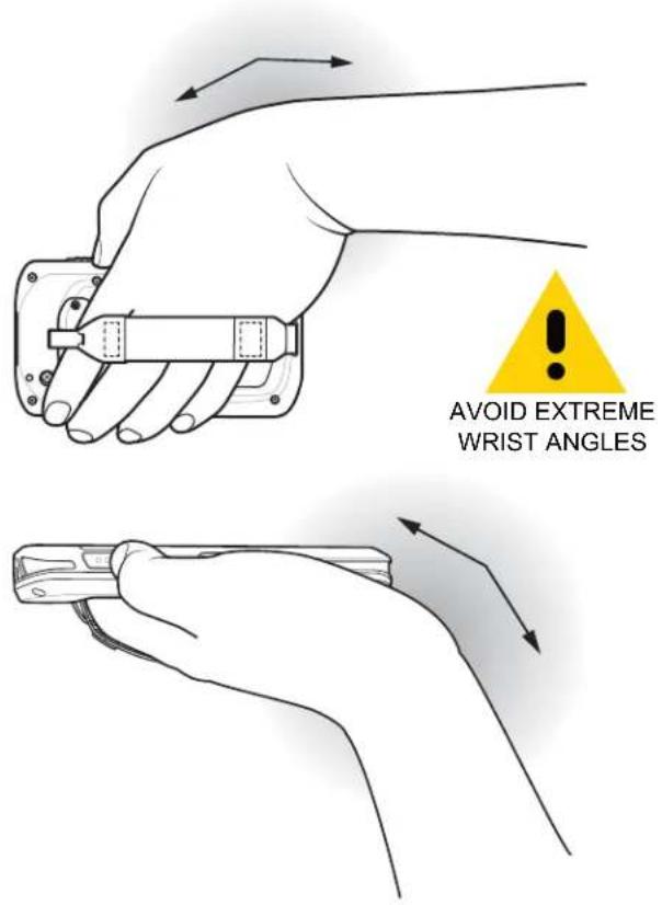
Ergonomic Recommendations
TC25 Touch Computer Quick Start Guide
Mærke : ZEBRA
Model : TC25
Kategori : Stregkodescanner