
SF-DX720 - Modtager TECHNICS - Gratis brugsanvisning og manual
Find enhedens vejledning gratis SF-DX720 TECHNICS i PDF-format.


Brugerspørgsmål om SF-DX720 TECHNICS
0 spørgsmål om dette apparat. Besvar dem du kender, eller stil dit eget.
Stil et nyt spørgsmål om dette apparat
Download vejledningen til din Modtager i PDF-format gratis! Find din vejledning SF-DX720 - TECHNICS og tag din elektroniske enhed tilbage i hånden. På denne side er alle dokumenter nødvendige for brugen af din enhed offentliggjort. SF-DX720 af mærket TECHNICS.
BRUGSANVISNING SF-DX720 TECHNICS
Digital Surround Processor AV Control Stereo Receiver
SF-DX7
Operating Instructions
natural_image
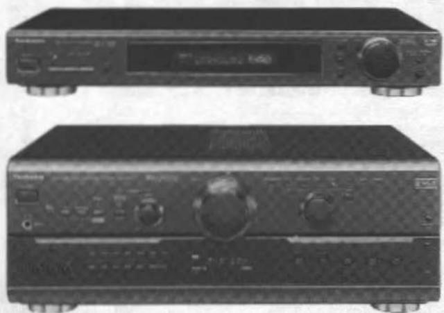
Two black electronic audio equipment units with control knobs and buttons, no visible text or symbols on the devices themselves.Remote control included.
Technics®
Before connecting, operating or adjusting this product, please read these instructions completely. Please keep this manual for future reference.
PP
RQT5110-P
Dear Customer
Thank you for purchasing this system.
For optimum performance and safety, please read these instructions carefully.
Front cover of the receiver is open in all explanations in these operating instructions.
The model number and serial number of this product can be found on either the back or the bottom of the unit.
Please note them in the space provided below and keep for future reference.
MODEL NUMBER SERIAL NUMBER
Processor: SH-AC500D
Receiver: SA-AX7
User memo:
DATE OF PURCHASE ____
DEALER NAME
DEALER ADDRESS
TELEPHONE NUMBER
Enjoying DVD and other digital sources
This system provides you with the opportunity to enjoy the high quality surround effects found on DVDs and other digital sources. Before you playback these sources, though, you need to prepare this system.
Follow these steps to get the most out of your system.
-
Connect the processor and receiver; page 8.
-
Connect the DVD player (or other digital equipment); page 9.
-
Connect your speakers; pages 14, 15, and 16.
-
Do the speaker settings on the processor; pages 28 to 31.
The system is now ready for playback.
Follow the steps on pages 32 and 33, and sit back and enjoy the powerful sounds on your system.
CAUTION
Do not place a tape deck, CD, or DVD player on top of the receiver.
Heat radiated from the top of this unit may cause damage to the software.

natural_image
Simple line drawing of a mechanical component with no text or symbolsNO
Table of contents
Precautions 4
Surround guide 5
Front panel controls 6
Equipment connections 8
Antenna connections 12
Speaker connections 14
Concerning the remote control 17
Basic operations....18
To enjoy bi-amp sound 20
To adjust the tone quality 20
To adjust the sound balance 20
To adjust the subwoofer level 21
To compensate when the volume is low 21
To adjust the output range of the subwoofer 21
Listening to radio broadcasts 22
Sequential tuning 22
Direct tuning 23
Preset tuning 24
Reproduction modes 26
On the processor 26
On the receiver 27
Preparation for DVD playback 28
Speaker settings for the processor 28
Adjusting speaker output level 29
Adjusting the delay time 31
Enjoying DVD 32
Preparing for Dolby Pro Logic on the receiver ..... 34
Setting the center mode and adjusting speaker output level .... 34
Adjusting the delay time 36
Enjoying sound modes on the receiver 37
Adjusting field of sound in the SFC mode 38
VGCA mode 39
Other functions 40
To mute the sound level 40
To listen through headphones 40
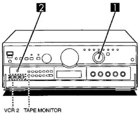
When using the VCR 2 terminals (front panel) 40
To turn off the blue light on the receiver
and dim the processor's display 41
Setting the midnight mode (dynamic range compression) ..... 41
Making a recording 42
Recording to a tape deck or VCR 42
Using the remote control 43
To operate the receiver 43
To operate the processor 45
To operate a cassette deck 46
To operate a CD changer or CD player 47
To watch TV broadcasts 48
To watch video tapes 49
To operate a DVD player 50
To watch satellite broadcasts 51
To watch cable TV 52
Changing the remote control code 53
About the HELP function 60
If the front cover comes off 60
Technical specifications 61
Troubleshooting guide....62
Listening caution .... Back cover
Maintenance Back cover
Product service Back cover
Supplied accessories

Please check and identify the supplied accessories.
☐ AC power supply cord (2 pc.)


(RJA0065-A)
□ AM loop antenna set
• AM loop antenna (1 pc.)
• AM loop antenna holder (1 pc.)
- Screw (1 pc.)
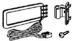
(RSA0010)
□ FM indoor antenna (1 pc.)
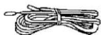
(RSA0006)
□ Stereo connection cable (2 pc.)


(RJL2P004B08)
□ Monaural connection cable (2 pc.)


(RJL1P011B15)
☐ Optical fiber cable (1 pc.)

(SJP2281)
□ Batteries (4 pcs.)

□ Remote control transmitter (1 pc.)
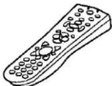
natural_image
Line drawing of a remote control with buttons and a circular head (no text or symbols)(RAK-SA954MK)
Use numbers indicated in parentheses when asking for replacement parts.
(Only for U.S.A.)
To order accessories contact 1-800-332-5368 or web site
(http://www.panasonic.com).
THE FOLLOWING APPLIES ONLY IN THE U.S.A.
CAUTION:
This equipment has been tested and found to comply with the limits for a Class B digital device, pursuant to Part 15 of the FCC Rules.
These limits are designed to provide reasonable protection against harmful interference in a residential installation. This equipment generates, uses and can radiate radio frequency energy and, if not installed and used in accordance with the instructions, may cause harmful interference to radio communications. However, there is no guarantee that interference will not occur in a particular installation. If this equipment does cause harmful interference to radio or television reception, which can be determined by turning the equipment off and on, the user is encouraged to try to correct the interference by one of the following measures:
- Reorient or relocate the receiving antenna.
- Increase the separation between the equipment and receiver.
- Connect the equipment into an outlet on a circuit different from that to which the receiver is connected.
- Consult the dealer or an experienced radio/TV technician for help.
Any unauthorized changes or modifications to this equipment would void the user's authority to operate this device.
This device complies with Part 15 of the FCC Rules. Operation is subject to the following two conditions: (1) This device may not cause harmful interference, and (2) this device must accept any interference received, including interference that may cause undesired operation.
WARNING:
TO REDUCE THE RISK OF FIRE, ELECTRIC SHOCK OR PRODUCT DAMAGE, DO NOT EXPOSE THIS APPLIANCE TO RAIN, SPLASHING, DRIPPING OR MOISTURE.
CAUTION:
TO PREVENT ELECTRIC SHOCK MATCH WIDE BLADE OF PLUG TO WIDE SLOT, FULLY INSERT.

CAUTION
RISK OF ELECTRIC SHOCK
DO NOT OPEN

CAUTION: TO REDUCE THE RISK OF ELECTRIC
SHOCK, DO NOT REMOVE SCREWS.
NO USER-SERVICEABLE PARTS
INSIDE.
REFER SERVICING TO QUALIFIED
SERVICE PERSONNEL.

The lightning flash with arrowhead symbol, within an equilateral triangle, is intended to alert the user to the presence of uninsulated "dangerous voltage" within the product's enclosure that may be of sufficient magnitude to constitute a risk of electric shock to persons.

The exclamation point within an equilateral triangle is intended to alert the user to the presence of important operating and maintenance (servicing) instructions in the literature accompanying the appliance.
Before using this unit please read these operating instructions carefully. Take special care to follow the warnings indicated on the unit itself as well as the safety suggestions listed below.
Afterwards keep them handy for future reference.
Safety
- Power Source—The unit should be connected to power supply only of the type described in the operating instructions or as marked on the unit.
- Polarization—If the unit is equipped with a polarized AC power plug (a plug having one blade wider than the other), that plug will fit into the AC outlet only one way. This is a safety feature. If you are unable to insert the plug fully into the outlet, try reversing the plug. If the plug should still fail to fit, contact your electrician to replace your obsolete outlet. Do not defeat the safety purpose of the polarized plug.
- Power Cord Protection—AC power supply cords should be routed so that they are not likely to be walked on or pinched by items placed upon or against them. Never take hold of the plug or cord if your hand is wet, and always grasp the plug body when connecting or disconnecting it.
- Nonuse Periods—When the unit is not used, turn the power off. When left unused for a long period of time, the unit should be unplugged from the household AC outlet.
Installation
Environment
- Outdoor Antenna Grounding—If an outside antenna is connected to the receiver, be sure the antenna system is grounded so as to provide some protection against voltage surges and built-up static charges. Section 810 of the National Electrical Code, ANSI/NFPA No. 70-1990, provides information with respect to proper grounding of the mast and supporting structure, grounding of the lead-in wire to an antenna discharge unit, size of grounding conductors, location of antenna-discharge unit, connection to grounding electrodes, and requirements for the grounding electrode. See figure below.

NEC—NATIONAL ELECTRICAL CODE
- Water and Moisture—Do not use this unit near water—for example, near a bathtub, washbowl, swimming pool, or the like. Damp basements should also be avoided.
- Heat—The unit should be situated away from heat sources such as radiators and the like.
It also should not be placed in temperatures less than 5°C (41°F) or greater than 35°C (95°F).
Placement
- Ventilation—The unit should be situated so that its location or position does not interfere with its proper ventilation. Allow 10 cm (4") clearance from the rear of the unit.
- Foreign Material—Care should be taken so that objects do not fall into and liquids are not spilled into the unit. Do not subject this unit to excessive smoke, dust, mechanical vibration, or shock.
- Magnetism—The unit should be situated away from equipment or devices that generate strong magnetic fields.
- Stacking—Do not place heavy objects, other than system components, on top of the unit.
- Surface—Place the unit on a flat, level surface.
- Carts and Stands—The unit should be used only with a cart or stand that is recommended by the manufacturer. The unit and cart combination should be moved with care. Quick stops, excessive force, and uneven surfaces may cause the unit and cart combination to overturn.
- Wall or Ceiling Mounting---The unit should not be mounted to a wall or ceiling, unless specified in this operating instructions.

Maintenance
Clean the cabinet, panel and controls with a soft cloth lightly moistened with mild detergent solution.
Do not use any type of abrasive pad, scouring powder or solvent such as alcohol or benzine.
Service
-
Damage Requiring Service—The unit should be serviced by qualified service personnel when:
(a) The AC power supply cord or the plug has been damaged; or
(b) Objects have fallen or liquid has been spilled into the unit; or
(c) The unit has been exposed to rain; or
(d) The unit does not appear to operate normally or exhibits a marked change in performance; or
(e) The unit has been dropped, or the enclosure damaged. -
Servicing—The user should not attempt to service the unit beyond that described in the operating instructions. All other servicing should be referred to an authorized service personnel.
For the address of an authorized servicenter:
In the U.S.A. 1-800-211-7262 or web site
(http://www.panasonic.com)
In Canada 905-624-5505 or web site
(www.panasonic.ca)
You are able to enjoy these surround systems with this system.
Surround system
Dolby Pro Logic
Features
Dolby Pro Logic is a decoding system that was developed to get a better sense of presence from sources encoded with Dolby Surround. The feeling of position has been improved by the addition of a separate center speaker channel. Dolby Surround was developed to allow enjoyment of Dolby Stereo, a cinema system, in private homes. This system reproduces sound close to that of the original movie through use of an analog matrix.
(→ Page 26, 27.)
Software
- Video tapes
- Laser discs
• DVDs
• CDs
Software encoded with Dolby Surround can be identified with this mark.

Dolby Digital (AC-3)
Dolby Digital is a discrete 6 (5.1) channel digital surround system developed for cinema use. The sound signals in Dolby Digital format are compressed to 1/12 their original size, allowing an entire movie to be recorded on a single DVD. Not all Dolby Digital sources are recorded with 6 channels. Some sources marked Dolby Digital may be recorded in Dolby Surround, a 2 channel system.
(→ Page 26.)
• DVDs
Software encoded with Dolby Digital can be identified with this mark.

DTS
DTS is a discrete 6 (5.1) channel digital surround system developed for cinema use. Sources encoded in DTS are only compressed to a quarter of the size of the original to preserve sound quality. DTS sources are produced with the intention that all speaker channels will be used.
(→ Page 26.)
• DVDs
- Laser discs
• CDs
Software encoded with DTS can be identified with this mark.

SFC (Sound Field Control)
The receiver itself produces the surround effects with sources other than those listed above. Various effects, like a concert hall or jazz club, can be achieved by introducing width or reverberation to the original sound.
(→ Page 27.)
Any kind, but particularly music CDs and video tapes.
Manufactured under license from Dolby Laboratories. "Dolby", "Pro Logic" and the double-D symbol are trademarks of Dolby Laboratories, Confidential Unpublished Works. © 1992-1997 Dolby Laboratories, Inc. All rights reserved.
Manufactured under license from Digital Theater Systems, Inc. US Pal. No. 5,451,942 and other world-wide patents issues and pending. "DTS" and "DTS Digital Surround" are trademarks of Digital Theater Systems, Inc. © 1996 Digital Theater Systems, Inc. All rights reserved.
Receiver (SA-AX7)

| No. | Name | Ref. page |
① Power “ ∅ / I ” switch (POWER, ∅ / I ) ...... 18
Press to switch the unit from on to standby mode or vice versa.
In standby mode, the unit is still consuming a small amount of power.
② Remote control signal sensor 17
③ Help/reset button (-HELP, -RESET)......60
④ Speaker select buttons (SPEAKERS A, B, BI-WIRE) 18
⑤ Bi-amp indicator (Bi-AMP) 20
⑥ Adaptive subwoofer control/indicator (SUBWOOFER ADAPTIVE CONTROL) ...... 21
⑦ Subwoofer level control (SUBWOOFER LEVEL) 21
⑧ Volume control (VOLUME)....18
⑨ Input indicators....18
⑩ VGCA mode select button/indicator (VGCA) 39
⑪ Input selector (INPUT SELECTOR) 18
⑫ Headphone jack (PHONES) 40
⑬ TV/DSS, VCR 2 input select button ( ■ TV/DSS, ■ VCR 2) .... 40
⑭ VCR 2 terminals (VCR 2)....10
⑮ Display
| No. | Name | Ref. page |
⑯ Bass control (BASS)....20
⑰ Treble control (TREBLE) 20
⑱ Balance control (BALANCE) 20
⑲ Bi-amp balance control (BI-AMP BALANCE) 20
⑳ Subwoofer low pass filter control (SUBWOOFER LOW PASS FILTER)....21
②1 Front cover open button (PUSH OPEN) ..... 19
② Tape monitor button (TAPE MONITOR) ..... 19
②3 DVD 6ch input select button (DVD 6CH INPUT)....29
②4 Dolby Pro Logic/SFC mode off button (STEREO) 37
② Dolby Pro Logic mode/center mode select button (-□□PRO LOGIC, -CENTER MODE) 27, 34
② Band select/FM mode select button (-BAND, -FM MODE) 22
⑰ Preset channel button (PRESET) 25
28 Memory button (MEMORY) 24
SFC mode select buttons (SFC HALL CLUB LIVE THEATER SIMULATED) 27
③ Tuning buttons (TUNING ∨, ∧) 22
Processor (SH-AC500D)
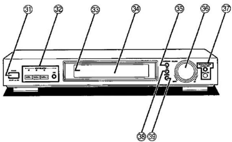
No.
Name
Ref. page
③1 Power button (POWER, ▲OFF - ON) ...... 28
③2 Input select buttons/indicators (DIGITAL 1, DIGITAL 2, DIGITAL 3, LINE)...... 32
33 Standby indicator
When the POWER button is in the ON position(=), the unit can be switched between the STANDBY and ON condition using the remote control and in this STANDBY condition the indicator will light.
③4 Display
③5 Surround mode button (SURROUND) ...... 26
③6 Volume control (VOLUME) 29
③7 Speaker setting button
(CHANNEL/SET, SELECTOR) 28
⑱ DTS mode button (DTS) 26
39 Stereo mode button (STEREO) 26
Speaker indicators and signal format indicators

Speaker indicators
Light in accordance with the speaker setting, and each of the indicators corresponding with the speaker concerned flashes when;
- the type or presence of that speaker is set,
- the test signal is output from that speaker,
- the output level or delay time of that speaker is adjusted.
Signal format indicators (LS, C, RS, L, R, S, LFE)
These indicators light up to indicate each input signal format.
LS: Surround speaker (left)
C: Center speaker
RS: Surround speaker (right)
L: Front speaker (left)
R: Front speaker (right)
"S" represents the mono surround and "LFE" (Low Frequency Effect) is a channel for the deep-bass effect in the low frequency range.
Make sure that the power supply for all components has been turned off before making any connections.
To connect equipment, refer to the appropriate operating instructions.
Note
Do not place books, etc., on the top of this unit or block the heat radiation vents in any way.
Connecting the receiver and processor

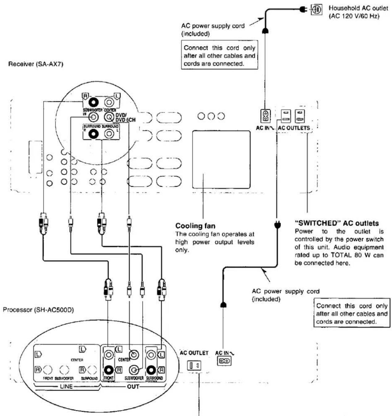
"UNSWITCHED" AC outlet
This is for the exclusive use of an audio component. It can be used to supply power to a component regardless of whether the unit's POWER button is at the ON or OFF position. Use it for any unit having a rating of 50 W or less.
Connecting a DVD player and other digital equipment

DVD player (not included)
Other digital playback sources (laser disc players, etc.) (not included)
Optical fiber cable connections A
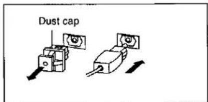
- Do not bend the optical fiber cable.
- Attach the dust caps when the optical terminals are not in use.
"DIGITAL 1" terminals B
Disconnect the coaxial cable from the DIGITAL 1 terminal when using an optical fiber cable. Only the coaxial cable is recognized if both types are connected.
"LINE IN" terminals ©
If "LINE" is selected with the input selector on this processor, the signals received through these terminals are output as they are without passing through any sound control circuits (i.e. no volume or other sound adjustments can be made with this processor.)
Note
- Dolby Digital RF (radio frequency) signals cannot be decoded with this processor even if a unit that has Dolby Digital RF output terminals is connected to this processor.
- Turn off the power to this processor if unusual hissing or beat sounds are heard while listening to FM, AM, or television broadcasts.
Connecting audio and video equipment
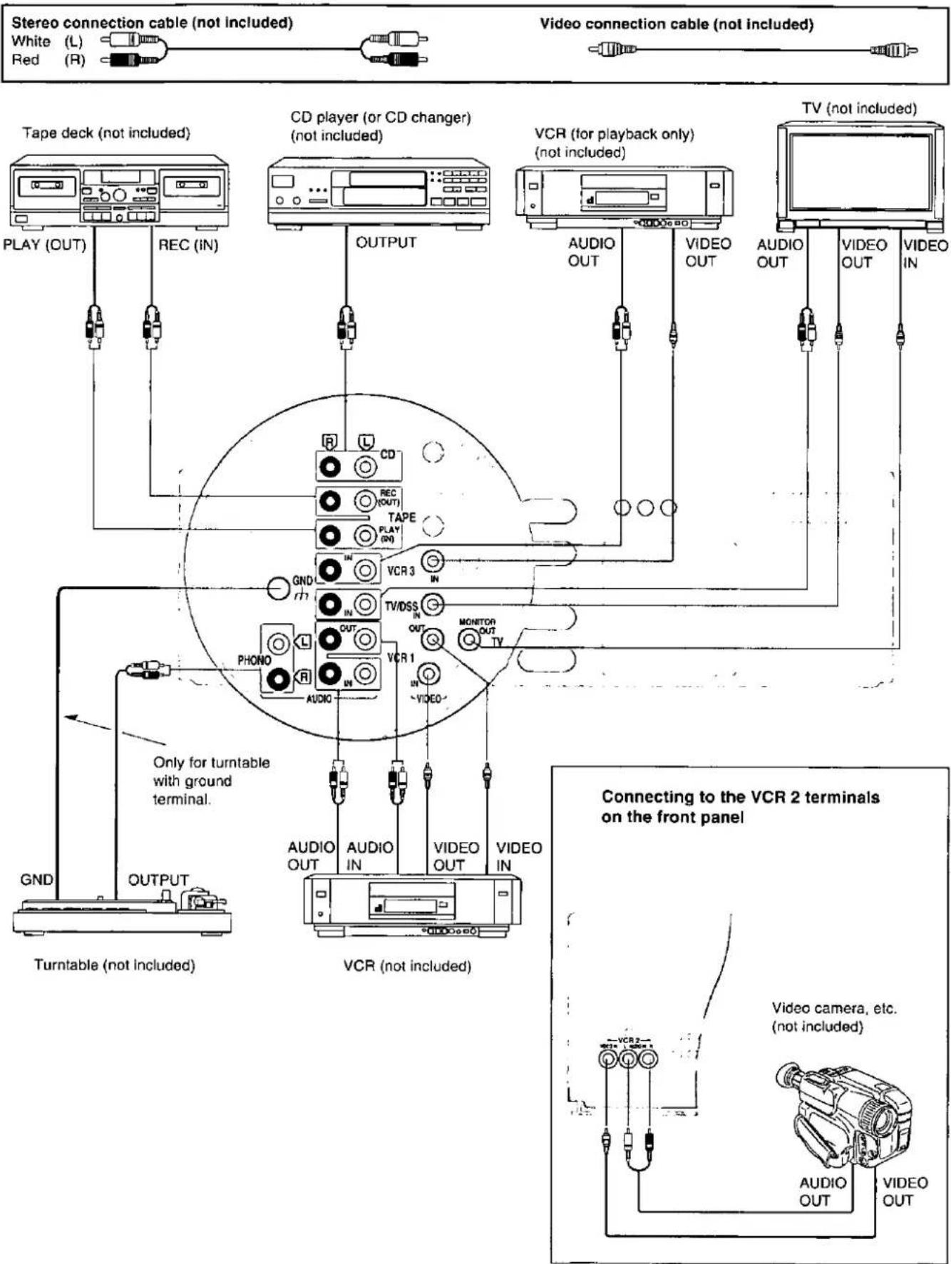
Connections to/from S-VIDEO
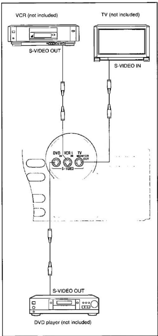
flowchart
graph TD
    A["VCR (not included)"] -->|S-VIDEO OUT| B["TV (not included)"]
    C["S-VIDEO IN"] -->|S-VIDEO OUT| D["DVD player (not included)"]
    B --> E["TV MONITOR OUT"]
    D --> F["DV R1 IN"]
    style A fill:#f9f,stroke:#333
    style C fill:#f9f,stroke:#333
    style B fill:#ccf,stroke:#333
    style D fill:#ccf,stroke:#333

This receiver has an S-VIDEO terminal for a DVD player, VCR (VCR 1 only) and TV.
Caution when using a TV with an S-VIDEO terminal
On some television models, the video signal from components which do not use S-VIDEO input and are connected only to the VIDEO terminals will not be shown on the television screen. If this occurs, use one of the following methods to view the video signal.

flowchart
graph TD
    A["Does the television have a "VIDEO/S-VIDEO" selector switch?"] --> B{YES}
    A --> C{NO}
    B --> D["Set the switch to "VIDEO"."]
    B --> E{If the television has two or more video input terminals}
    E --> F["Connect the VIDEO terminal and the S-VIDEO terminal to different video input terminals on the television, and switch the picture on the television according to the video source being played."]
    E --> G{If the television has only one video input terminal}
    G --> H["Disconnect the S-VIDEO cable connected to the television's S-VIDEO terminal and connect only the video terminal."]
Note
When using S-VIDEO terminals be aware of the following. Video signals input into the VIDEO terminals cannot be output from S-VIDEO terminals or vice versa.
A
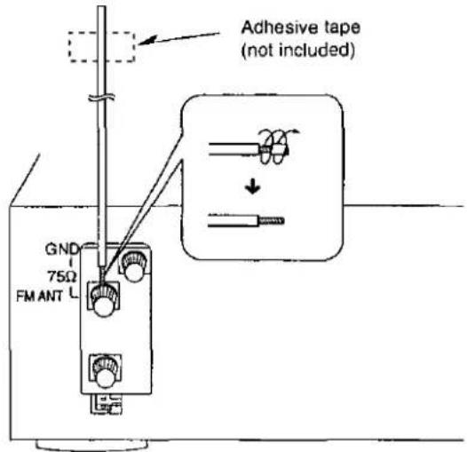
FM indoor antenna (included)
B
C
Antenna connections
FM indoor antenna (included)
A
This antenna is normally sufficient for reception of FM broadcasts.
Attach to a wall (using tape) facing in the direction of best reception.
For best reception
An FM outdoor antenna is recommended.
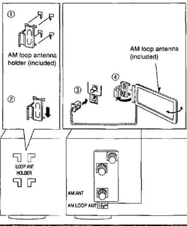
AM loop antenna (included)
B
This antenna is normally sufficient for reception of AM broadcasts.
Fit the AM loop antenna holder (included) onto the rear panel of this unit and then attach the AM loop antenna to the AM loop antenna holder (facing in the direction of best reception).
Pay attention to the following points when mounting the antenna.
- Do not mount it close to power cords, speaker wires or metal surfaces (doing so will result in noise).
- Do not mount it close to a tape deck. When the tape deck is being used, chirping or beeping sounds may result.
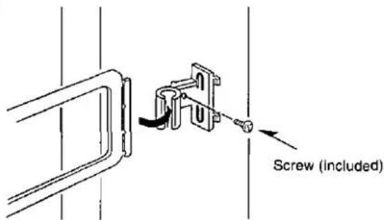
When mounting the antenna to a column, a wall or rack C
Mount the antenna so that the hinge is vertical.
A

B

FM outdoor antenna (not included)
A
An outdoor antenna should be used when using this unit in mountainous areas or in spaces enclosed by reinforced concrete where the FM indoor antenna (included) does not provide satisfactory reception.
Disconnect the FM indoor antenna if an FM outdoor antenna is installed.
Note
An outdoor antenna should be installed by a qualified technician only.
AM outdoor antenna (not included)
B
An outdoor antenna should be used when using this unit in mountainous areas or in spaces enclosed by reinforced concrete where the AM loop antenna (included) does not provide satisfactory reception.
Stretch 5–12 m (16–40 ft.) of vinyl-covered wire horizontally across a window frame or other convenient location, keeping it as high as possible from the ground.
When the unit is not in use, disconnect the outdoor antenna to prevent possible damage that may be caused by lightning. Never use an outdoor antenna during an electrical storm.
Note
Be sure to connect the AM loop antenna even when an outdoor antenna is used.
Placement of speakers
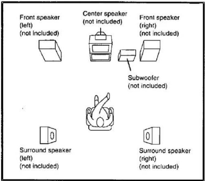
Front speakers
Place the front speakers on the left and right of the TV at seated ear height so that there is good coherency between the picture and sound.
Center speaker
Place this speaker underneath or above the center of the TV. Aim the speaker at the seating area.
Surround speakers
Place these speakers on the side of or slightly behind the listener, and about one meter higher than ear level.
Subwoofer
The subwoofer can be placed in any position as long as it is at a reasonable distance from the TV.
Note that some experimentation can yield the smoothest low frequency performance. Placement near a corner can increase the apparent output level, but can result in unnatural bass.
Connecting speakers
Other connections are possible depending on your speaker system. See your speaker system's operating instructions for details.
Front speakers

Note
Use the A terminals to enjoy Dolby Pro Logic, SFC, and DVD 6CH INPUT.
Bi-wiring connection
Note
When bi-wiring, use speakers designed for that purpose that have combined impedance of 6–8 Ω
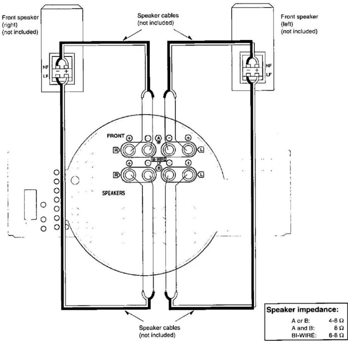
Connecting the cables


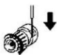
NO

Note
To prevent damage to circuitry, never short-circuit positive (+) and negative (−) speaker wires.
If using a commercially available 4 mm plug cord
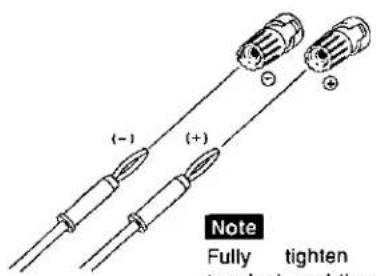
Note
Fully tighten the speaker terminal, and then insert the end of the plug cable into the top of the terminal.
Other speakers

Speaker impedance:
| Center speaker: | 6-8 Ω |
| Surround speaker: | 6-8 Ω |
| Subwoofer: | 6-8 Ω |
A

B
Remote control signal sensor

Concerning the remote control
Battery installation
A
Use of batteries
- Do not mix old and new batteries, or batteries of different types (manganese and alkaline, etc.).
- Never subject batteries to excessive heat or flame; do not attempt to disassemble them; and be sure they are not short-circuited.
- If the remote control is not to be used for a long period of time, remove the batteries and store them in a cool, dark place.
- Do not attempt to recharge alkaline or manganese batteries.
- Do not use rechargeable type batteries.
- Use alkaline batteries for longer life.
Correct method of use
B
Operation notes
- Do not place obstacles between the remote control signal sensor and remote control unit.
- Do not expose the remote control signal sensor to direct sunlight or to the bright light of an inverter fluorescent light.
- Take care to keep the remote control signal sensor and end of the remote control unit free from dust.
- If the unit is installed in a rack with glass doors, the glass doors' thickness or color might make it necessary to use the remote control a shorter distance from the unit.
To prevent damage
- Never place heavy items on top of the unit.
- Do not disassemble or reconstruct the unit.
- Do not spill water or other liquids into the unit.



Basic operations
Before operation, set [VOLUME] to the "MIN" position.
1 Press [POWER].
2 Select the speaker system(s) to be used.
The buttons A, B and BI-WIRE refer to the speaker terminals at the rear of the unit.
If the button is pressed once more, the indicator will switch off and no sound will be heard from the speakers.
BI-WIRE and A, or BI-WIRE and B cannot be used at the same time.
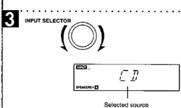
3 Turn [INPUT SELECTOR] to select and start the desired source.
(Refer to the appropriate operating instructions for details.)
The indicator corresponding to the selected source lights and the source is shown on the display.
The selected source and "INPUT" will be shown on the display.
TAPE (MONITOR): To listen to cassette tapes
VCR 1: To watch video tapes (VCR 1)
TV/DSS/VCR 2: To watch TV, DSS or video tapes (VCR 2)
VCR 3: To watch video tapes (VCR 3)
DVD: To use the digital surround processor
CD: To listen to compact discs
TUNER: To listen to radio broadcasts
PHONO: To listen to phono discs
Note
To watch a video (or DVD) or the TV, set the TV to either the TV mode or VIDEO mode.
4 Adjust the volume level.
For your reference
- If a Dolby Pro Logic or SFC mode has been selected
After displaying the selected source, the display will then change to show the Dolby Pro Logic or SFC mode and "INPUT" will go out (→ page 27).
If the source chosen was TUNER then the display will change again to show the frequency.
- If you are using VCR and you select TAPE, CD, TUNER, or PHONO
The picture will remain on the screen.
• The volume control
The volume control on this receiver allows more gradual adjustment compared to past models, thus making it easier to make fine volume adjustments during normal use.
When you finish listening
Be sure to reduce the volume level, and switch the power to the standby condition by pressing [POWER].

A

B


C

Basic operations
To open the front cover A
Press [PUSH OPEN].
Push the cover closed by hand.
For front speakers with an impedance under 6 Ω B
Press and hold [A] or [B] until "LOW IMP" lights up on the display.
If even one of the speakers being used has an impedance under 6 Ω, press and hold down either [A] or [B] for 4 seconds or more to set the impedance on the main unit to LOW.
(Press and hold down once again for 4 seconds or more to turn it off.)
Note that when "LOW IMP" is illuminated, speakers A and B cannot both be used at the same time.
To change speakers when "LOW IMP" is on:
e.g. To use speakers B, press [A] ("A" goes out), and then press [B] to activate speakers B.
The TAPE (MONITOR) indicator
This indicator lights in the following two situations:
- While TAPE is selected.
- While TAPE MONITOR is in use.
Tape monitor ©
If [TAPE MONITOR] is pressed while a source other than TAPE is selected, the "TAPE (MONITOR)" indicator lights and the tape monitor comes on.
Sources other than tape can still be selected with [INPUT SELECTOR] while the "TAPE (MONITOR)" indicator is on.
Press [TAPE MONITOR] again to turn the tape monitor off.
(→ See "Making a recording" on page 42 for details on how to use the tape monitor during recording.)
A

B

C

D

Basic operations
To enjoy bi-amp sound
A
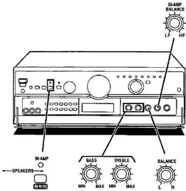
By using the bi-wiring feature of this unit to connect your speakers, you are able to take advantage of two separate amplifiers for the high frequency and low frequency ranges. This enables more highly defined sound reproduction of the two ranges thus producing high quality bi-amp stereo sound.
Ensure "BI-AMP" illuminates when BI-WIRE is selected.
BI-AMP will turn off and the indicator will go out in the following cases:
- If any of the Dolby Pro Logic or SFC modes are turned on.
- If DVD 6CH INPUT is selected.
To adjust the high and low balance B
Turn [BI-AMP BALANCE] to adjust the LF/HF balance
This adjusts the high and low frequency output of bi-wired front speakers.
The setting depends on the speakers being used. Adjust the balance to suit your room's acoustics and the features of the speakers.
To adjust the tone quality
C
Turn [BASS] to adjust the low frequency sound. Turn [TREBLE] to adjust the high frequency sound.
To adjust the sound balance
D
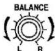
Turn [BALANCE] to adjust the left/right sound balance.
Basic operations
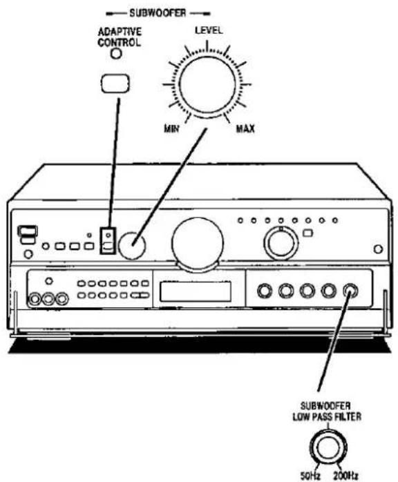
To adjust the subwoofer level
A
Turn [SUBWOOFER LEVEL] to adjust its level.
If the subwoofer isn't being used, be sure to set it to MIN.
To compensate when the volume is low
B
This button balances low volume sounds by boosting bass sound pressure of the front speakers and subwoofer.
This function allows you to enjoy balanced sounds even if the volume is low.
Press [SUBWOOFER ADAPTIVE CONTROL].
The message "ON" will appear on the display for 2 seconds. "SUBWOOFER ADAPTIVE CONTROL" will light up.
To return to the previous condition, press once again.
The message "OFF" will appear on the display for 2 seconds, then the indicator turns off.
To adjust the output range of the subwoofer
C
Turn [SUBWOOFER LOW PASS FILTER] to select a suitable frequency.
The setting depends on the room's acoustics, the peculiarities of the subwoofer, and the interaction of the subwoofer and the front speakers.
Note
Adjustments can not be made when DVD 6CH INPUT has been selected.


1
INPUT SELECTOR


2


3

Listening to radio broadcasts
Sequential tuning
Use the tuning buttons to tune-in radio stations.
1 Turn [INPUT SELECTOR] to select "TUNER."
2 Press [-BAND, -FM MODE] to select "FM" or "AM."
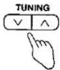
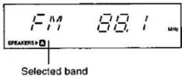
3 Press [TUNING (∨ or ∧)] to tune to the desired frequency.
"TUNED" lights up when tuned.
"STEREO" lights up when an FM stereo broadcast is received.
To make an automatic search for stations
If [TUNING (V or A)] is held down for an instant until the frequency begins to scroll, the broadcast stations are tuned in automatically when one is found.
Note
Tuning may stop automatically if any jamming is encountered.
If noise is excessive in the FM stereo mode
Press and hold [-BAND, -FM MODE] for 2 seconds.
("STEREO" will go out, and "MONO" will light up).
The broadcast will be monaural, but noise will be reduced.
If the button is pressed and held for 2 seconds once more, the stereo mode resumes.
For your reference
The tuner can pick up interference from DVD players. If this occurs turn the DVD player off.
1

2
3


4

Listening to radio broadcasts
Direct tuning
by remote control only
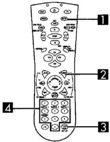
Specify the frequency using the numeric buttons on the remote control transmitter to directly tune to the desired station.
1
Press [RCVR] to switch to the receiver operation mode.
The button lights up.
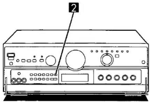
2
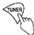
Press [TUNER].
The selector on the receiver will change to "TUNER." Each time the button is pressed, the band will change as follows, FM ← AM.
3
Press [TUNE ENT].
4
While cursor display is flashing (approx. 10 seconds) Press the numbered buttons to enter the frequency.
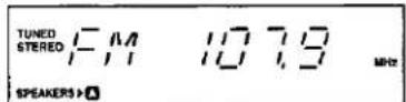
If the desired FM frequency is 107.9 MHz, press 1079 .
If the frequency has been input correctly, the displayed frequency will blink once.
Note
- If no button is pressed while the cursor display is flashing, the display will return to the frequency which is currently being received.
To re-specify the frequency, repeat the procedure from step 3. - If the frequency has not been input correctly, "ERROR" will be displayed.
In this case, re-enter the frequency.
2


A

Preset tuning
Presetting radio stations into the memory channels of this unit makes selecting stations simple.
A total of 30 FM and AM stations can be preset.
Please remember this
If a new broadcast station is preset into a channel, the setting for the broadcast station which was previously entered in that channel will be automatically erased.
Automatic memory presetting
Automatic memory presetting allows this unit to automatically search for broadcast stations and then preset them into memory. With this method, the channels that can be preset into the memory are set as follows for different bands (FM or AM).
When FM stations are preset,
For FM stations....1-30
When FM and AM stations are preset,
For FM stations.... 1-20
For AM stations 21-30

Set to the frequency from which you want to start automatic memory presetting.
(→ Page 22-23.)

Press [MEMORY] until the frequency begins to change.
(Automatic memory presetting will start.)
During automatic memory presetting, the memory indicator will flash while the frequency scrolls.
To stop, press [MEMORY] again.
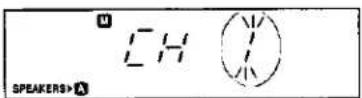
When a broadcast station is preset A
The memory indicator and the preset channel number will be displayed for approximately 1 second.
When presetting is completed
The last broadcast station to be preset will be displayed.
Note
Frequencies may not be preset correctly in cases where the broadcast waves are too strong or too weak. In such cases, carry out presetting manually. ( Page 25.)
A

2
MEMORY


3
TUNING

4


B
1
2


Listening to radio broadcasts
Manual memory presetting A
Stations can be preset into the desired channels by the user.

Set to the desired frequency.
(→ Page 22-23.)
If interference or static is keeping you from enjoying an FM broadcast, press and hold [-BAND, -FM MODE] and change to monaural.
You can preset the station in monaural just as in stereo.

Press [MEMORY].
To cancel the memory function, press [MEMORY] again.
![TECHNICS SF-DX720 - Press [MEMORY]. - 1](/content/2026/05/862583/images/9dfad2a167063867d9b2958b98401892b99cbf1f80b896db719ada3ef9717ed9.jpg)
Press [TUNING (∨ or ∧)] to select the desired channel.
Holding the buttons down lets you scroll through channels faster.
![TECHNICS SF-DX720 - Press [TUNING (∨ or ∧)] to select the desired channel. - 1](/content/2026/05/862583/images/b329176387049f538c64ce8bff1746825a1bdc0639ee37c880d2931e01d549bf.jpg)
Press [MEMORY].
The channel will blink on the display.
To continue presetting
Repeat steps 1 through 4.
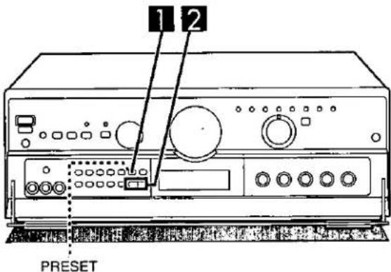
To listen to preset channels B

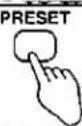
Press [PRESET].
![TECHNICS SF-DX720 - Press [PRESET]. - 1](/content/2026/05/862583/images/8b75072636d7fe541c58f493665f91bf283303771bcd599163bdc7382c310a48.jpg)
Press [TUNING (∨ or ∧)].
Holding down the buttons lets you scroll through channels faster.
The channel number flashes for approximately 5 seconds. Select the desired channel number during that time. After 5 seconds, the display will change from the channel number to the frequency.
Note
If you press [PRESET] while the channel number is displayed, the display will change to the frequency.
To confirm the channel number of the broadcast station being received
Press [PRESET].
(The channel number flashes for approximately 5 seconds.)
Note
The channel number is not displayed if you change the frequency or FM mode setting.
For your reference
Even if the power cord is disconnected from the household AC outlet, the memory will retain its contents for approximately one month.
If frequency presettings are accidentally erased
Program the presettings once again.
The power cord should remain connected for one hour or more for the memory back-up to be effective.
A
SURROUND


B

C
STEREO


Reproduction modes
On the processor
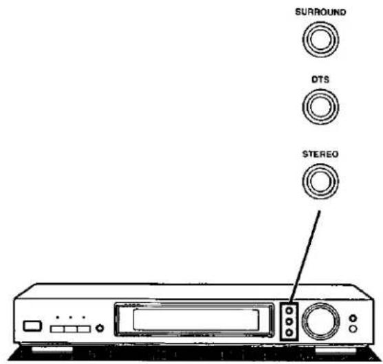
Use these modes to enjoy DVDs and other digital sources that have been connected to the processor through the digital optical terminals. The receiver should be in the DVD 6CH INPUT mode.
SURROUND mode A
Select this mode when playing back sources (DVD, CD, laser disc, etc.) recorded in either Dolby Digital or Dolby Surround Format. The unit processes most types automatically.
Normal audio CDs can also be played back. The unit processes the 2 channel signal into surround signals and sound is heard from all the speakers.
As well as normal audio CDs, software with any of the following marks can be played back in this mode.



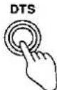
DTS mode B
Select this mode when playing back sources (DVD, CD, laser disc, etc.) recorded in DTS format.
Software with the following mark can be played back in this mode.

STEREO mode ©
Select this mode to listen to surround sources, other than DTS, in stereo. The down-mix function of this unit concentrates the discrete signals into the front L/R channels. Use this mode when using headphones or recording onto a video cassette recorder. Select this mode to listen to normal stereo software.

Reproduction modes
On the receiver
Use these modes to enjoy any source (video tapes, CDs, etc.) other than DVD 6CH INPUT.
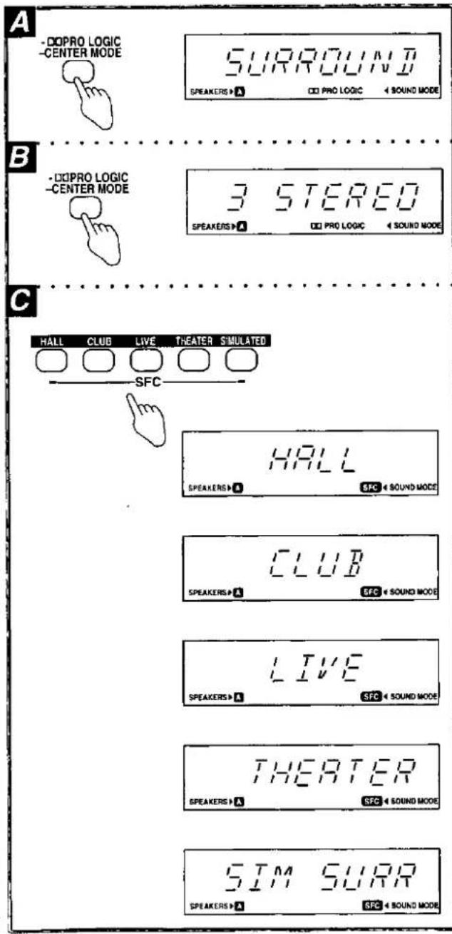
Dolby Pro Logic SURROUND mode A
By reproducing the feeling of depth and movement of sound, video software or compact discs recorded with Dolby Surround provide the listener with a feeling of presence like that of a movie theater.
Dolby Pro Logic 3 STEREO mode B
You can enjoy audio/video sources with clear sound, more presence and a good feeling of orientation. 3 STEREO can be used with stereo sources not encoded with Dolby Surround.
SFC mode ©
The SFC (Sound Field Control) function gives presence and spread thereby enhancing and enriching the music or movie. Read the following explanations to better understand how to make your selection.
Note
- SFC is designed to add surround-like effects to stereo sources. Select the Dolby Pro Logic SURROUND mode when playing back Dolby Surround sources.
- The center speaker is not used in the HALL and SIMULATED mode
HALL
This mode imparts a reflection and spread which will make you feel as if you are in a large concert hall.
CLUB
Like a jazz club, this mode provides an exciting and intimate atmosphere. It simulates the sound field of a relatively small room having a low ceiling and hard reflective surfaces, for a "live" sound with enhanced presence to bring the performers up close.
LIVE
Primarily for vocal pieces, this mode adds gloss to the vocals and you'll feel as though you were hearing a live stage performance.
THEATER
You can clearly perceive the directions and source of the movie. Real ambience of sound can also be recreated naturally using this mode.
SIMULATED (SIM SURR)
Choose this mode if little or no sound will be heard from the surround speakers.
You can feel as if you were in a more expanded space adding to the actual sound from the source.
This mode also adds effect to monaural sources by outputting sound from surround speakers.

1

2
CHANNEL/SET

flowchart
graph TD
    A["FRONT"] --> B["CENTER"]
    B --> C["SURROUND"]
    C --> D["SUB-WFA"]
    D --> E["COMPLETE"]
3
SELECTOR





Preparation for DVD playback
Speaker settings for the processor
Set the type and presence of the speakers before playing the sound by reproducing the input source.
Before proceeding
Check the frequency range of each speaker to be used. Consider speakers capable of playing back low frequency sounds (below around 100 Hz) as LARGE. Consider speakers not capable of playing back low frequency sounds as SMALL.

Press [POWER].
![TECHNICS SF-DX720 - Press [POWER]. - 1](/content/2026/05/862583/images/311db8558e585061bb110ed8311130575e2ff81501a8826297214ceb0eece311.jpg)
Press [CHANNEL/SET], and select the speaker channel to be set.
Each time the button is pressed, the channel display is switched in the listed order.
FRONT: Front speakers
CENTER: Center speaker
SURROUND: Surround speakers
SUB-WFR: Subwoofer
COMPLETE: Select this when you have completed the settings.
The selected channel is shown on the display for approx. 2 seconds. The current setting for that channel is then shown as a flashing display. The indicator corresponding to the selected speaker also continues to flash.
![TECHNICS SF-DX720 - Press [CHANNEL/SET], and select the speaker channel to be set. - 1](/content/2026/05/862583/images/c3fa63c8ede82028b8e3c4da6ac156de656e5ef752cf605e7946f82ac9d427b3.jpg)
Press [SELECTOR], and set the type (LARGE, SMALL) and presence (YES, NO or NONE) of the speaker.
Each time the button is pressed, the display is switched in the listed order.
LARGE: select if the speaker can produce low frequency sounds,
SMALL: select if the speaker cannot produce low frequency sounds,
NONE: select if you are not using a center speaker or surround speakers,
YES: select if you are using a subwoofer,
NO: select if you are not using a subwoofer.
The sound for speaker channels that are set to "NONE" or "NO" are output from the front speakers.
![TECHNICS SF-DX720 - Press [SELECTOR], and set the type (LARGE, SMALL) and presence (YES, NO or NONE) of the speaker. - 1](/content/2026/05/862583/images/61a39f60e0504cba9858cbbfb95ff1dd0fd7378bfa1248e691a82761c164f74d.jpg)
Repeat steps 2 and 3 to complete the settings for all the channels.

Press [CHANNEL/SET] to select "COMPLETE."
The settings are now entered into the unit's memory. The display goes out after about 2 seconds and the previous display reappears.
The speaker indicators light up unless "NONE" or "NO" has been selected for the corresponding channel.
If no buttons are pressed for approx. 10 seconds during the setting process, all previous settings are cancelled, the setting mode is released, and the original display is restored.
Begin the setting process again if this occurs.
For your reference
The setting remains as it is until changed by the above procedure, even after the power has been turned off.
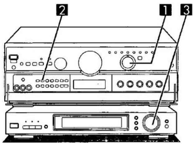

Adjusting speaker output level
Adjust speaker level so the output from all the speakers is the same apparent level when sitting where you would normally enjoy a source.
Preparation for the receiver
- Turn ON the speakers with [A] or [BI-WIRE].
- Adjust front speaker balance with [BALANCE].
1 Turn [INPUT SELECTOR] to select "DVD" on the receiver.
2 Press [DVD 6CH INPUT] to select "DVD-6CH." Changes as follows, each time the button is pressed. DVD 6CH ⇌ DVD (2CH)
If you press this button while another source (CD, PHONO, etc.) is selected, the receiver switches the source to DVD and engages the DVD 6CH INPUT mode.
3 Set the volume level to 0 dB on the processor.
4 by remote control only
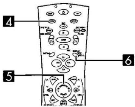
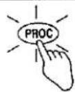
Press [PROC] to switch to the processor operation mode.
The button lights up.
5 by remote control
Press [SURROUND] to select the surround mode.
"SURROUND" appears on the display.
6 by remote control only
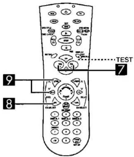
Press [TEST] to output the test signal.
"TEST" appears on the display, and the speaker indicator corresponding to the speaker outputting sound flashes.
The test signal is automatically output from each speaker for 2 seconds in the following sequence:
L → C → R → RS → LS → SW
L: Front speaker (left)
C: Center speaker
R: Front speaker (right)
RS: Surround speaker (right)
LS: Surround speaker (left)
SW: Subwoofer
(Speakers for which NONE or NO has been set are skipped.)
(Continued on next page)
7

8

flowchart
graph TD
    A["1"] --> B["2"]
    B --> C["3"]
    C --> D["4"]
9


Preparation for DVD playback

by remote control
Press [VOL -] or [VOL +] to set the receiver's volume level normally used for enjoying the source.

by remote control only
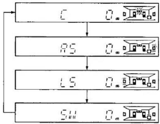
Press [LEVEL CH SELECT] to select the speaker channel to adjust.
The output level appears on the display, and the speaker indicator for the selected speaker flashes.
Each time the button is subsequently pressed, the speaker whose level is to be set is selected in the listed sequence. (Speakers for which NONE or NO has been set are skipped.)

by remote control only
Press [LEVEL ∨] or [LEVEL ∧] to adjust the output level.
Channels C, RS, LS, and SW can be adjusted between -12 dB and +12 dB. Set them so that the output from each channel appears to be the same as that from the front speakers.

Repeat steps 8 and 9 to adjust the output of each channel to approximately the same apparent level.
To stop the test signal
Press [TEST].

1
2


3


4

A
Front speaker (left)
flowchart
graph TD
    A["Center speaker"] -->|D1| B["Sound speaker"]
    C["Front speaker (right)"] -->|D3| B
    D["Surround speaker (right)"] -->|D2| B
    B --> E["Central device with hand gesture"]
Preparation for DVD playback
Adjusting the delay time
by remote control only
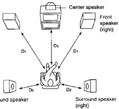
By adjusting the delay time, the difference in the distance from the viewing and listening position to the front speakers and the distance to the center speaker and surround speakers can be offset and made equal. This achieves better sound localization and makes a more life-like reproduction of the sound field possible.
Note
Please note that the following occurs if delay time is adjusted while playing back a source or analog input is selected:
- Adjustment is not possible if the source is DTS format.
- While the DOPRO LOGIC indicator is alight, the center channel cannot be adjusted and 15 ms are added to the delay times listed for the surround channel.
1
Press [PROC] to switch to the processor operation mode.
The button lights up.
2
Press [SURROUND] to select "SURROUND."
"SURROUND" appears on the display.
3
Press [DELAY CH SELECT] to select the channel to be adjusted.
The current delay time is displayed.
The speaker indicator for selected speaker flashes.
Press again to change the speaker channel;
C (Center speaker) ⇌ S (Surround speakers)
Speakers set as "NONE" are skipped.
4
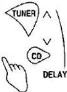
Press [DELAY ∨] or [DELAY ∧] to set the delay time.
The delay time changes with each press.
The increments depend on the channel being adjusted.
| Speaker | Available delay time setting (ms) |
| Center | 0, 1, 2, 3, 4, 5 |
| Surround | 0, 5, 10, 15 |
The display is restored if a button isn't pressed for 4 or more seconds.
To calculate the delay time A
D1: Distance from front speakers
D2: Distance from surround speakers
D3: Distance from center speaker
Setting the center channel delay time:
| If D1 is equal to or less than D3 | Set to 0 ms |
| If D3 is less than D1 | Increase 1 ms for every 30 cm of difference between D1 and D3 |
Setting the surround channel delay time:
| If D1 is equal to or less than D2 | Set to 0 ms |
| If D2 is less than D1 | Start at 0 ms and increase by 5 ms for every 1.5 m of difference between D1 and D2 |

1
INPUT SELECTOR
2


3

Enjoying DVD
Dolby Digital, DTS and other 6 channel discrete sources are recorded with each speaker channel discrete from the other.
Depth, movement, position and other characteristics are maintained, so using this mode will make you feel as if you were at a movie theater.
Ensure you have your speakers set up in either of the following ways.
- The front speakers are connected to the A terminals (→ page 14) and "SPEAKERS A" is selected.
- The front speakers are bi-wired (→ page 15) and "SPEAKERS BI-WIRE" is selected.

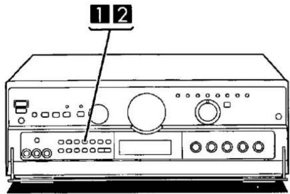
Turn [INPUT SELECTOR] to select "DVD" on the receiver.

Press [DVD 6CH INPUT] to select "DVD 6CH" on the receiver.
Note
- This mode cannot be turned on while SPEAKERS B is on. This mode is automatically cancelled if SPEAKERS B is selected and the modes in the memory for all sources will also be switched to STEREO. The modes must be selected again for all sources when SPEAKERS B is turned off again.
- BI-AMP and DVD 6CH INPUT cannot be used at the same time. If you are using BI-AMP and you select DVD 6CH INPUT, BI-AMP will turn OFF and the "BI-AMP" indicator will go out.

Press one of the processor's input select buttons to select the input source.
The indicator above the pressed button now lights.
DIGITAL 1: Selects the source connected to the DIGITAL 1 terminal. The unit automatically recognizes whether the source is connected through the optical fiber cable or the coaxial cable.
Note
If both types are connected at the same time, only the coaxial cable is recognized. Disconnect the coaxial cable if the external unit is connected with the optical fiber cable.
DIGITAL 2: Selects the source connected to this terminal.
DIGITAL 3: Selects the source connected to this terminal.
LINE: Selects the source connected to the LINE terminal.
When DIGITAL 1, 2 or 3 has been selected:
The reproduction modes in step 4 can be selected.
When LINE has been selected:
The analog sound signals input through LINE IN terminals are directly output to the connected component. "THROUGH" appears on the display.
Note
Only the POWER button and select buttons function when LINE has been selected.
(Continued on next page)

natural_image
Front view of a portable electronic device with ports and a labeled indicator (no text or symbols beyond the number 4)4
SURROUND


DTS


STEREO


5
a

b

©

Enjoying DVD

Press [SURROUND], [DTS] or [STEREO] to select the reproduction mode.
The selected reproduction mode appears on the display (→ page 26 for descriptions of the modes.)
![TECHNICS SF-DX720 - Press [SURROUND], [DTS] or [STEREO] to select the reproduction mode. - 1](/content/2026/05/862583/images/7ffa310be204aa567a83ebada686f22f932d67bf902005d715d1cee48ba8fb98.jpg)
Start the desired source.
Follow your equipment's operating instructions.
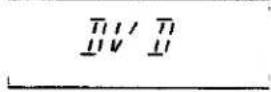
The surround indicators
④ DIGITAL: Lights if the source is Dolby Digital Format.
(b) lights: Lights if the source is DTS format.
© PRO LOGIC: Lights when Dolby Surround parts of Dolby Digital format software are played back, or when playing audio CDs in the SURROUND mode.
Only Dolby Digital, DTS or PCM signals * can be reproduced through the digital terminal:
- The digital input signal of sampling frequencies 96 kHz and other signal formats such as MPEG cannot be reproduced on this unit.
- When playback is started, the sound may be cut or interrupted before the input source is confirmed as Dolby Digital or DTS.
※ PCM signal: This refers to the recording format of signals (44.1 kHz, linear 16 bits) used for audio CDs.

Preparing for Dolby Pro Logic on the receiver
Setting the center mode and adjusting speaker output level
Adjust speaker level so the output from the center and surround speakers is the same apparent level when sitting where you would normally enjoy a source.
Preparation
- Turn ON the speakers with [A] or [BI-WIRE].
- Adjust front speaker balance with [BALANCE].
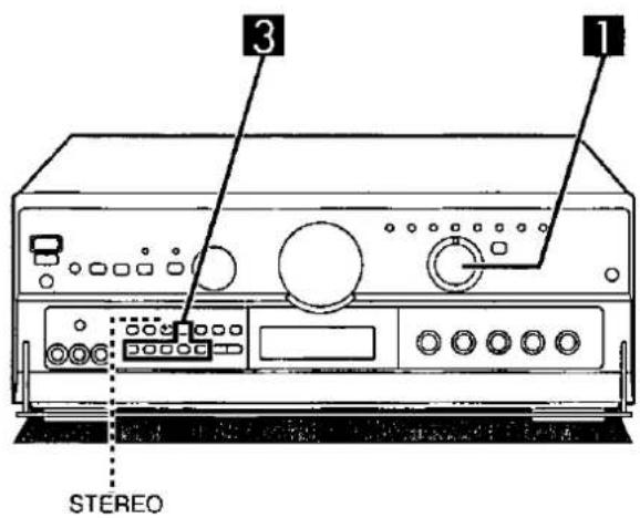
1 Press [-☐☐ PRO LOGIC, -CENTER MODE] to select "SURROUND."
Each time the button is pressed, the Dolby Pro Logic mode will change as follows SURROUND ⇌ 3 STEREO.
Note
- Select "3 STEREO" if surround speakers have not been connected.
- Remember, you cannot adjust the output level of the surround speakers if you selected "3 STEREO" mode.
2 Press and hold [-☐☐PRO LOGIC, -CENTER MODE] to select the correct center mode.
When the button is pressed and held, the current center mode is displayed. Pressing it again changes the center mode.
NORMAL
When the center speaker is smaller than the front speakers. WIDEBAND When the center speaker is the same size as or larger than the front speakers.
PHANTOM SURROUND mode only
When no center speaker is connected.
Note
In the PHANTOM mode, the sound which would have been sent to the center speaker will be divided equally between both the left and right front speakers.
(Continued on next page)

3

4


5
6

7

3
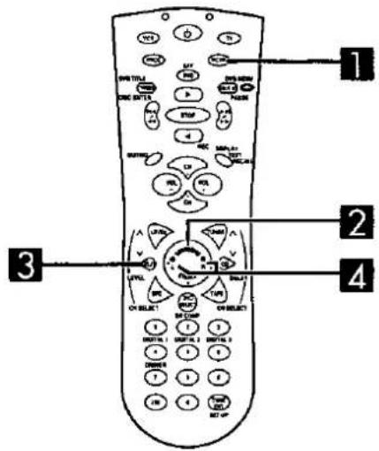
by remote control only
Press [RCVR] to switch to the receiver operation mode.
The button lights up.
4
by remote control only
Press [TEST] to output a test signal.
The speaker outputting the test signal is displayed while the test is running.
L : Front speaker (left)
C: Center speaker
R: Front speaker (right)
S: Surround speakers
The subwoofer is muted while testing.
In the PHANTOM mode, the center speaker is OFF, so there is no center test signal and "C" is not displayed.
5
by remote control
Press [VOL -] or [VOL +] to set the volume level normally used for enjoying the source.
6
by remote control only
Press [LEVEL] to select the center or surround speakers.
7
by remote control only
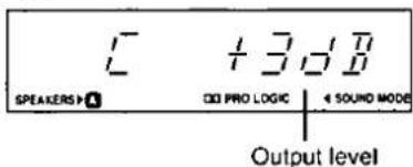
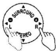
Press [●] or [○] to adjust the output level to the same apparent level as the front speakers.
-: Decrease the output level.
+: Increase the output level.
Output level can be varied within a range of -12 dB to +12 dB with front speaker output level serving as the zero point.
Note
During steps 6 and 7 above the test signal sequence is interrupted and the signal will only come from the selected speaker.
The sequence will resume when adjustments are stopped.
8
Repeat step 6 and 7 for each speaker channel.
To stop the test signal
Press [TEST].
To turn off the Dolby Pro Logic systems
Press [STEREO].
1

2


3


4

A
Front speaker (left)

flowchart
graph TD
    A["Front speaker (right)"] -->|D1| B["Center speaker"]
    C["Surround speaker (right)"] -->|D2| B
    D["Sound speaker"] -->|D1| B
    B -->|D1| E["3D block with cube"]
    B -->|D2| F["3D block with cube"]
Adjusting the delay time
by remote control only
Adjust the sound from the surround speakers until the proper effect is produced.

Press [RCVR] to switch to the receiver operation mode.
The button lights up.

Press [SURROUND].
Note
This procedure can be done only in the SURROUND mode.

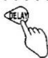
Press [DELAY].
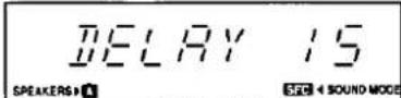
When the button is pressed, the current delay time is displayed.

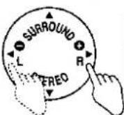
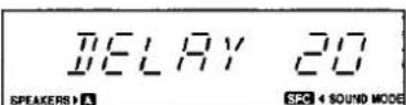
Press [●] or [⊕] to set the time.
The delay time changes by 5 ms with each press, between 15 and 30 ms.
The standard setting is 20 ms.
To calculate the delay time A
D: Distance from front speakers
D2: Distance from surround speakers
- If D_1 is equal to or less than D_2 . Set to 15 ms.
- If D_2 is less than D_1 .
Start at 15 ms and increase by 5 ms for every 1.5 m of difference between D₁ and D₂.


Enjoying sound modes on the receiver
Ensure you have your speakers set up in either of the following ways.
- The front speakers are connected to the A terminals (→ page 14) and "SPEAKERS A" is selected.
- The front speakers are bi-wired (→ page 15) and "SPEAKERS BI-WIRE" is selected.
1 Turn [INPUT SELECTOR] to select the source.
2 Start the source.
3 Select the mode.
The selected reproduction mode appears on the display.
(→ Page 27 for descriptions of the modes.)
To turn off the Dolby Pro Logic or SFC functions Press [STEREO].
For your reference
You can set the sound mode for each source. Each source will retain the selected mode.
Note
- These modes cannot be turned on while SPEAKERS B is on. These modes are automatically switched to STEREO if SPEAKERS B is selected and the modes in the memory for all sources will also be switched to STEREO. The modes must be selected again for all sources when SPEAKERS B is turned off again.
- BI-AMP and Dolby Pro Logic, BI-AMP and any of the SFC modes cannot be used at the same time. If you are using BI-AMP and you select a Dolby Pro Logic or SFC mode, BI-AMP will turn OFF and the "BI-AMP" indicator will go out.
- You cannot select Dolby Pro Logic or any of the SFC modes while in the DVD 6CH INPUT mode.
A

1
2

3

B

1
2
3
Enjoying sound modes
Adjusting field of sound in the SFC mode
by remote control only
With this unit, you can adjust speaker volume.
Adjust the field of sound while listening to a source.
To adjust the volume of each speaker


Press [RCVR] to switch to the receiver operation mode.
The button lights up.

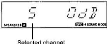
Press [LEVEL] to select the speaker channel to adjust.
The output level appears on the display.
Note
You can adjust center speaker volume only in THEATER mode

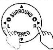
Press [●] or [⊕] to adjust the output level.
Channels C and S can be adjusted between -12 dB and +12 dB.
To adjust the delay time of the surround speakers B

Press [RCVR] to switch to the receiver operation mode.
The button lights up.

Press [DELAY].
When the button is pressed, the current delay time is displayed.

Press [●] or [⊕] to set the time.
Each press changes the delay time.
Increments depend on the mode.
Select a delay time setting to accommodate to your individual needs.
| SFC modes | Available delay time setting (ms) |
| HALL | 20, 25, 30, 40, 50 |
| CLUB | 0, 15, 20, 25, 30 |
| LIVE | 15, 20, 30, 40, 50 |
| THEATER | 15, 20, 25, 30, 40 |
| SIMULATED | 15, 20, 25, 30, 40 |
The figures in bold italics are the factory settings.
For your reference
Settings for volume level and delay time can be done for each SFC mode.


flowchart
graph TD
    A["INPUT SELECTOR"] --> B["VGCA"]
    B --> C["Speaker Selection Logic"]
    C --> D["TONE DEF"]
    D --> E["Speaker Selection Logic"]
VGCA mode
This receiver features a state-of-the-art variable gain control amplifier (VGCA). This feature cuts down greatly on noise encountered during normal use.
1 Turn [INPUT SELECTOR] to select the source.
2 Press [VGCA]. The "VGCA" indicator lights when "VGCA" is selected. "VGCA ON" is displayed, then "TONE DEFEAT / DISPLAY OFF" scrolls across the display. The display then turns off. If TUNER was chosen as the source, the current frequency is shown.
3 Start the desired source. Follow your equipment's operating instructions.
To confirm the current display
Press [STEREO].
The display comes on for about 3 seconds.
For your reference
You can set the VGCA mode for each source.
Each source will retain the selected mode.
Note
- Tone quality (bass and treble) cannot be adjusted in this mode.
- Dolby Pro Logic and the SFC modes cannot be selected while VGCA is on. These modes are also cancelled when VGCA is turned on and STEREO mode is engaged.
To have the display on constantly
The display is turned off while VGCA is on to cut down on unnecessary noise. Do the following if you would prefer to have the display on.
① Turn [INPUT SELECTOR] to select a source other than TUNER.
② Press [VGCA] to turn VGCA on.
③ Press and hold [VGCA] for about 4 seconds until the display comes on.
This setting remains active even if the unit is turned off. Repeat the procedure to turn the display off again.
VCR 2 TV/DSS

A

B
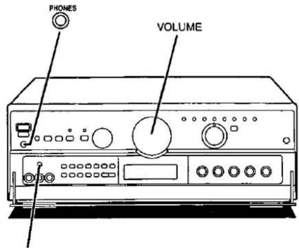
② PHONES

C

TV/DSS

Other functions
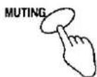
To mute the sound level
A
by remote control only
Press [MUTING].
The message "MUTING ON NOW" runs repeatedly from right to left across the display as long as the muting function is on.
Press once again to return to the previous volume level.
Note
Muting is cancelled when the receiver is turned off.
To listen through headphones
B
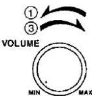
① Reduce the volume level.
② Connect the headphones.
Plug type: 6.3 mm (1/4 in.) stereo
③ Adjust the volume level.
Turn the speakers off when using headphones. Turning the speakers off automatically engages STEREO mode and ensures no sound is heard from the subwoofer. If either SURROUND or 3 STEREO is used, the sound heard through the headphones will seem unusual.
Note
Avoid listening for prolonged periods of time to prevent hearing damage.
When using the VCR 2 terminals (front panel)
C
This button can be used only when TV/DSS/VCR 2 is selected as the input source.
The TV/DSS, VCR 2 input select button works for both TV/DSS input and input from the source connected to the front panel "VCR 2" terminals.
(→ Page 10.)
Select " ■ TV/DSS" or " ■ VCR 2".

A
②

B

②


Other functions
To turn off the blue light on the receiver and dim the processor's display
A
by remote control only
This can improve video viewing in dark or dimly lit rooms.
① Press [PROC].
The button lights up.
② (Point the remote control toward the receiver and processor) Press [DIMMER].
When the button is pressed, the blue light on the receiver is turned off and the display on the processor is dimmed.
Repeat to turn on again.
Note
- When the unit's power is turned off, the original condition is restored.
- If one of the conditions is not changed, turn the system off to return it to the original setting and repeat the steps again carefully.
Setting the midnight mode (dynamic range compression)
B
by remote control only
"Dynamic range compression" (DR COMP) is a function for compressing the dynamic range (reproduction level range) of audio signals. It is used for viewing movie software late at night or at other times when high volume levels are not desirable.
This function only works with DR COMP compatible Dolby Digital format software.
① Press [PROC].
The button lights up.
② Press [DR COMP].
The "DR COMP" indicator lights.
When the procedure is repeated, the function is released, and the indicator goes off.
For your reference
When DR COMP is on, scenes that already have a low sound level will be heard as they are. When scenes that are loud occur, the function acts to reduce the peak level.
The sound field will remain intact even if DR COMP is functioning.


Making a recording
Note
When you select DVD 6CH INPUT mode, only sound from the front left and right channels is recorded.
To record all 6 channels
Set the playback mode on the processor to STEREO mode.
(→ Page 26.)
Recording to a tape deck or VCR
You can record to a tape deck connected to TAPE REC (OUT) or to a VCR connected to VCR 1 OUT.
See the recording unit's operating instructions for details on how to prepare it for recording.
When recording with a tape deck, you can record any source except TAPE.
When recording with a VCR, you can record any source except TAPE or VCR 1.
Note
Recording from the tape deck to the VCR is not possible.
1 Turn [INPUT SELECTOR] to select the source to be recorded.
2 If you selected TV/DSS/VCR 2 in step 1, set [■TV/DSS, □VCR 2] to the required position.
3 Begin recording.
Follow your recording unit's operating instructions.
4 Start the source to be recorded.
Follow your equipment's operating instructions.
To monitor sound being recorded onto a tape deck A
It is possible to check the sound being recorded if your tape deck is a 3 head system.
Press [TAPE MONITOR] on this unit and set the monitor button on the tape deck to "TAPE."
Press [TAPE MONITOR] once again to turn it off.
For your reference
Use the VCR 2 terminals on the front of the unit when dubbing from a video camera.
To operate the receiver
Point the remote control toward the receiver  | Basic operations | |
| To turn on/off | Once the unit has been set to on, it can be turned on and off simply by pressing [ ⏻ ]. | |
| To switch the remote control to each operation mode | SATRCVRRCVR→TUNERorCDOrTAPE | |
| To reconfirm the remote control operation mode | RECALL | |
| To select an input source | VCRRCVR→NotePHONO and VCR 3 can not be selected with this remote control.TAPE MONITOR cannot be controlled with the [TAPE] button. | |
| To mute the sound level | The message “MUTING ON NOW” runs repeatedly from right to left across the display as long as the muting function is on.Press once more to return to the original volume. | |
| To adjust the volume level | VOLVOL | |
| To turn on/off the blue light | The processor's display also dims (brightens) if faced towards the processor at the same time. | |
To operate the receiver (continued)
Point the remote control toward the receiver | Surround modes | ||
| To turn on the Dolby Pro Logic SURROUND mode |  | Note3 STEREO can not be selected with this remote control. | |
| To turn off the Dolby Pro Logic and SFC mode |  | ||
| To turn SFC on and select the mode |  | Changes as follows each time the button is pressed. | |
| To output a test signal | When the SURROUND or 3 STEREO mode is on | Press once more to stop the test signal. | |
| To select the speaker channel and adjust its output level | When the SURROUND, 3 STEREO or SFC modes are on  1 Select center (C) or surround (S).2 Adjust output level.When the SURROUND mode is on and the center mode is on PHANTOM, you cannot select the center channel.When SFC is used, the center mode can be changed only if THEATER is on.When the 3 STEREO mode is on, you cannot select the surround channel. 1 Select center (C) or surround (S).2 Adjust output level.When the SURROUND mode is on and the center mode is on PHANTOM, you cannot select the center channel.When SFC is used, the center mode can be changed only if THEATER is on.When the 3 STEREO mode is on, you cannot select the surround channel. | ||
| To adjust delay time | When the SURROUND or SFC modes are on | ||
| To listen to radio broadcasts | |||
| To select “FM” or “AM” | [GW20] Change as follows each time the button is pressed.FM ⇌ AM | ||
| To select the desired channel sequentially (Preset tuning) | [DSTG] | ||
 | |||
| To select the desired channel directly (Preset tuning) |  2 3 2 3 5 6[SDYH] 8 9 5 6[SDYH] 8 9 0 0 | (Example: Channel 1) [GST3] [GST3]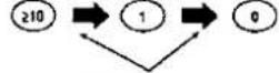  | |
| To select radio stations by frequency (Direct tuning) | [KDSX] 1 2 3 4 5 6 4 5 6 7 8 9 7 8 9 0 0 | (Example: 107.9 MHz) within 10 seconds within 10 seconds | |
To operate the processor
Point the remote control toward the processor | To turn on/standby | |
| To select the input source | ||
| To select the SURROUND mode |  | |
| To select the STEREO mode |  | |
| To output a test signal | When the SURROUND mode is onTESTPress once more to stop the test signal. | |
| To select the speaker channel and adjust its output level | When the SURROUND or DTS mode is on | |
| To select the speaker channel and adjust its delay time | When the SURROUND mode is on | |
| To adjust the volume balance between the left and right front speakers |  | |
| To turn the midnight mode on |  This function only works with DR COMP compatible Dolby Digital format software. This function only works with DR COMP compatible Dolby Digital format software. | |
| To dim the display |  The receiver's blue light also goes off (comes on) if faced towards the receiver at the same time. The receiver's blue light also goes off (comes on) if faced towards the receiver at the same time. |
To operate a cassette deck
Turn the cassette deck ON before trying to operate it by remote control. It may not be possible to operate some cassette decks with this unit.
Point the remote control toward the cassette deck | To switch the remote control to the cassette deck operation mode |  |
| Only when using a double cassette deckTo select the tape deck (DECK 1/DECK 2) |  | |
| To start playback |   | |
| To fast-forward or rewind the tape | While the tape is stopped With TPS-equipped cassette decks, you can move to the beginning or end of a track by pressing these buttons while the tape is playing. With TPS-equipped cassette decks, you can move to the beginning or end of a track by pressing these buttons while the tape is playing. | |
| To stop playback |  |
To operate a CD changer or CD player
Turn the CD changer (or CD player) ON before trying to operate it by remote control. It may not be possible to operate some CD players with this unit.
| Point the remote control toward the CD changer (or CD player) | To switch the remote control to the CD changer (or CD player) operation mode | RCVR → CD |
| To start play | ||
| [CD changer only] To start play from the desired disc | For 5 CD changer1 2 3Select disc number. | |
| For MEGA CD changer※1 2 34 5 67 8 90Select the disc number.(When selecting discs,[≥10] does not respond to touch.) | ||
| To start play from the desired track | 1 2 34 5 67 8 9210 0 | Select the track number.(Example: Track 1)1(Example: Track 10)210 → 1 → 0 |
| To skip a track | ||
| To stop play | STOP | |
* "MEGA CD changer" means any Technics CD changer that takes more than 50 discs.
To watch TV broadcasts
The procedures below are examples for when a TV and VCR are connected to the receiver as shown in this manual.

To watch TV broadcasts
Point the remote control toward the receiver
Point the remote control toward the receiver and the TV
Point the remote control toward the TV

Switch ON the TV
The receiver will switch to TV/DSS/VCR 2 input.

Point the remote control toward the TV

chemical
Molecular structure diagram showing CH and OT groups with numbered positionsSelect the desired channel.
To watch TV broadcasts with a VCR tuner
Point the remote control toward the receiver
Point the remote control toward the TV
Point the remote control toward the TV



Switch ON the receiver.
Switch ON the TV.
Set the TV/VIDEO mode on the TV to "VIDEO".
Point the remote control toward the VCR


Point the remote control toward the VCR and the receiver
Switch ON the VCR.
The receiver will switch to VCR 1 input.
To switch OFF the TV

To switch OFF the VCR

To watch video tapes
The procedures below are examples for when a TV and VCR are connected to the receiver as shown in this manual.
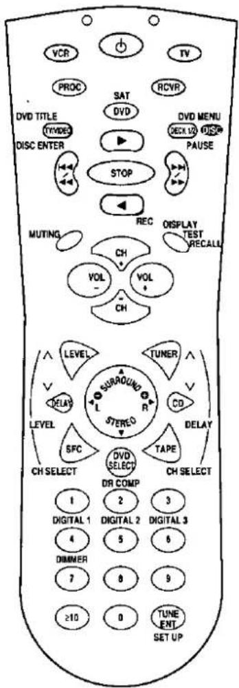 | To watch video tapes | |
| Point the remote control toward the receiverRCVR→→→→→→→→→→→→→→→→→→→→→→→→→→→→→→→→→→→→→→→→→→→→→→→→→→→→→→→→→→→→→→→→→→→→→→→→→→→→→→→→→→→→→→→→→→→→→→→→→→→→ | Point the remote control toward the TV→→→→→→→→→→→→→→→→→→→→→→→→→→→→→→→→→→→→→→→→→→→→→→→→→→→→→→→→→→→→→→→→→→→→→→→→→→→→→→→→→→→→→→→→→→→→→→→→→→→ | |
To operate a DVD player
The procedures below are examples for when a TV and DVD player are connected as shown in this manual. Actual operations depend on your equipment and software.
 | To watch DVDs | ||
| Point the remote control toward the receiverRCVR → 🔍 →Switch ON the receiver. | Point the remote control toward the TVTV → 🔍 → (TV)Switch ON the TV. | Point the remote control toward the TVTOMEDSet the TV/VIDEO mode on the TV to "VIDEO".Point the remote control toward the DVD player. Point the remote control and receiverPlay will begin. Switch ON the DVD player. The receiver will switch to DVD input. | |
| To select the title | DVD TITLESWOODS → (DVD SELECT)Play will begin. | ||
| To use the DVD menu | DVD MENUDECK 10 → (DVD SELECT)Play will begin. | ||
| To clear the DVD menu | DVD MENUDECK 10 | ||
| To use on-screen graphic controls (Graphic user interfaces, GUI, are a feature of some DVD players. See your player's manual for details.) | DISPLAY→ (orDVD SELECT)Play will begin. | ||
| To skip to the beginning of a track or chapter | |||
| To stop play | STOP | ||
| To switch OFF the TV TV → 🔍 To switch OFF the DVD playerDVDDV | |||
To watch satellite broadcasts
The procedures below are examples for when a TV and satellite receiver are connected. To operate the satellite receiver, you must set up the codes. (→ Page 53 and 54.)

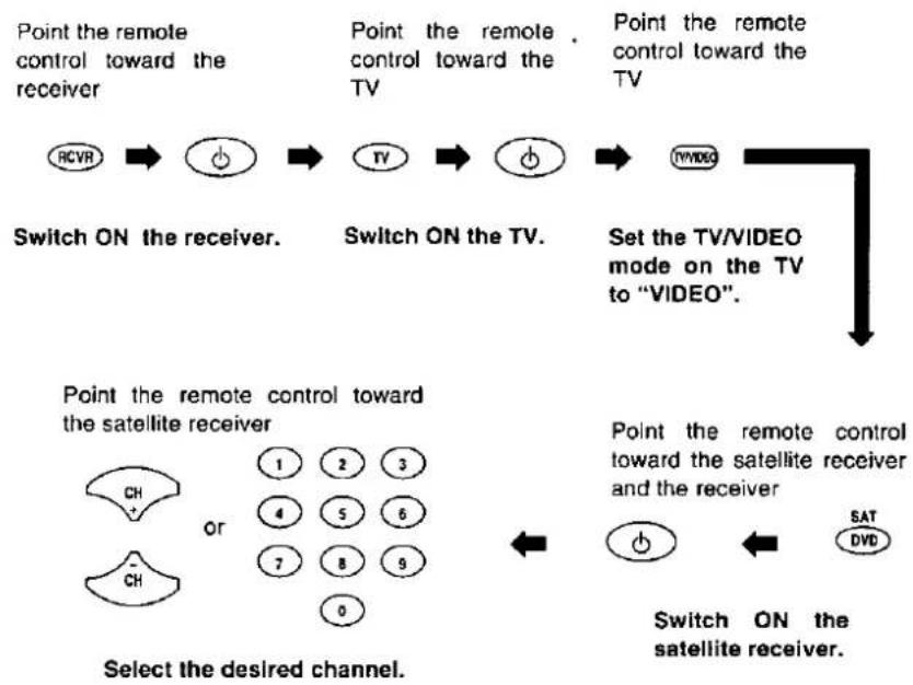
flowchart
graph TD
    A["Point the remote control toward the receiver"] --> B["RCVR"]
    B --> C["Switch ON the receiver."]
    C --> D["Switch ON the TV."]
    D --> E["TV/VIDEO mode on the TV to "VIDEO"."]
    E --> F["Set the TV/VIDEO mode on the TV to "VIDEO"."]
    F --> G["Point the remote control toward the satellite receiver"]
    G --> H["Select the desired channel."]
    H --> I["1 2 3"]
    H --> J["4 5 6"]
    H --> K["7 8 9"]
    H --> L["0"]
    G --> M["1 2 3"]
    G --> N["4 5 6"]
    G --> O["7 8 9"]
    G --> P["SAT DVD"]
    G --> Q["Switch ON the satellite receiver."]
To switch OFF the TV

To switch OFF the satellite receiver
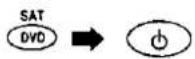
To watch cable TV
The procedures below are examples for when a TV and cable box are connected. To operate the cable box, you must set up the codes. (→ Page 53 and 54.)


flowchart
graph TD
    A["Point the remote control toward the receiver"] --> B["Switch ON the receiver."]
    B --> C["Switch ON the TV."]
    C --> D["Set the TV/VIDEO mode on the TV to "VIDEO"."]
    D --> E["Point the remote control toward the cable box"]
    E --> F["Switch ON the cable"]
    F --> G["SAT DVD"]
    style A fill:#f9f,stroke:#333
    style B fill:#ccf,stroke:#333
    style C fill:#cfc,stroke:#333
    style D fill:#fcc,stroke:#333
    style E fill:#cff,stroke:#333
    style F fill:#ffc,stroke:#333
    style G fill:#fcf,stroke:#333
Select the desired channel.
Point the remote control toward the cable box and receiver

Switch ON the cable box.
The receiver will switch to DVD input.
To switch OFF the TV

To switch OFF the cable box

Changing the remote control code
Change the remote control code in either of the following circumstances:
- If the Panasonic TV or VCR does not operate as a result of a difference in the remote control code.
- If you wish to operate some other make of TV, VCR, DVD player, satellite receiver or cable box.
(→ Refer to pages 48 to 52 for the buttons which can be used.)
Note
- Even after changing the code there may be cases where certain operations cannot be done or operation is not possible at all.
- Changes to the codes may be cancelled when the remote control's batteries are replaced. Repeat the operation to reenter the code.
- This remote control can only accept the code for either a DVD player or a satellite receiver or a cable box. It will be able to control only the component you have entered the code for.

How to change the remote control code
Find the code numbers for your device in the code tables. (→ pages 55 to 59).
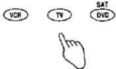
2 Press the button for the component you want to operate.
3 Press [SET UP]. Both the green and red indicator light up.

4 Press the button for the component you want to operate again.
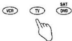
5 Carefully enter the 4 digit code. The buttons at the top of the remote control flash to indicate the number has been accepted. Repeat from step 2 if the number wasn't accepted.

6 Press [☐] to test operation. If the correct code was entered, the component will turn on or off. Try the code. If the component doesn't respond, repeat from step 2 and try the next code.

Changing the remote control code (continued)

Using the code scan to change the remote control code

Press [SET UP].
Both the green and red indicator light up.


Press the button for the component you want to operate.
Only the red indicator lights up.


Press [0] twice.


Press [∅] repeatedly until the component responds.
Be sure to leave enough time between presses for the component to respond.

Press [SET UP] immediately after the component responds.
The code is locked into the remote control.


Press [⏻] again to check that the code has been accepted.

For your reference
Checking the code numbers you have entered.
Use this feature to make a note of the codes you have entered for each component.
① Press [SET UP].
Both the green and red indicators light up.
② Press the button for the component you want to confirm.
Only the red indicator lights up.
③ Press [≥10].
The green indicator flashes to show the code number. It pauses between each digit. 10 flashes represents "0".
The red indicator goes out to show the number is finished.
TV code lists
A Mark
4100
Action
4013
Admiral
4132 4052 4053 4077 4085 4084
Advent
4159
Akai
4075 4066 4009 4000
Anam
4011
Anam National
4017
AOC
4024 4000 4006 4042 4100 4122 4129
Audiovox
4013
Baycraft
-Also see Baycrest
4060 4059 4042 4084
Bell & Howell
4053 4132 4052 4085
Broksonic
4053 4067 4113 4000 4002 4011 4114
Candle
-Also see Citizen
4086 4053 4069 4059 4129 4100 4101
4148 4000 4011 4024 4042 4051 4058
4114 4116
Citek
4149
Citizen
-Also see Candle
4086 4114 4148
Classic
4066 4000
Colortyme
4053 4069 4044 4077 4115 4009 4018
4096 4097 4105 4090
Concherto
4053
Contec Cony
4013 4011 4109 4046 4073
Craig
4069 4013 4114 4011 4035 4056 4059
Crosley
4053
Crown
4059 4100
Curtis
4000 4090 4123
Curtis Mathes
4133 4053 4132 4069 4077 4070 4009
4024 4042 4100 4101
CXC
4013 4011
Daewoo
-Also see Funal/Goldstar/Magnasonic/
Nikko
4142 4086 4130 4129 4024 4017 4100
4150 4000 4042 4090 4101 4123
Daytron
4100 4035 4042 4123 4129
Denon
4152
Electrohome
4075 4099 4100 4000 4003 4009 4042
4062
Emerson
4054 4069 4013 4012 4153 4043 4085
4084 4011 4000 4083 4071 4154 4004
4038 4155 4100 4003 4009 4016 4035
4042 4046 4056 4058 4059 4072 4073
4109 4113 4115 4150
Envision
4024 4009
Fisher
-Also see LXI/Sanyo/Sears
4093 4066 4068 4039 4047 4107 4088
Fortress
4009
Funai
-Also see Daewoo/Goldstar/
Magnasonic/Nikko
4013 4029 4011 4058 4158
Futuretech
4011
Garrard
4158
GE
4133 4069 4076 4134 4063 4077 4080
4025 4017 4027 4040 4000 4006 4008
4011 4019 4026 4028 4042 4100 4124
4150
Goldstar
-Also see Daewoo/Funai/Magnasonic/
Nikko
4052 4014 4134 4106 4122 4000 4024
4121 4009 4042 4100 4112 4051 4101
4105
Gradiente
4065
Granada
4060 4100 4105
Grundig
4076 4043 4139 4057 4079 4100
Hallmark
4000
Harley Davidson
-Also see RCA
4077
Harman Kardon
4000
Hitachi
4152 4118 4060 4076 4077 4100 4119
4129 4072 4099 4010 4031 4033 4036
4042 4085
Infinity
4105
Inteq
-Also see Zenith
4052 4050
JBL
4105
JC Penney
4069 4076 4077 4028 4024 4025 4000
4006 4106 4107 4055 4100 4121
Jensen
-Also see NEC
4009 4083
JVC
4086 4074 4069 4076 4048
Kawasho
4066 4024 4109 4098
Kenwood
4009 4115 4000 4024 4040 4078 4096
Kloss Novabeam
4017 4125
KMC
4100
KTV
4143 4013 4109 4016 4100 4011 4024
4042
Lloyds
4115 4099 4112
Logik
4052 4132 4138 4137
LXI
-Also see Fisher/Sanyo/Sears
4133 4053 4077 4000 4106 4158 4028
Magnasonic
-Also see Daewoo/Funai/Goldstar/
Nikko
4085 4000 4009 4058 4129
Magnavox
4053 4086 4076 4043 4125 4090 4009
4105 4082 4085 4000 4015 4042 4116
4003 4021 4024 4035 4049 4058 4059
4103 4104 4108 4110
Marantz
4053 4043 4009 4024 4040 4042 4105
4106
Matsushita
-Also see Panasonic
4091
Megatron
-Also see Hitachi
4060
Memorex
4132 4000 4001 4034 4062 4088 4099
4106 4156
MGA
-Also see Mitsubishi
4075 4132 4062 4009
Mitsubishi
-Also see MGA
4075 4151 4062 4099 4000 4127 4009
4005 4024 4001 4036 4042 4091 4100
4105 4111 4117
MTC
4053 4069 4024 4129 4000 4018 4088
4109 4125
Multivision
4143 4081
NAD
4034
NEC
4043 4042 4009 4096 4115 4024 4040
4097
Nikko
-Also see Daewoo/Funai/Goldstar/
Magnasonic
4129
TV code lists
Nishi
4069
Nyon
4028 4000
Onwa
4011
Optimus
-Also see Radio Shack/Realistic 4126
Orion
4153 4084
Panasonic
-Also see Matsushita
4142 4118 4076 4013 4070 4077 4080
4043 4017 4117 4027 4030 4056 4055
4025 4057 4092 4129 4140 4148 4158
Philco
4053 4086 4043 4090 4085 4009 4015
4059 4125 4000 4003 4021 4024 4035
4042 4058 4082 4103 4104 4105 4108
4110 4129
Philips
4053 4086 4105
Pioneer
4023 4043 4126 4120 4017 4040 4042
Portland
4100 4101 4000 4024 4042 4123
Prima
4101 4138
Prism
4043
Proscan
-Also see RCA
4133 4134 4077
Proton
4077 4000 4100 4009 4114 4007 4018
4033 4042 4059 4095 4106
Pulsar
4129 4000 4018 4042 4106 4112 4113
Quasar
4142 4118 4076 4080 4043 4017 4030
4117 4035 4055 4057 4092 4119
Radio Shack
-Also see Optimus/Realistic
4053 4013 4077 4068 4061 4011 4034
4017 4020 4032 4087 4099 4100 4141
RCA
-Also see Proscan
4133 4023 4069 4134 4063 4077 4080
4028 4006 4017 4092 4011 4025 4026
4027 4040 4042 4100 4124
Remocon
4101
Rent-Co
4090
Runco
4132 4148
Sampo
4118 4017 4024 4042
Samsung
4069 4074 4157 4024 4100 4000 4042
4085 4102
Sansui
4061
Sanyo
-Also see Fisher/LXI/Sears
4068 4039 4088 4022 4047 4107
Scott
4054 4013 4100 4011 4042 4058 4082
4084
Sears
-Also see Fisher/LXI/Sanyo
4093 4133 4053 4060 4077 4068 4039
4028 4047 4000 4107 4011 4022 4045
4016 4088 4100
Sharp
4135 4041 4061 4087 4128 4020 4033
4090 4116 4100 4047 4085 4089 4094
4099 4115 4122
Signature 2000
4132 4087 4039
Silver
4000 4009
Simpson
4000 4009
Sony
4064 4066 4041 4144 4098 4100
Soundesign
4059 4000 4003 4011 4042 4072 4083
sss
4009 4011 4024
Sylvania
4053 4086 4043 4090 4104 4009 4108
4015 4110 4059 4125 4021 4082 4000
4003 4024 4035 4042 4045 4058 4103
4105 4116 4129
Symphonic
4012 4013 4029 4158 4058
Tandy
4053
Tatung
4017 4037 4114
Technics
-Also see Panasonic
4118 4076 4080 4043 4117 4145 4057
4092
Teckwood
4053 4009
Teknika
4132 4013 4059 4011 4024 4149 4040
4042 4100 4112 4129
Telefunken
4115
TMK
4009 4000 4115
Toshiba
4093 4086 4069 4107 4111 4039 4106
4131
Totevision
4077
Ultra
4129
Video Concepts
4091 4011
Videokron
4136 4147 4146
Vidikron
4053 4136
Vidtech
4024
Viewmax
4101
Wards
4132 4086 4050 4053 4069 4077 4061
4025 4000 4024 4085 4090 4042 4104
4020 4026 4058 4059 4106
XR 1000
4132 4158
Yamaha
4043 4024 4059 4115 4129
Zenith
4052 4050 4132 4044 4014 4129 4158
VCR code lists
Action
6103
Admiral
6101
Aiwa
6028
Akai
6025 6011 6016 6049 6059
Beaumark
6010
Bell & Howell
6058
Broksonic
6054 6075 6124 6066 6117 6004 6093
6095 6123
Candle
-Also see Citizen
6043 6103 6014 6027 6028 6040 6004
6010 6023 6024 6056 6072
Canon
6027 6109
Capehart
6024 6104
Citizen
-Also see Candle
6014 6027 6028 6040 6072
Colortyme
6081 6096 6027 6080
Craig
6031 6043 6108 6120
Criterion
6031
Curtis Mathes
6027 6014 6081 6109 6040 6006 6010
6023 6028 6051 6082 6094
Daewoo
-Also see Funai/Goldstar/
Magnasonic/Nikko
6005 6103 6014 6104 6024 6023 6099
Daytron
6103 6024 6104
Denon
6038
Dynatech
6014 6065
Electrohome
6067 6013 6043 6122 6004 6053
Emerson
6075 6054 6007 6043 6124 6013 6014
6066 6081 6088 6018 6095 6125 6023
6028 6037 6071 6078 6097 6004 6053
6055 6058 6117 6123 6126
Fisher
-Also see LXI/Sanyo/Sears
6069 6014 6108 6062 6015 6039 6058
6065
Funai
-Also see Daewoo/Goldstar/
Magnasonic/Nikko
6057 6028 6072
Garrard
6028
GE
6019 6081 6027 6068 6040 6010 6082
6092 6097
Genexxa
6028
Go Video
6019 6020 6031 6032 6116 6118 6010
Goldstar
-Also see Daewoo/Funai/Magnasonic/
Nikko
6048 6043 6007 6128 6008 6010 6041
6056
Gradiente
6035
Granada
6013 6004 6053
Hitachi
6012 6038 6063 6119 6028 6040 6092
6065 6113
Homeline
6043
JBL
6086
JC Penney
6038 6031 6043 6027 6010 6070
Jensen
6050 6052
JVC
6035 6012 6047 6038 6096 6074 6050
6078 6003 6026 6058 6097
Kenwood
6069 6006 6050 6058 6094
Lloyds
6028 6094 6057 6072 6108
Loglk
6031 6079
LXI
-Also see Sears/Sanyo/Fisher
6057 6028
Magnasonic
-Also see Daewoo/Funai/Goldstar/
Nikko
6031 6043 6103
Magnavox
6035 6017 6031 6027 6068 6014 6096
6109 6004 6082 6028 6033 6055 6071
6074
Magnin
-Also see MGN
6010
Marantz
6017 6004 6045 6056 6082 6094
Marta
6043
Matsui
6028
Matsushita
-Also see Panasonic
6027
MEI
6065
Memorex
6085 6048 6038 6043 6046 6108 6000
6022 6058
MGA
-Also see Mitsubishi
6013
MGN
-Also see Magnin
6010
Midland
6072
Minolta
6038
Mitsubishi
-Also see MGA
6067 6127 6013 6122 6043 6034 6053
6112 6083 6090
MTC
6031 6028 6057
Multitech
6028 6057
NEC
6048 6007 6091 6096 6094 6056 6028
6045 6006 6050 6051 6065 6074 6078
Optimus
-Also see Radio Shack/Realistic
6061 6043 6128 6121
Panasonic
-Also see Matsushita
6129 6043 6031 6027 6068 6109 6096
6107 6014 6081 6082 6071 6073 6108
6110 6130
Pentax
6038 6094
Philco
6017 6027 6068 6004 6028 6033 6057
6082
Philips
6014 6027 6068 6004 6033 6082
Pioneer
6106 6009 6033 6121
Portland
6024 6104
Pro Max
6128
Proscan
-Also see RCA
6105 6081 6107
Proton
6031
Pulsar
6128 6027 6103 6010 6072 6028 6098
Quasar
-Also see Technics
6043 6129 6068 6027 6109 6081 6082
6115
Radio Shack
-Also see Optimus/Realistic
6043
RCA
-Also see Proscan
6038 6089 6105 6013 6069 6131 6081
6107 6068 6027 6096 6040 6073 6092
6010 6003 6009 6074 6076 6077 6099
Realistic
-Also see Optimus/Radio Shack
6085 6061 6043 6027 6108 6028 6030
6002 6010 6053 6062 6082
Samsung
6128 6010 6040 6072 6028 6073
Sansui
6031 6074 6095
Sanyo
-Also see Fisher/Sears
6085 6069 6108 6058 6015 6039 6062
Scott
6043 6054 6075 6014 6018 6071
VCR code lists
| Sears-Also see Fisher/Sanyo6085 6038 6043 6069 6027 6014 60396028 6015 6058 6062 6108 6045 60746083 6102Sharp6061 6046 6101 6030 6002 6051 60536076Shintom6031Signature 20006085 6101Singer6031Sony6086 6087 6029 6021 6016 6065 60846113 6044 6064 6098 6050Sylvania6027 6109 6028 6004 6057 6082 60336071 | Symphonic6028 6057 6050 6108 6002 6045 6072Tatung6050 6074Teac6028Technics6027 6096 6110 6111Teknika-Also see Panasonic6043 6027 6028 6076Thomas6028TMK6023Toshiba6013 6014 6103 6100 6114 6015 60366060 6084 6108Totevision6043 6109 | Ultra6104Unitec6072 6073Vector Research6094Video Concepts6083 6094Wards6061 6043 6014 6046 6028 6030 60026004 6010 6053 6108XR 10006031 6028Yamaha6050 6094Zenith6048 6047 6025 6043 6040 6059 6057 |
DVD player code lists
| Denon | Panasonic | Sony |
| 6132 | 6132 | 6135 |
| Faroudja | Proscan | Toshiba |
| 6133 | -Also see RCA | 6133 |
| Magnavox | 6134 | Yamaha |
| 6133 | RCA | 6132 |
| Mitsubishi | -Also see Proscan | Zenith |
| 6133 | 6134 | 6133 |
| Onkyo | Samsung | |
| 6133 | 6133 |
SAT code lists
| Alphastar | HTS | RCA |
| 3064 3028 | 3041 | 3051 |
| Birdview | Hughes | Realistic |
| 3026 | 3058 3024 3018 | 3014 |
| Chaparral | Intersat | Rural Cable |
| 3043 3019 | 3042 | 3004 |
| CI Satellite | Janeil | Samsung |
| 3025 | 3011 | 3064 |
| Datron | Kenwood | Sony |
| 3056 | 3013 | 3056 |
| DISH Network | Legend | Star Trak |
| 3061 | -Also see Echostar | 3055 3054 3010 3009 |
| Drake | 3020 | STS |
| 3053 3047 3044 3037 3035 3031 3023 | M/A Com | 3007 |
| 3001 | 3015 3008 3002 3001 | SuperGuide |
| DX Communications | ORB | 3029 3017 |
| 3045 3033 | 3027 | Tee-Com |
| Echostar | Panasonic | 3057 |
| -Also see Legend | 3062 3000 | Toshiba |
| 3049 3048 3040 3032 3020 | Pansat | 3060 3015 3001 |
| Equus | 3052 3022 | Uniden |
| 3038 | Primestar | 3063 3039 3036 3034 3030 3021 3017 |
| Fujitsu | 3033 | 3016 3014 3012 3005 3003 |
| 3011 | Proscan | Video Pall |
| GE | 3051 | 3011 |
| 3051 | Quick Draw | Viewstar |
| General Instruments | 3045 | 3050 |
| 3046 3015 3008 3006 3004 | Radio Shack | Zenith |
| Hitachi | 3014 3006 3004 | 3011 |
CBL code lists
ABC
2013 2016 2018 2053 2010 2011 2030 2031 2034 2038 2048
AIM
2047
Archer
2049 2034 2060
Belcor
2060
BRX
2046
Cableview
2043
Century
2034
Citizen
2049 2027 2034 2047
Contec
2005 2015 2021 2028 2053 2041 2012
2014 2038 2042
CPI
2040
Diamond
2041
Eagle
2031
Eastern
2006
GC Electronics
2049 2058 2019 2027 2034 2052
Gemini
2047 2039 2043 2076
General Instruments
2050 2016 2028 2070 2022 2048
Hamlin
2041 2073 2017
Hitachi
2046 2048
Jasco
2049
Jerrold
2009 2016 2028 2050 2040 2015 2048
2045 2031 2022 2023 2057 2059
JVC
2009
Magnavox
2002 2048
Memorex
2020 2031 2034 2038 2075
Micro Com
2078
Monarch
2027
Movie Time
2013 2033 2027 2034
Northcoast
2036
NSC
2013 2004 2012 2033 2034
Oak
2012 2038 2025 2041 2079
Panasonic
2020 2005 2014 2037
Paragon
2020 2031 2034
Philips
2054 2056 2072 2044 2001 2024 2031
2034 2055 2061
Pioneer
2030 2037
Proscan
2068
Pulsar
2027 2049
Radio Shack
2034 2049 2060
RCA
2068
Recoton
2069
Regal
2041
Regency
2042
Rembrant
2012
Samsung
2027 2030
Scientific Atlanta
2066 2053 2021 2077 2010 2080
Sears
2046
Signal
2027
Signature 2000
2048
Sony
2003
Sprucer
2014 2036
Starcom
2016 2018 2050 2048 2032 2047 2023
2026 2044 2070 2071 2075
Stargate
2047 2027
Sylvania
2029 2046 2065
Telecaption
2067
Tele View
2027
Texscan
2062 2029 2065
Tocom
2013 2000 2011 2033 2010 2012 2014
U.S.Electronics
2053 2018 2048
Unika
2034
United Cable
2016
Universal
2069 2051 2071 2034 2049 2060
Viewstar
2064 2031 2035 2055 2063 2010
Wards
2048
Warner
2030
Wave Master
2008
Zenith
2020 2036 2074
A
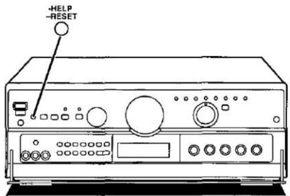

B

natural_image
Line drawing of a portable electronic device with control panel and buttons (no text or symbols)②
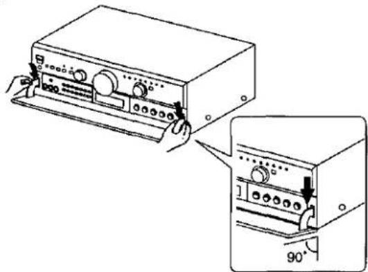
natural_image
Technical line drawing of a device with two views: one showing front view and one showing side view, both without any text or symbols.About the HELP function A
If you make a mistake in operation or if sound output stops due to some operation which was performed, the HELP function displays information which can be useful for indicating the method by which this condition can be remedied.
If "ERROR" or scrolling characters (for instance, "SPEAKER OFF NOW") appear on the display during operation, carry out the following operation.
Press [-HELP, -RESET].
The method for remedying this situation will be displayed.
For your reference
If the above button is pressed for 2 seconds or more until "RESET" appears on the display, the operation settings for the unit will be initialized to the settings made at the time of shipment. However, any broadcasting stations which have been preset into memory will not be erased at this time.
If the front cover comes off ☐
① Insert the cover as shown in the illustration.
② Ensure the cover is parallel to the unit, then press firmly down on the levers until they click into place.
③ Check that the cover now moves correctly. If it does not, remove it and repeat the above procedure.
RECEIVER
AMPLIFIER SECTION
Rated minimum sine wave RMS power output
20 Hz–20 kHz both channels driven
0.05 % total harmonic distortion
100 W per channel (6 Ω)
1 kHz continuous power output both channels driven
0.05 % total harmonic distortion 105 W per channel (6 Ω)
Total harmonic distortion
rated power at 20 Hz–20 kHz 0.05 % (6 Ω)
half power at 1 kHz 0.03% (6 Ω)
Power output at the DVD 6CH operation
20 Hz–20 kHz (each channels driven)
0.09 % total harmonic distortion
Front 2 x 100 W (6 Ω)
Center 100 W (6 Ω)
Surround 2 x 100 W (6 Ω)
Subwoofer 20–200 Hz 100 W (6 Ω)
Low frequency damping factor
Load impedance
Front
A or B 4-8 Ω
A and B 8 Ω
BI-WIRE 6-8 Ω
Center 6-8 Ω
Surround 6-8 Ω
Subwoofer 6-8 Ω
Dynamic headroom
2 dB (8 Ω)
Frequency response
PHONO RIAA standard curve ±0.8 dB
CD, TAPE, DVD, VCR 1, TV/DSS/VCR 2, VCR 3
10 Hz-100 kHz, ±3 dB
Input sensitivity
PHONO 0.4 mV (3 mV, IHF'66)
CD, TAPE, DVD, VCR 1, TV/DSS/VCR 2, VCR 3
27 mV (200 mV, IHF'66)
S/N (IHF A) (VGCA ON)
PHONO 80 dB (80 dB, IHF'66)
CD, TAPE, DVD (L/R/C/LS/RS), VCR 1, TV/DSS/VCR 2, VCR 3
90 dB (100 dB, IHF'66)
110 dB (IHF A, Rated Power, S=2 V)
Input impedance
PHONO 47 kΩ
CD, TAPE, DVD, VCR 1, TV/DSS/VCR 2, VCR 3 22 kΩ
Tone controls
BASS 50 Hz, +10 to -10 dB
TREBLE 20 kHz, +10 to -10 dB
Adaptive control (volume at -30 dB) 50 Hz, +5 dB
Subwoofer cut off frequency control 50–200 Hz
FM TUNER SECTION
Frequency range 87.9–107.9 MHz
Sensitivity 11.2 dBf (2 μV, IHF'58)
50 dB quieting sensitivity
MONO 18.3 dBf (4.5 μV, IHF'58)
STEREO 38.3 dBf (45 μV, IHF'58)
Total harmonic distortion
MONO 0.2%
STEREO 0.3%
S/N
MONO 73 dB
STEREO 67 dB
Frequency response 20 Hz–15 kHz, +1 dB, -2 dB
Alternate channel selectivity 65 dB
Capture ratio 1.5 dB
Image rejection at 98 MHz 40 dB
Spurious response rejection at 98 MHz 75 dB
AM suppression 50 dB
Stereo separation
1 kHz 40 dB
10 kHz 30 dB
Antenna terminal 75 Ω (unbalanced)
AM TUNER SECTION
Frequency range 530–1710 kHz
Sensitivity 20 μV, 330 μV/m
Selectivity 55 dB
IF rejection at 1000 kHz 50 dB
VIDEO SECTION
Output voltage at 1 V input (unbalanced) 1±0.1 Vp-p
Maximum input voltage 1.5 Vp-p
Input/output Impedance 75 Ω
GENERAL
Power supply AC 120 V, 60 Hz
Power consumption 340 W
(In standby condition: 2 W)
Dimensions (W x H x D) 430 x 158 x 378.4 mm
(16-15/16" × 6-7/32" × 14-29/32")
Weight 11 kg (24.4 lb.)
■ DIN Power (1 kHz T.H.D. 1%)
2×100 W (6 Ω)
SURROUND PROCESSOR
AUDIO
Output voltage/Impedance 2 V (at 0 dB)/1 kΩ
Input impedance
LINE 22 kΩ
COAXIAL 75 Ω
Frequency response
FRONT L/R, CENTER, SURROUND L/R (LARGE)
20 Hz–20 kHz ±1 dB
Delay time
DOLBY DIGITAL CENTER 0-5 ms
SURROUND L/R 0–15 ms
DOLBY PRO LOGIC SURROUND L/R 15-30 ms
Total harmonic distortion
FRONT L/R (1 kHz, 0 dB, PCM) 0.007 %
Dynamic range 96 dB
S/N (IHF A) 100 dB
Load impedance More than 10 kΩ
GENERAL
Power supply AC 120 V, 60 Hz
Power consumption 15 W
(In standby condition: 4 W)
430×69.4×301.4mm
(16-15/16" x 2-47/64" x 11-55/64")
Weight 2.6 kg (5.7 lb.)
Notes:
- Specifications are subject to change without notice.
Weight and dimensions are approximate.
- Total harmonic distortion is measured by the digital spectrum analyzer.
Before requesting service for this unit, check the chart below for a possible cause of the problem you are experiencing. Some simple checks or a minor adjustment on your part may eliminate the problem and restore proper operation. If you are in doubt about some of the check points, or if the remedies indicated in the chart do not solve the problem, refer to the directory of Authorized Service Centers (enclosed with this unit) to locate a convenient service center, or consult your dealer for instructions.
For detailed instructions, contact an authorized servicenter in the U.S.A. and Panasonic Canada Inc. Customer Care Centre in Canada. In the U.S.A. 1-800-211-7262 or web site (http://www.panasonic.com) In Canada 905-624-5505 or web site (www.panasonic.ca)
| Problem | Probable cause(s) | Suggested remedy | Page(s) |
| While listening to FM broadcasts | |||
| Hiss is heard during stereo broadcasts, but not during monaural ones. | Modulation for the two types is different so some noise may be heard during stereo broadcasts. | Reduce the treble.Change the location and direction of the antenna.Use an outdoor antenna.Use an antenna with more elements. | 2012,1313- |
| Excessive noise in both stereo and monaural broadcasts. | Antenna location and direction poor. | ||
| Station is distant. | |||
| “STEREO” and “TUNED” indicators flicker. | Antenna location and direction poor. | Change the location and direction of the antenna.Use an outdoor antenna.Use an antenna with more elements. | 12,1313- |
| Station is distant. | |||
| Stereo broadcasts highly distorted. | Building or mountain nearby. | ||
| While listening to AM broadcasts | |||
| Unusual “beat” sound is heard. | A television is on nearby. | Separate the two or turn the television off. | - |
| Adjacent signal is interfering. | Reduce the treble. | 20 | |
| Low-pitched “hum” is heard when a station is tuned. | Power cord is near the antenna wires. | Separate the power cord from the wires. | - |
| Electronic interference from the power cord is fed to the speakers. | Use an outdoor antenna. | 13 | |
| A continuous or intermittent hiss is heard. | Interference from other appliances. | Separate this unit from such appliances. | - |
| While enjoying the surround modes | |||
| Sound is not heard from the center, surround or subwoofer speakers. | The presence setting of the speaker has been incorrectly set to "NONE" or "NO." | ● Set the type and presence setting of each speaker correctly. | 28 |
| The STEREO reproduction mode is on. | ● Set to SURROUND or DTS reproduction mode. | 33 | |
| A DTS formatted source cannot be played back in the SURROUND mode. | This DTS source couldn't be processed by the SURROUND mode. | ● Select the DTS reproduction mode. | 33 |
| Sound doesn't come from the center speaker while using Dolby Pro Logic. | PHANTOM is selected. | ● Select NORMAL or WIDEBAND. | 34 |
| Problem | Probable cause(s) | Suggested remedy | Page(s) |
| Common Problems | |||
| Unit doesn't come on. | The power cord plug is not fully inserted. | ● Confirm the plug is fully inserted. | - |
| Sound Is not heard. | The speaker indicators are off. | ● Turn on the speaker indicators. | 18 |
| The tape monitor function is on. | ● Press the tape monitor button. | 19 | |
| The muting function is on. | ● Press the muting button on the remote control. | 40 | |
| Incomplete or incorrect connection to speakers and external equipment. | ● Check all connections. | 8-11, 14-16 | |
| The incorrect input source has been selected. | ● Select the correct source. | 18, 32 | |
| The midnight mode does not function. (When the DR COMP button on the remote control is pressed, the DR COMP indicator does not light.) | The SURROUND mode has not been selected. | ● Select the SURROUND mode. | 33 |
| The source being played has not been recorded in the Dolby Digital format. | ● Check if the ☐ DIGITAL indicator is illuminated. | 41 | |
| Sound suddenly stops or none is heard when the unit is switched on. "OVERLOAD" appears on the display. | The protection circuitry has functioned because: the positive and negative speaker wires have shorted; speakers with a lower impedance than this unit's rated impedance are being used; the speakers are under strain through excessive volume, excessive power, or by being used in a high temperature environment. | ● Switch off the unit, determine and correct the cause, then switch the unit on.● Use speakers with the right impedance rating. | -15-16 |
| "F70" appears on the processor's display. | ● Turn off the power and then turn it on again, or disconnect the AC power supply cord and then connect it to your household AC outlet again.(If "F70" still remains on the display, consult an authorized service center or your dealer.) | - | |
Listening caution


Selecting fine audio equipment such as the unit you've just purchased is only the start of your musical enjoyment. Now it's time to consider how you can maximize the fun and excitement your equipment offers. This manufacturer and the Electronic Industries Association's Consumer Electronics Group want you to get the most out of your equipment by playing it at a safe level. One that lets the sound come through loud and clear without annoying blaring or distortion—and, most importantly, without affecting your sensitive hearing.
We recommend you to avoid prolonged exposure to excessive noise.
Sound can be deceiving. Over time your hearing "comfort level" adapts to higher volumes of sound. So what sounds "normal" can actually be loud and harmful to your hearing.
Guard against this by setting your equipment at a safe level BEFORE your hearing adapts.
To establish a safe level:
- Start your volume control at a low setting.
- Slowly increase the sound until you can hear it comfortably and clearly, and without distortion.
Once you have established a comfortable sound level:
- Set the dial and leave it there.
Taking a minute to do this now will help to prevent hearing damage or loss in the future. After all, we want you listening for a lifetime.
Maintenance
If the surfaces are dirty
To clean this unit, wipe with a soft, dry cloth.
If the surfaces are extremely dirty, use a soft cloth dipped in a soap-and-water solution or a weak detergent solution.
- Never use alcohol, paint thinner or benzine to clean this unit.
- Before using chemically treated cloth, read the instructions that came with the cloth carefully.
Product service
Do not attempt to remove the cover(s) or repair the unit yourself. Refer servicing to qualified personnel only.
Product information
For product service, product information or assistance with product operation, refer to the servicenter directory.
- Digital Surround Processor AV Control Stereo Receiver
- SF-DX7
- Technics®
- Dear Customer
- Enjoying DVD and other digital sources
- CAUTION
- Table of contents
- Supplied accessories
- CAUTION:
- WARNING:
- Safety
- Installation
- Environment
- Placement
- Maintenance
- Service
- Surround system
- Dolby Pro Logic
- Features
- Software
- Dolby Digital (AC-3)
- DTS
- SFC (Sound Field Control)
- Speaker indicators
- Signal format indicators (LS, C, RS, L, R, S, LFE)
- Note
- Connecting the receiver and processor
- "UNSWITCHED" AC outlet
- Connecting a DVD player and other digital equipment
- Optical fiber cable connections A
- "DIGITAL 1" terminals B
- "LINE IN" terminals ©
- Connections to/from S-VIDEO
- Caution when using a TV with an S-VIDEO terminal
- Antenna connections
- FM indoor antenna (included)
- AM loop antenna (included)
- When mounting the antenna to a column, a wall or rack C
- FM outdoor antenna (not included)
- AM outdoor antenna (not included)
- Placement of speakers
- Front speakers
- Center speaker
- Surround speakers
- Subwoofer
- Connecting speakers
- Bi-wiring connection
- Other speakers
- Concerning the remote control
- Battery installation
- Use of batteries
- Correct method of use
- Operation notes
- To prevent damage
- Basic operations
- Press [POWER].
- Select the speaker system(s) to be used.
- Turn [INPUT SELECTOR] to select and start the desired source.
- Adjust the volume level.
- For your reference
- When you finish listening
- To open the front cover A
- Press [PUSH OPEN].
- For front speakers with an impedance under 6 Ω B
- Press and hold [A] or [B] until "LOW IMP" lights up on the display.
- The TAPE (MONITOR) indicator
- Tape monitor ©
- To enjoy bi-amp sound
- Ensure "BI-AMP" illuminates when BI-WIRE is selected.
- To adjust the high and low balance B
- Turn [BI-AMP BALANCE] to adjust the LF/HF balance
- To adjust the tone quality
- To adjust the sound balance
- To adjust the subwoofer level
- Turn [SUBWOOFER LEVEL] to adjust its level.
- To compensate when the volume is low
- Press [SUBWOOFER ADAPTIVE CONTROL].
- To adjust the output range of the subwoofer
- Turn [SUBWOOFER LOW PASS FILTER] to select a suitable frequency.
- Listening to radio broadcasts
- Sequential tuning
- 1
- 2
- 3
- 4
- Direct tuning
- by remote control only
- Preset tuning
- Please remember this
- Automatic memory presetting
- When FM stations are preset,
- When FM and AM stations are preset,
- When a broadcast station is preset A
- When presetting is completed
- Manual memory presetting A
- Set to the desired frequency.
- Press [MEMORY].
- Press [TUNING (∨ or ∧)] to select the desired channel.
- To listen to preset channels B
- Press [PRESET].
- Press [TUNING (∨ or ∧)].
- To confirm the channel number of the broadcast station being received
- If frequency presettings are accidentally erased
- Reproduction modes
- On the processor
- SURROUND mode A
- DTS mode B
- STEREO mode ©
- On the receiver
- Dolby Pro Logic SURROUND mode A
- Dolby Pro Logic 3 STEREO mode B
- SFC mode ©
- HALL
- CLUB
- LIVE
- THEATER
- SIMULATED (SIM SURR)
- Preparation for DVD playback
- Speaker settings for the processor
- Before proceeding
- Press [POWER].
- Press [CHANNEL/SET], and select the speaker channel to be set.
- Press [SELECTOR], and set the type (LARGE, SMALL) and presence (YES, NO or NONE) of the speaker.
- Repeat steps 2 and 3 to complete the settings for all the channels.
- Press [CHANNEL/SET] to select "COMPLETE."
- Adjusting speaker output level
- Preparation for the receiver
- by remote control
- Adjusting the delay time
- Press [PROC] to switch to the processor operation mode.
- Press [SURROUND] to select "SURROUND."
- Press [DELAY CH SELECT] to select the channel to be adjusted.
- Press [DELAY ∨] or [DELAY ∧] to set the delay time.
- To calculate the delay time A
- Enjoying DVD
- Press [SURROUND], [DTS] or [STEREO] to select the reproduction mode.
- Start the desired source.
- Preparing for Dolby Pro Logic on the receiver
- Setting the center mode and adjusting speaker output level
- Preparation
- Press [-☐☐ PRO LOGIC, -CENTER MODE] to select "SURROUND."
- Press and hold [-☐☐PRO LOGIC, -CENTER MODE] to select the correct center mode.
- NORMAL
- PHANTOM SURROUND mode only
- Repeat step 6 and 7 for each speaker channel.
- Enjoying sound modes on the receiver
- Enjoying sound modes
- Adjusting field of sound in the SFC mode
- To adjust the volume of each speaker
- To adjust the delay time of the surround speakers B
- VGCA mode
- Turn [INPUT SELECTOR] to select the source.
- To confirm the current display
- To have the display on constantly
- Other functions
- To mute the sound level
- Press [MUTING].
- To listen through headphones
- When using the VCR 2 terminals (front panel)
- To turn off the blue light on the receiver and dim the processor's display
- Setting the midnight mode (dynamic range compression)
- Making a recording
- Recording to a tape deck or VCR
- To monitor sound being recorded onto a tape deck A
- Press [TAPE MONITOR] on this unit and set the monitor button on the tape deck to "TAPE."
- To operate a cassette deck
- To operate a CD changer or CD player
- To watch TV broadcasts
- To watch TV broadcasts with a VCR tuner
- To watch video tapes
- To operate a DVD player
- To watch satellite broadcasts
- To watch cable TV
- Changing the remote control code
- How to change the remote control code
- Changing the remote control code (continued)
- Using the code scan to change the remote control code
- TV code lists
- Nishi
- Nyon
- Onwa
- Optimus
- Orion
- Panasonic
- Philco
- Philips
- Pioneer
- Portland
- Prima
- Prism
- Proscan
- Proton
- Pulsar
- Quasar
- Radio Shack
- RCA
- Remocon
- Rent-Co
- Runco
- Sampo
- Samsung
- Sansui
- Sanyo
- Scott
- Sears
- Sharp
- Signature 2000
- Silver
- Simpson
- Sony
- Soundesign
- sss
- Sylvania
- Symphonic
- Tandy
- Tatung
- Technics
- Teckwood
- Teknika
- Telefunken
- TMK
- Toshiba
- Totevision
- Ultra
- Video Concepts
- Videokron
- Vidikron
- Vidtech
- Viewmax
- Wards
- XR 1000
- Yamaha
- Zenith
- VCR code lists
- CBL code lists
- ABC
- AIM
- Archer
- Belcor
- BRX
- Cableview
- Century
- Citizen
- Contec
- CPI
- Diamond
- Eagle
- Eastern
- GC Electronics
- Gemini
- General Instruments
- Hamlin
- Hitachi
- Jasco
- Jerrold
- JVC
- Magnavox
- Memorex
- Micro Com
- Monarch
- Movie Time
- Northcoast
- NSC
- Oak
- Paragon
- Recoton
- Regal
- Regency
- Rembrant
- Scientific Atlanta
- Signal
- Sprucer
- Starcom
- Stargate
- Telecaption
- Tele View
- Texscan
- Tocom
- U.S.Electronics
- Unika
- United Cable
- Universal
- Viewstar
- Warner
- Wave Master
- About the HELP function A
- Press [-HELP, -RESET].
- If the front cover comes off ☐
- RECEIVER
- AMPLIFIER SECTION
- Rated minimum sine wave RMS power output
- Hz–20 kHz both channels driven
- % total harmonic distortion
- FM TUNER SECTION
- AM TUNER SECTION
- VIDEO SECTION
- GENERAL
- ■ DIN Power (1 kHz T.H.D. 1%)
- SURROUND PROCESSOR
- AUDIO
- Notes:
- Listening caution
- If the surfaces are dirty
- Product service
- Product information
Mærke : TECHNICS
Model : SF-DX720
Kategori : Modtager