DX-RX-4K - Ukategoriseret AMX - Gratis brugsanvisning og manual
Find enhedens vejledning gratis DX-RX-4K AMX i PDF-format.

Brugerspørgsmål om DX-RX-4K AMX
0 spørgsmål om dette apparat. Besvar dem du kender, eller stil dit eget.
Stil et nyt spørgsmål om dette apparat
Download vejledningen til din Ukategoriseret i PDF-format gratis! Find din vejledning DX-RX-4K - AMX og tag din elektroniske enhed tilbage i hånden. På denne side er alle dokumenter nødvendige for brugen af din enhed offentliggjort. DX-RX-4K af mærket AMX.
BRUGSANVISNING DX-RX-4K AMX
Overview
The DXLink 4K HDMI Decor Style Wallplate Transmitter and DXLink 4K HDMI Receiver Module transmit HDMI Video and Audio over twisted pair cable. DXLink Twisted Pair 4K endpoints can be set up in one of three ways:
- Endpoint Mode (Switcher) – connect one or more to a switcher with an integrated Master.
- Endpoint Mode (Standalone) – connect TX/RX pair directly to each other with RX connected to a NetLinx Central Controller via LAN or directly to Controller.
- Extender Mode (Standalone) – connect TX/RX pair directly to each other.
NOTE: DXLink Twisted Pair 4K Receiver modules can also be setup for standalone communication with Solecis 4K Digital Switchers.
DXLink 4K HDMI Receivers support InstaGate Pro® and SmartScale® Technology. The Hardware Reference Manual – DXLink Twisted Pair 4K Transmitters and Receivers contains complete documentation (including full specifications and supported input and output resolutions); for details, see www.amx.com.
System Setup
The TX and RX work with a switcher that supports DXLink Technology for transmission of HDMI (or with a Central Controller) or as a standalone pair. The Transmitter receives an HDMI signal and embedded audio from the source. Both the video and embedded audio are transported over twisted pair cable to a DXLink Twisted Pair 4K Input Board (or connector). The signal is routed via the DXLink Twisted Pair 4K Output Board (or connector) to an RX. The RX also provides a stereo audio output.
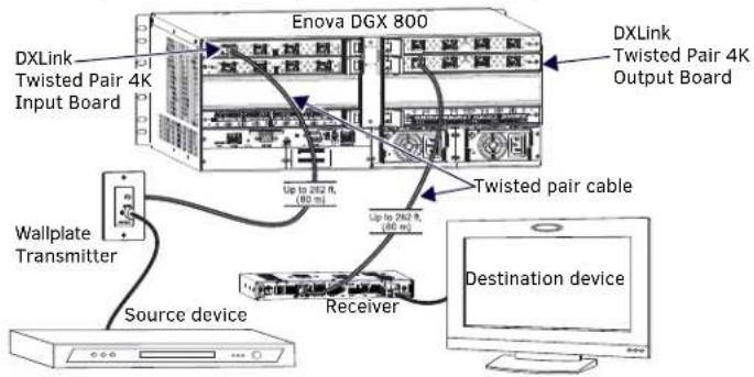
FIG. 1 DXLINK TWISTED PAIR 4K TX AND RX ENDPOINT SOLUTION (CONNECTED TO DGX800-ENC)
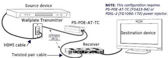
FIG. 2 DXLINK TWISTED PAIR 4K TX AND RX AS EXTENDER SOLUTION
Wallplate Transmitter Mounting
The 4K HDMI Wallplate TX mounts in a standard US single-gang back box. Standard decor style cover plates are customer provided to allow matching the individual decor of an environment or matching other standard decor covers in a room/area.
Receiver Mounting Options (Rack Trays and Mounting Brackets)
For details on the four versatile mounting kit options for V Style modules (rack tray, rack tray with fill plates, surface mount, and pole mount), see www.amx.com
IMPORTANT: When mounting under a surface, the module should be mounted upright and lowered in the mounting bracket slots to provide an airflow gap between the surface and the vent holes. If not using V Style brackets, be sure to leave a gap between the top of the unit and the surface for heat to escape.
Twisted Pair Cable Pinouts and RJ-45 LEDs
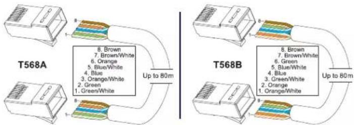
DXLink (for signal transport) and ICS LAN 10/100 (for Private network connection) ports both use twisted pair cable. FIG. 3 shows two pinouts that can be used for either port. FIG. 4 shows the LEDs for each port.
flowchart
graph TD
    subgraph T568A
        A["8. Brown\n7. Brown/White\n6. Orange\n5. Blue/White\n4. Blue\n3. Orange/White\n2. Green\n1. Green/White"] --> B["Up to 80m"]
    end
    subgraph T568B
        C["8. Brown\n7. Brown/White\n6. Green\n5. Blue/White\n4. Blue\n3. Green/White\n2. Orange\n1. Orange/White"] --> D["Up to 80m"]
    end
FIG. 3 RJ-45 PINOUTS
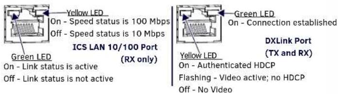
FIG. 4 RJ-45 PORTS
Attaching Signal, Transport, and Control Cables
Important Twisted Pair Cabling Requirements and Recommendations:
- DXLink twisted pair cable runs require shielded category cable (STP) of Cat6A or Cat7.
- DXLink twisted pair cable runs for DXLink equipment shall only be run within a common building.*
- DXLink (RJ-45) connectors must not be used for connecting to a standard Ethernet Network. The connector is used for signal transport.
- D _o_create a network (Ethernet) loop. A network loop is created when the enclosure and one or more of its DXLink Modules are connected to a common Public LAN.
- DXLink delivers 10.2 Gb/s throughput over shielded category cable. Based on this bandwidth requirement, we recommend following industry standard practices designed for 10 Gigabit Ethernet when designing and installing the cable infrastructure.
- The cables should be no longer than necessary to reach the end-points. We recommend terminating the cable to the actual distance required rather than leaving any excess cable in a service loop.
- For complete cable specifications, see the Hardware Reference Manual – DXLink Twisted Pair 4K Transmitters and Receivers.
* "Common building" is defined as: Where the walls of the structure(s) are physically connected and the structure(s) share a single ground reference.
For more details and helpful cabling information, reference the white paper titled
"Cabling for Success with DXLink" available at www.amx.com or contact your AMX representative.
To attach signal and transport cables to the Transmitter:
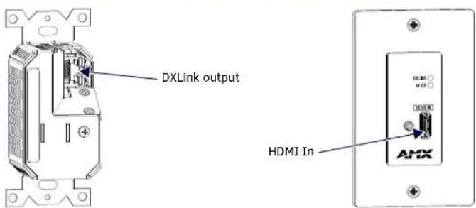
FIG. 5 ATTACH SIGNAL AND TRANSPORT CABLES ON DX-TX-DWP-4K
- DXLink connector – Attach a twisted pair cable to the DXLink output and to a DXLink input connector on the RX (requires PoE injector) or on the switcher.
- Set the Transmitter into single-gang back box. Fasten to back box with screws.
- Place decor style cover plate over Transmitter. Fasten cover plate to Transmitters with screws.
- HDMI In - Attach an HDMI cable from the source to the HDMI In connector.*
* DVI cable can be used via a cable adapter; however, advanced audio support from HDMI will not be available.
To attach signal, transport, and control cables to the Receiver:
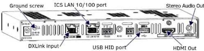
FIG. 6 ATTACH SIGNAL, TRANSPORT, AND CONTROL CABLES ON DXLINK 4K HDMI RECEIVER
-
Set DIP switch toggles if necessary (for settings, see product manual).
-
DXLink input connector - Attach a twisted pair cable from the DXLink output connector on the switcher (or on a TX) to the DXLink input.
-
HDMI Out - Attach HDMI cable from this port to the destination.
-
Stereo Audio Out jack (optional) – Connect an analog audio cable from this port to the destination.
-
Apply power (see below).
Applying Power
A desktop power supply (ENERGY STAR® qualified) is provided with each module. Power can be supplied to DXLink Twisted Pair 4K endpoints by DXLink Power sourcing devices as follows:
• To a Wallplate TX or an RX module from an Enova DGX Switcher or PS-POE-AT-TC (FG423-84) or PDXL-2 (FG1090-170).*
• To an RX module from a Solecis 5x1 4K Multi-Format Digital Switcher (SDX-514M-DX).
* Power Budget: For TXs and/or RXs connected to an Enova DGX, use the Enova DGX Configuration Tool (www.amx.com/enova) to determine power requirements of a configuration and if any DXLink RXs should use local power. The tool contains instructions on how to use it.
Note: Local power takes precedence over DXLink power (via DXLink port) from switcher.
Important: If a desktop power supply is used to power a module, it must be the one provided, which must not be altered in any way. AMX does not support use of any other power supplies or PoE injectors as they may potentially damage the DXLink equipment.
To apply power to a Receiver module:
- Attach the provided clamp-on ferrite bead to the power cord on the AC side of the provided desktop power supply (as close as possible to the power supply, on the cord that attaches to an outlet).
- Plug the cord from the desktop power supply into the power jack on rear of the Receiver (2.1 mm DC Jack for 12 V local power).
- Plug the desktop power supply into an AC external power source. The Power LED on the front of the Receiver illuminates green, indicating a ready state.
Table shows DX-RX-4K LED states on power up. If not normal, check connections.
INDICATOR LED NORMAL POWER UP INDICATES
| Power Green Power is applied | ||
| Digital Video and Audio Green Video and HDMI embedded | audio are present | |
| Scaling: Bypass/Auto/Manual One green, two off Current scaling mode* | ||
| IR TX / IR RX | Red / Yellow | IR activity |
| 232 (Serial) TX / 232 (Serial) RX Red / Yellow Serial activity | ||
| NetLinx Link/Act | Green(Blinking = #3 Toggle OFF) | Active LAN connection to an AMX Network |
| NetLinx Status | Green LAN activity | |
| CEC | OFF | Not currently supported |
| USB | Yellow | Connected to device |
* At power up, the RX defaults to Auto. Press the Scaling button to change the mode.
Table shows DX-TX-DWP-4K LED states on power up. If not normal, check connections.
| INDICATOR LED | NORMAL POWER UP | INDICATES |
| DXLink | Green | Power applied and DXLink connection established |
| HDCP | Solid Green | Transmitting HDCP-encrypted signal |
| Blinking Green Transmitting non-encrypted signal | ||
DXLink Auto-setup with Enova DGX 100 Series Switchers
Auto-setup is the default for using DXLink modules with Enova DGX 100 Series Switchers. For information about Auto-setup, including how to disable Auto-setup, see the Hardware Reference Manual – Enova DGX 100 Series Digital Media Switchers. For information about traditional NetLinx binding (Auto-setup disabled), see the Hardware Reference Manual – DXLink Twisted Pair 4K Transmitters and Receivers.
USB HID Port (Receiver Rear)
This USB HID port on the Receiver supports passing keyboard and mouse USB signals to control a remote computer attached via USB to a DXLink Transmitter with compatible USB HID port (see the Hardware Reference Manual - DXLink Twisted Pair Transmitters/Receiver).
ID Button (Receiver Front)
The ID button can be used to toggle between static and DHCP IP addressing, assign a device address, reset the factory defaults, and restore the factory firmware image (for details, see the Hardware Reference Manual).
Additional Information Covered in Product Manual
For information on the following, see the Hardware Reference Manual – DXLink Twisted Pair 4K Transmitters and Receivers at www.amx.com:
• Supported input and output resolutions
- Pinouts for HDMI cables and DVI-to-HDMI cable adapters
- NetLinx control and programming commands; Telnet commands
- IR file transfers; upgrading firmware image; restoring factory default settings
• RS-232 Serial data, IR control, and USB HID support information
- Compatibility with DXLink Twisted Pair (non-4K) equipment
Reference Documents
- Hardware Reference Manual – DXLink Twisted Pair 4K Transmitters and Receivers
- Hardware Reference Manual – Enova DGX 100 Series Digital Media Switchers
- Hardware Reference Manual – DXLink Twisted Pair Transmitters/Receiver
- Hardware Reference Manual – Solecis Digital Switchers
- White Paper: Cabling for Success with DXLink
- DXLink - HID Supported Devices
- WebConsole & Programming Guide – NX-Series Controllers