
KSR12 - Industribot VELLEMAN - Gratis brugsanvisning og manual
Find enhedens vejledning gratis KSR12 VELLEMAN i PDF-format.

Brugerspørgsmål om KSR12 VELLEMAN
0 spørgsmål om dette apparat. Besvar dem du kender, eller stil dit eget.
Stil et nyt spørgsmål om dette apparat
Download vejledningen til din Industribot i PDF-format gratis! Find din vejledning KSR12 - VELLEMAN og tag din elektroniske enhed tilbage i hånden. På denne side er alle dokumenter nødvendige for brugen af din enhed offentliggjort. KSR12 af mærket VELLEMAN.
BRUGSANVISNING KSR12 VELLEMAN
HYDRAULIC ROBOTARM

natural_image
Black-and-white photo of a robotic arm with visible mechanical joints and wiring (no text or symbols)Assembly & Instruction Manual

Contents
Product Introduction 1
Tools You May Need 1
Mechanical Parts List 2
Plastic Parts 3
Mechanical Assembly
Gripper Unit Assembly 6
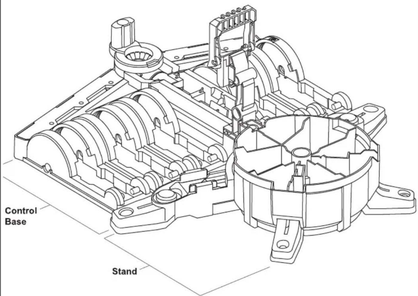
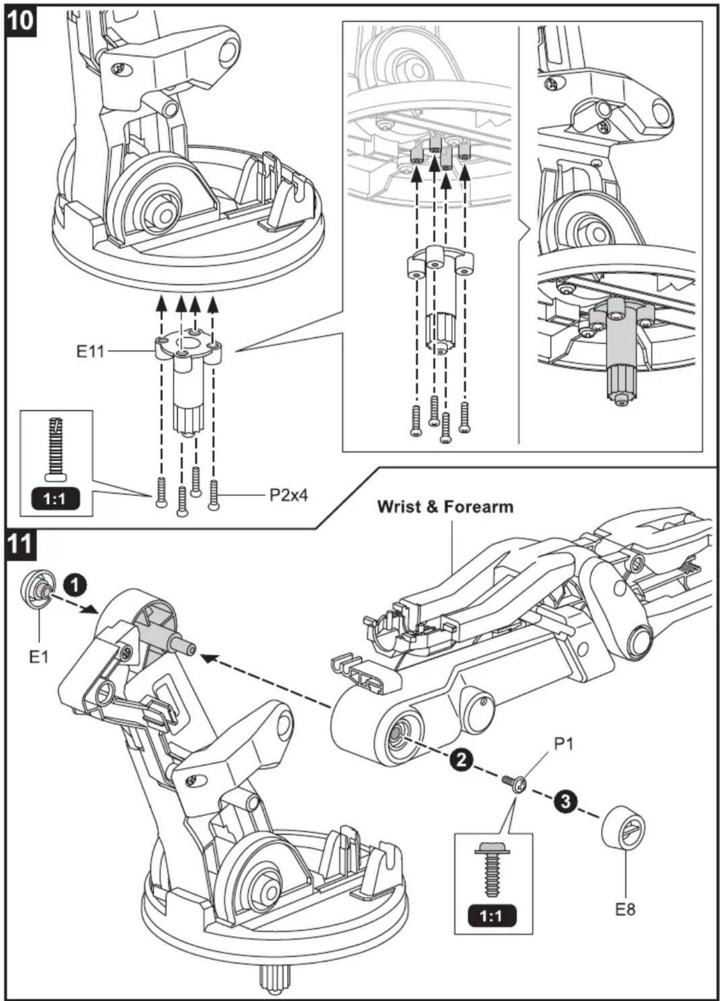
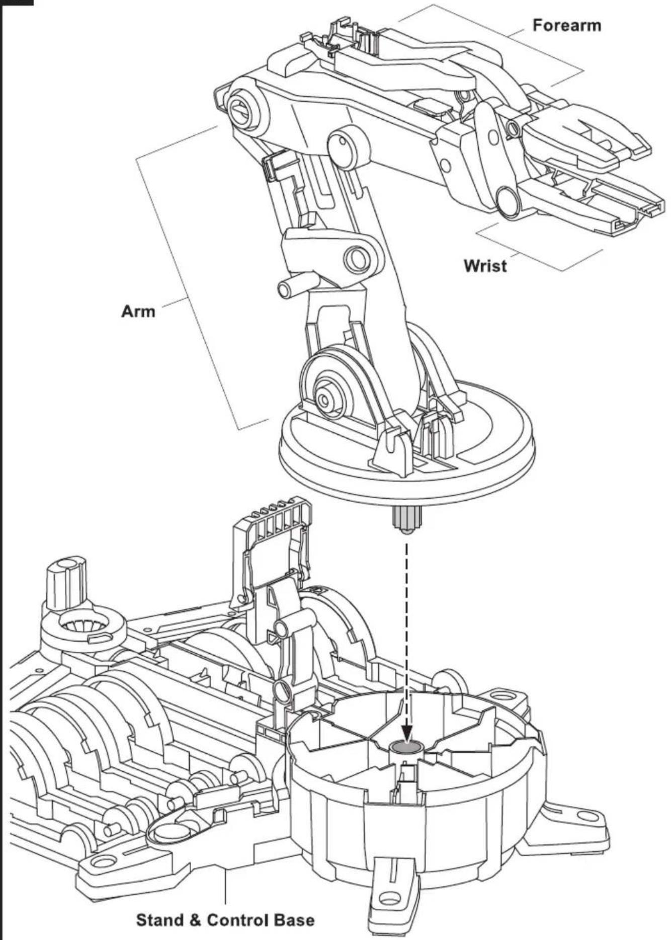
Stand & Control Base Assembly 7
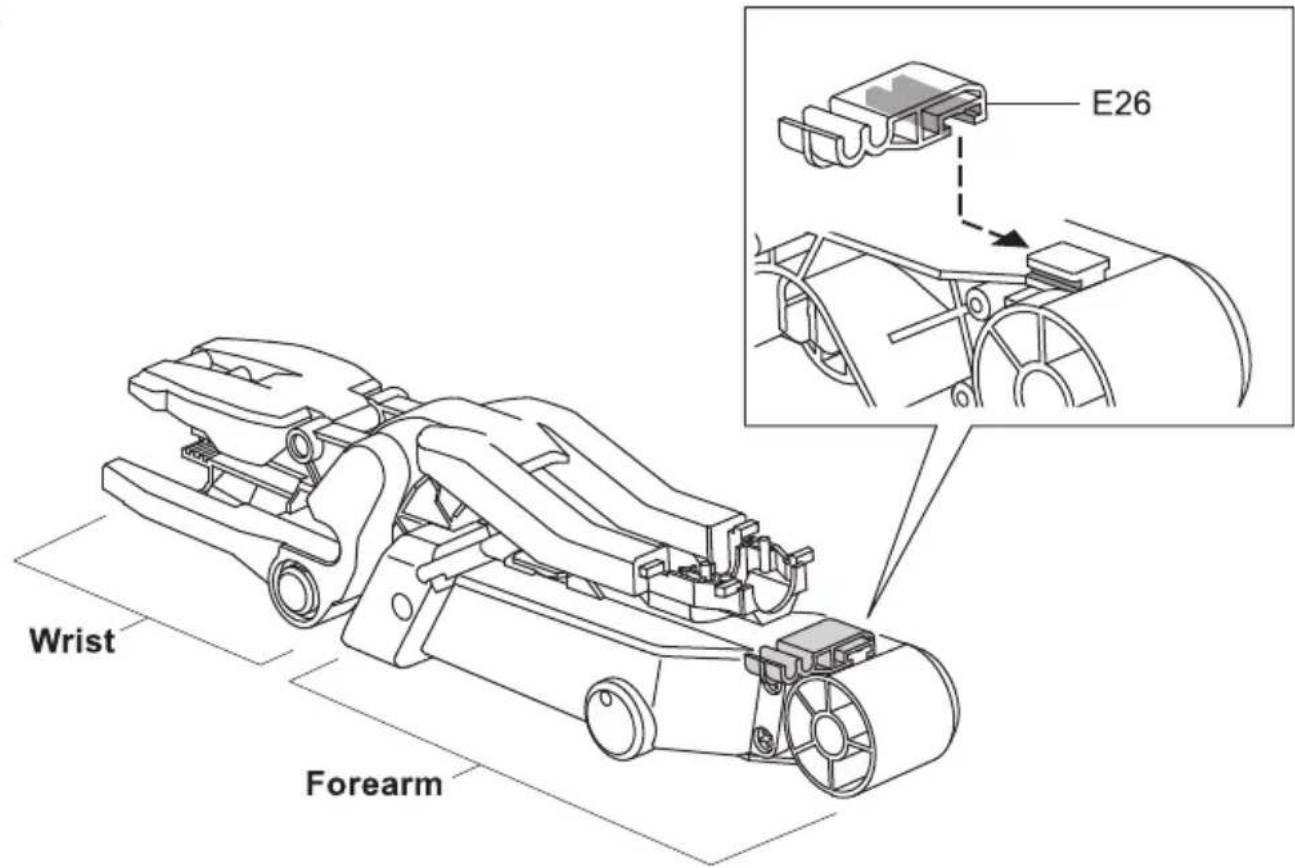
Main Body Assembly 13
How To Oil The Parts 20
H0\~H5 Cylinder Assembly 20
I1 \~ I5 Cylinder Assembly 26
How To Cut The Tube 35
How To Fill Up The Cylinder With Water 36
How To Fit Tube 37
Hydraulic Cylinder Module Assembly 37
Lever Controller Assembly 49
Controller Module Assembly 51
Robot Arm Module Assembly 66
How To Play 76
Trouble Shooting 86
HYDRAULICROBOTARM
Product Introduction
This Robot Arm has made a little more interesting and hydro-mechanically fun.
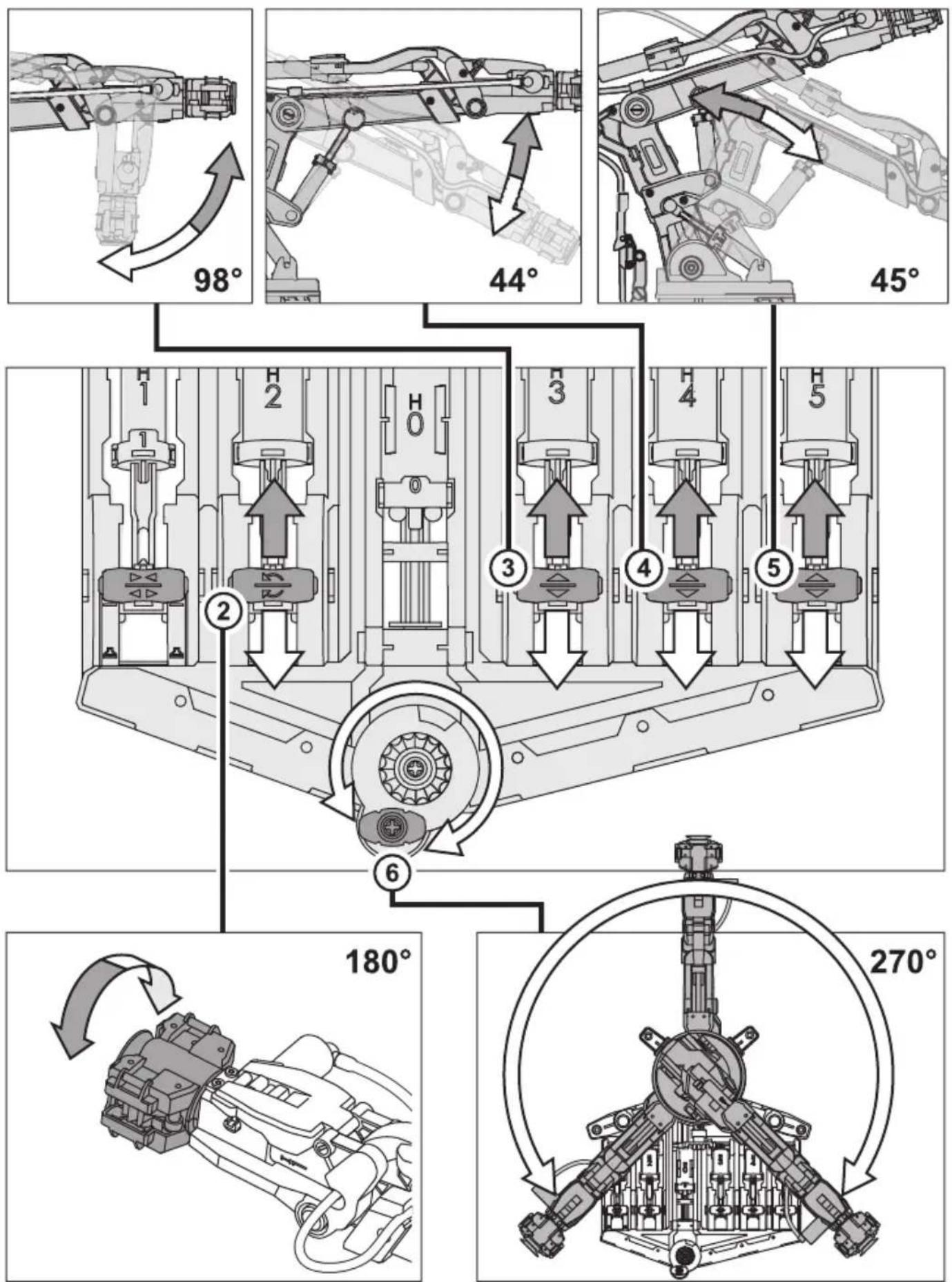
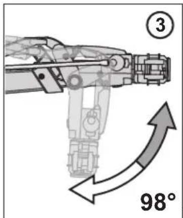
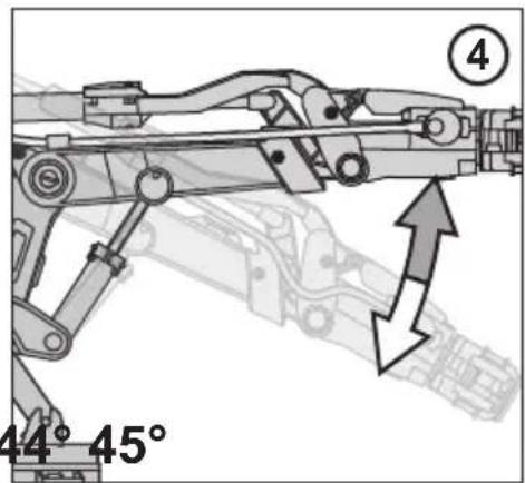
With Hydraulic Arm Edge, command six axes of varied movements: the gripper to open and close up to 1.89 inches, wrist rotation of 180 degrees, wrist mobility of 98 degrees, elbow range of 44 degrees, base rotation of 270 degrees, and shoulder motion of 45 degrees. With a vertical reach of 16.35 inches, horizontal reach of 12.42 inches, and lifting capacity of 50g, your robotic friend is ready for your genius to erupt. With the removal of the gripper, you can activate the suction apparatus. This feature enables the user to elevate objects with a larger surface area (like a small mobile phone). Another prodigious attribution is a braking system that is integrated in the lever controllers to execute all commands accurately. WOW!
How does Hydraulic Robot Arm equate to fun? Children will have total command and visual manipulation using the science principles of a Hydraulic system and its application. Easy to follow instructions with detailed graphic illustrations pave the way for successful and satisfying kit building of 229 pieces. Compliment your engineering, math, science, and technology learning strategy. No battery or motor required. It is powered by water; thus, the "Hydraulic" significance and how it manipulates axes movement via lever controllers. Hydraulic Robot Arm is recommended for ages 10 and up, but with its 229 assembly parts, it will challenge the beginner engineering enthusiasts.
Tools You May Need
Diagonal Cutter
natural_image
Illustration of a screwdriver with a plus sign pointing to its tip (no text or symbols present)Screwdriver
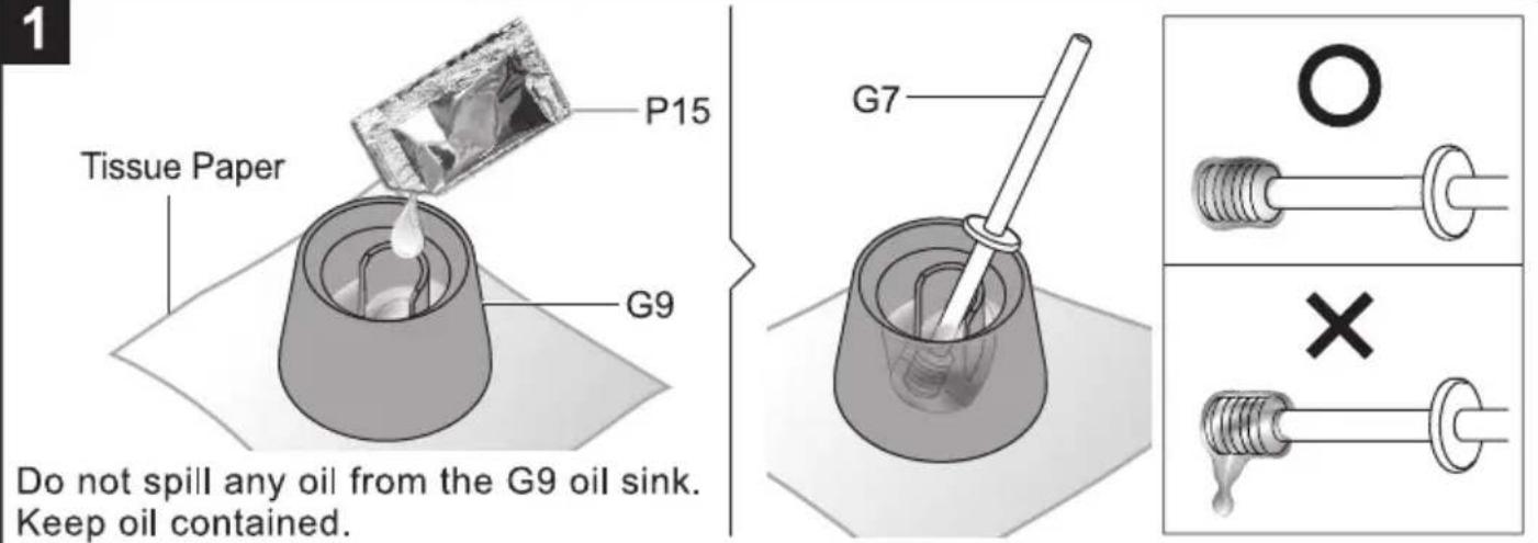
Scissors
Tissue Paper
Cup & Water
Marker Pen (Fine)
or

Tape Measure or Ruler
Mechanical Parts List

Product contains functional edges and sharp points.
P1
Tapping Screw(Short)
9 pcs
P3
Iron Bar (Short)
natural_image
Simple 3D rectangular block illustration with no text or symbols1 pc
P2
Tapping Screw(Long)
28 pcs
P4
Iron Bar (Long)
natural_image
Simple 3D rectangular block with no text or symbols1 pc
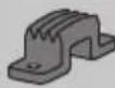
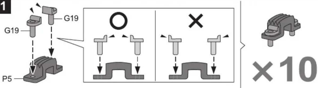
P5
Brake Pad
10 pcs
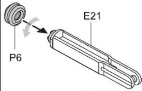
P6
Cap (Small)

5 pcs
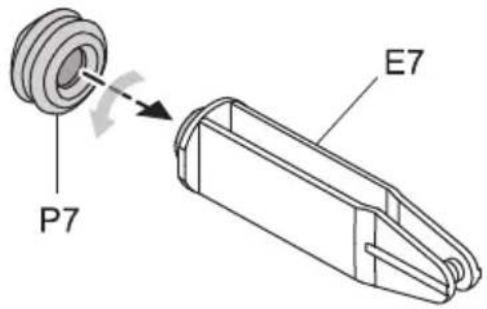
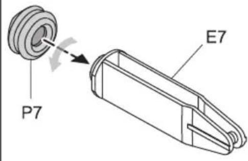
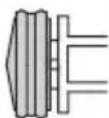
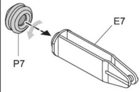
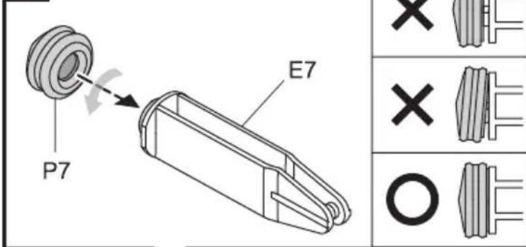
P7
Cap (Big)
6 pcs
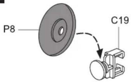
P8
Suction Cup
natural_image
3D rendering of a circular mechanical component with concentric rings (no text or symbols)1 pc
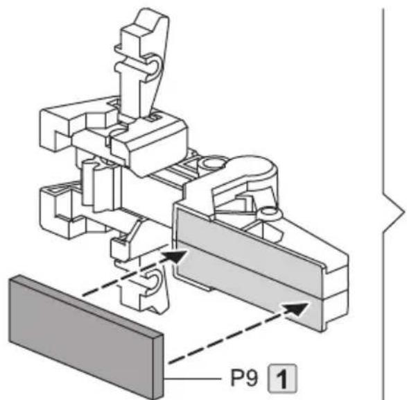
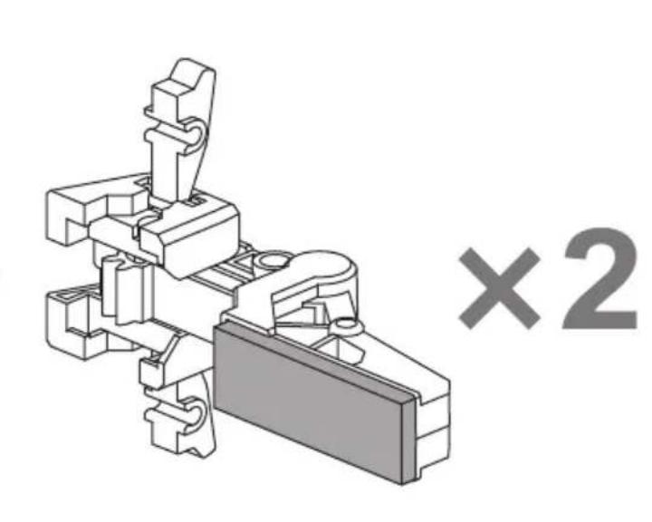
P9
Sponge
1 pc
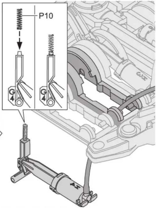
P10
Spring(Smallest)

5 pcs
P11
Spring(Short)
1 pc
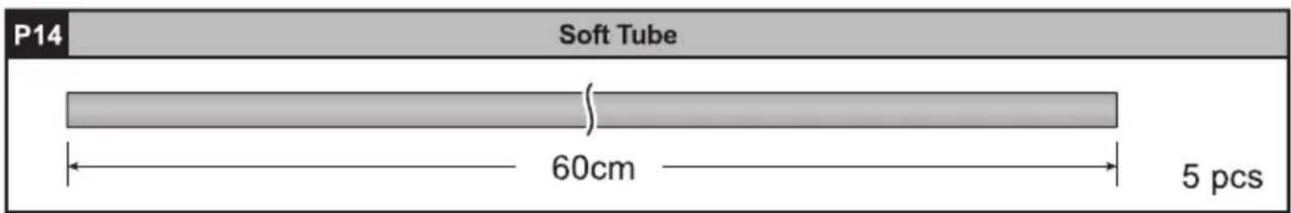
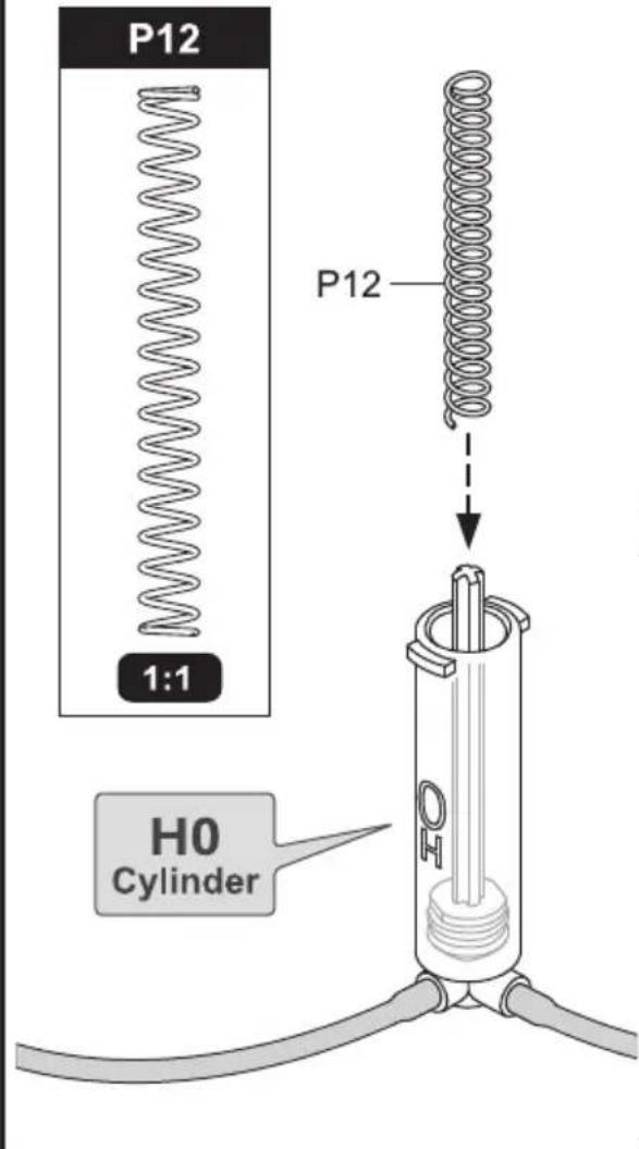
P12
Spring(Medium)
1 pc
P13
Spring(Long)
natural_image
Pure electrical circuit lines without any symbols1 pc
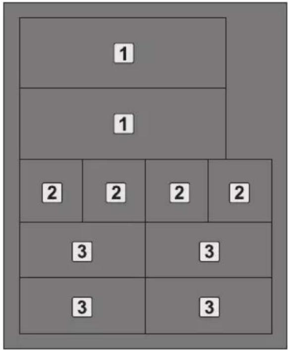
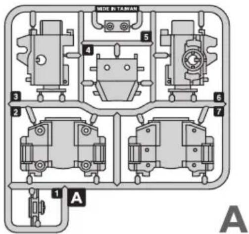
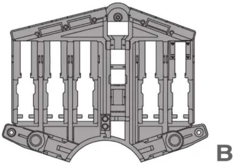
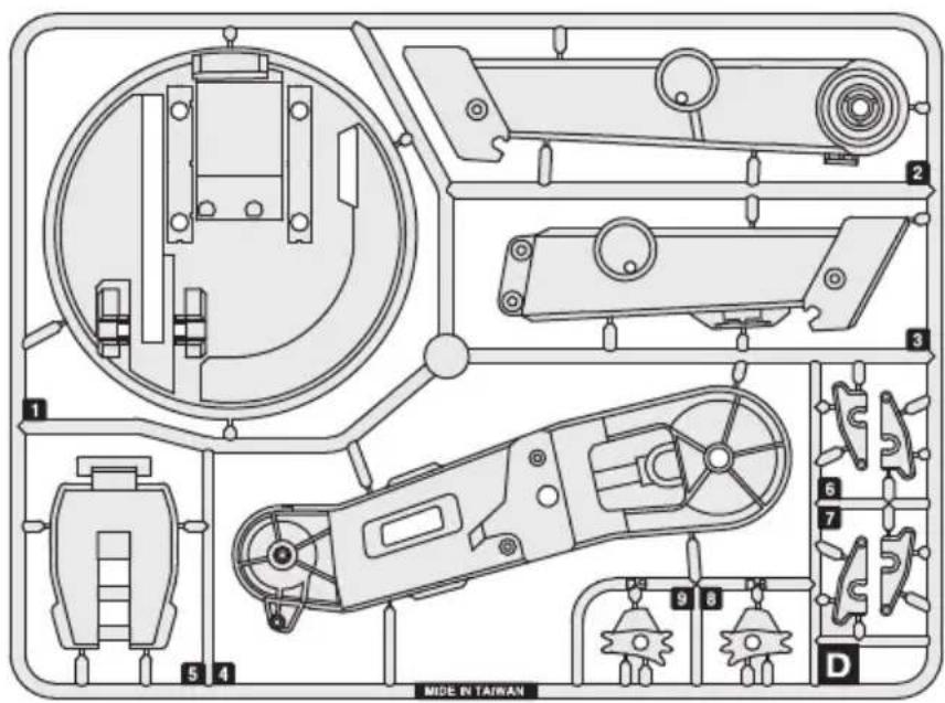
Plastic Parts

Cut the plastic parts when they are required. Do not cut them in advance.
natural_image
Technical line drawing of a mechanical assembly frame with no visible text or symbols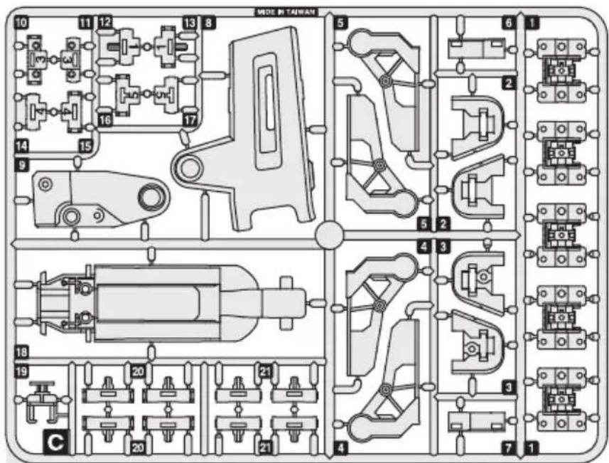

D
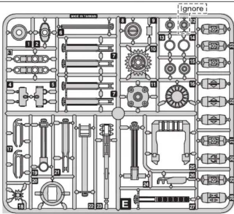
E
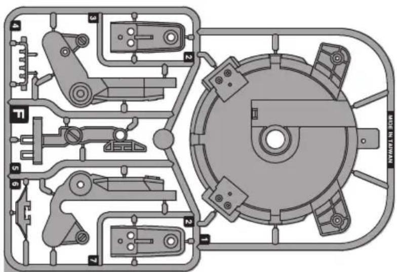
F
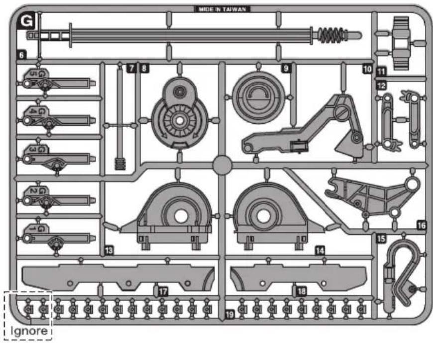
G
H
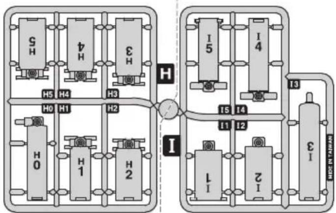
flowchart
graph TD
    subgraph System_1
        A["SH"] --> B["H0"]
        C["H4"] --> D["H1"]
        E["H3"] --> F["H2"]
        G["S"] --> H["H5"]
    end
    subgraph System_2
        I["I"] --> J["1"]
        K["I"] --> L["2"]
        M["I"] --> N["3"]
        O["I"] --> P["4"]
        Q["I"] --> R["5"]
        S["I"] --> T["6"]
        U["I"] --> V["7"]
        W["I"] --> X["8"]
        Y["I"] --> Z["9"]
        AA["I"] --> AB["10"]
        AC["I"] --> AD["11"]
        AE["I"] --> AF["12"]
        AG["I"] --> AH["13"]
    end
    subgraph System_3
        AI["I"] --> AJ["15"]
        AK["I"] --> AL["14"]
        AM["I"] --> AN["13"]
    end
    subgraph Control Valve
        AO["I"] --> AP["15"]
        AQ["I"] --> AR["14"]
        AS["I"] --> AT["13"]
    end
    style System_1 fill:#f9f,stroke:#333
    style System_2 fill:#f9f,stroke:#333
    style Control Valve fill:#ccf,stroke:#333
I
!
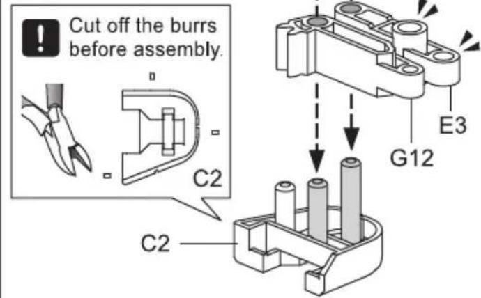
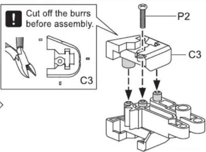
Tip: cut off the burrs before assembly
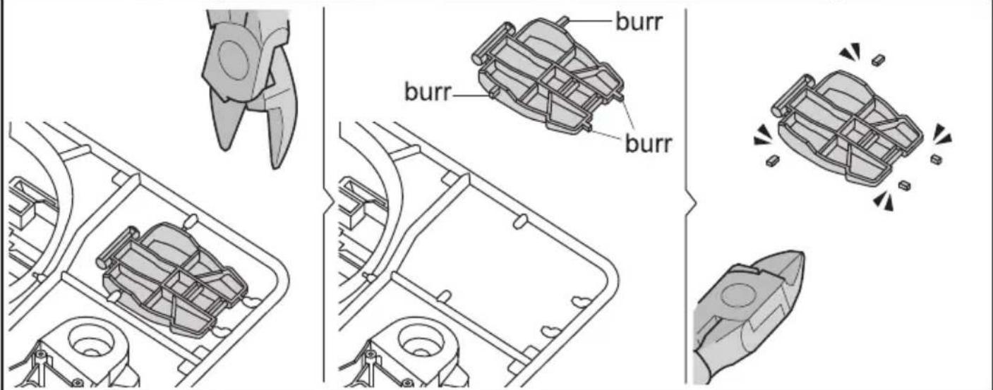
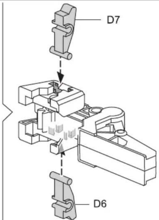
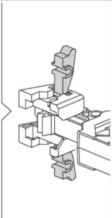
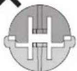
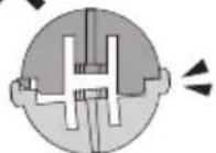
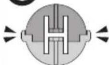
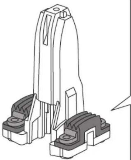
Gripper Unit Assembly
1
2
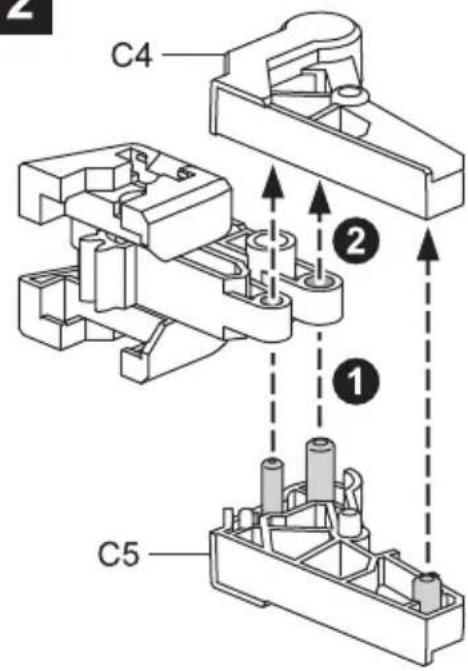
natural_image
Technical line drawing of a mechanical assembly with no visible text or symbols3
natural_image
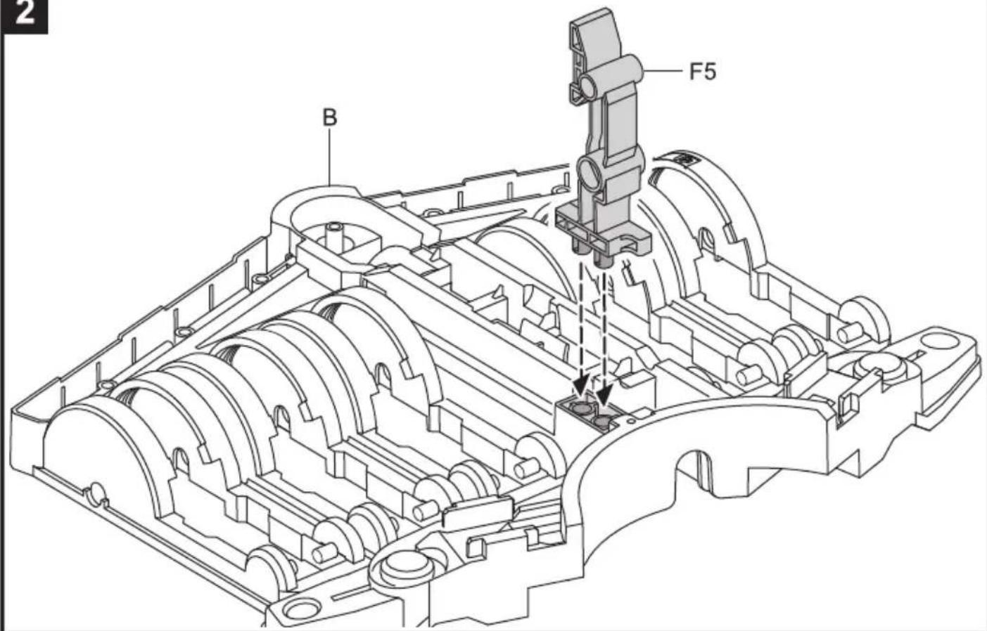
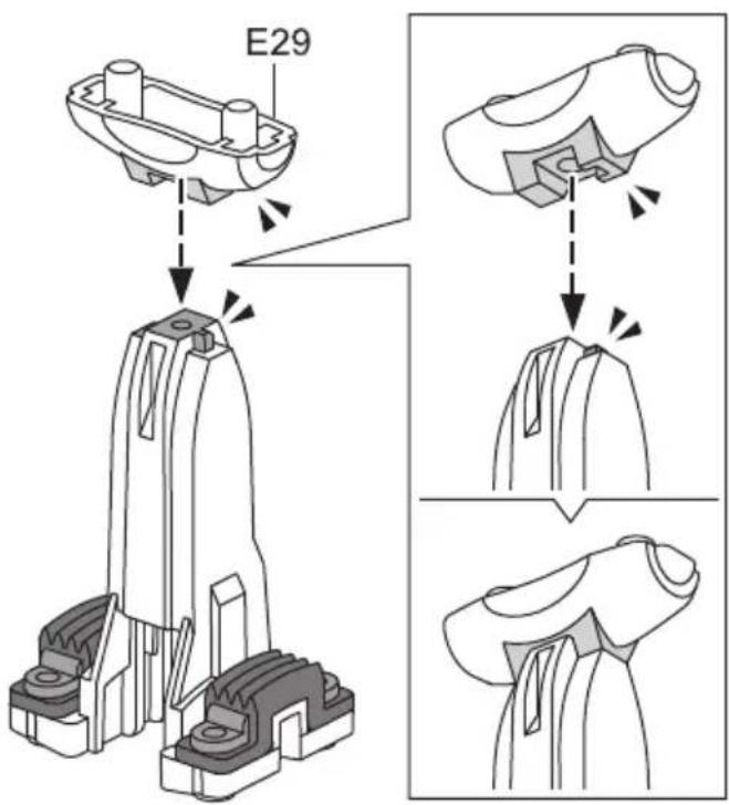
Mechanical component diagram with no visible text or symbolsStand & Control Base Assembly
1

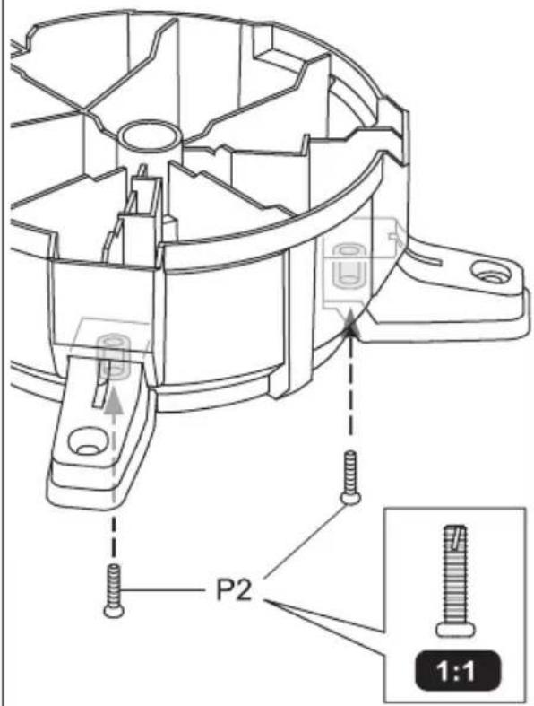
2
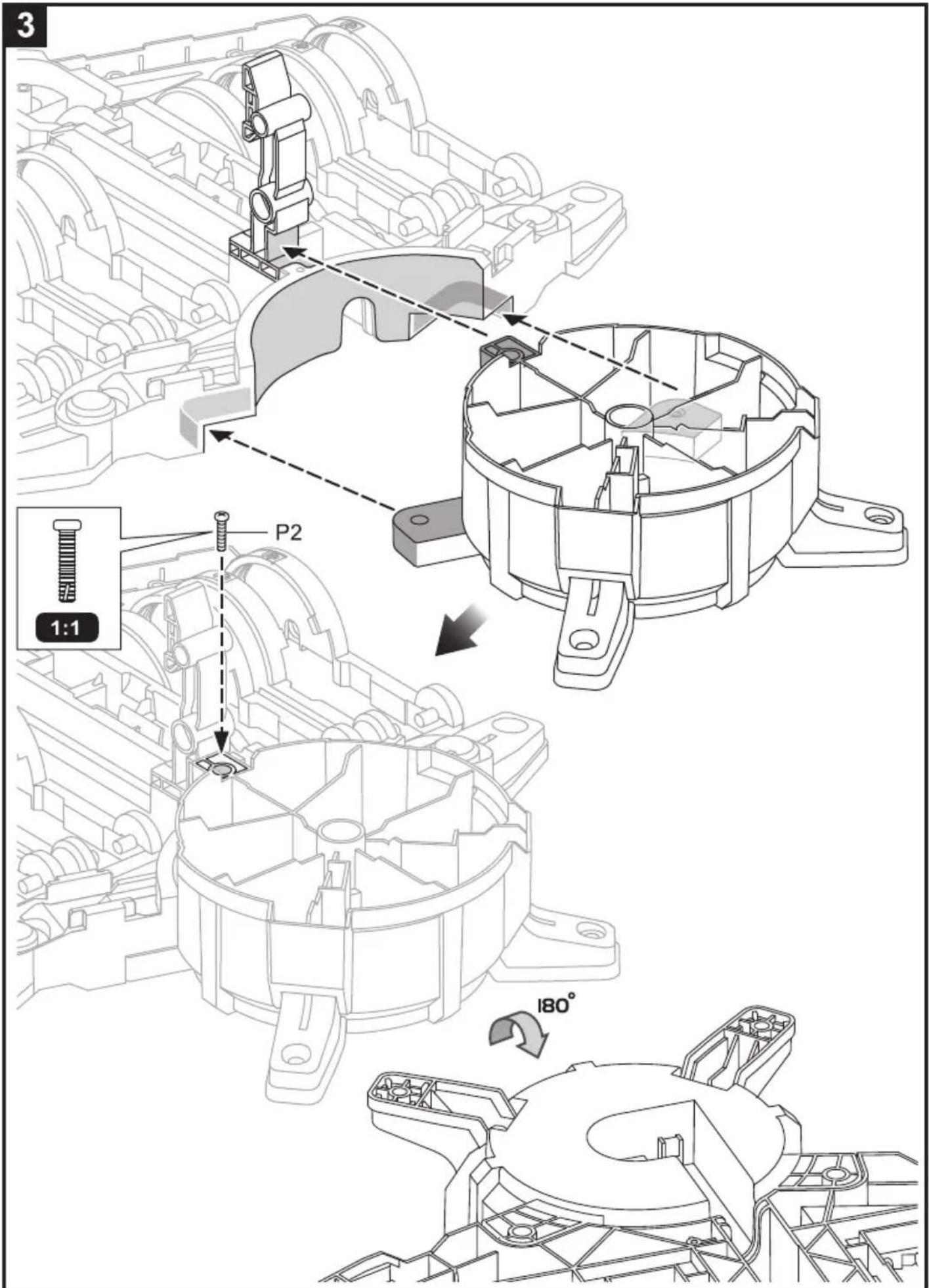
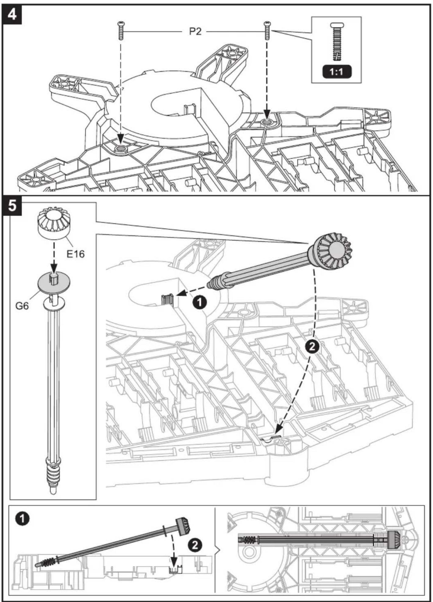
10
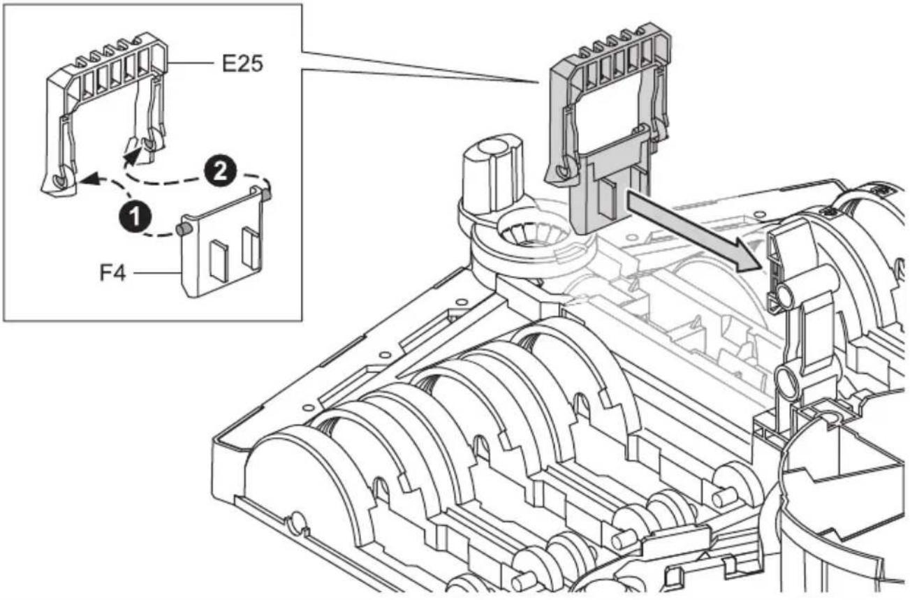
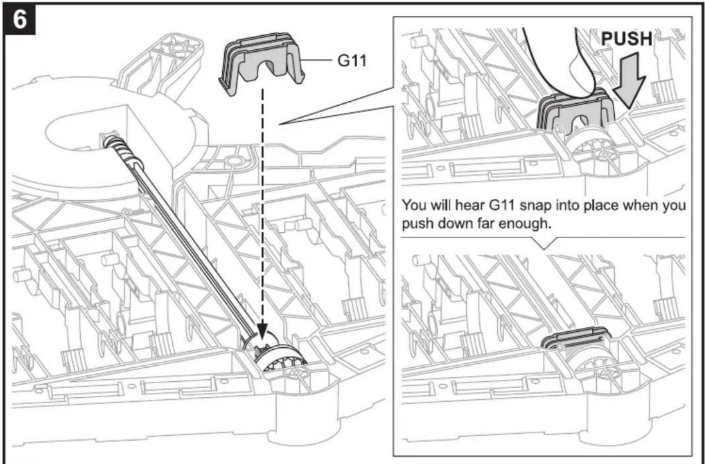
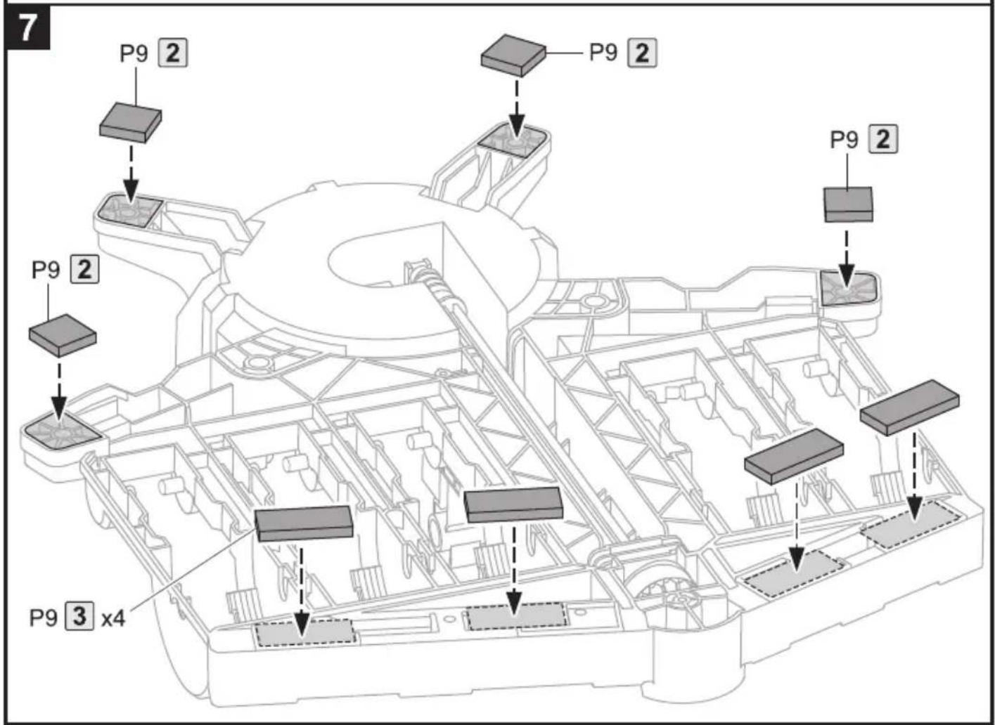
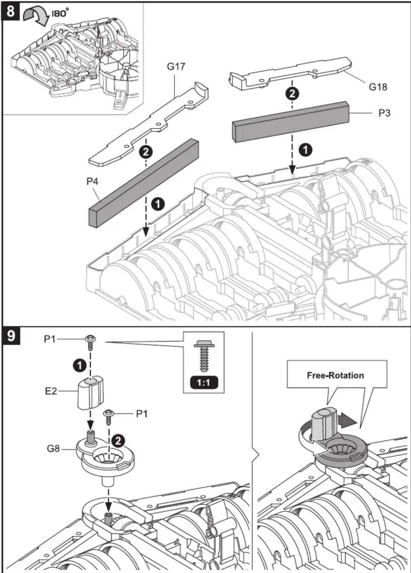
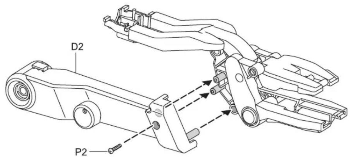
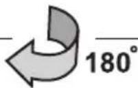
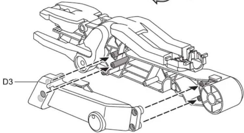
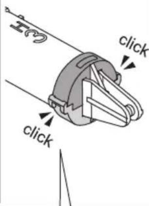
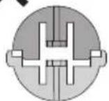
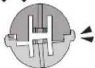
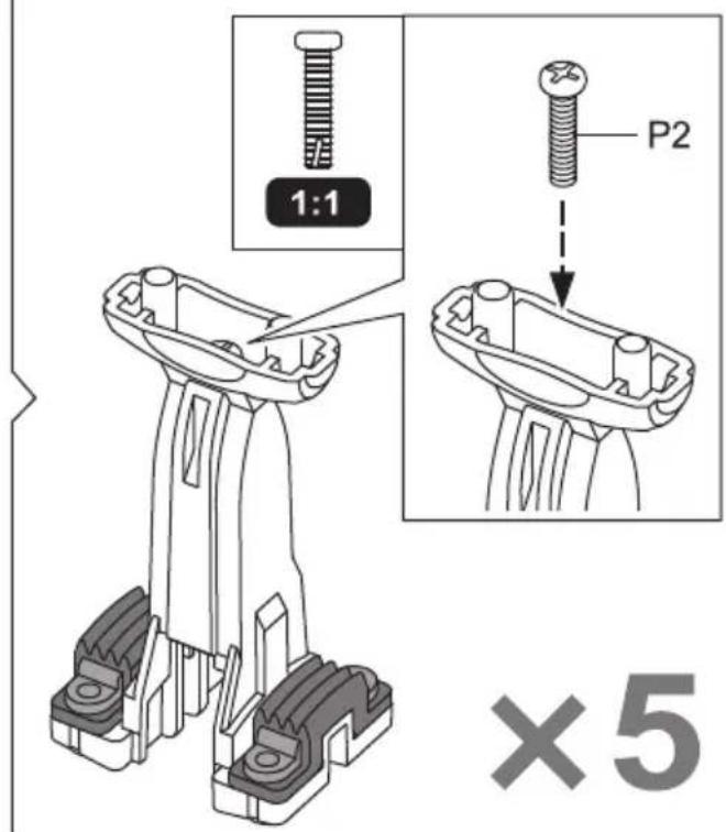
Main Body Assembly
1
2
3
4
5
6
7
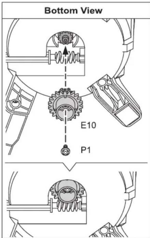
12
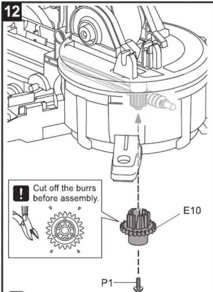
! Make sure E10 is not inserted upside down.
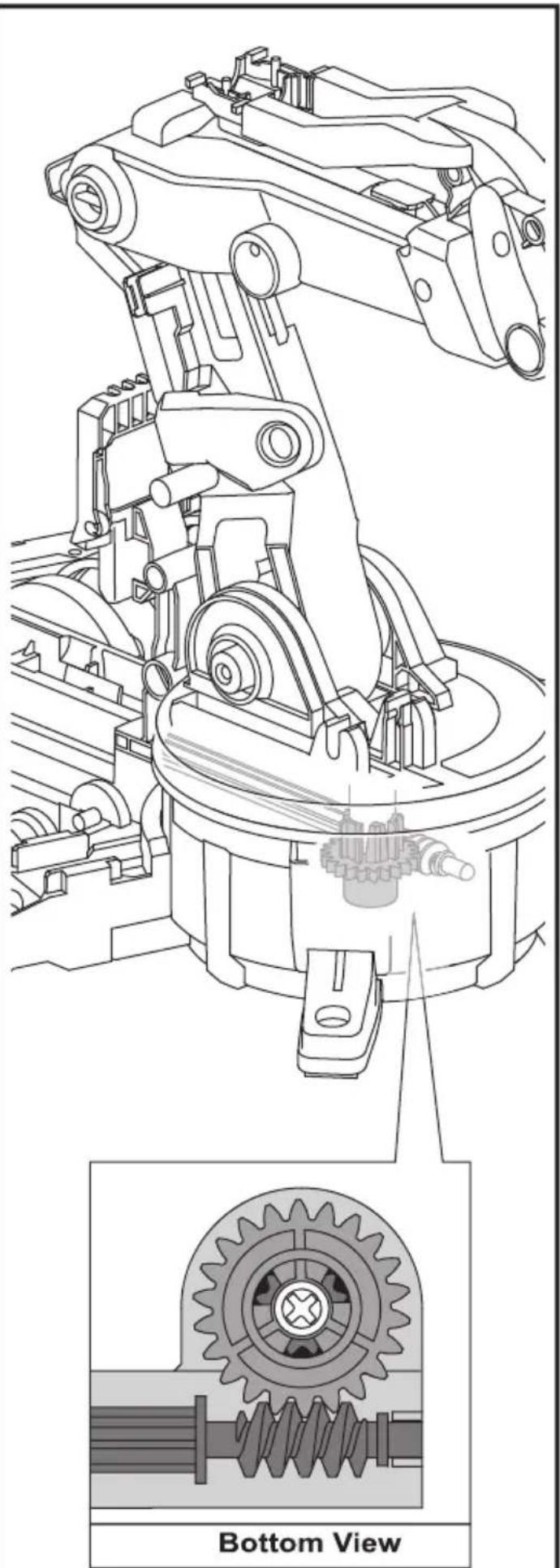
natural_image
Technical line drawing of a mechanical assembly with gear and shaft components, showing top and bottom views (no text or symbols)How To Oil The Parts
2

= Apply Oil
Note : Oil the parts when

appears.

Do not oil outside the shadow as shown below.
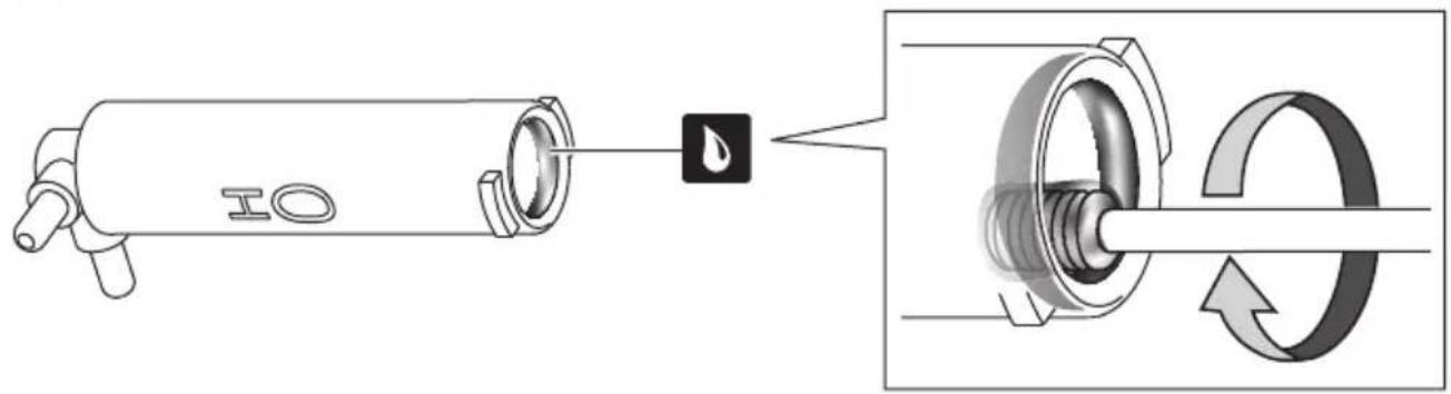
H0\~H5 Cylinder Assembly
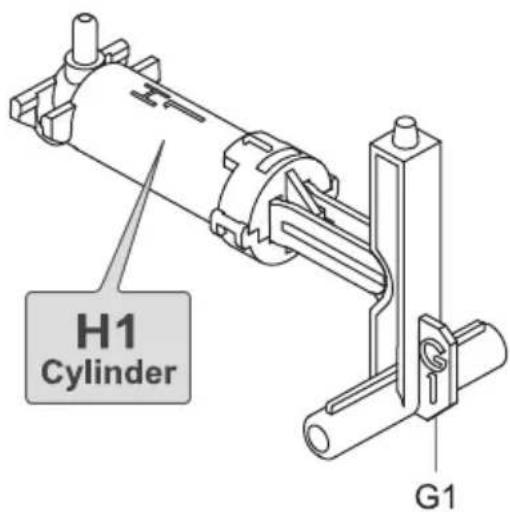
H0 Cylinder Assembly

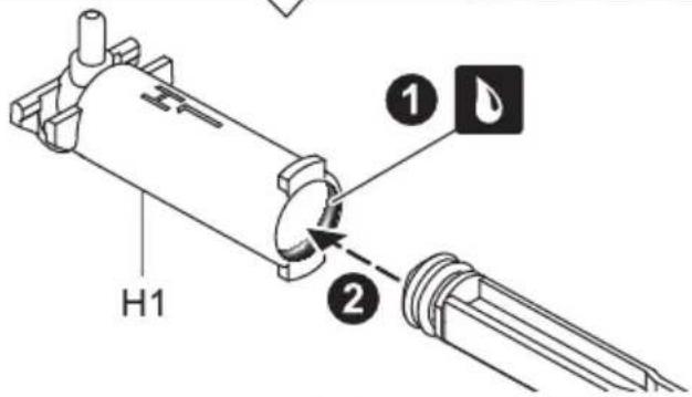
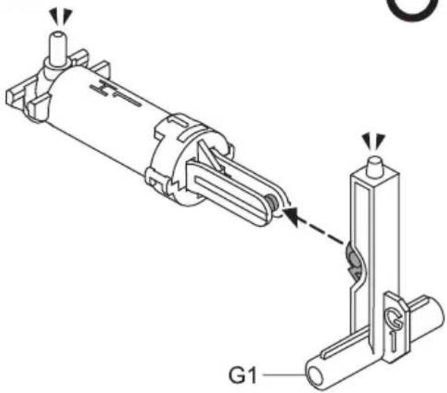
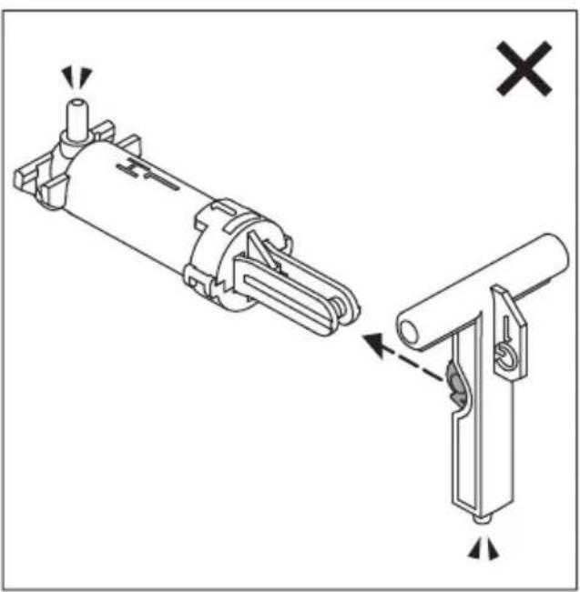
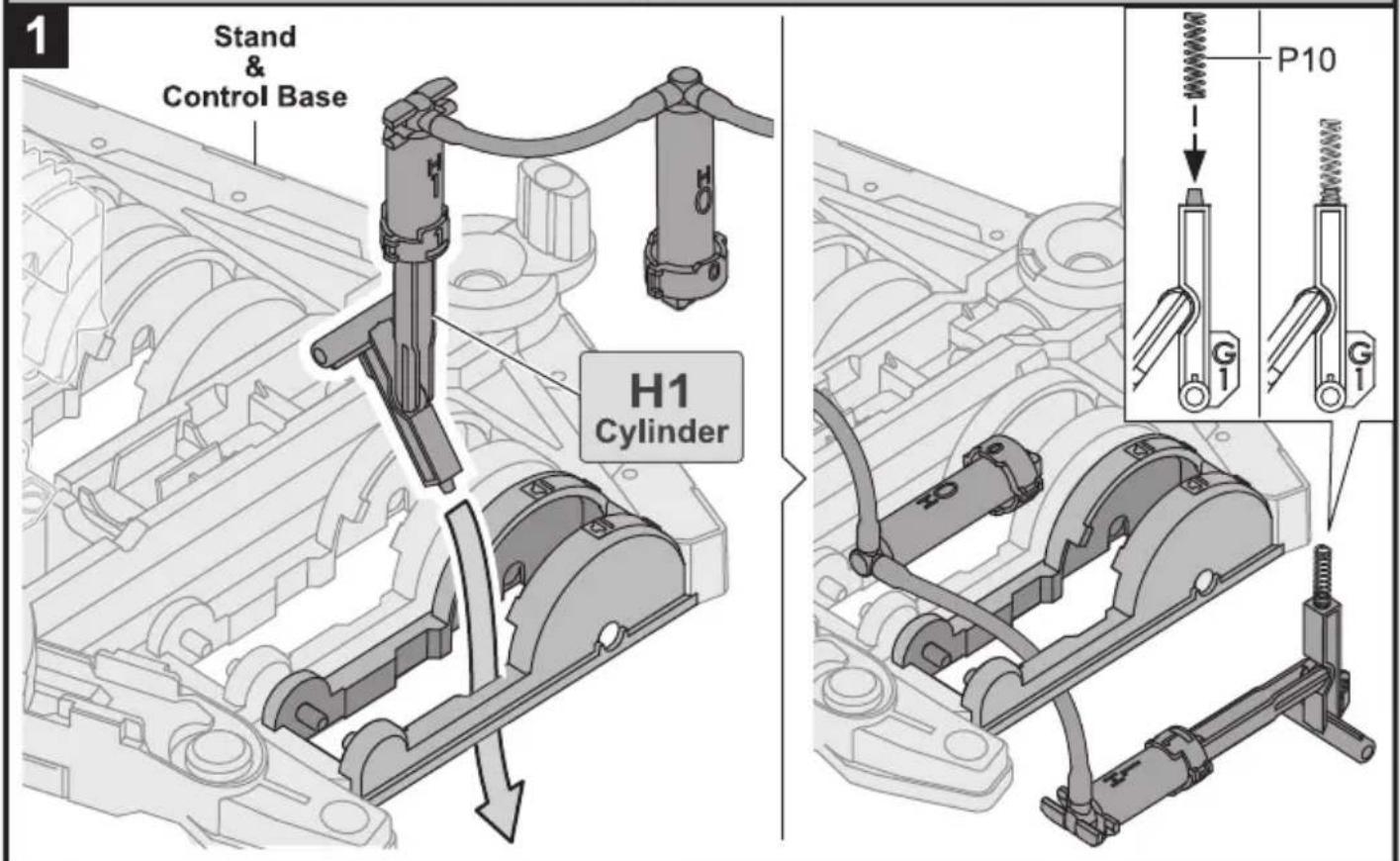
H1 Cylinder Assembly
1


natural_image
Technical illustration of a mechanical component with cross-sectional view (no text or symbols)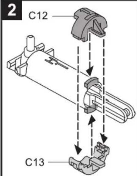
O
natural_image
Pure electrical circuit lines without any symbols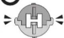
3
natural_image
Technical diagram showing mechanical assembly with no visible text or symbols4
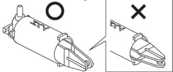
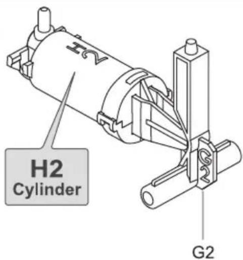
H2 Cylinder Assembly
1


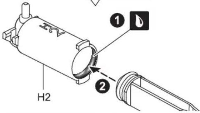
natural_image
Technical illustration of a mechanical component with cross and circle annotations (no readable text or symbols)2
×
×
O
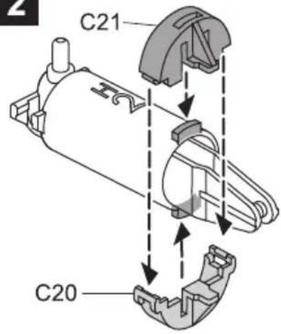
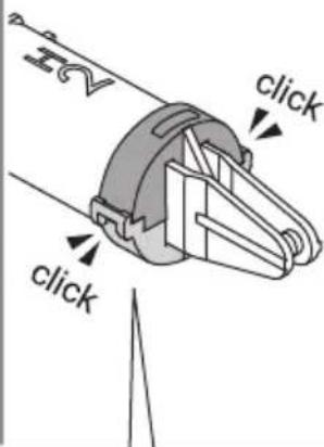
3
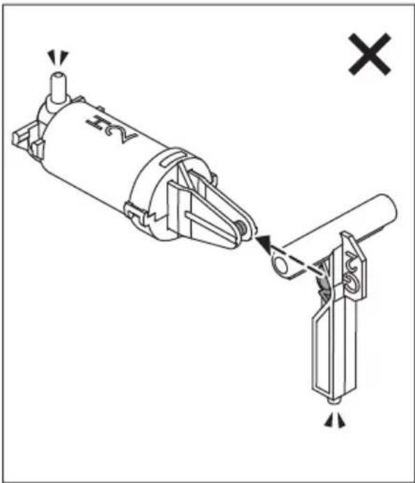
natural_image
Mechanical assembly diagram showing a cylindrical component being lifted by a lever, with no visible text or symbols.4
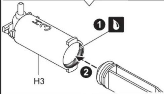
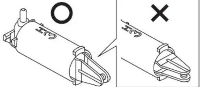
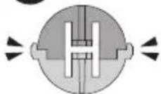
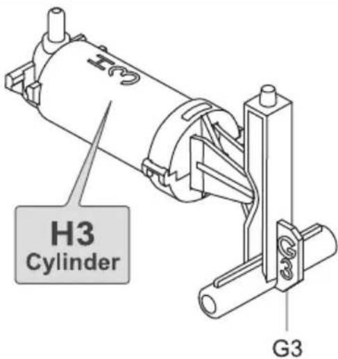
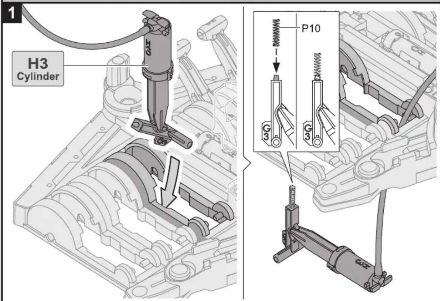
H3 Cylinder Assembly
1


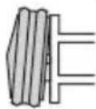

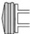
natural_image
Technical illustration of a mechanical component with cross and circle symbols (no text or labels)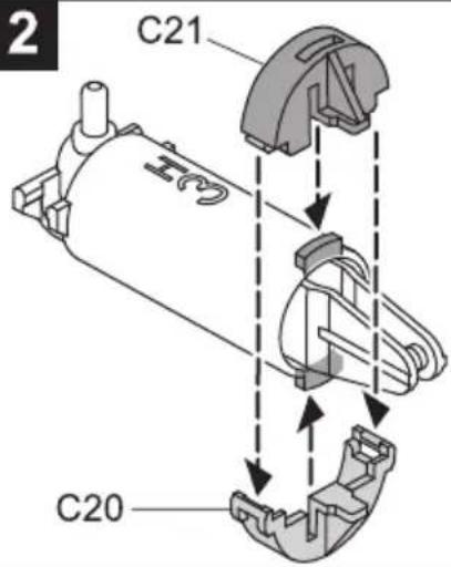
×
×
O
3
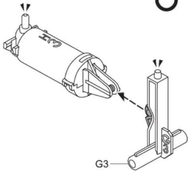
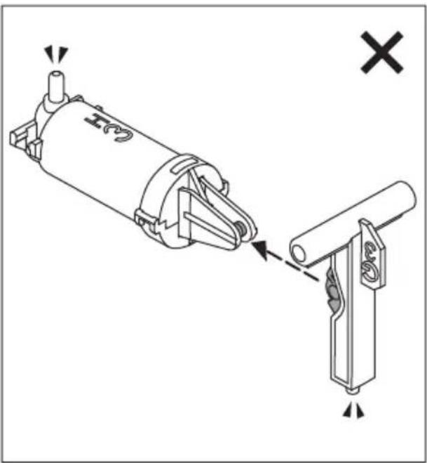
natural_image
Technical diagram of a mechanical assembly with two components, one showing a pin and the other a bracket (no text or symbols present)4
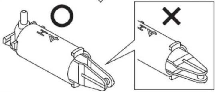
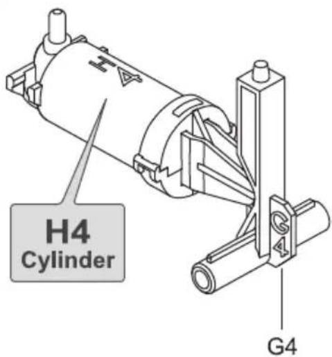
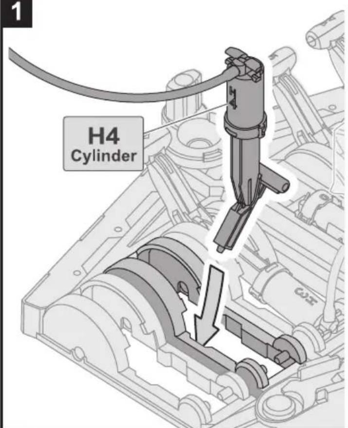
H4 Cylinder Assembly
1


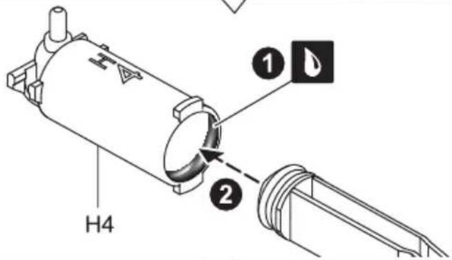
natural_image
Technical illustration of a mechanical component with crosshair symbol (no text or labels)2
×
×
O
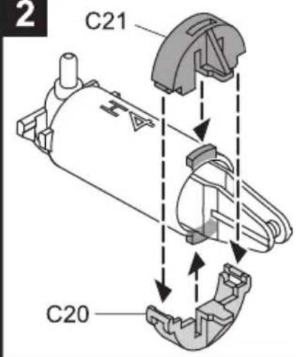
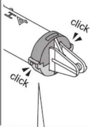
3
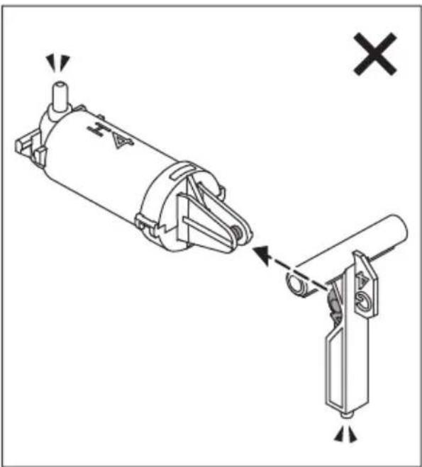
natural_image
Technical diagram of a mechanical assembly showing a cylindrical component being inserted into a bracket, with no visible text or symbols.4
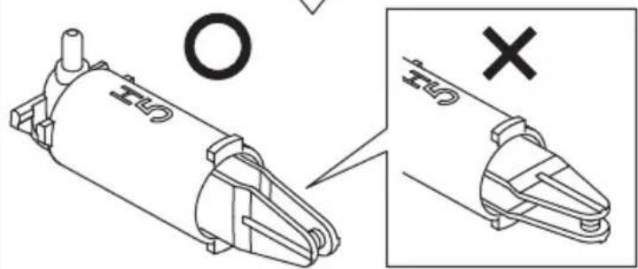
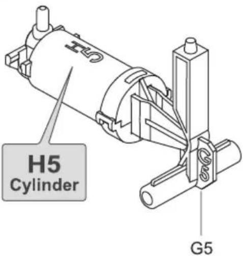
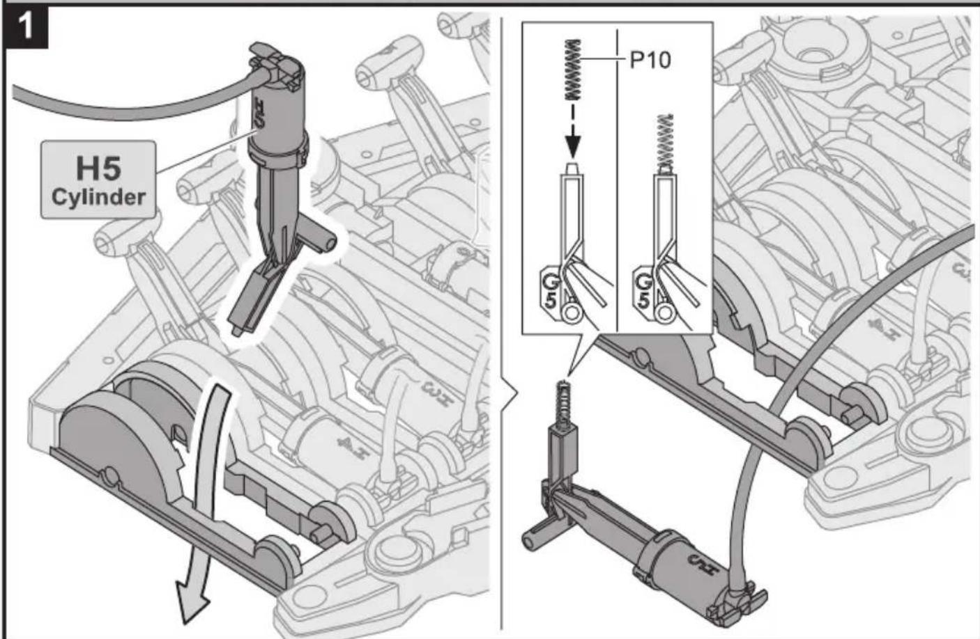
H5 Cylinder Assembly
1


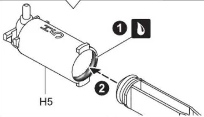
natural_image
Technical illustration of a mechanical component with crosshair and magnified detail view (no text or symbols)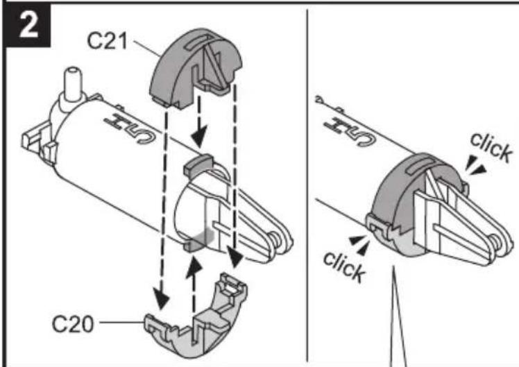
×
×
O
3
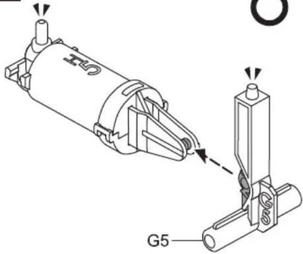
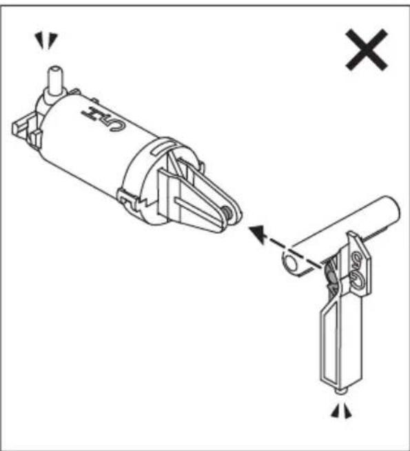
natural_image
Technical diagram showing a mechanical assembly with two views: one with a cylindrical component and the other with a vertical rod (no text or symbols present)4
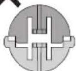
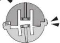
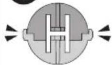
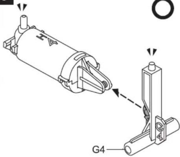
I1 \~ I5 Cylinder Assembly
I1 & I2 Cylinder
1
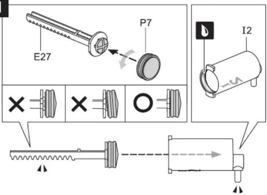
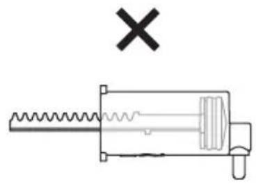
natural_image
Pure mechanical diagram of a spring-loaded tool with no text or symbols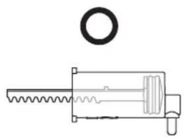
natural_image
Technical line drawing of a mechanical assembly with a circular component and threaded shaft (no text or symbols)2
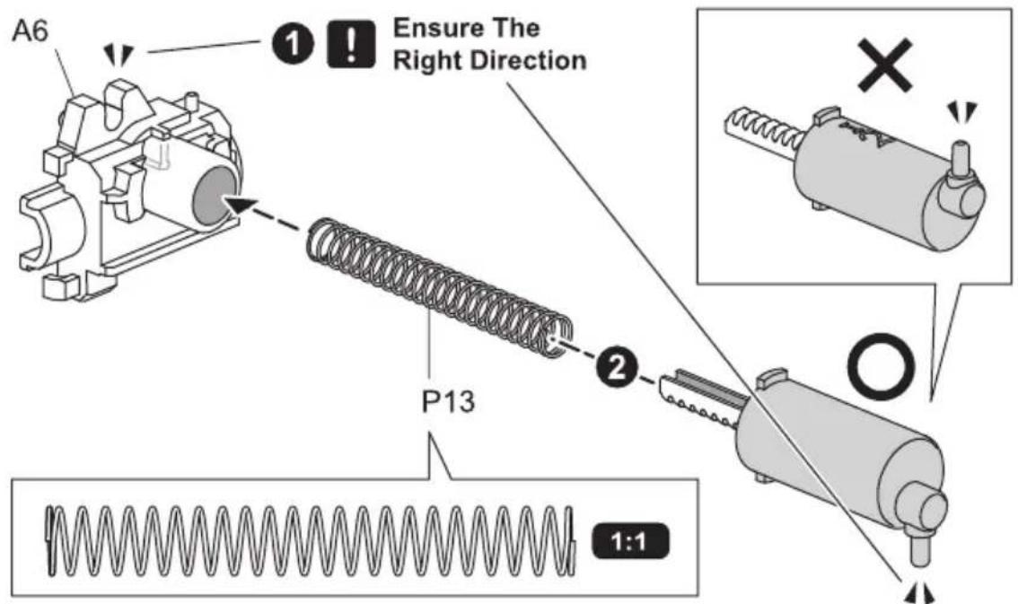
3
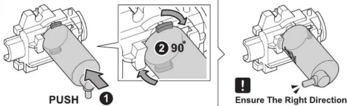
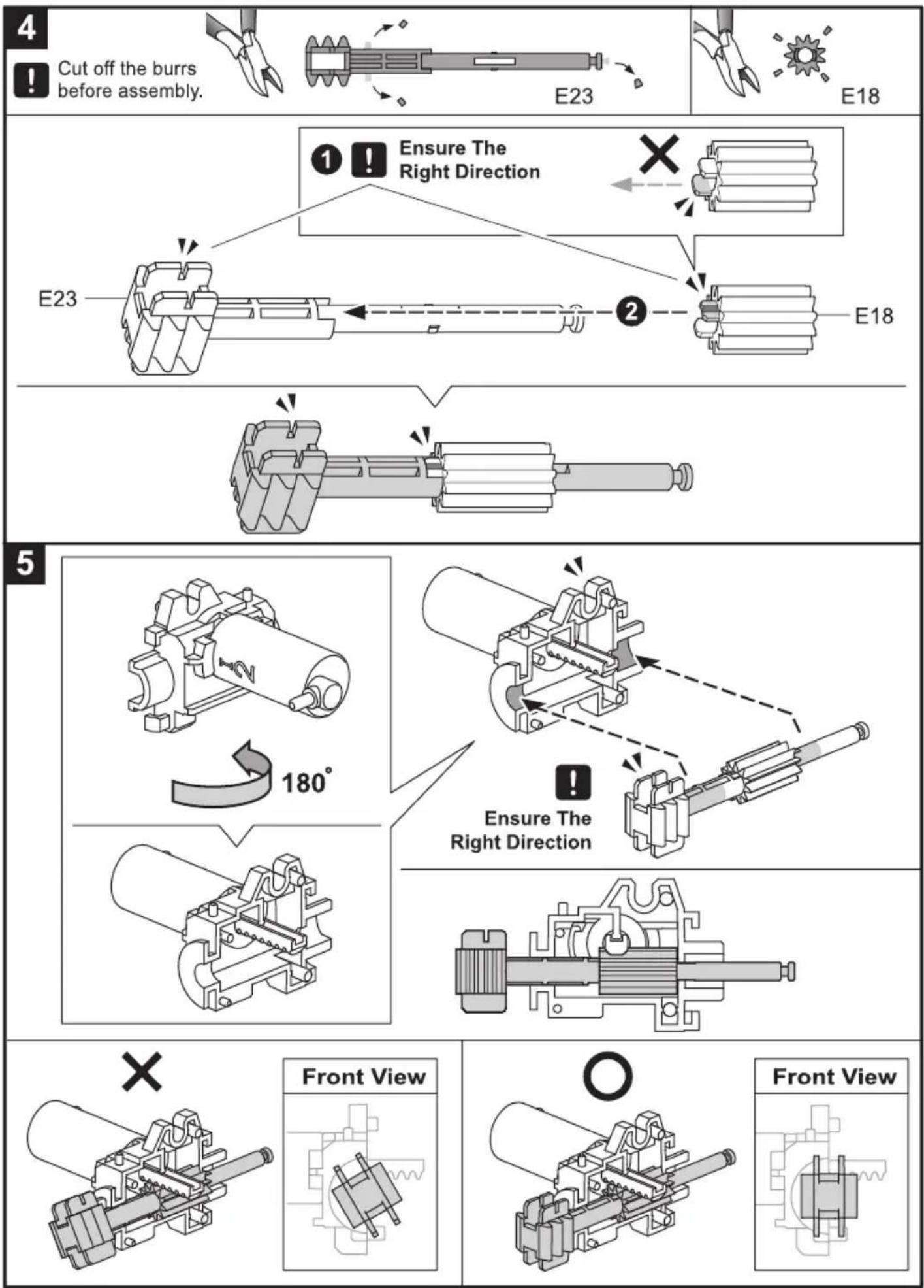
flowchart
graph TD
    A["Cut off the burrs before assembly."] --> B["E23"]
    B --> C["E18"]
    D["Ensure The Right Direction"] --> E["E23"]
    E --> F["E18"]
    G["180°"] --> H["End"]
    I["Ensure The Right Direction"] --> J["End"]
    K["Front View"] --> L["Front View"]
11
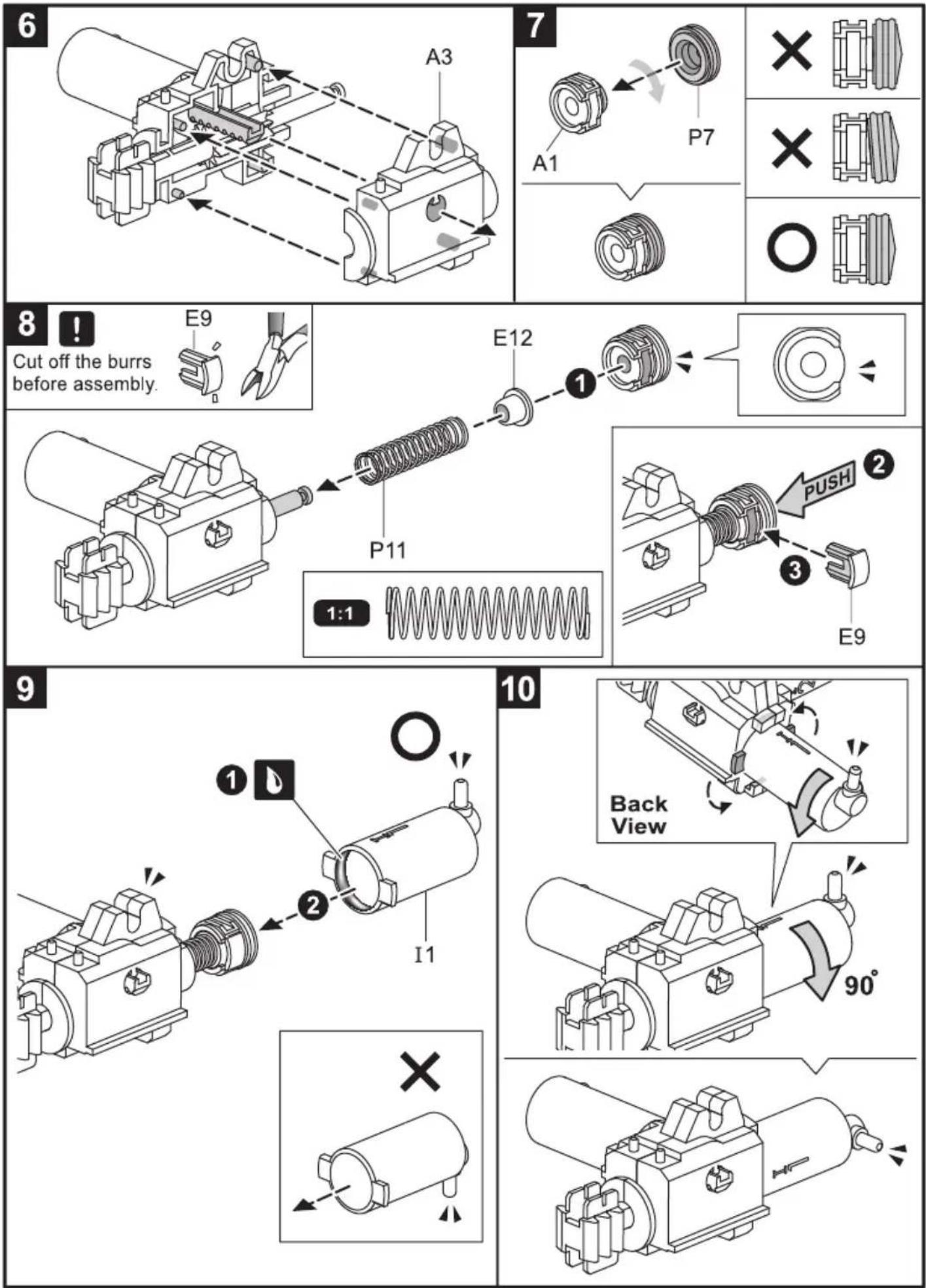
natural_image
Technical line drawing of a mechanical device with no visible text or symbols
×
natural_image
Technical line drawing of a mechanical assembly (no text or symbols)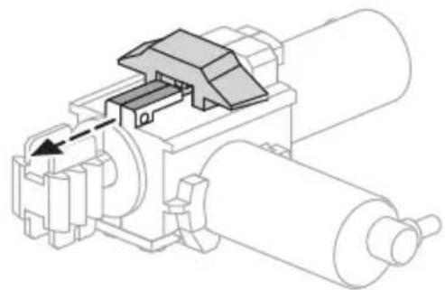
natural_image
Technical line drawing of a mechanical assembly with rollers and a valve (no text or symbols)O
natural_image
Technical line drawing of a mechanical assembly (no text or symbols)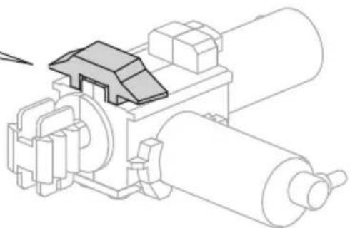
natural_image
Technical line drawing of a mechanical assembly with rollers and a housing (no text or symbols)12
13

14
1
natural_image
Pure mechanical assembly diagram without any text, numbers, or symbols2
natural_image
Pure mechanical assembly diagram without any text, numbers, or symbols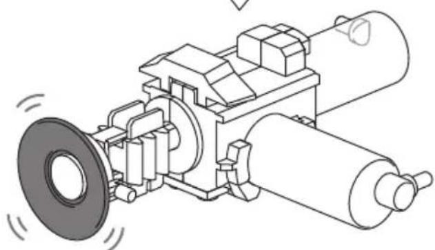
natural_image
Technical line drawing of a mechanical assembly with rollers and a flange (no text or symbols)15
natural_image
Technical line drawing of a mechanical assembly with gears and shafts (no text or symbols)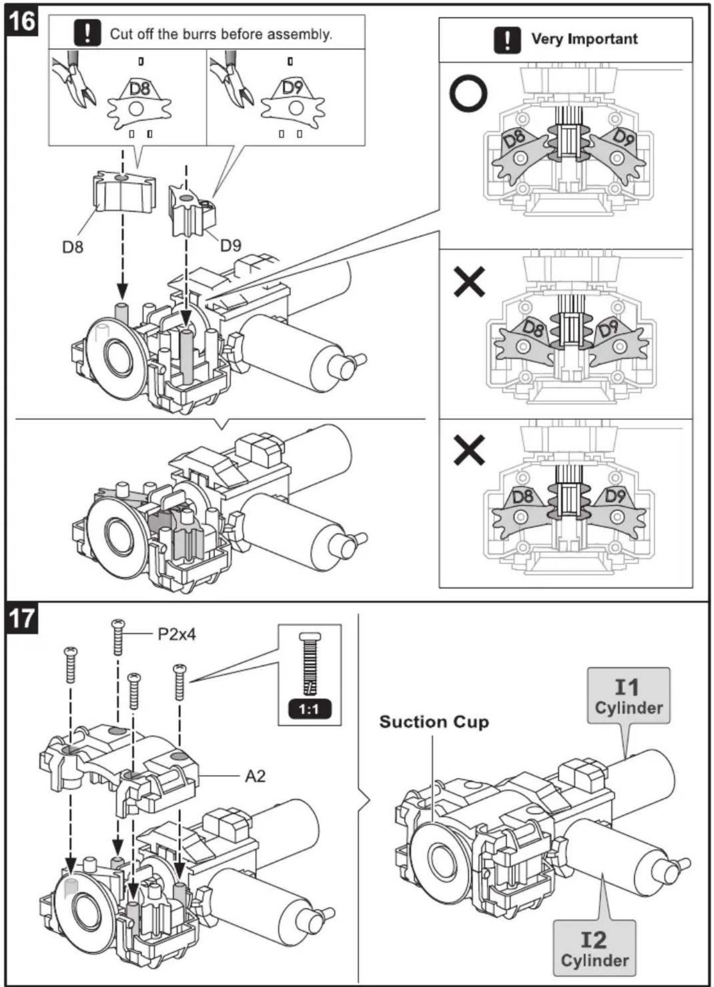
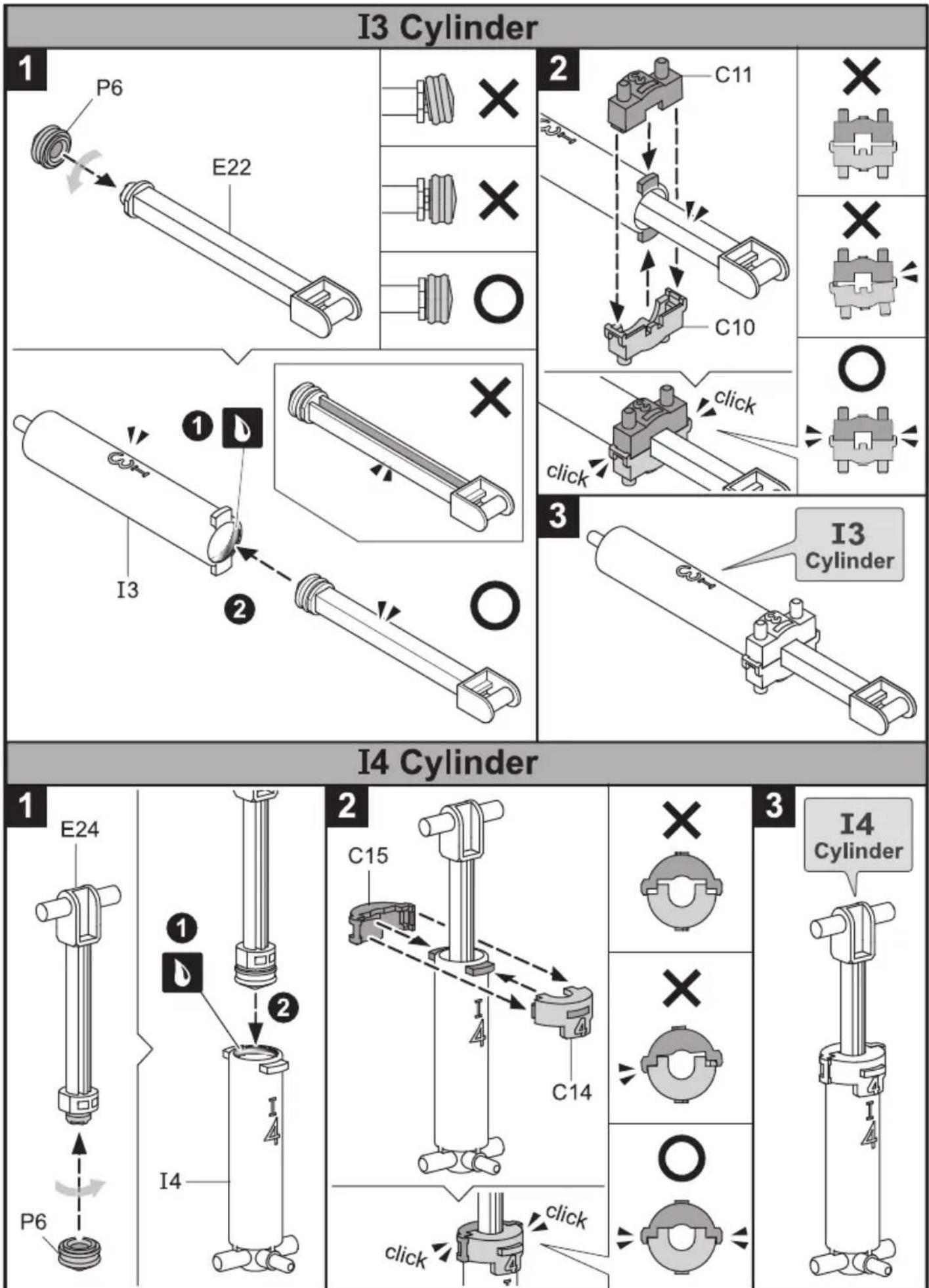
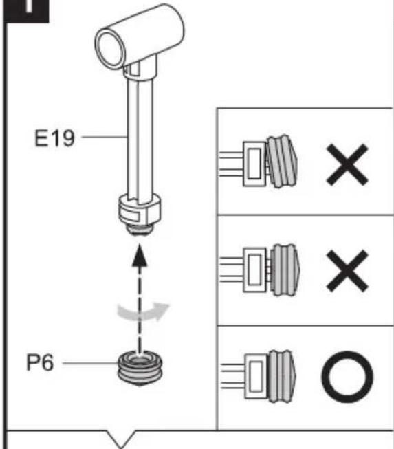
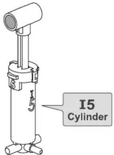
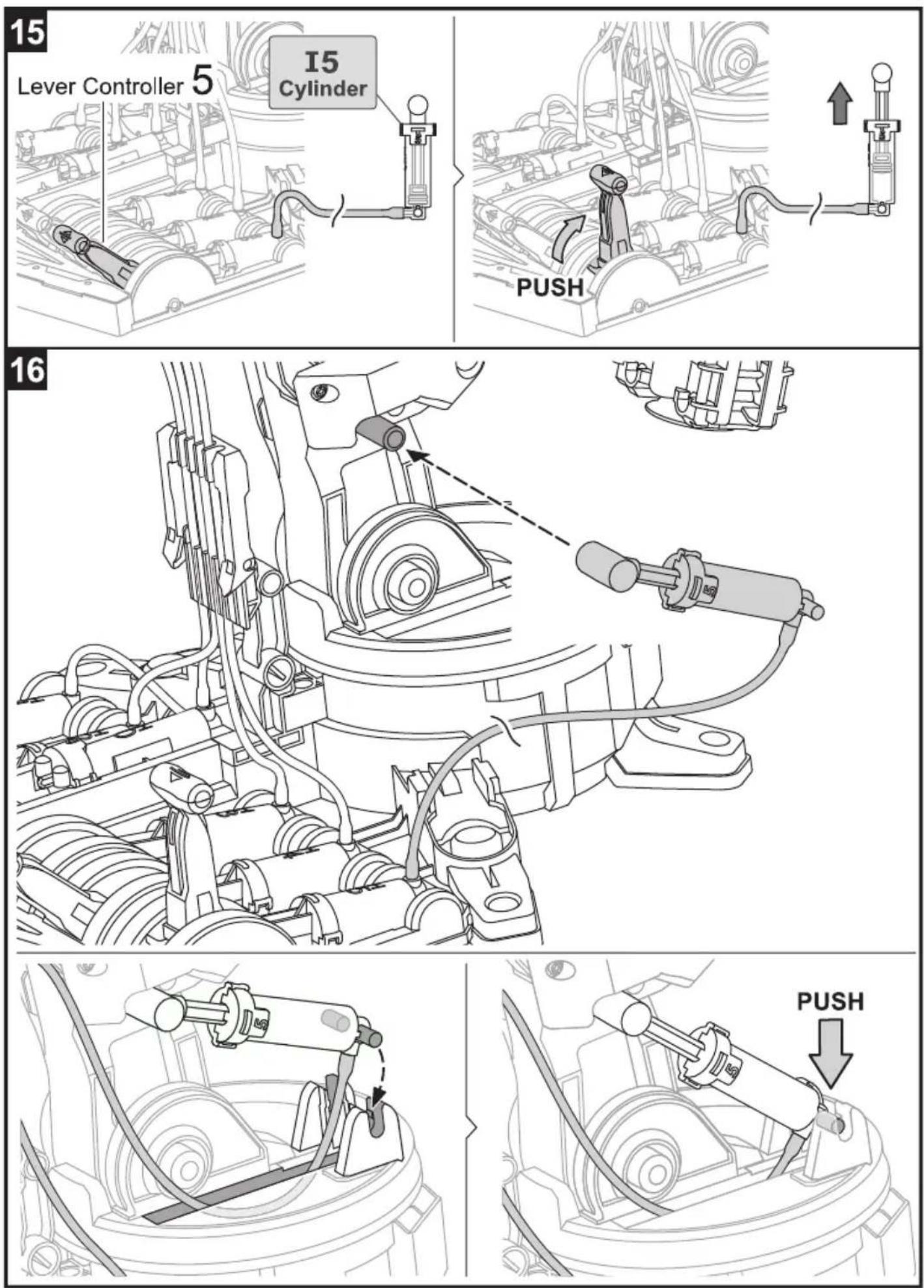
I5 Cylinder
1
2
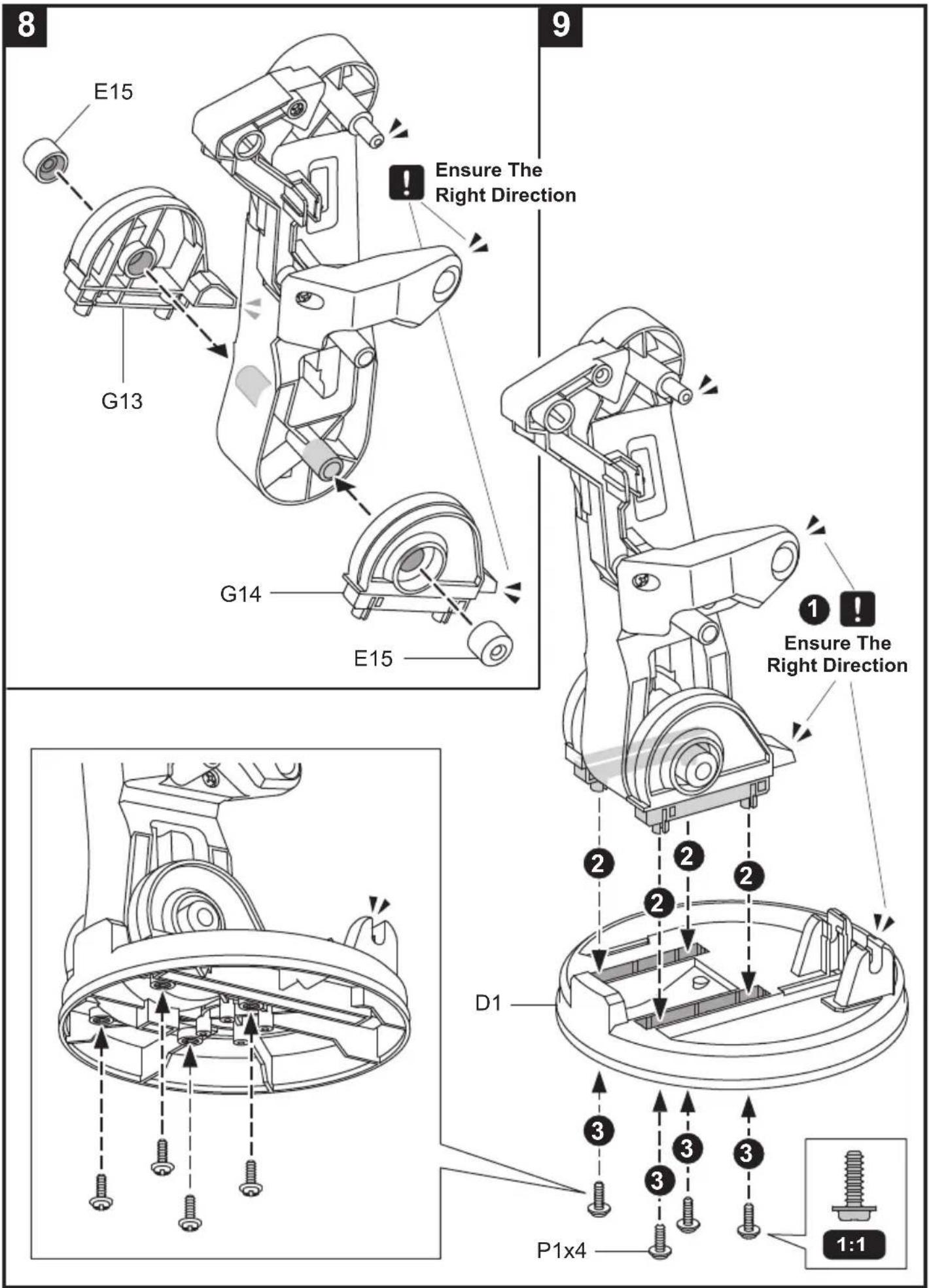
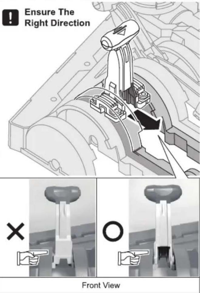
!
Ensure The Right Direction
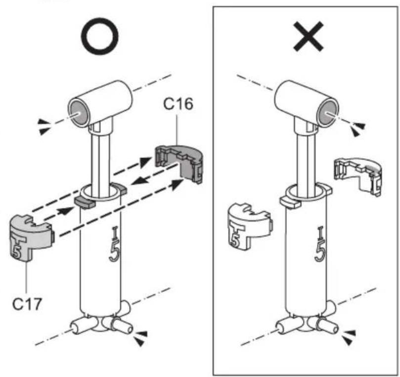
!
Ensure The Right Direction
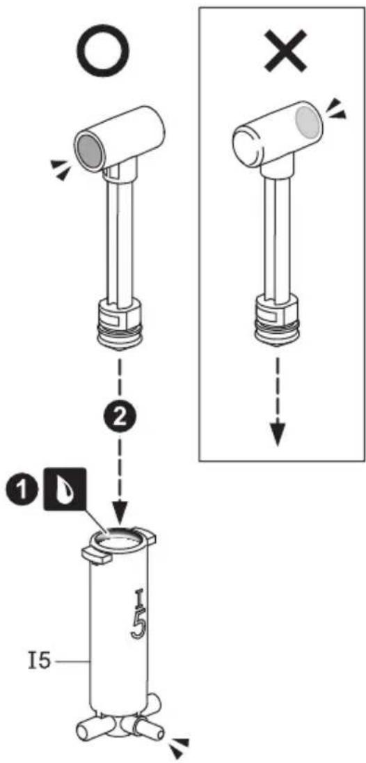
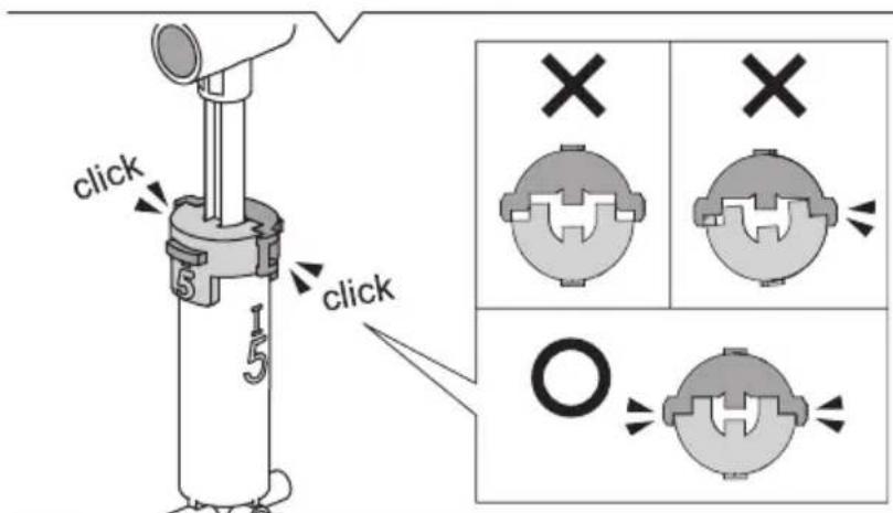
3
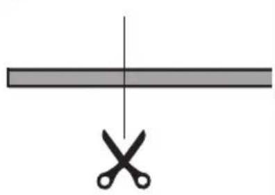
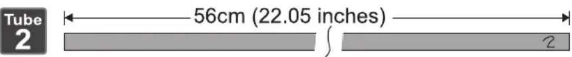
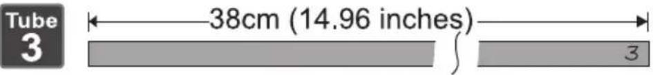
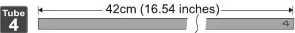
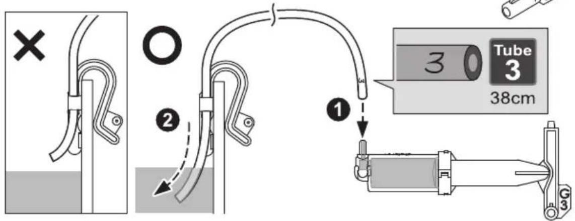
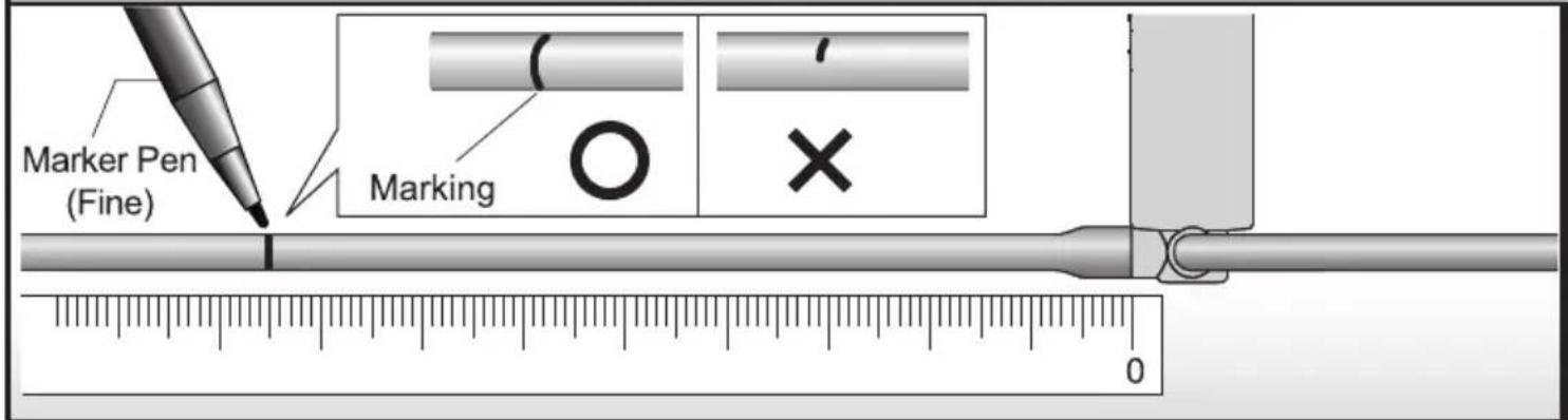
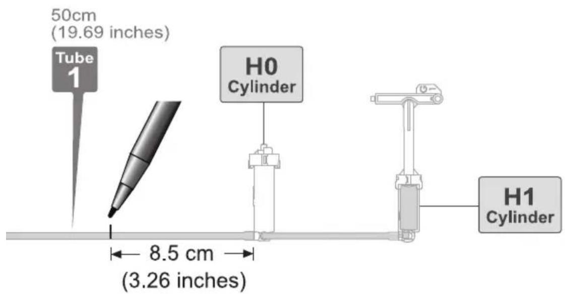
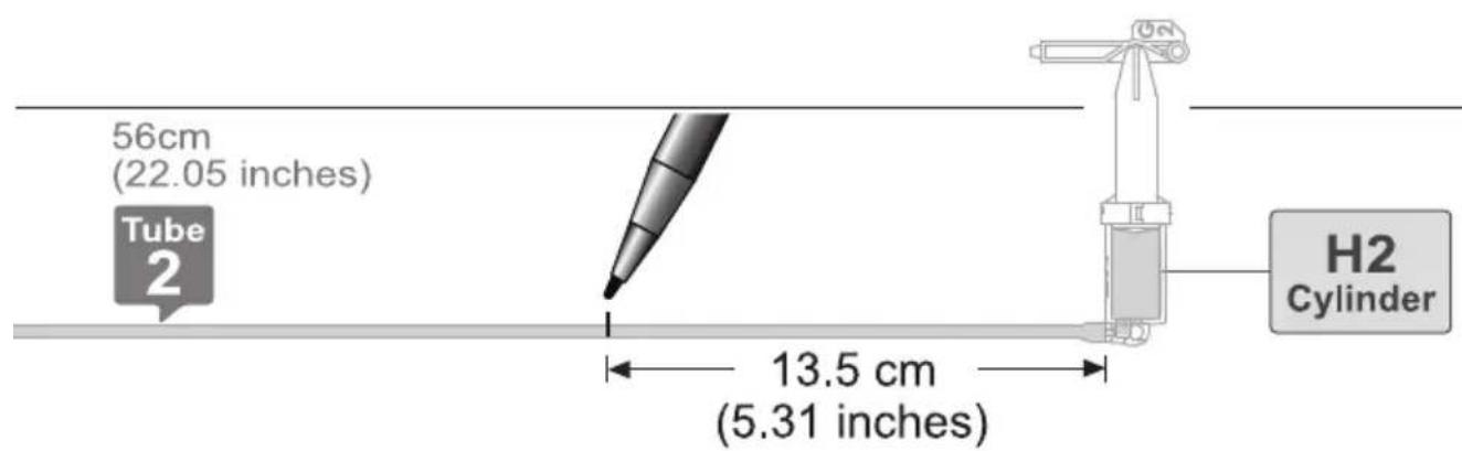
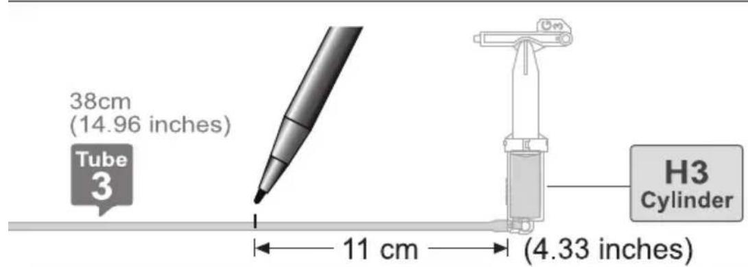
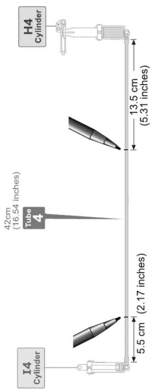
How To Cut The Tube
1 Measuring & Marking
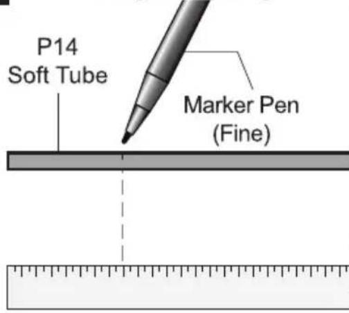
2 Cutting
natural_image
Simple diagram showing a horizontal bar intersected by a vertical line with two scissors below (no text or symbols)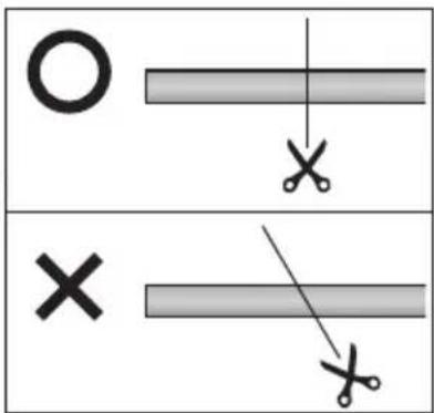
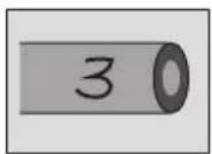
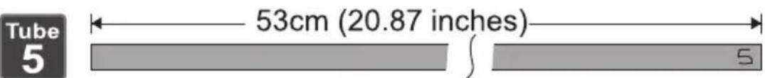
3 Coding
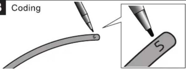
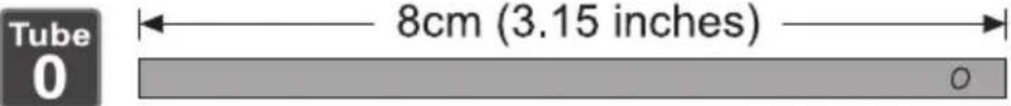
4 ! Use the same tube to cut Tube 1 & Tube 0. Images below not to scale

natural_image
Simple 3D illustration of a cylindrical object with a small circular hole, no text or symbols present.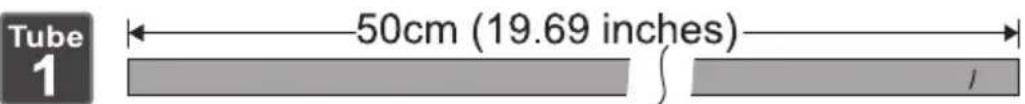


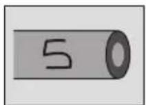
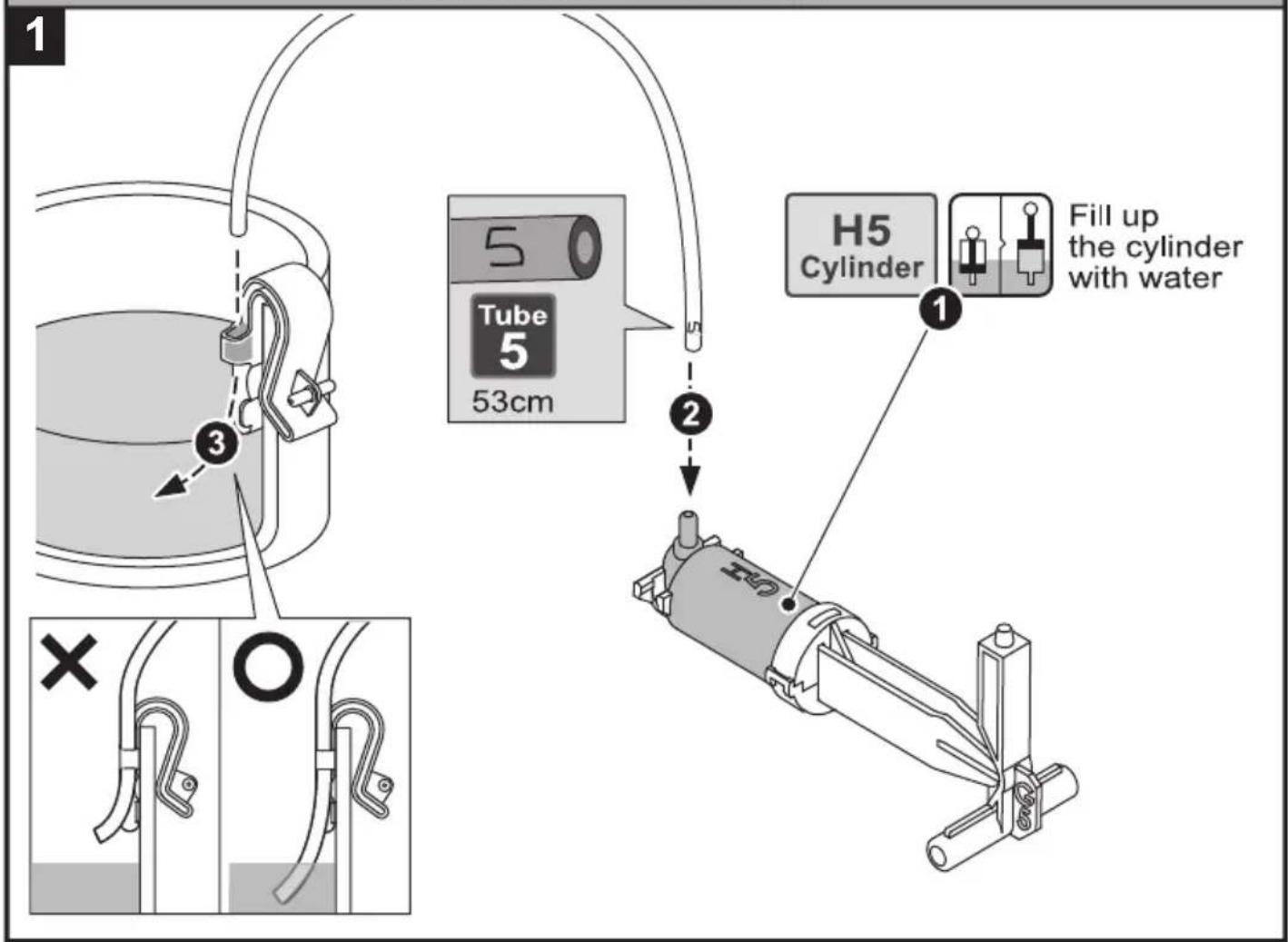
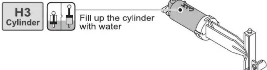
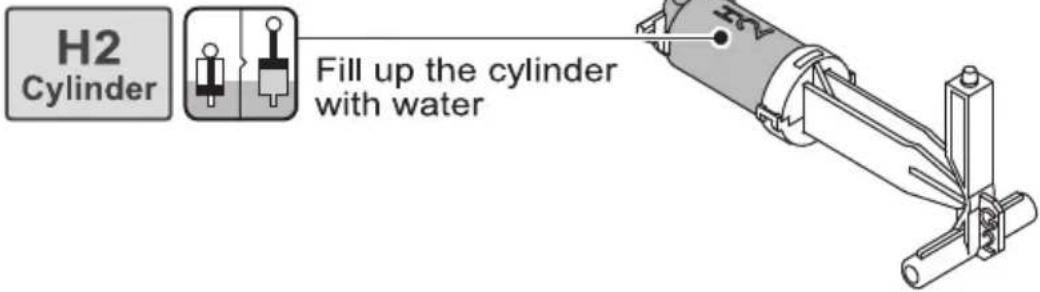
How To Fill Up The Cylinder With Water
1
Pour around a half cup of water
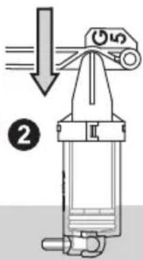
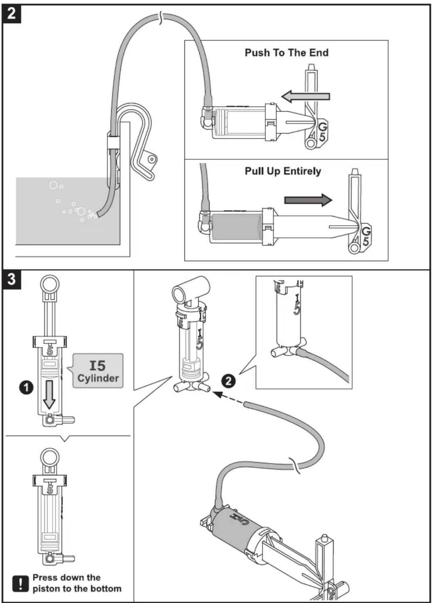
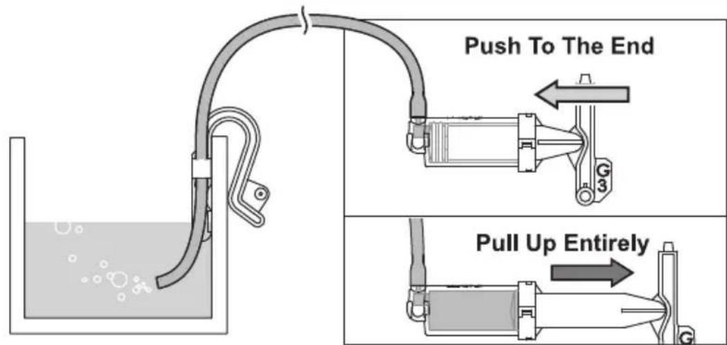
2
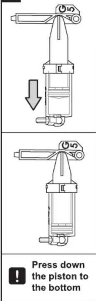

3


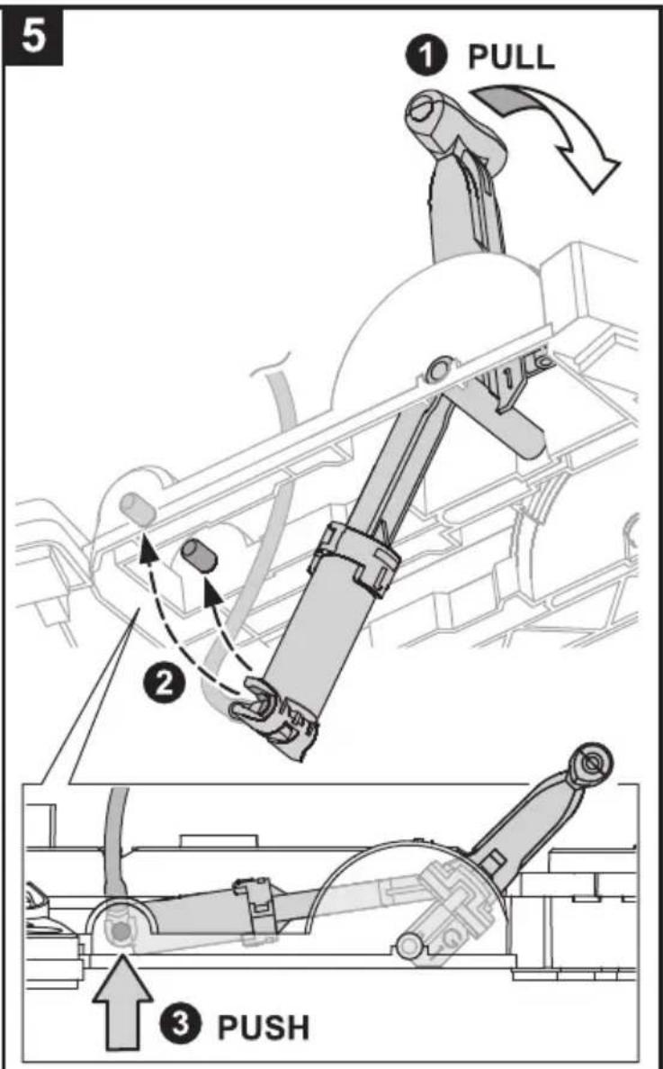
① Pull up the piston to the top (as shown above).
② Press down the piston to the bottom.
③ Re-do step 2&3 to fill up the cylinder with water.
4
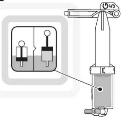
Note
Fill up the cylinder with water
when
appears.
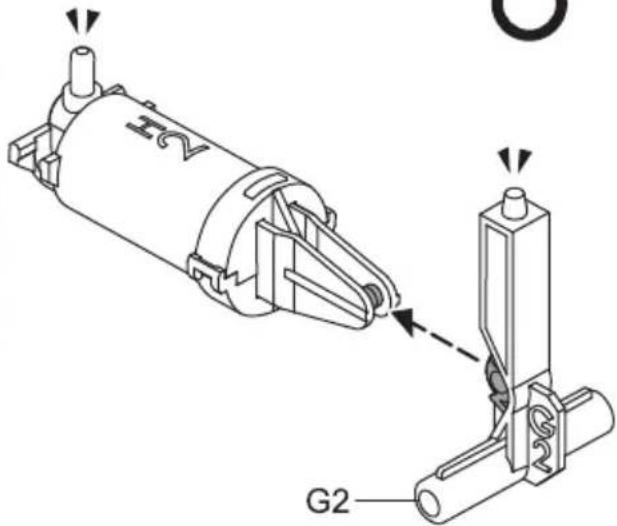
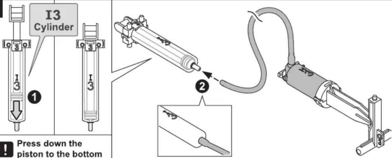
How To Fit Tube
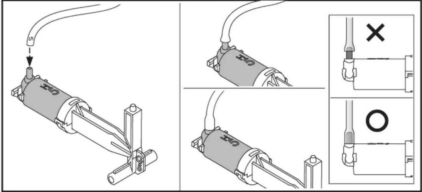
Hydraulic Cylinder Moduel Assembly
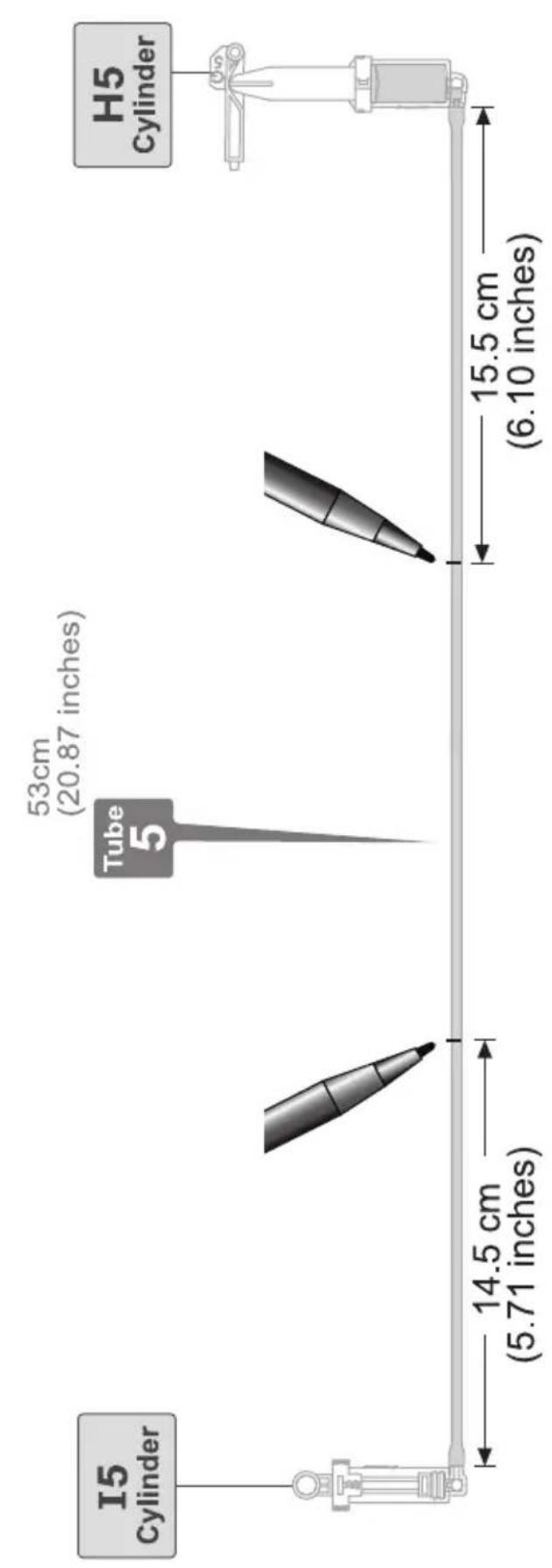
Connect H5 With 15
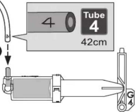
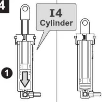
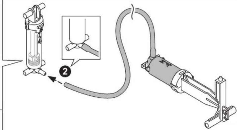
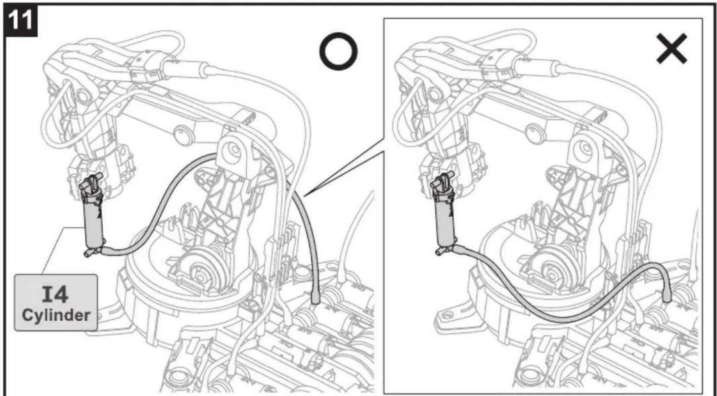
Connect H4 With I4
1
Fill up the cylinder with water
natural_image
Technical line drawing of a mechanical assembly with no visible text or symbols2
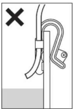
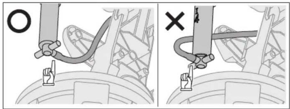
natural_image
Diagram showing a rope knot securing a vertical pole with a pull rod, marked with a black X (no text or symbols present)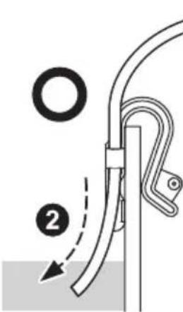
1
3
4
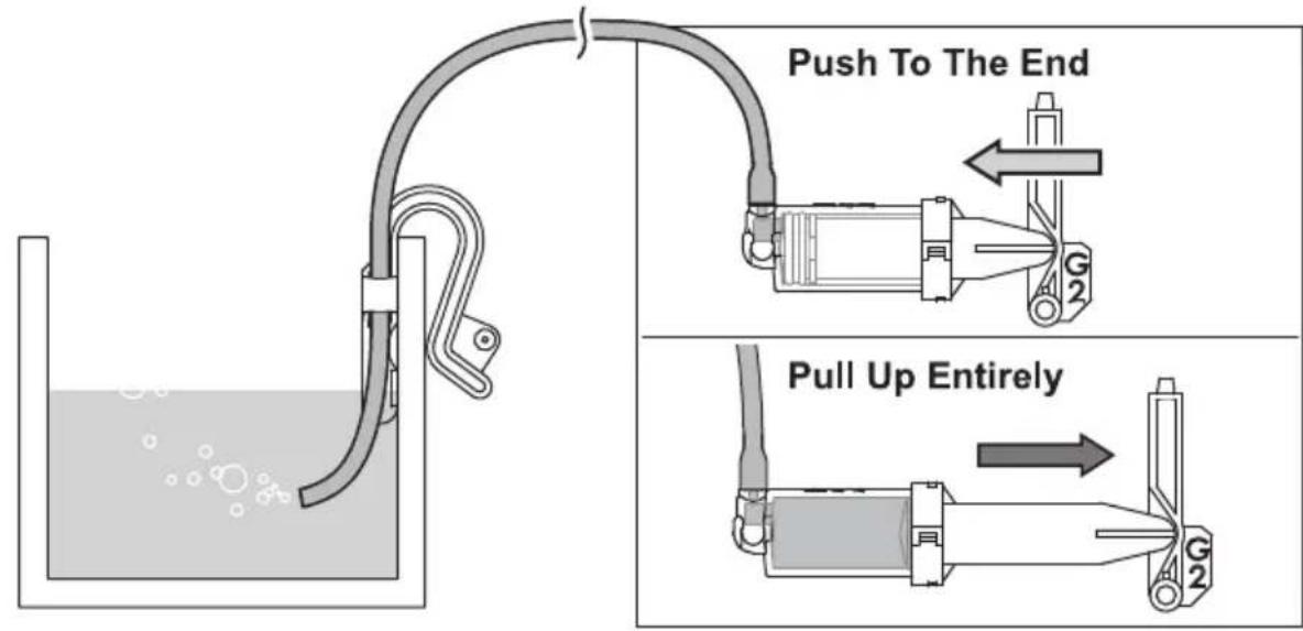
!
Press down the piston to the bottom
Connect H3 With I3
1
2
3
4
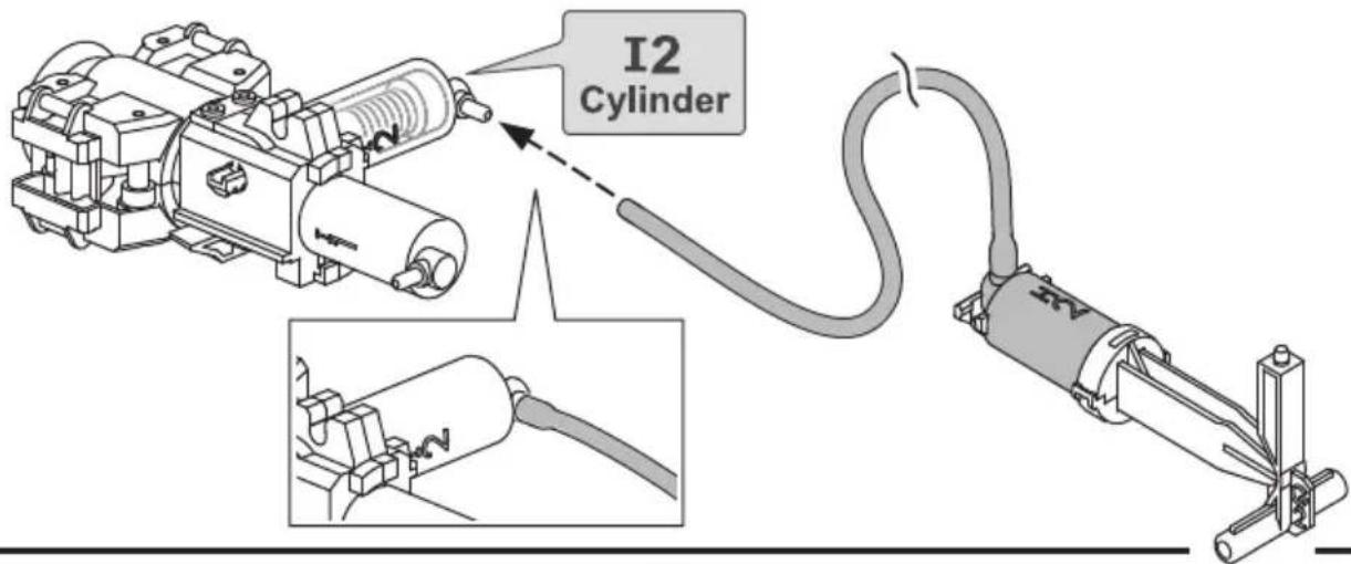
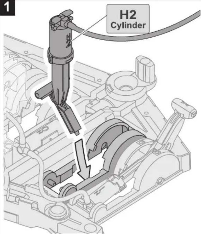
Connect H2 With I2
1
2
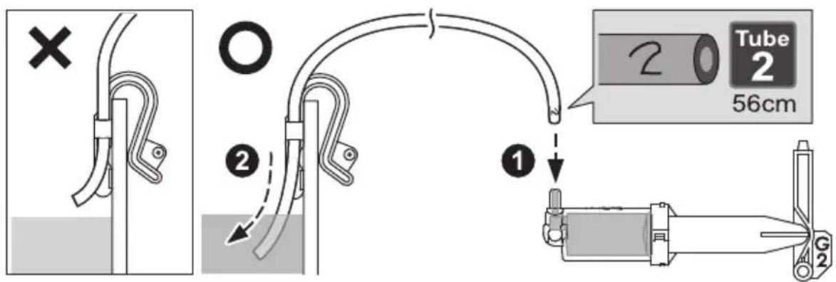
3
4
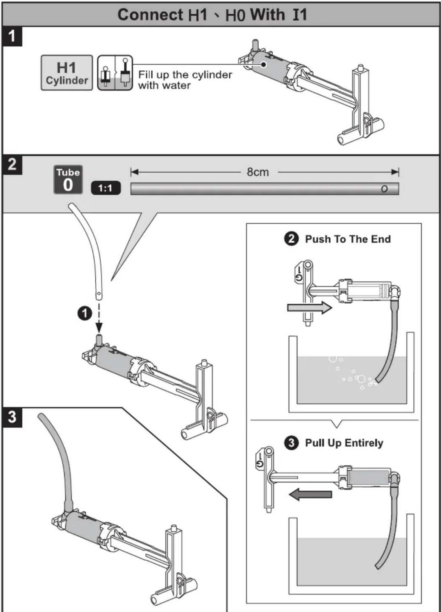
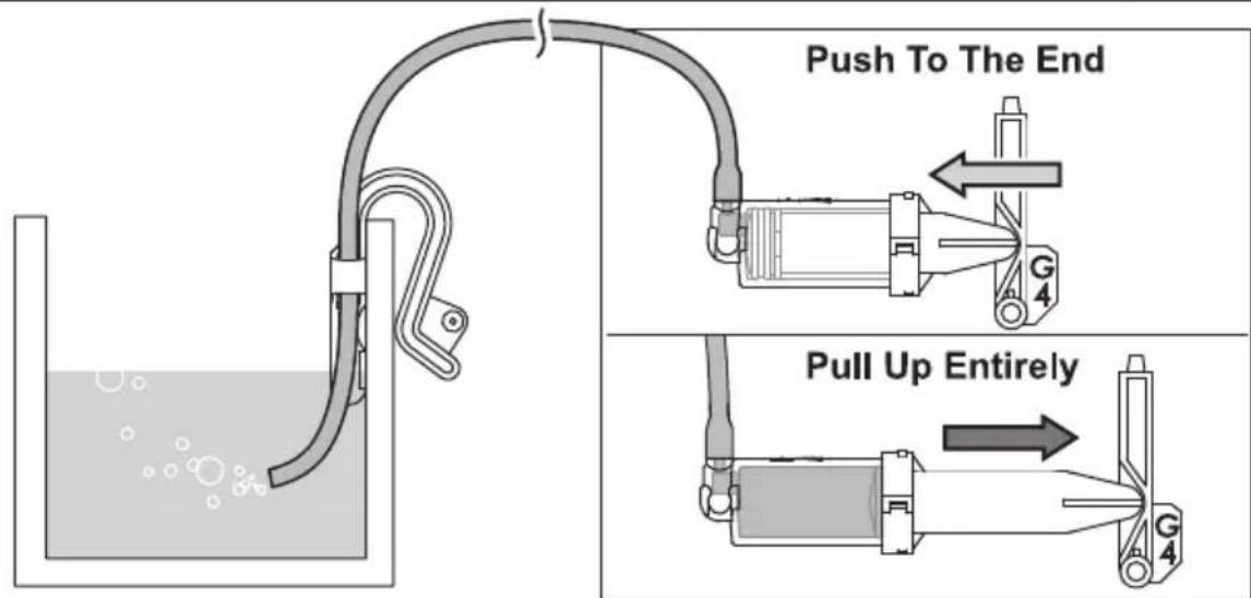
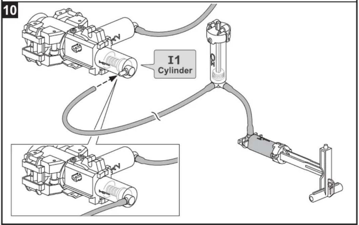
flowchart
graph TD
    A["Connect H1、H0 With I1"] --> B["H1 Cylinder"]
    B --> C["Fill up the cylinder with water"]
    C --> D["Tube 0 1:1"]
    D --> E["8cm"]
    F["Push To The End"] --> G["Water in liquid"]
    H["Pull Up Entirely"] --> I["Water in liquid"]
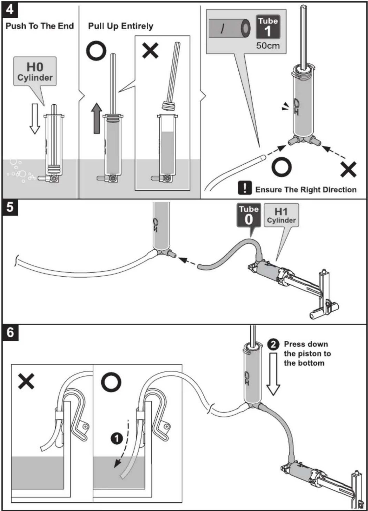
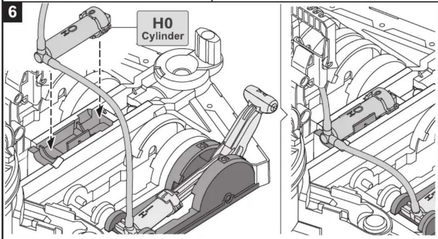
7
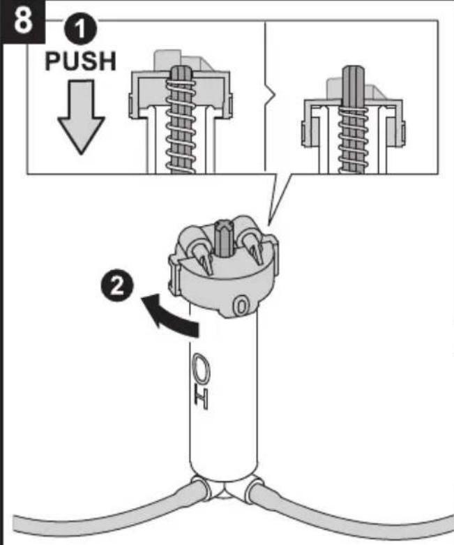
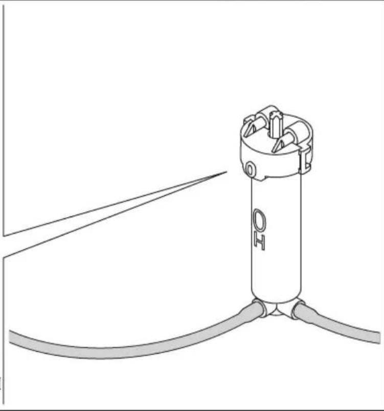
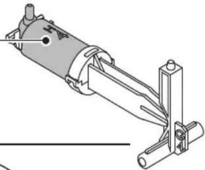
natural_image
Line drawing of a cylindrical device with two cables and a label 'OH' on top (no text or symbols beyond the label)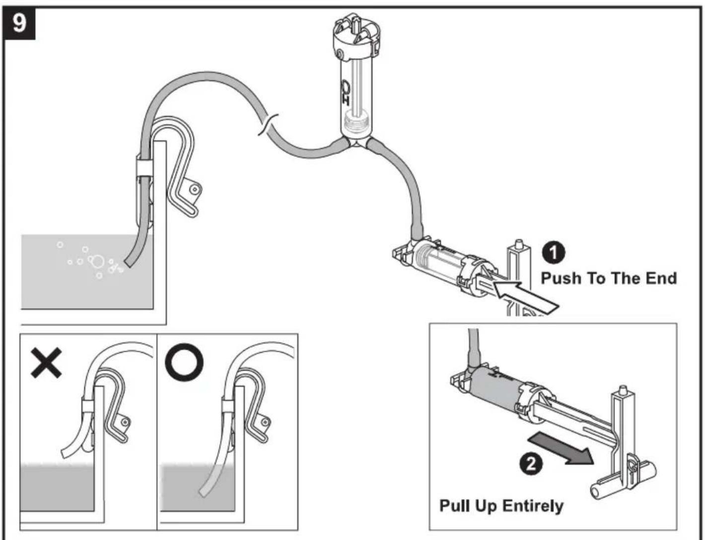
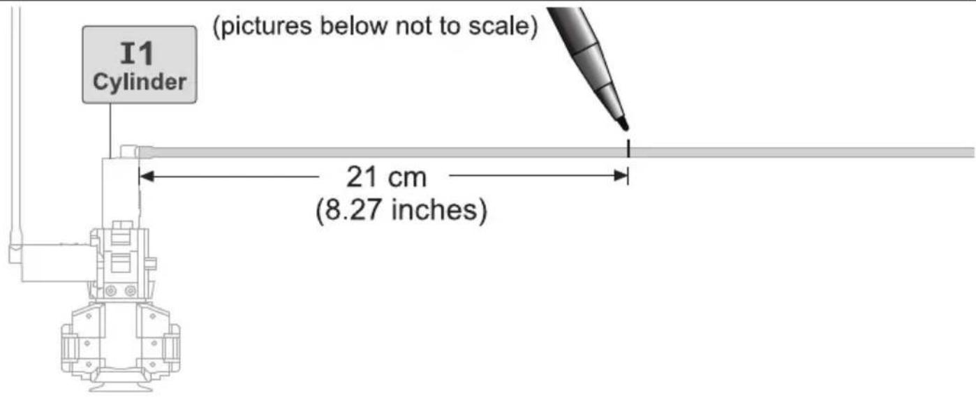
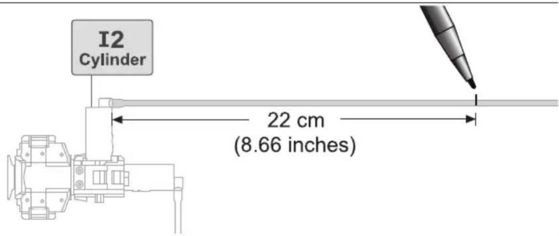
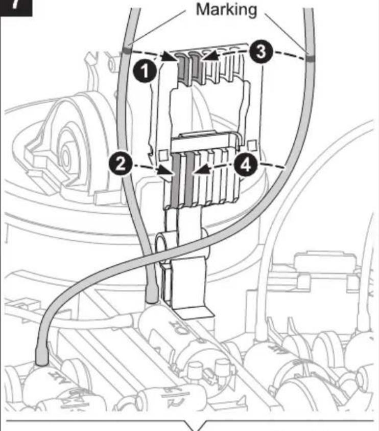
Measuring & Marking
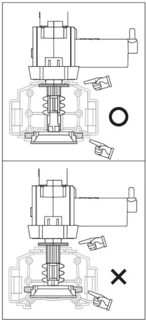
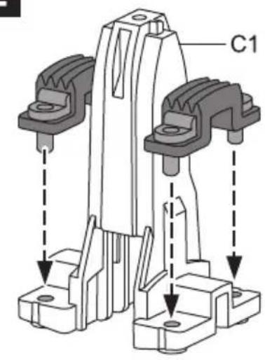
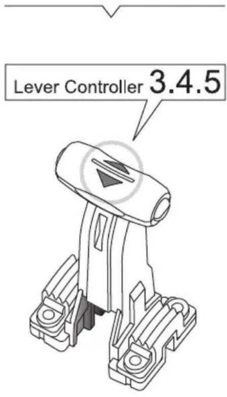
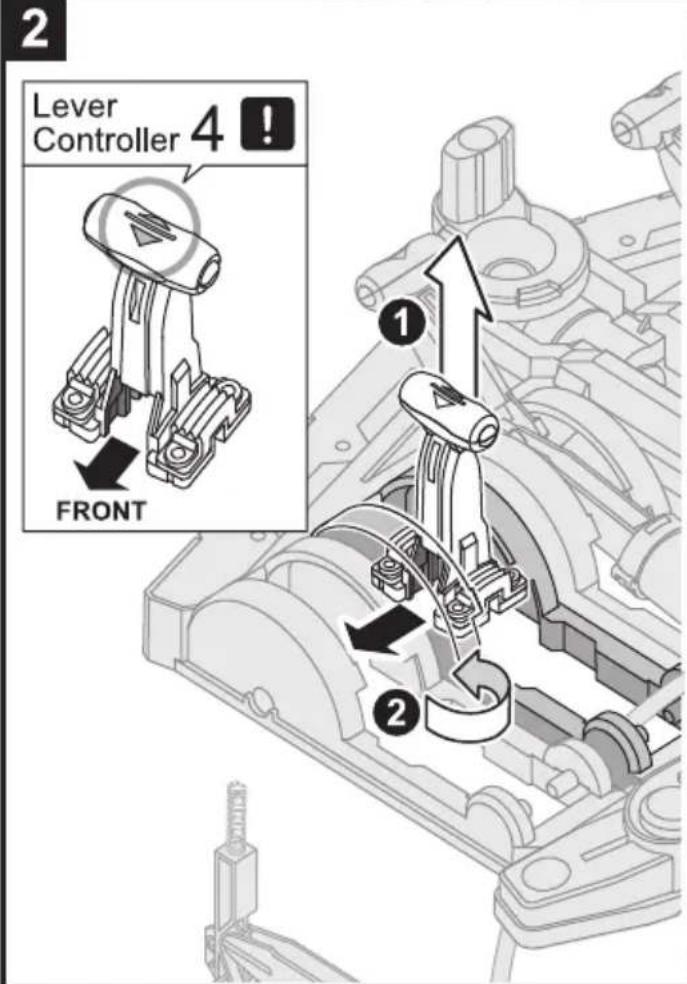
Lever Controller Assembly

Very Important! P5 (Brake Pad) must be clean and not stained by oil. Make sure to hand clean and dry P5 before assembly.
1
2
natural_image
Technical line drawing of a mechanical component assembly (no text or symbols)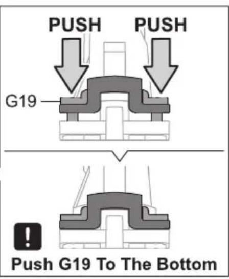
3
4
5

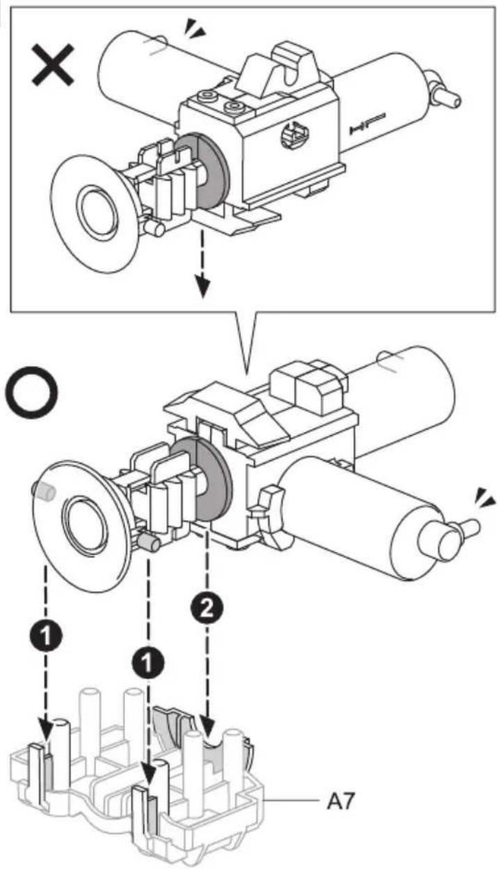
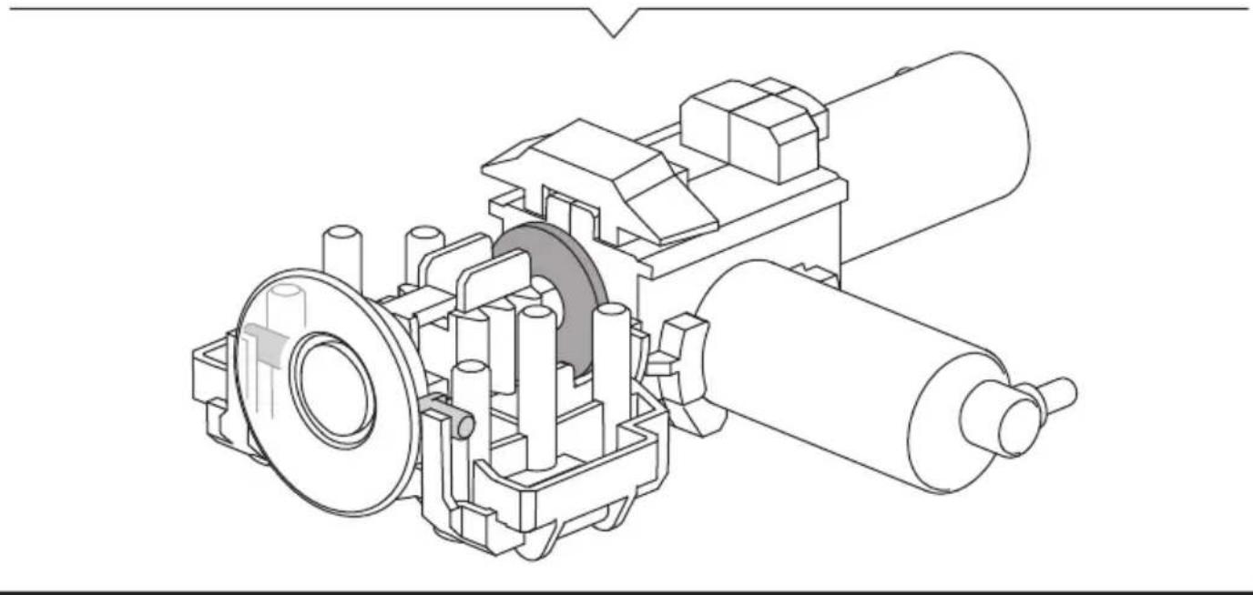
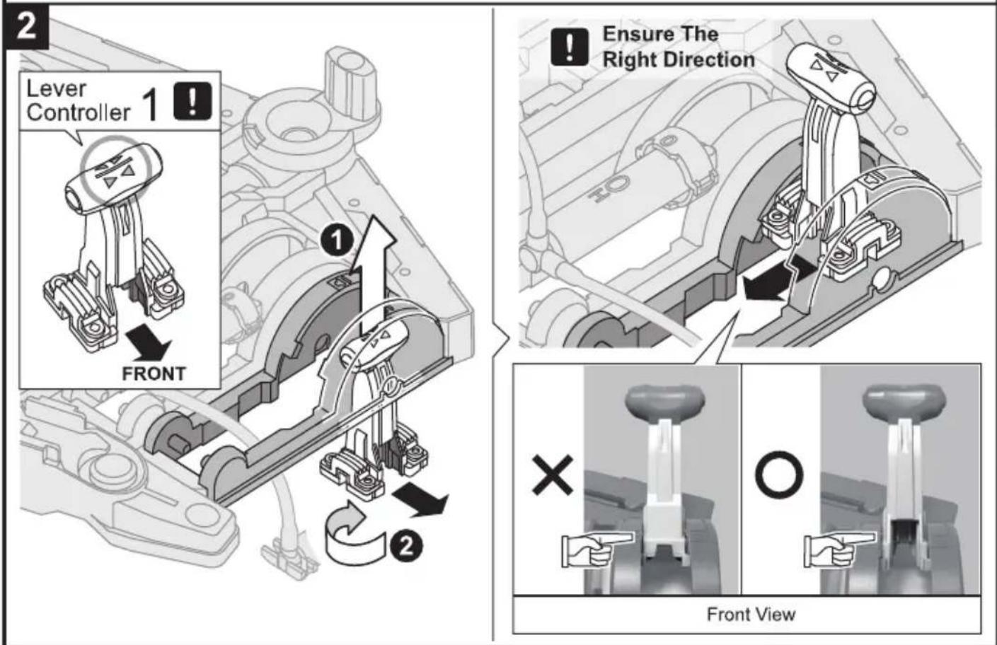
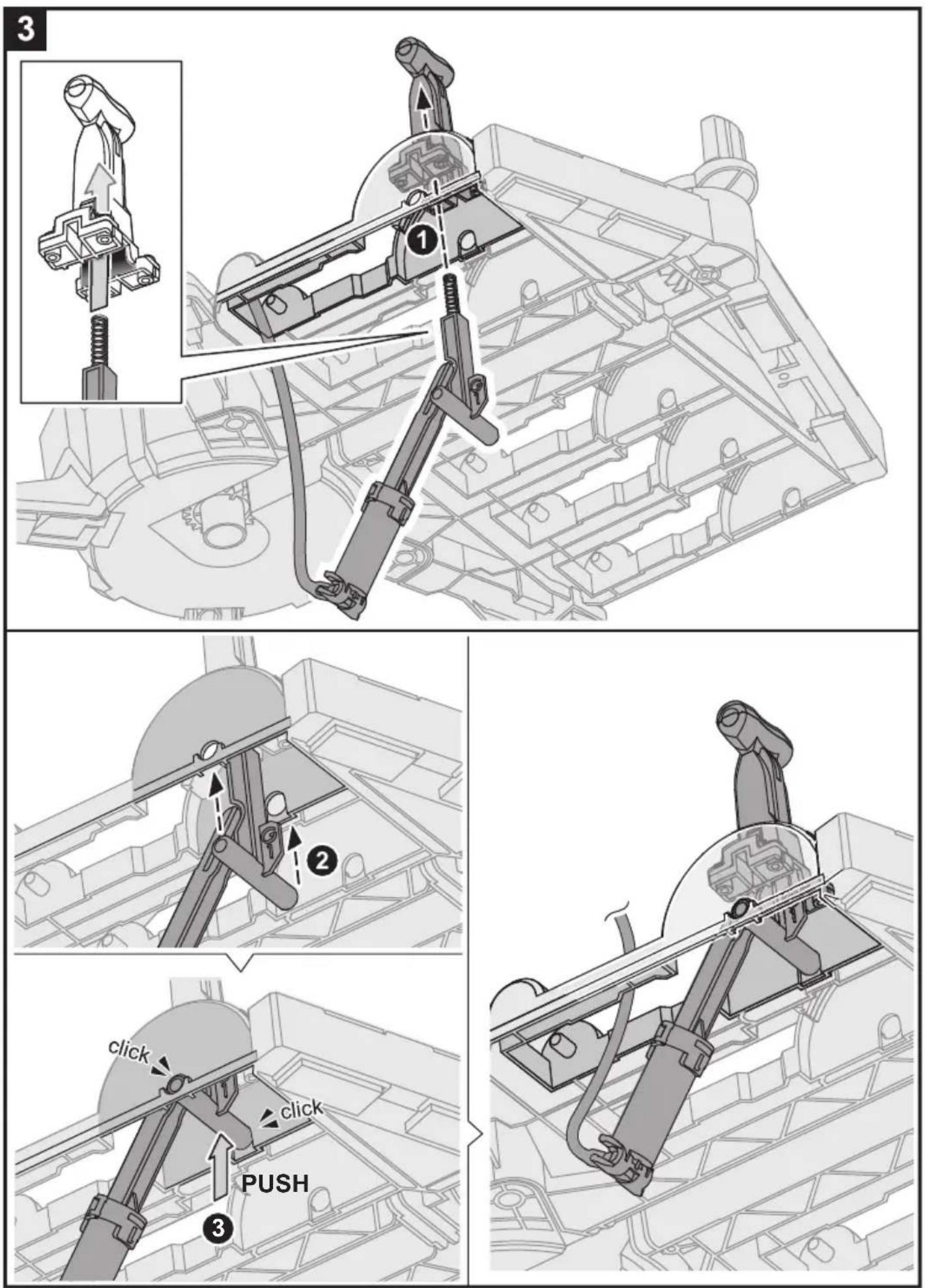
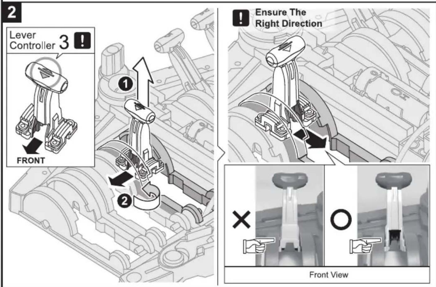
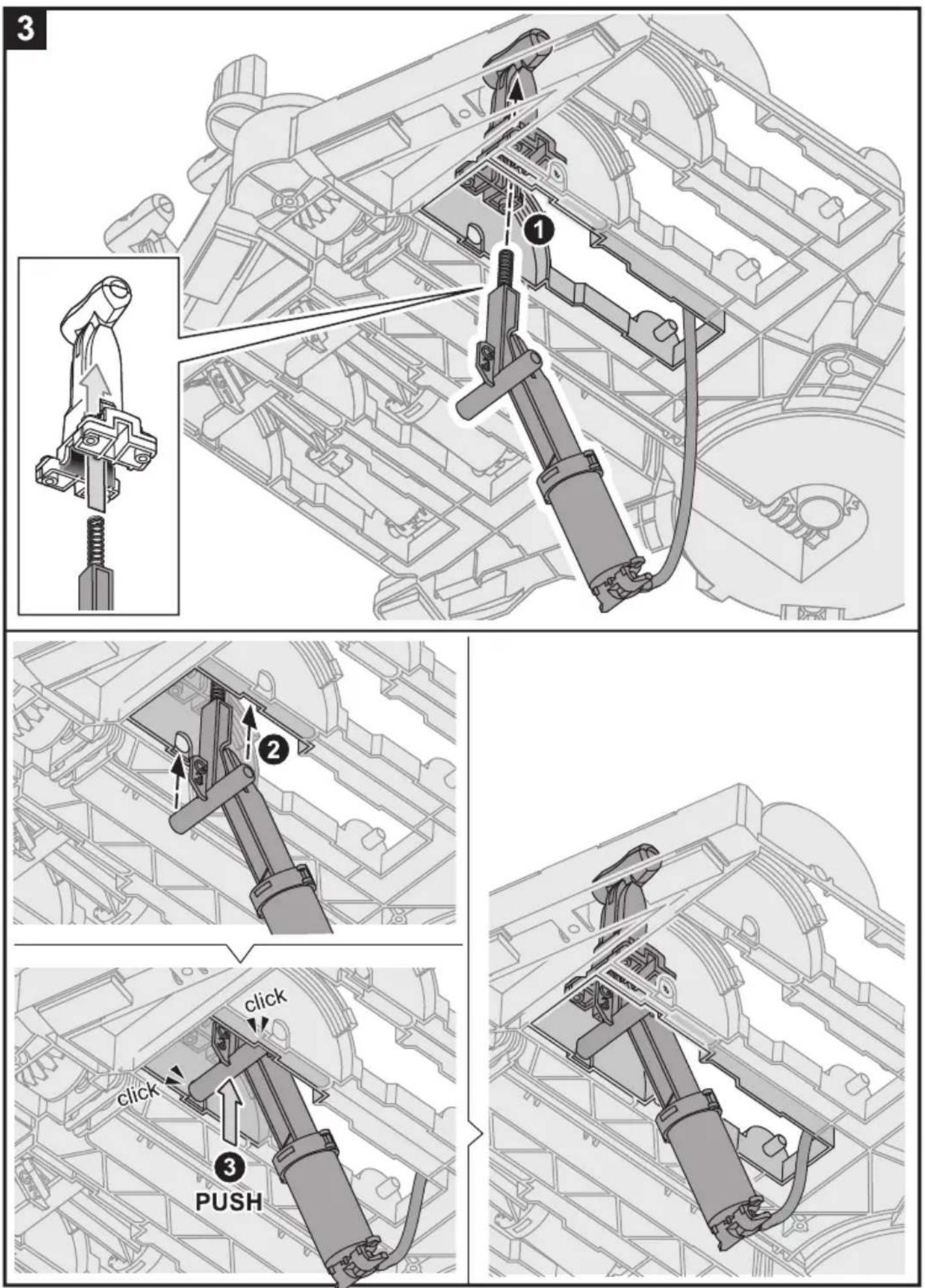
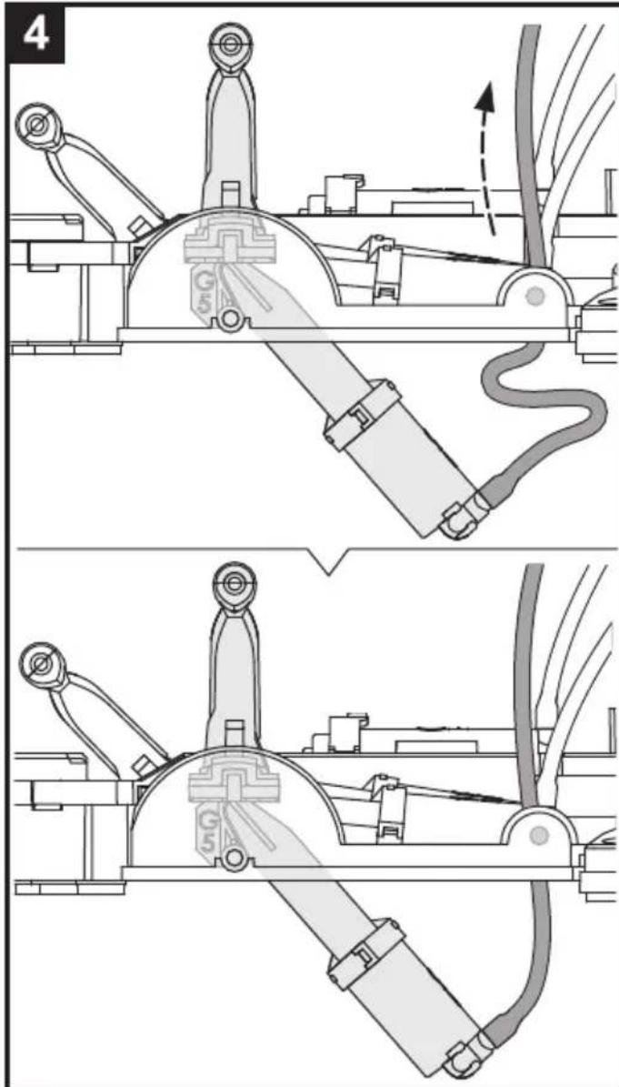
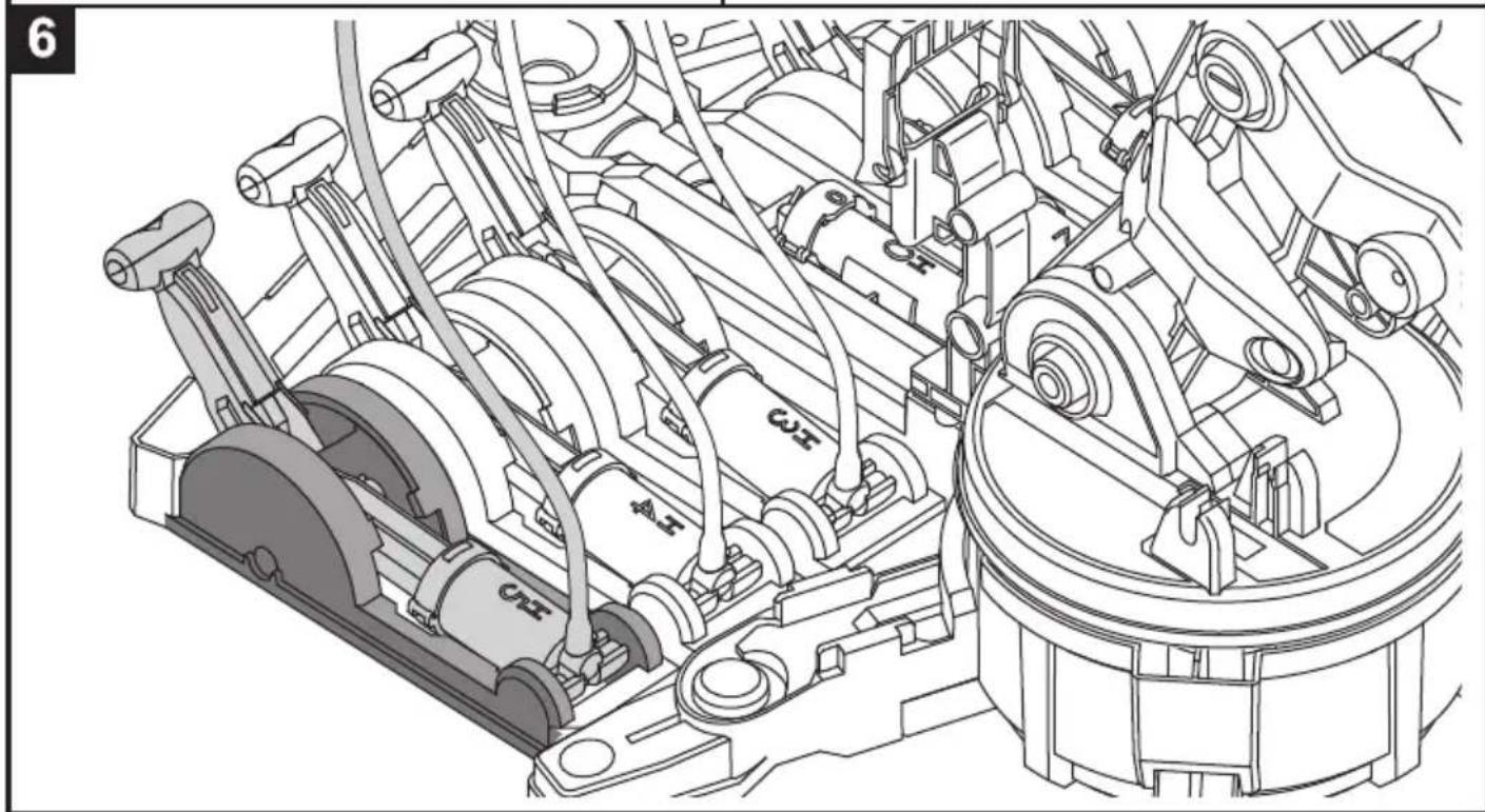
Control Moduel Assembly
Unit 1: H0.H1 Cylinder & Lever Controller 1
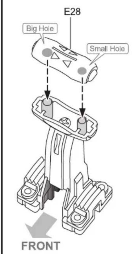
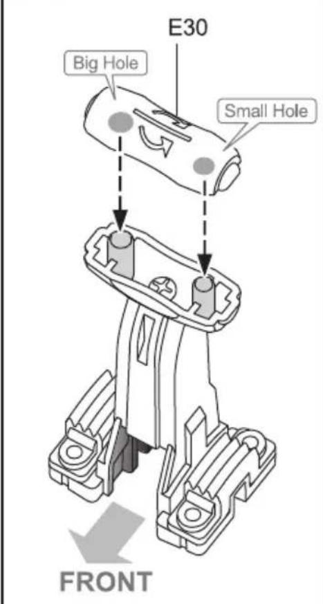
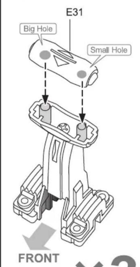
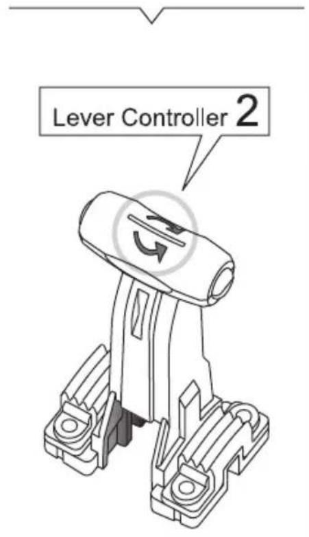
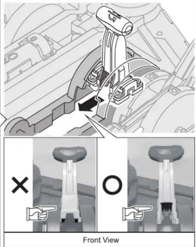
Unit 2: H2 Cylinder & Lever Controller 2
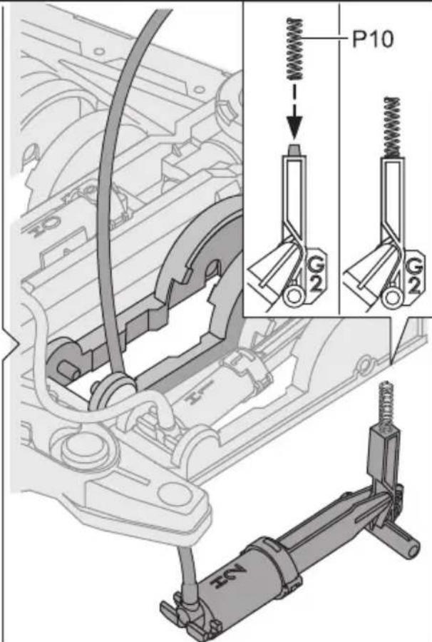
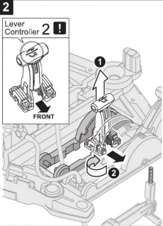
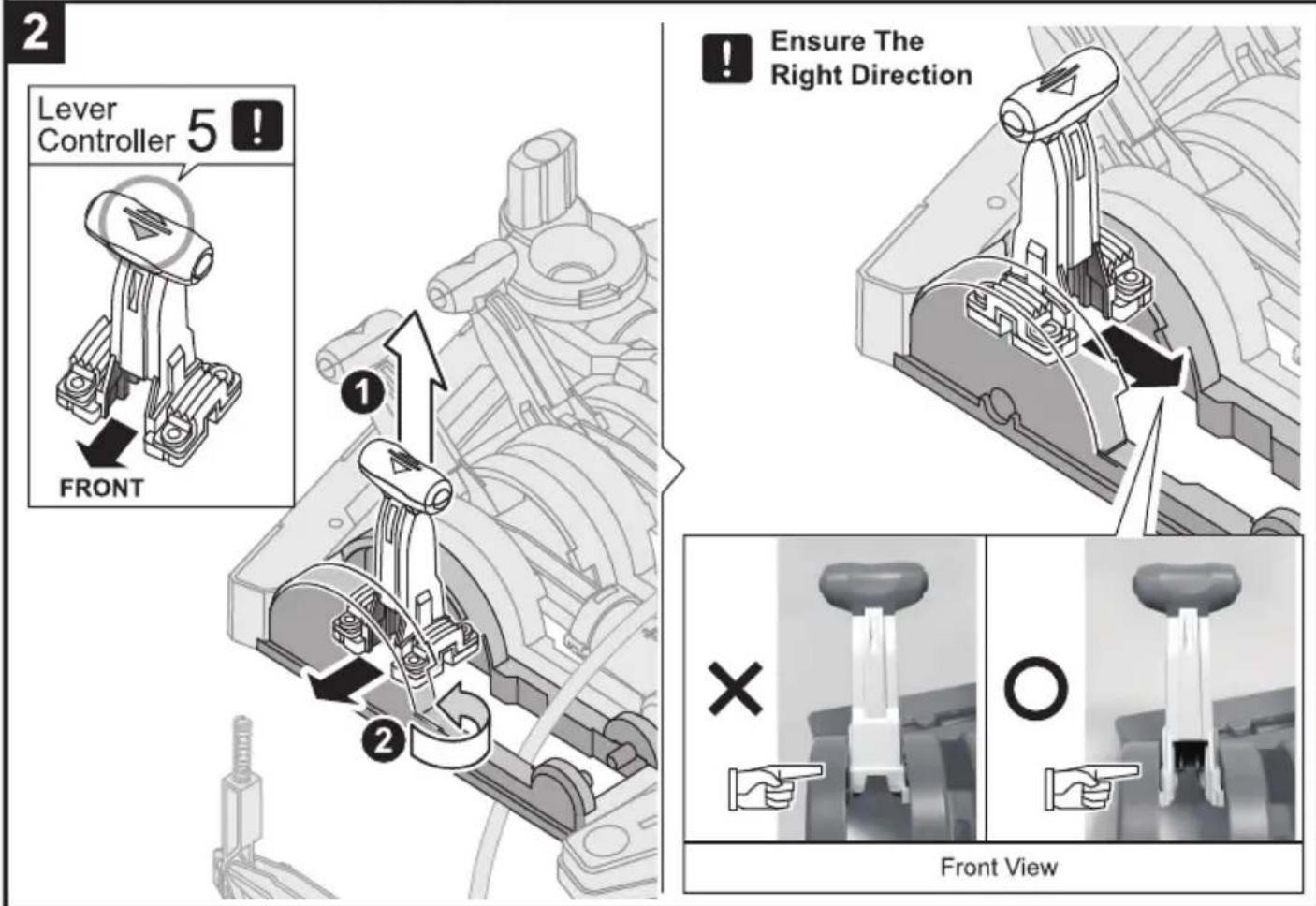
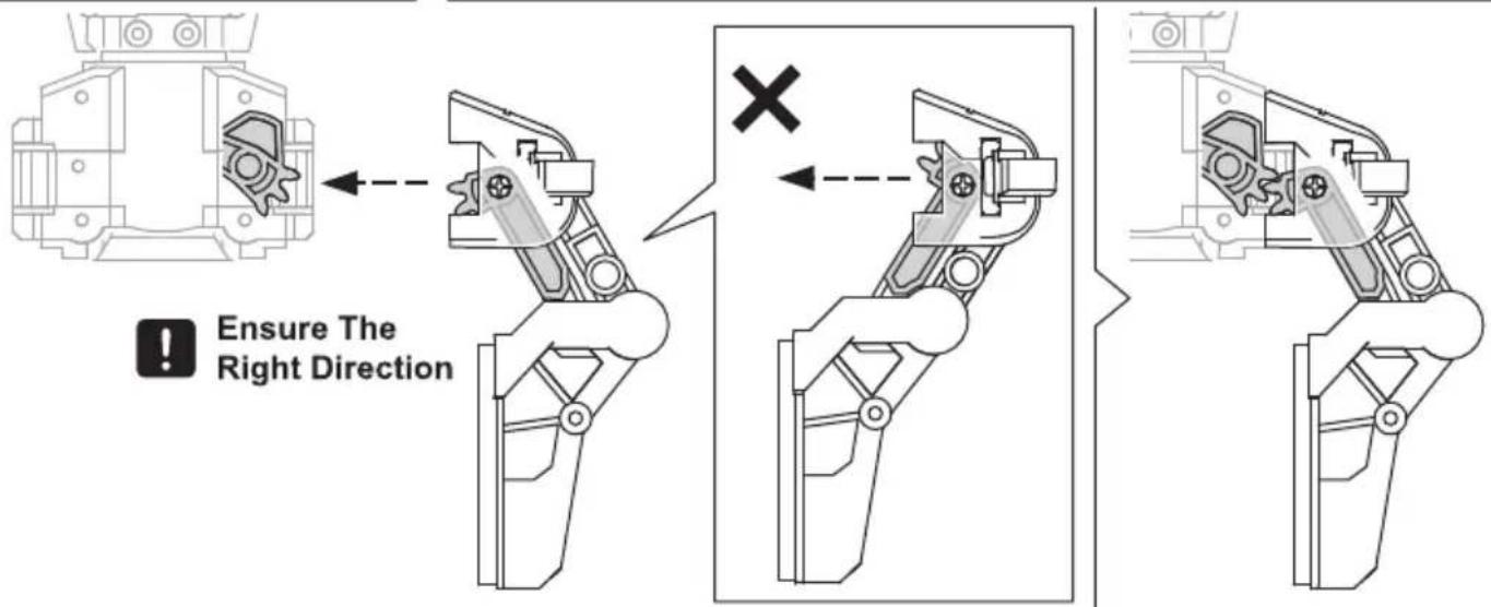
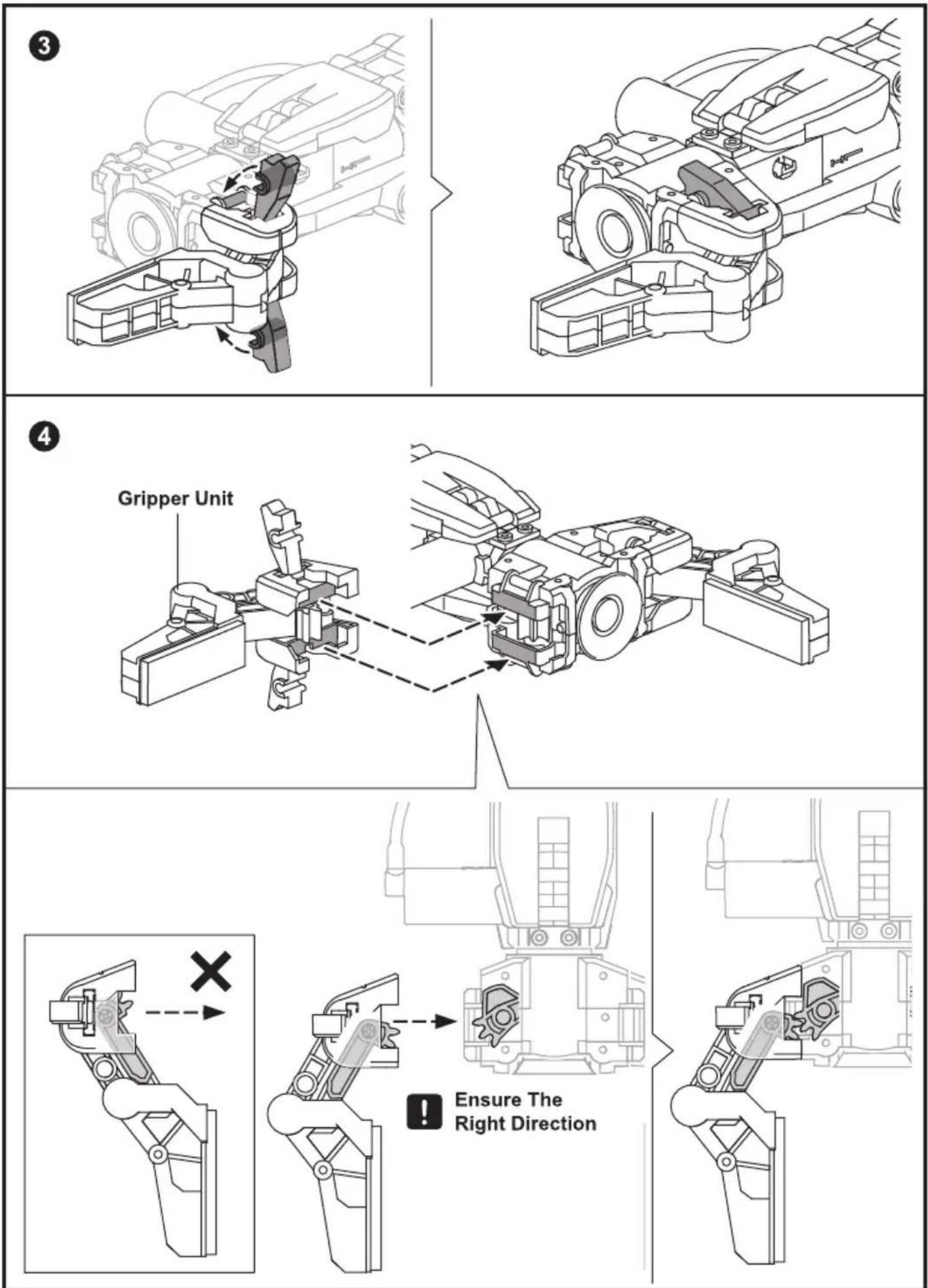
!
Ensure The Right Direction
natural_image
Technical line drawing of an internal combustion engine cylinder assembly (no text or labels)Unit 3: H3 Cylinder & Lever Controller 3
natural_image
Technical line drawings of mechanical components, showing assembly and assembly steps (no text or symbols)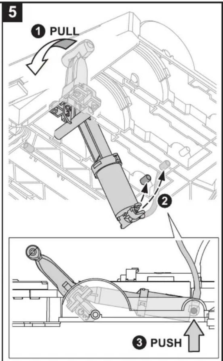
natural_image
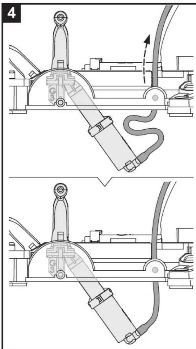
Technical line drawing of a mechanical assembly with gears and linkages (no text or symbols)Unit 4: H4 Cylinder & Lever Controller 4
1
natural_image
Technical line drawings of mechanical components, showing assembly and assembly steps (no text or symbols)
natural_image
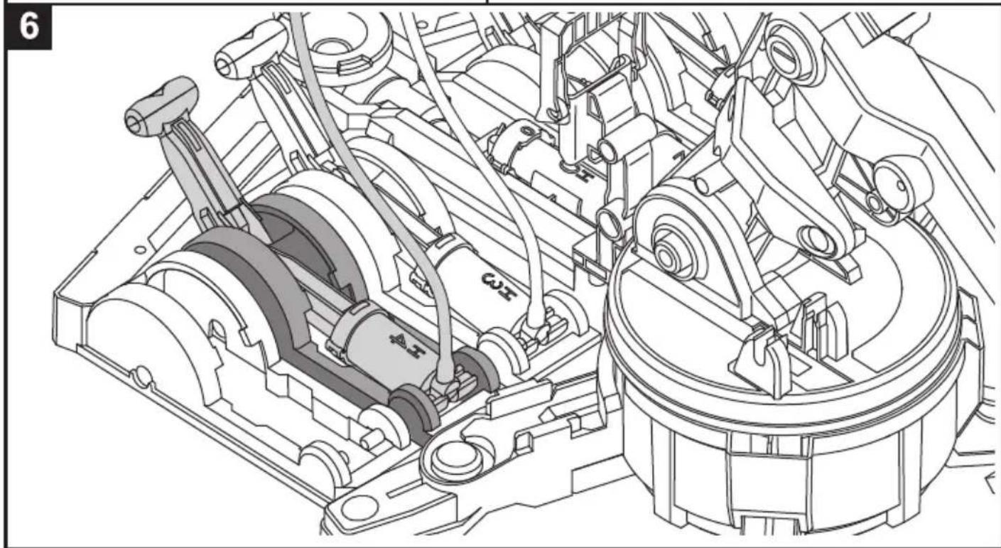
Technical line drawing of a mechanical assembly with gears and linkages (no text or symbols)Unit 5: H5 Cylinder & Lever Controller 5
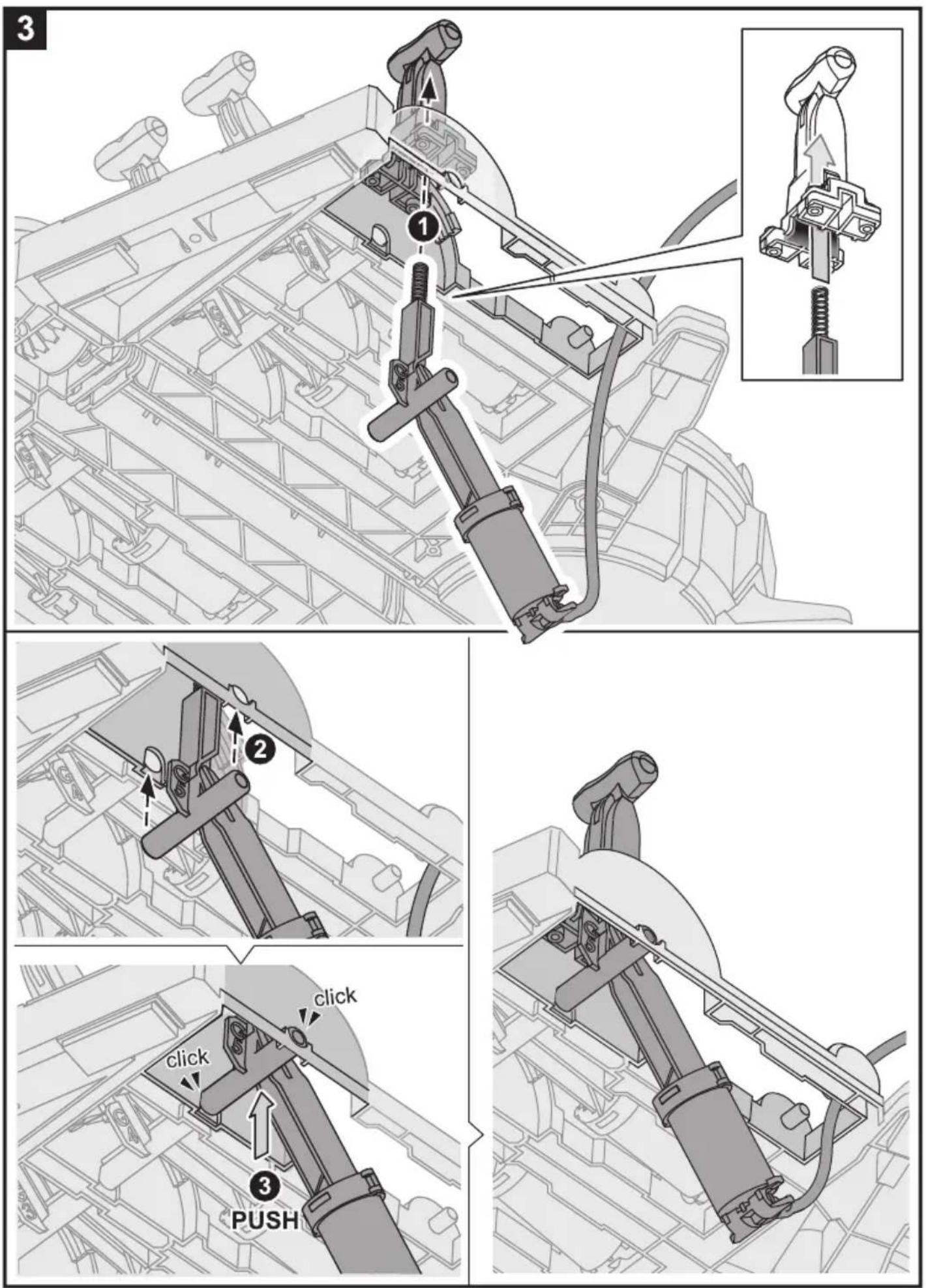
natural_image
Technical line drawings of a mechanical device with no visible text or symbols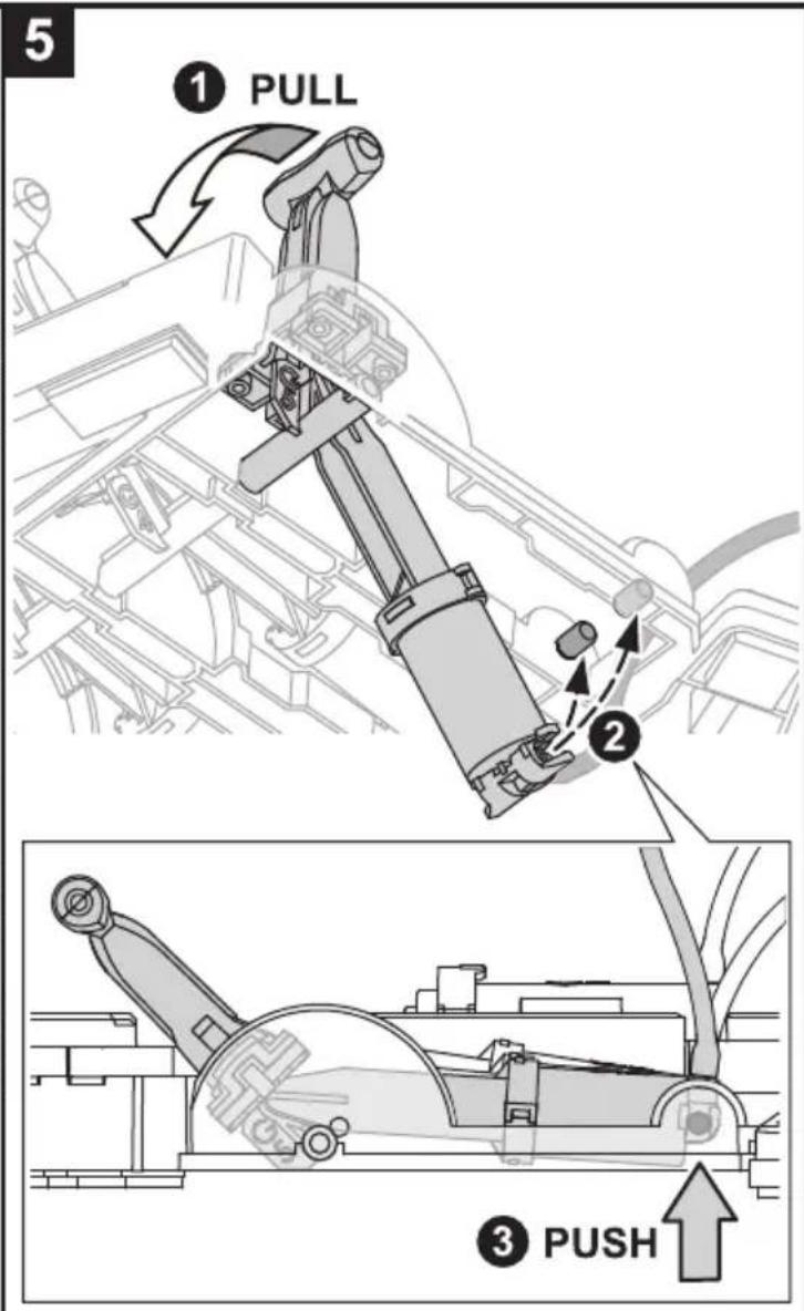
natural_image
Technical line drawing of an internal combustion engine cylinder assembly (no text or labels)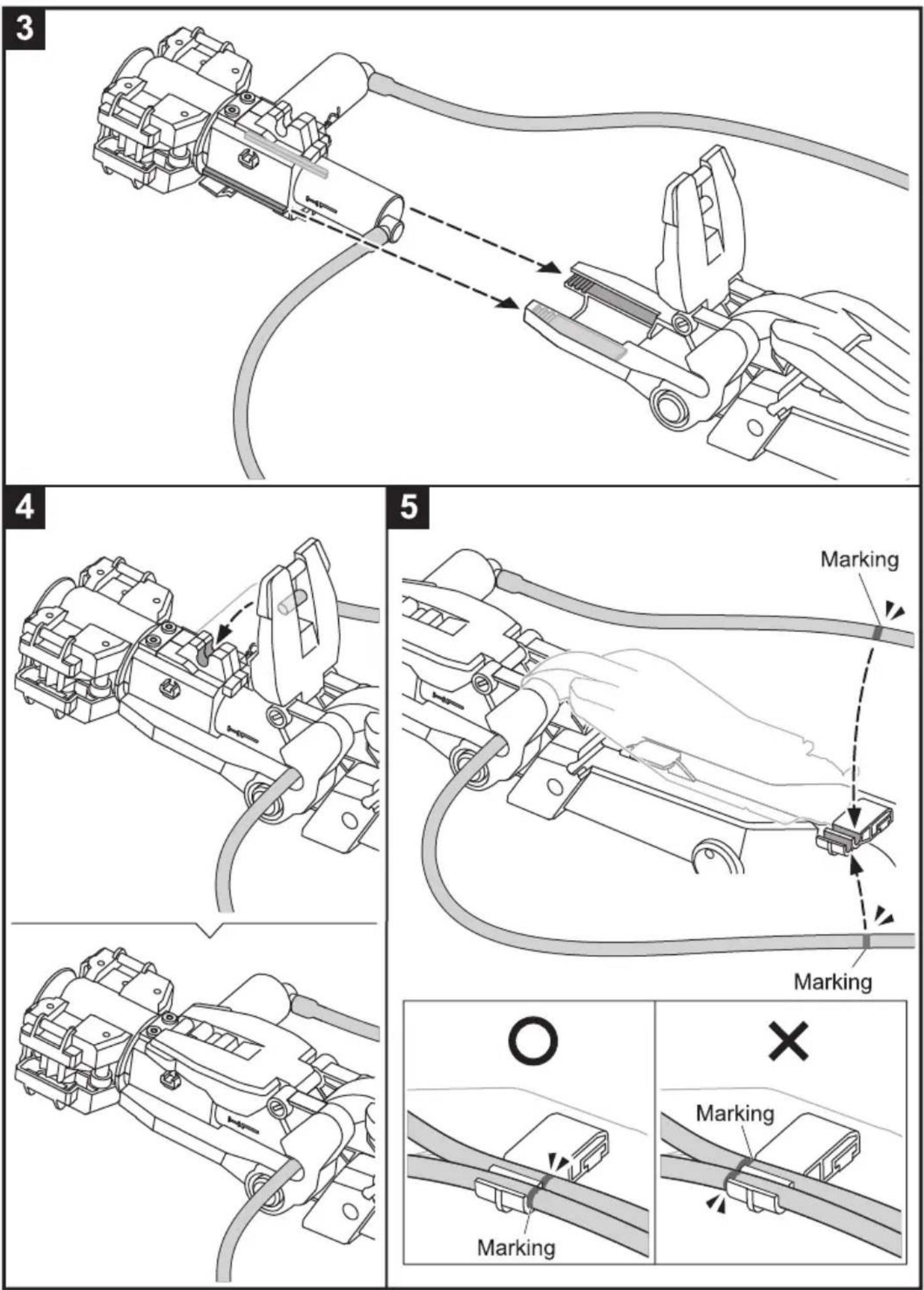
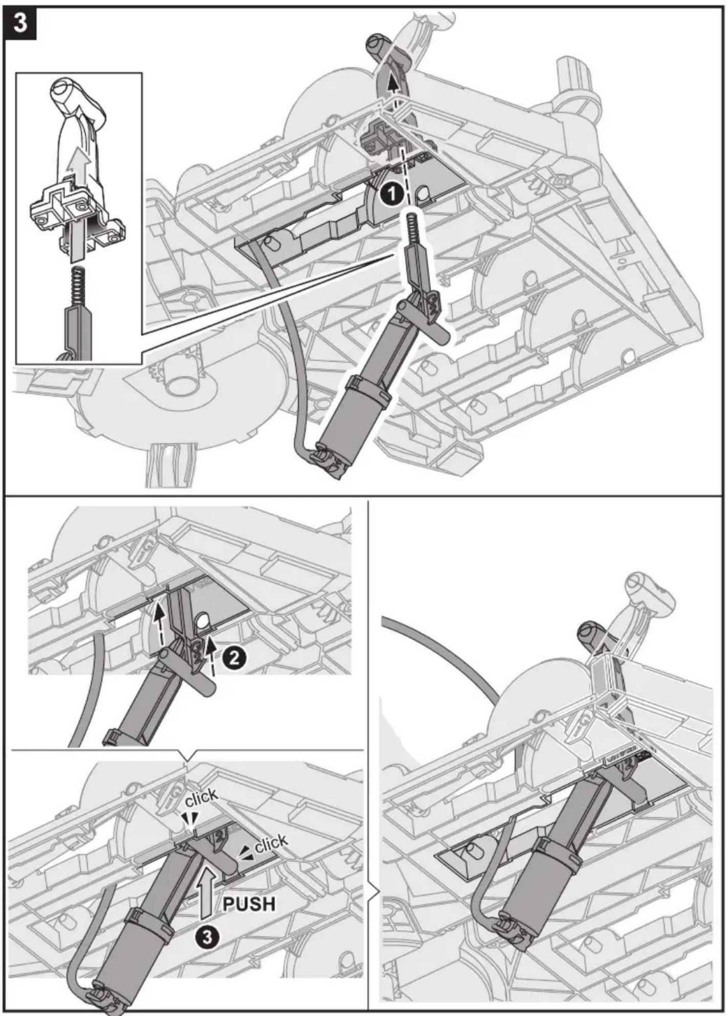
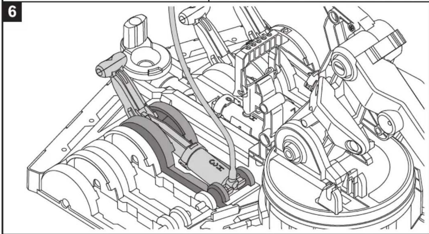
6
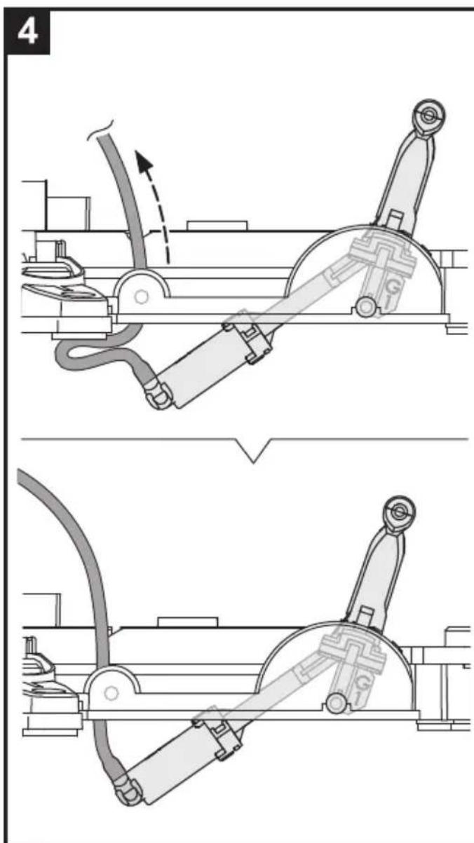
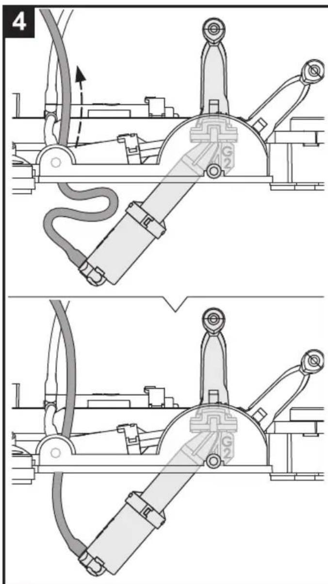
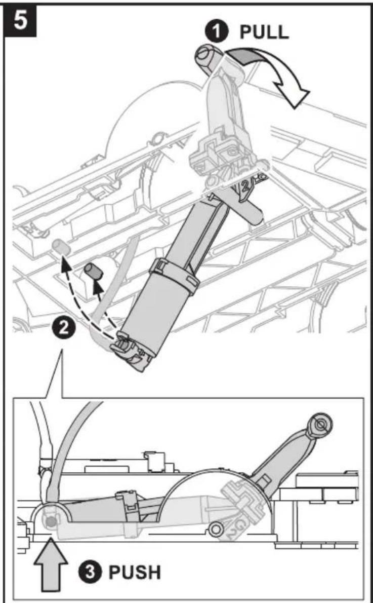
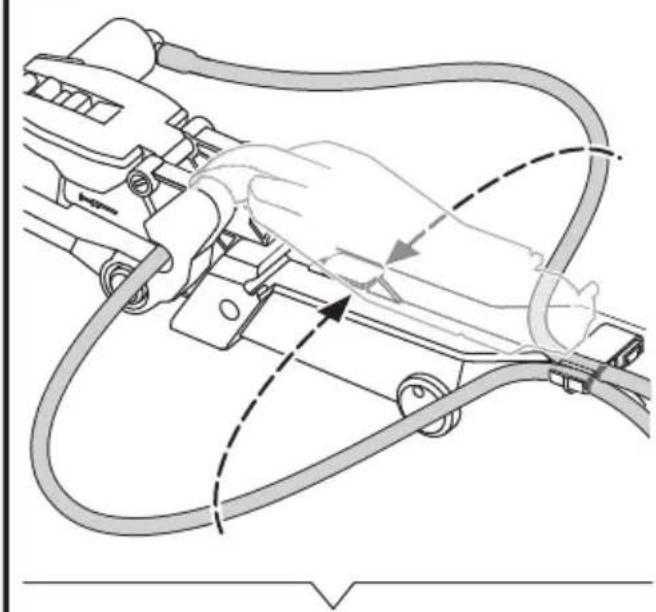
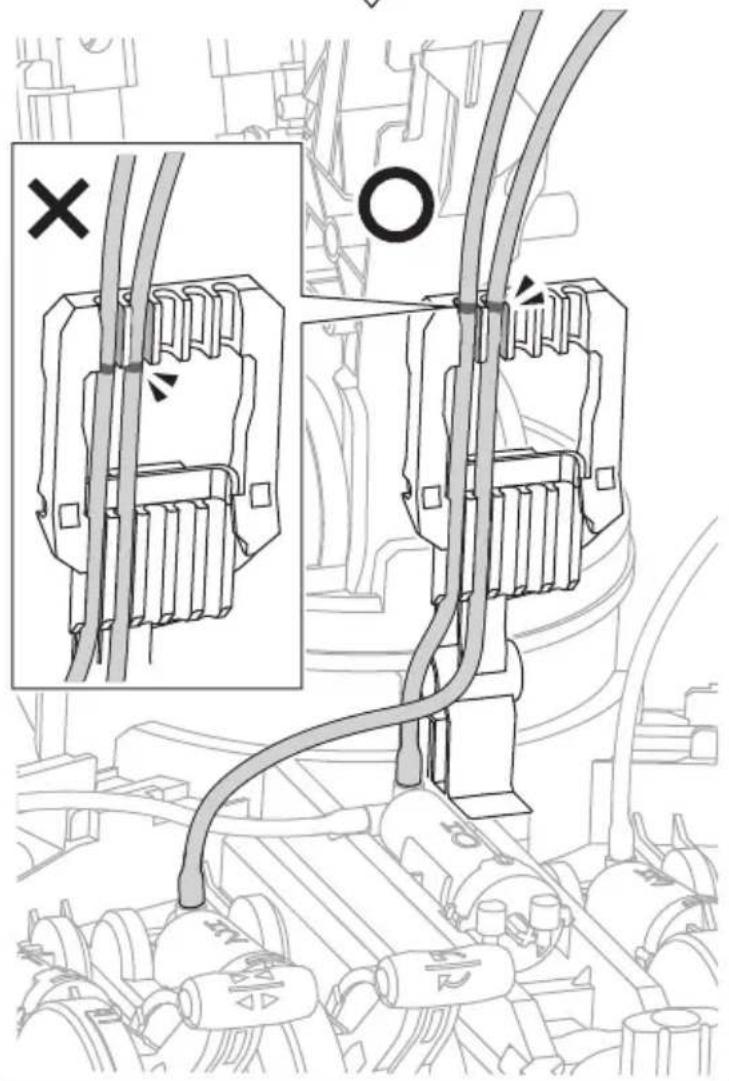
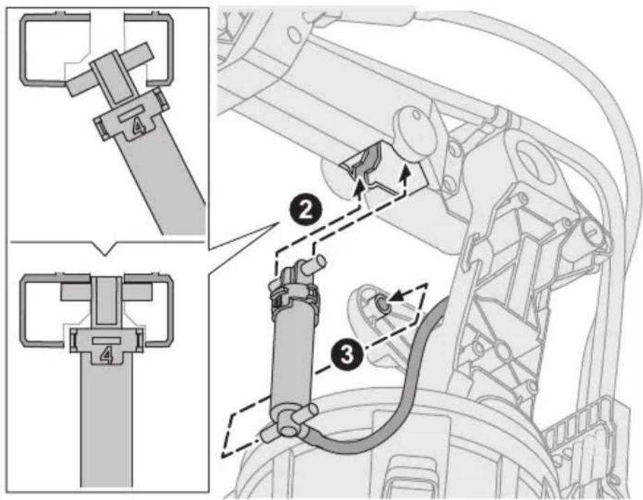
Set the soft tube in the groove.
natural_image
Technical diagram of a mechanical assembly with no visible text or symbols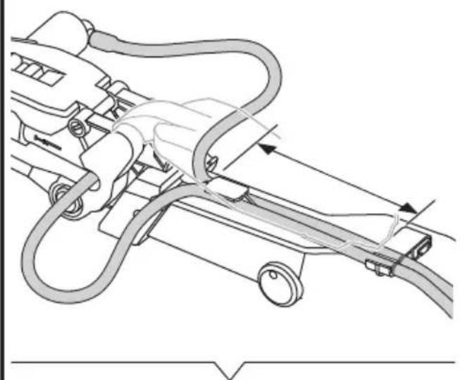
natural_image
Technical diagram of a mechanical assembly with hoses and connectors (no text or labels)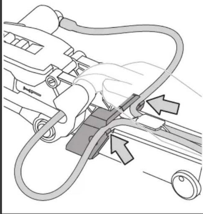
natural_image
Diagram of a car interior showing a hand connecting hoses to a vehicle, with arrows indicating cable or connector (no text or symbols present)7
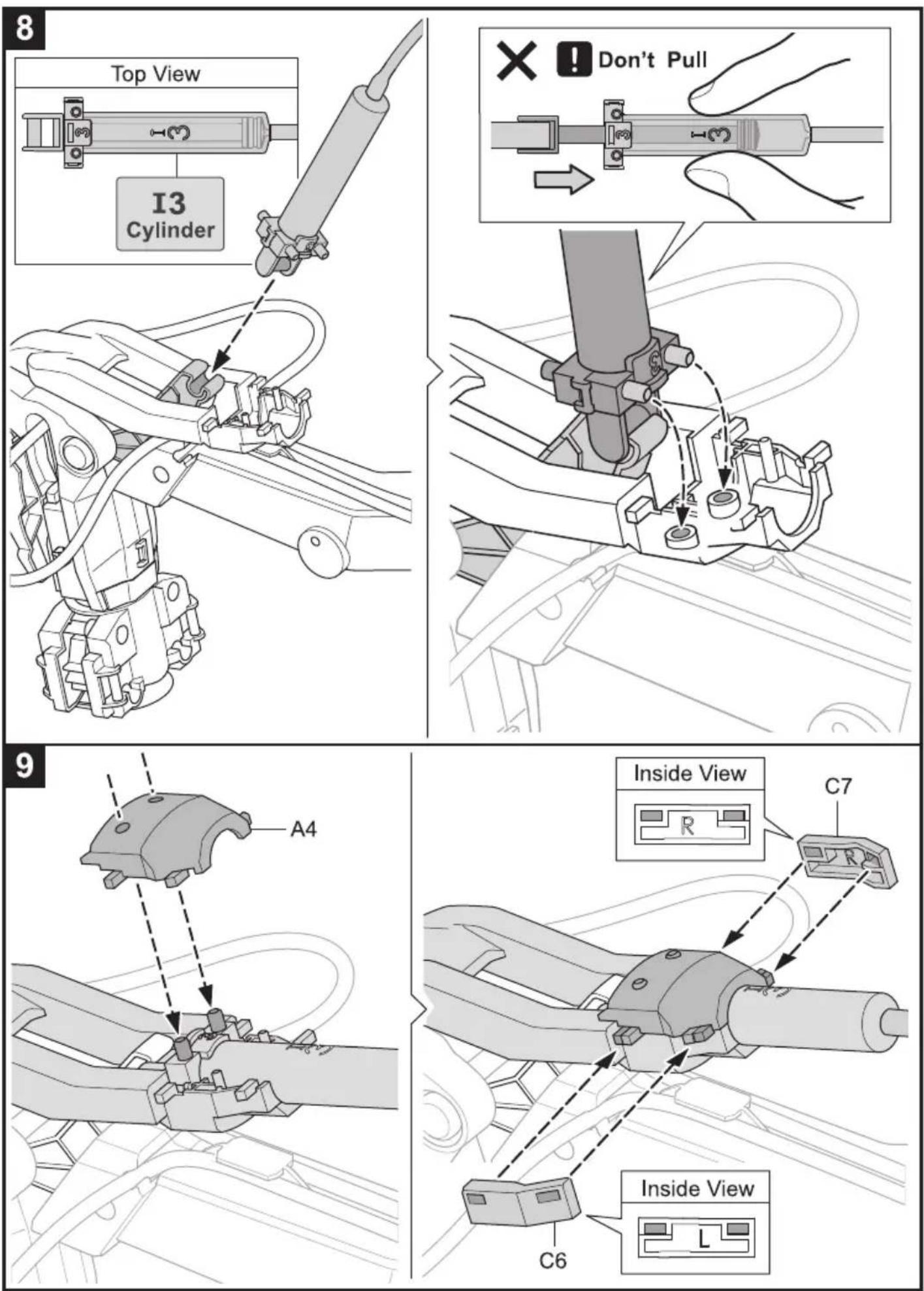
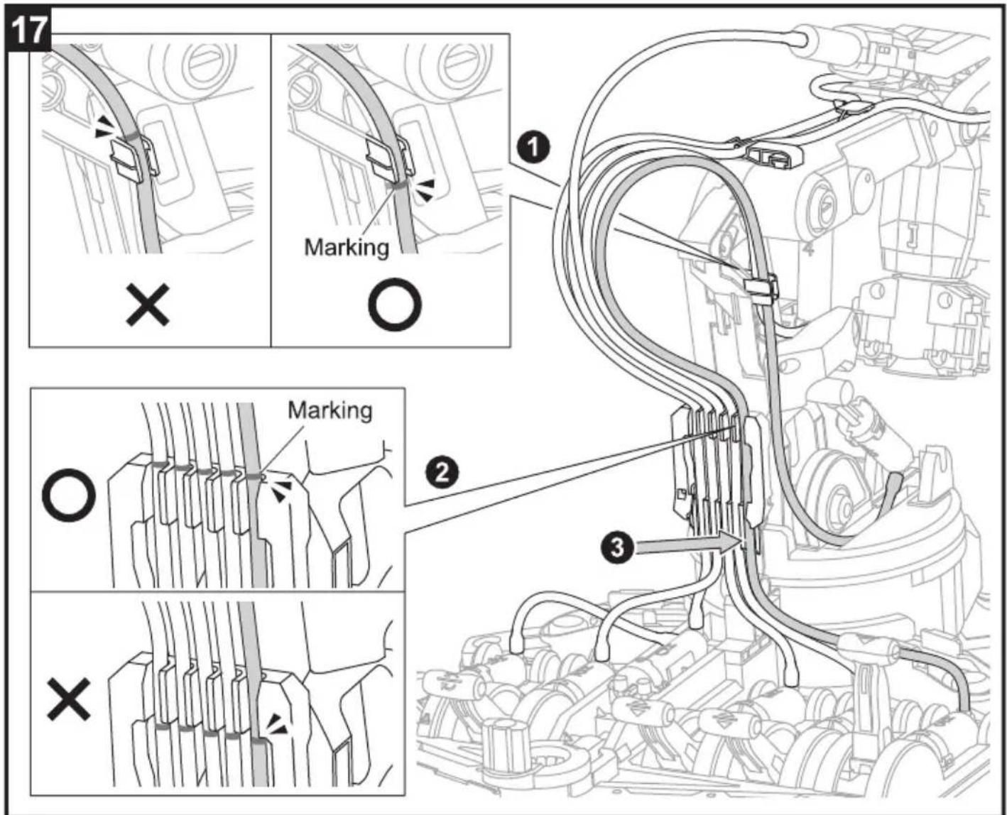
12 ① Ensure The Right Direction
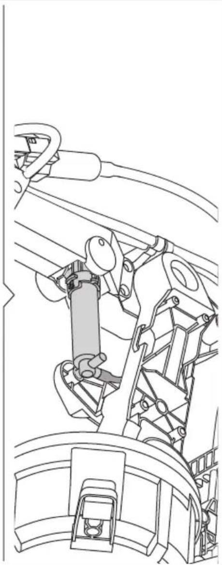
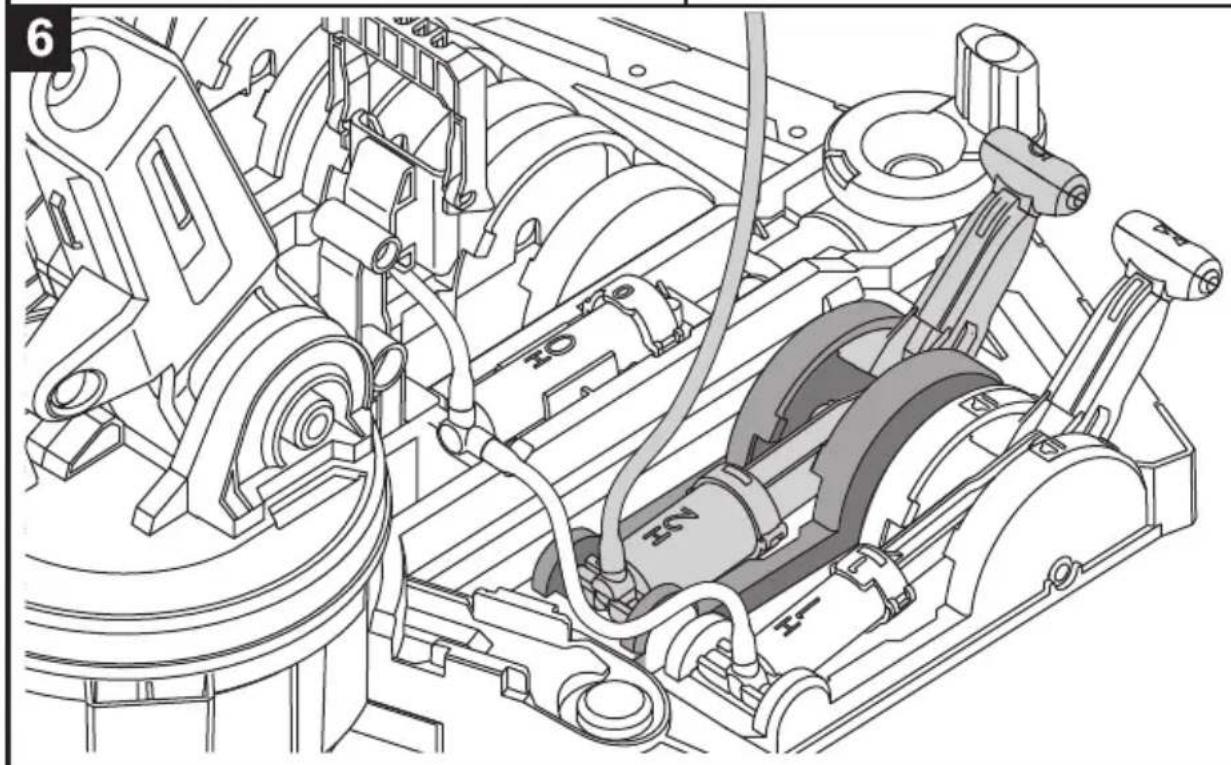
natural_image
Technical line drawing of a mechanical assembly with no visible text or symbols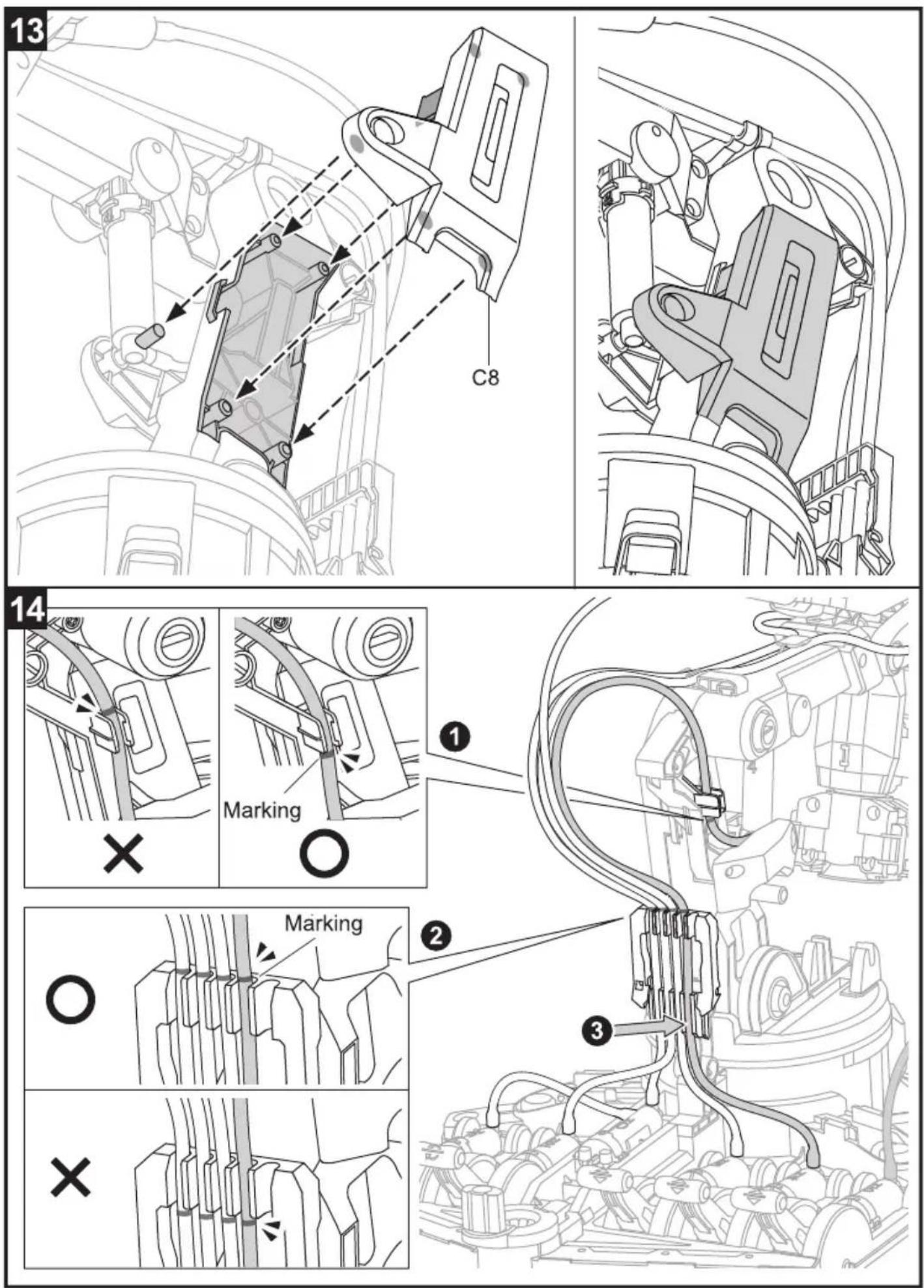
18
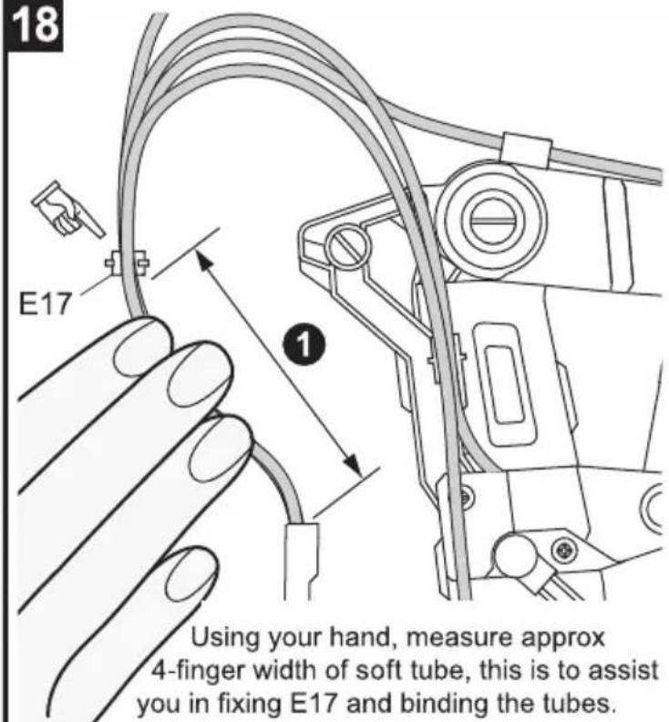
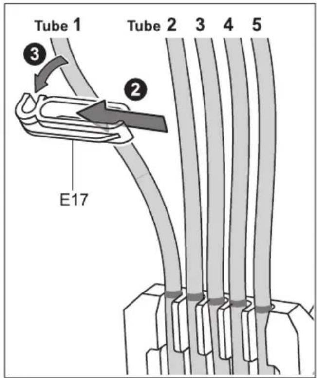
19
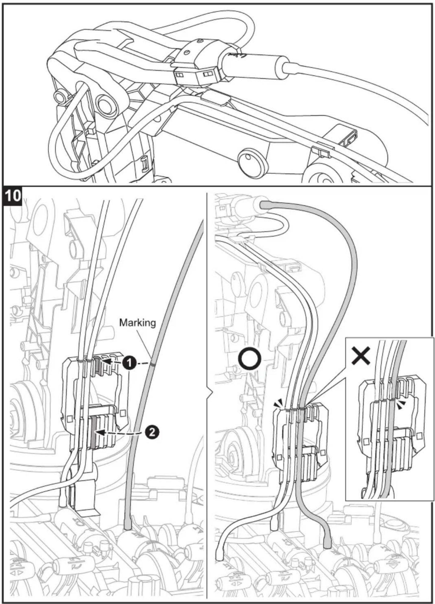
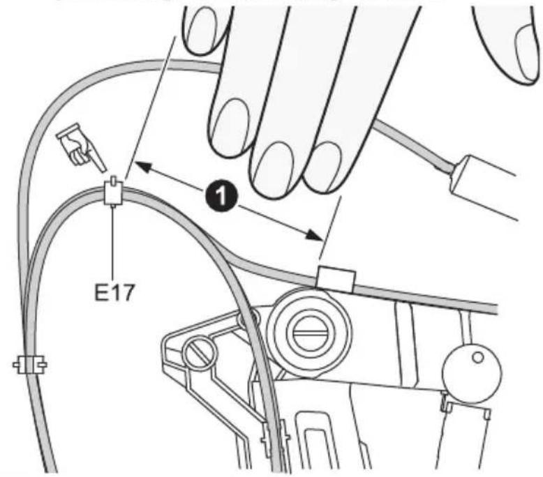
Using your hand, measure approx 4-finger width of soft tube, this is to assist you in fixing E17 and binding the tubes.
20
natural_image
Technical line drawing of a robotic arm with coiled cable and wiring, showing structural components without any text or symbols.How To Play
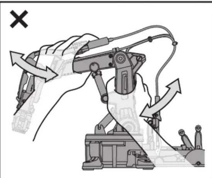
Warning
natural_image
Technical line drawing of a robotic arm with articulated joints and control panel (no text or symbols)
natural_image
Line drawing of a robotic arm with articulated joints and a cross symbol (no text or labels)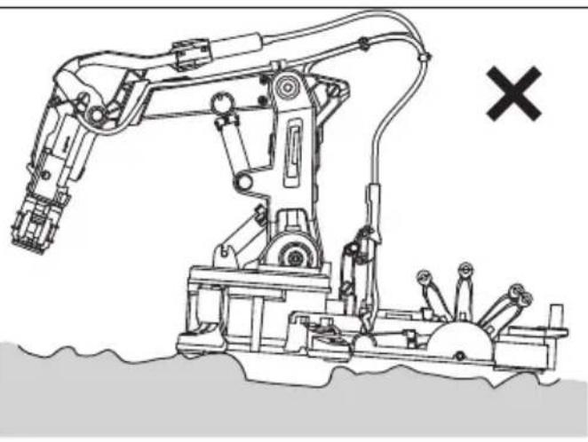
natural_image
Line drawing of a robotic arm with articulated joints and a cross symbol (no text or labels)Operate on a smooth and level surface.
natural_image
Illustration of a robotic arm with directional arrows indicating movement or force (no text or symbols present)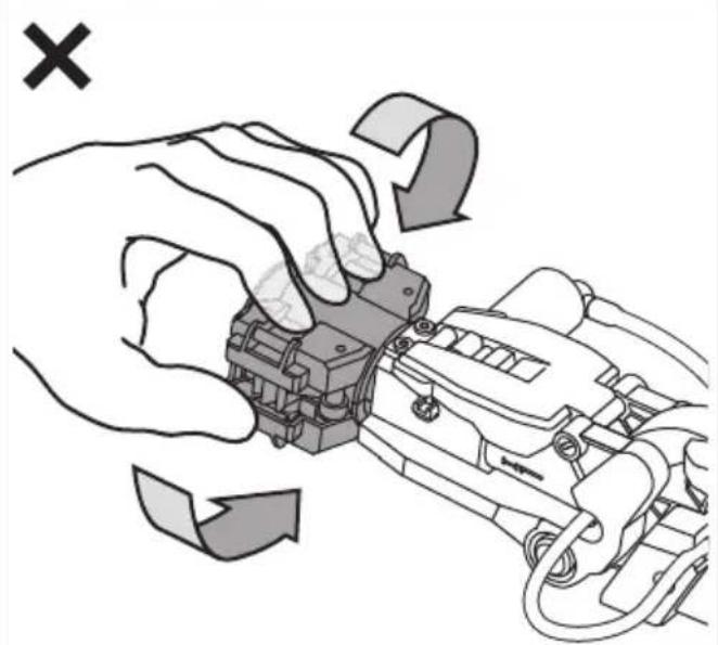
natural_image
Illustration of hands operating a mechanical device with directional arrows indicating motion (no text or symbols)Handle the arm with care and do not mistreat as shown above
How To Play: 2\~6 AXES
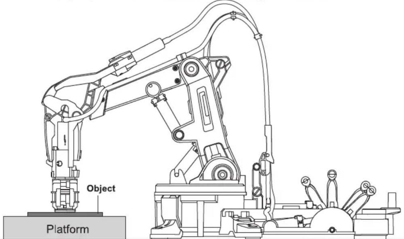
How To Play-Gripper Mode
1 Installation
2
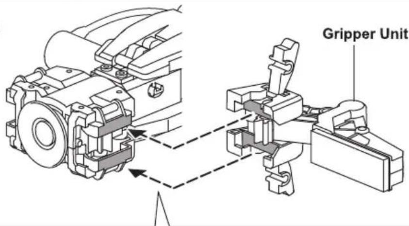
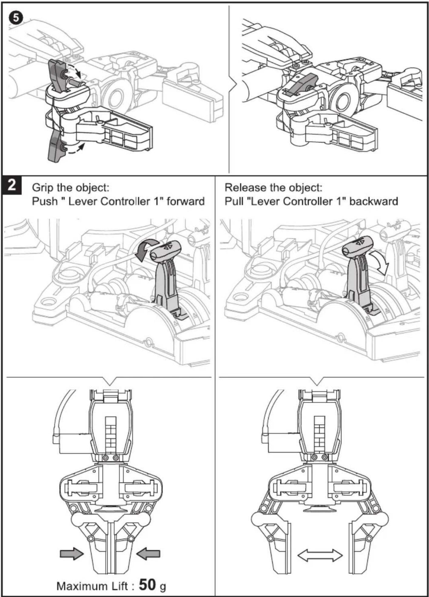
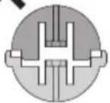
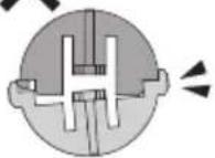
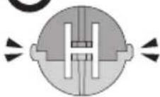
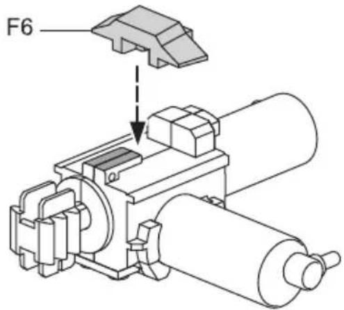
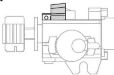
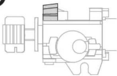
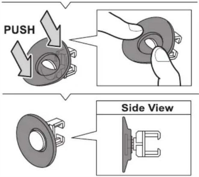
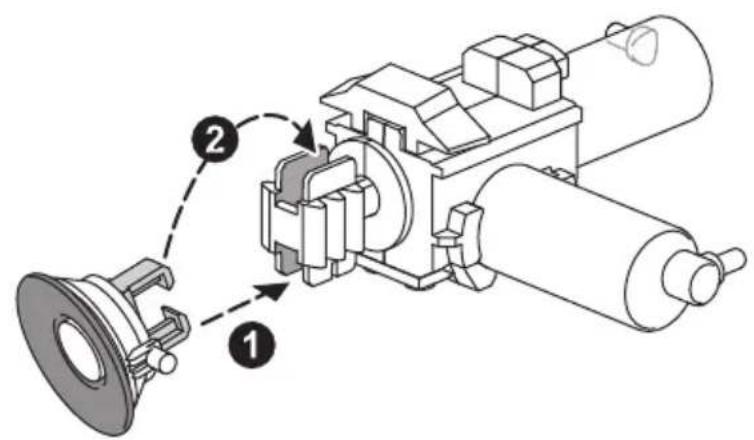
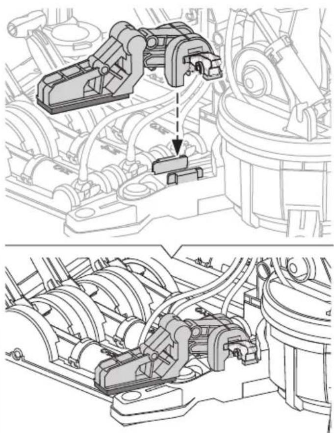
How To Play- Suction Mode
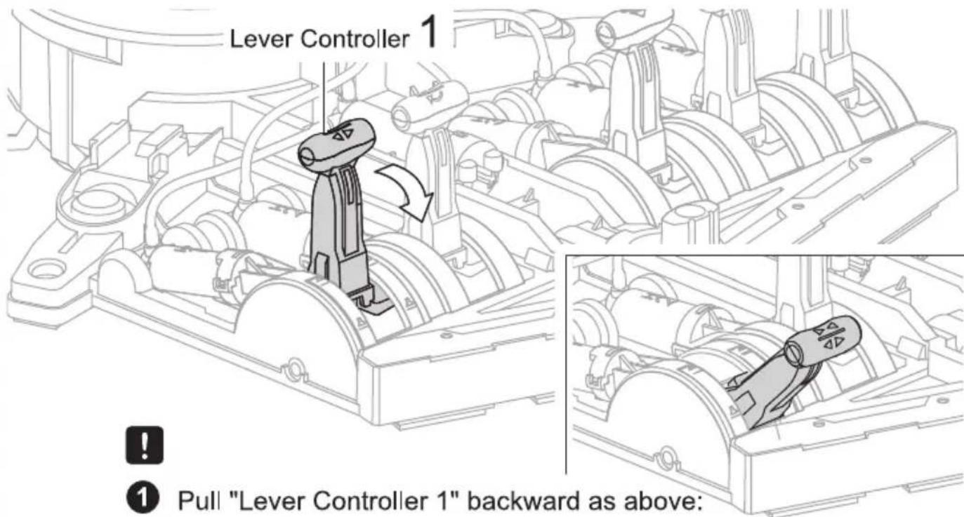
1 Release Gripper unit and put it aside as below
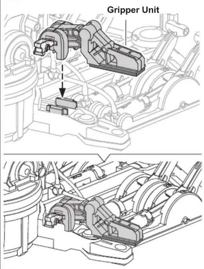
natural_image
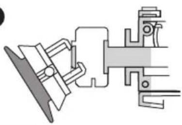
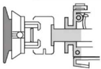
Technical line drawing of an engine assembly showing internal components and a close-up view (no text or labels)2 Very Important !! Step 2 must be completely fulfilled under Suction Mode.
natural_image
Technical line drawing of a mechanical assembly with no visible text or symbols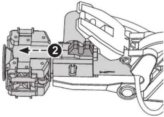
natural_image
Technical diagram of a mechanical assembly with labeled component (no text or symbols present)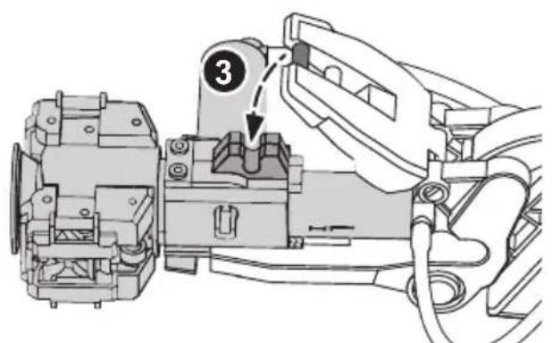
natural_image
Technical line drawing of a mechanical assembly with no visible text or symbols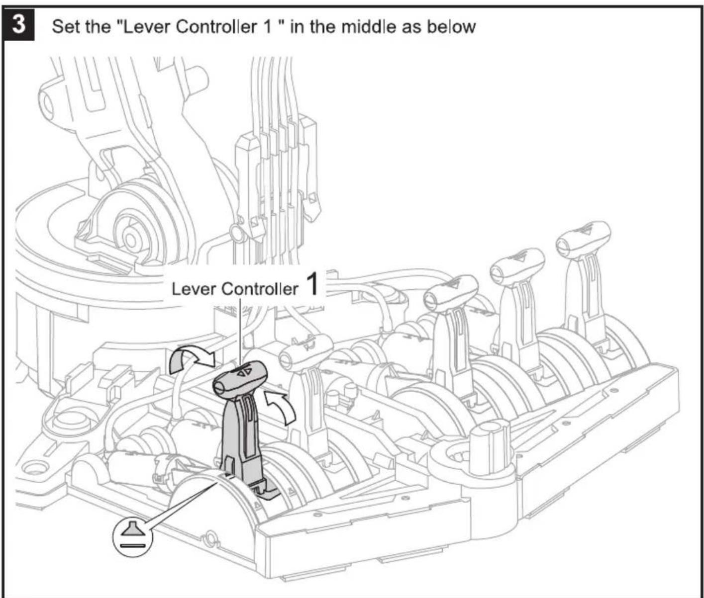
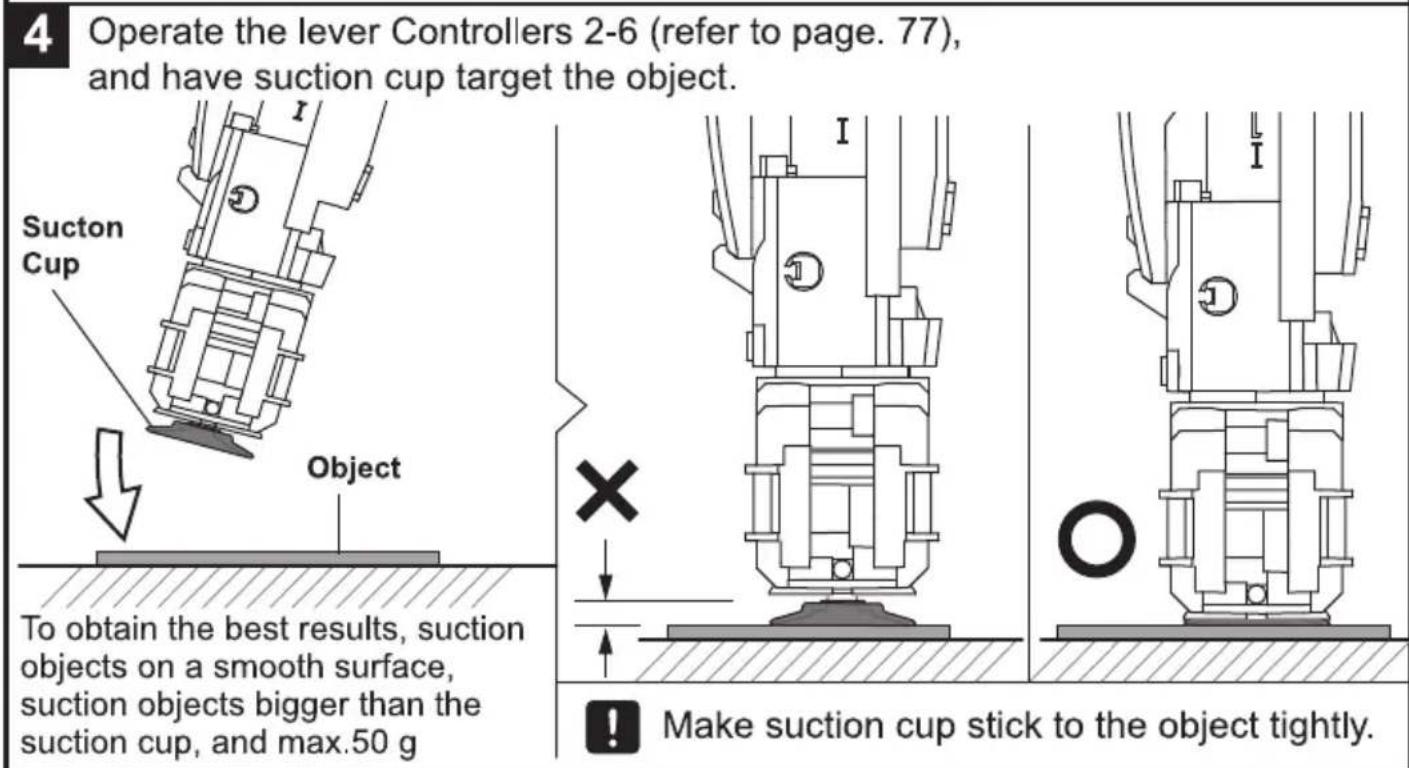
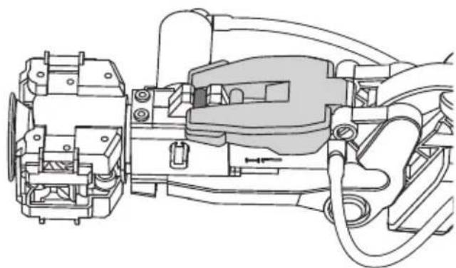
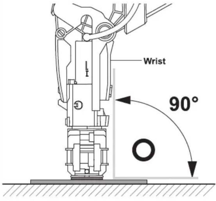
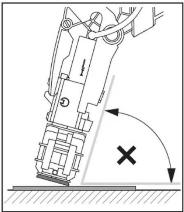
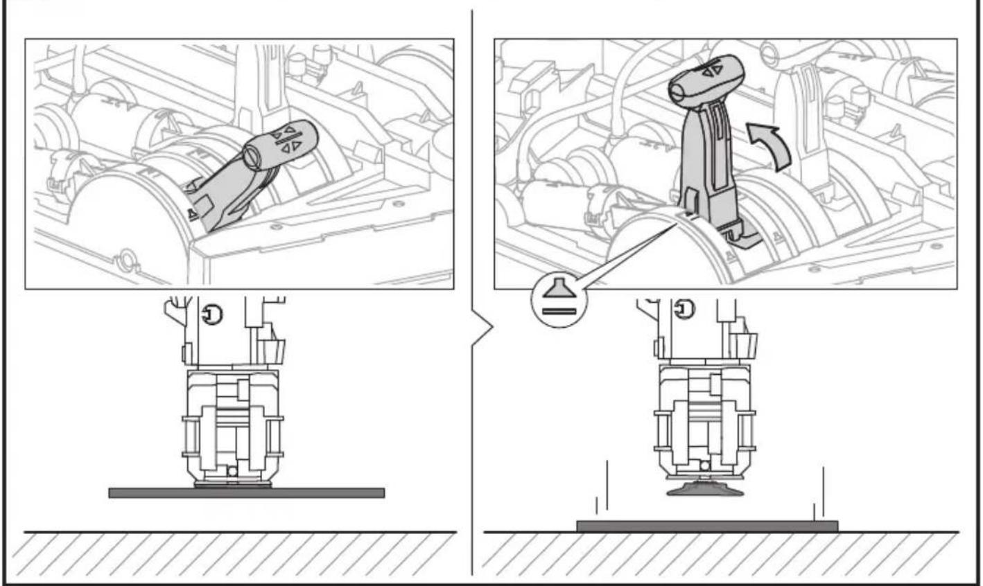
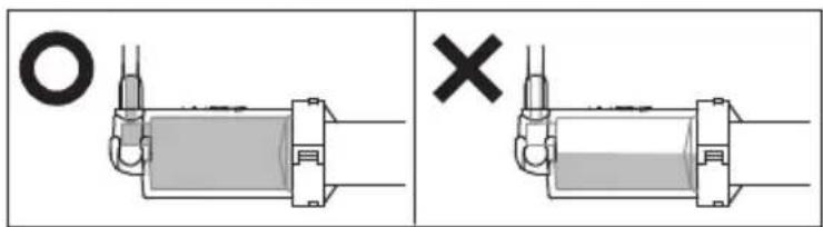
! Direct the Wrist to the object straightly
natural_image
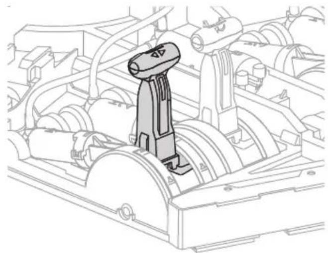
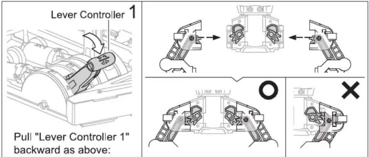
Mechanical robotic arm diagram showing force direction and collision mark (no text or symbols)5 Pull "Lever Controller 1" backward as below, and have the cup suck the object.
natural_image
Technical line drawing of a mechanical assembly with no visible text or symbols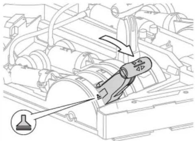
natural_image
Technical diagram of a mechanical assembly with directional arrows and a labeled component (no text or symbols present)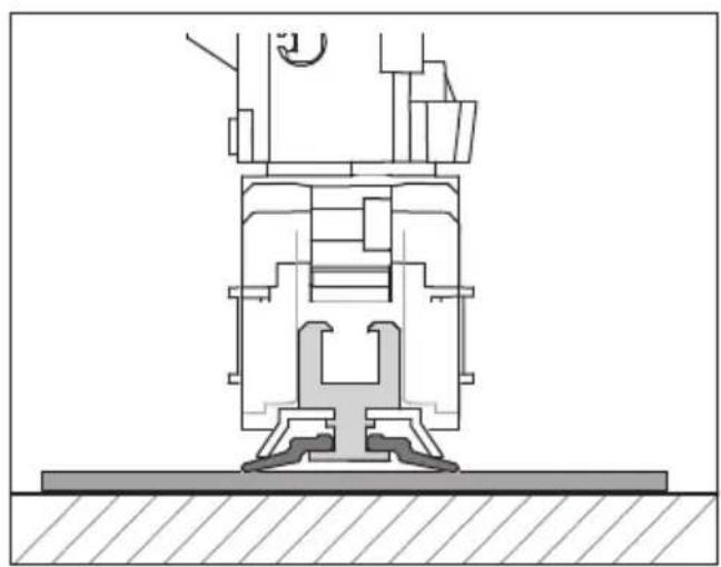
natural_image
Technical cross-sectional diagram of a mechanical assembly (no visible text or labels)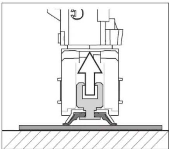
natural_image
Cross-sectional diagram of a mechanical assembly with no visible text or symbols6
Push "Lever Controller 5" forward to lift the object.
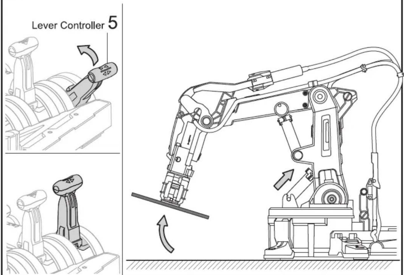
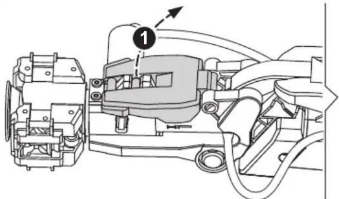
7
Set " Lever Controller 1" in the middle to release object.
8
Tip: Put the object under a slightly higher/and smoother platform, it may help you practice the "Suction mode" with greater success.
Trouble Shooting
- If gripper unit does not work (open or close) functionally, please check following steps.
- Check if gripper unit is installed in the correct position and direction (as below pics in pages 78,79)
- Back to page 32, and check step 16 is correct.
- Check if there is excess air inside the Cylinder H1, I1 and Tube 1. In the case, back to pages 42-45 to re-assemble."
- If sunction cup cannot suck the objects under suction mode.
- Back to pages 81\~84, and check if all steps 2\~6 are installed correctly.
- Check if there are excess air inside the Cylinder H1, I1 and Tube 1. In the case, back to pages 42-45 to re-assemble.
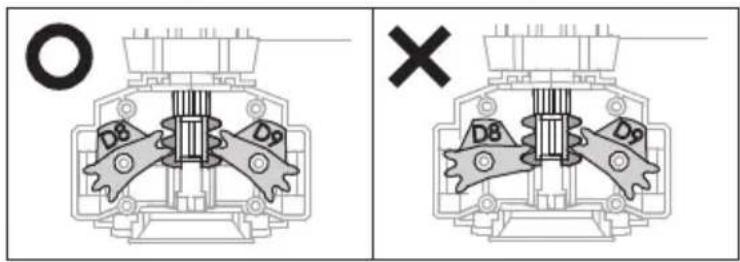
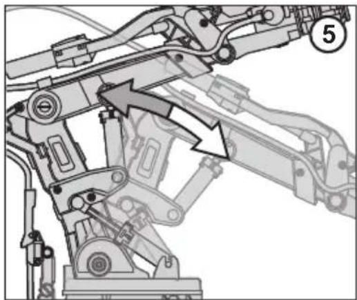
- If operation angle on the Axes 3/4/5 is unable to extend to the max.
natural_image
Mechanical assembly diagram showing linkage components with arrows indicating movement (no text or labels)- Check if there is excess air inside the Cylinder H3/4/5, I3/4/5, and Tube 3/4/5, in that case, back to pages 37\~40 to re-assemble.
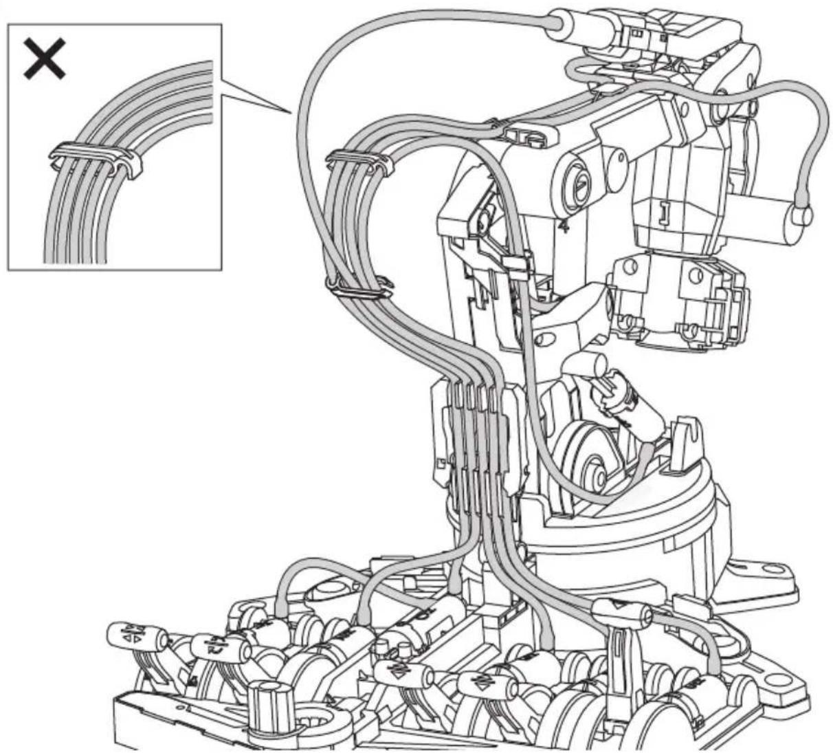
- Check if all tubes are routing and not twisting during assembly. In the case of twisted tubes.
(a) back to pages 66\~75 " Robot Arm Module Assembly " to check if all markings on the tubes are installed in the right position.
(b) back to Pages 46\~48 " Measuring & Marking " to check if all lengths of tubes are cut and marked correctly.
● Poor movement of the 6th Axe.
- If 6th Axe does not move when rotating E2, back to Page 19, Step 13 and check if E10 is intalled in the right position.
E10

- Check if all tubes are routing and not twisting during assembly. In the case of twisted tubes,
(a) back to pages 66\~75 "Robot Arm Module Assembly" to check if all markings on the tubes are installed in the right position.
(b) back to Pages 46\~48 " Measuring & Marking" to check if all lengths of tubes are cut and marked correctly.

CE

WARNING :
CHOKING HAZARD
Small parts
Not for children under
3 years


- HYDRAULIC ROBOTARM
- Contents
- Mechanical Assembly
- HYDRAULICROBOTARM
- Product Introduction
- Tools You May Need
- Mechanical Parts List
- Plastic Parts
- Gripper Unit Assembly
- Stand & Control Base Assembly
- Main Body Assembly
- How To Oil The Parts
- H0\~H5 Cylinder Assembly
- H1 Cylinder Assembly
- H2 Cylinder Assembly
- H3 Cylinder Assembly
- H4 Cylinder Assembly
- H5 Cylinder Assembly
- I1 \~ I5 Cylinder Assembly
- I1 & I2 Cylinder
- I5 Cylinder
- How To Cut The Tube
- How To Fill Up The Cylinder With Water
- Note
- Connect H4 With I4
- 1
- 2
- 3
- 4
- !
- Connect H3 With I3
- Connect H2 With I2
- Lever Controller Assembly
- Control Moduel Assembly
- Unit 2: H2 Cylinder & Lever Controller 2
- Unit 4: H4 Cylinder & Lever Controller 4
- How To Play
- How To Play-Gripper Mode
- Installation
- How To Play- Suction Mode
- Release Gripper unit and put it aside as below
- Very Important !! Step 2 must be completely fulfilled under Suction Mode.
- Trouble Shooting
- - If gripper unit does not work (open or close) functionally, please check following steps.
- - If sunction cup cannot suck the objects under suction mode.
Mærke : VELLEMAN
Model : KSR12
Kategori : Industribot