
RD-1000M - Kassettspelare ROTEL - Gratis bruksanvisning och manual
Hitta enhetens manual gratis RD-1000M ROTEL i PDF-format.

Användarfrågor om RD-1000M ROTEL
0 fråga om denna apparat. Svara på dem du kan eller ställ din egen.
Ställ en ny fråga om denna apparat
Ladda ner instruktionerna för din Kassettspelare i PDF-format gratis! Hitta din manual RD-1000M - ROTEL och ta tillbaka ditt elektroniska enhet i hand. På denna sida publiceras alla dokument som behövs för att använda din enhet. RD-1000M av märket ROTEL.
BRUKSANVISNING RD-1000M ROTEL
OWNER'S MANUAL


RD-1000m
WARNING: TO PREVENT FIRE OR SHOCK HAZARD, DO NOT EXPOSE THIS APPLIANCE TO RAIN OR MOISTURE.
Write your SERIAL NUMBER here.
The number is located near the name plate on
the unit's rear panel.

THE ROTEL CO., LTD.
1-36-B Ohokayama, Meguro-ku, Tokyo, Japan
INTRODUCTION
We at Rotel want to thank you for purchasing our audio product. Rotel audio products are designed to use the latest electronic technology, and they incorporate our long experience as a specialist manufacturer of audio equipment. We are confident that you will find satisfaction in the high quality sound and top performance, and that you will find pleasure in the functional beauty achieved through human-engineering concept.
Before starting operation, please read this instruction manual thoroughly and acquaint yourself with the proper mode of using the unit and all its connections.
We hope you will enjoy top-notch performance for many years to come.
POWER SUPPLY CONNECTION
For power the unit requires the normal house electrical current (AC). You may simply plug the unit to a wall outlet, or to your amplifier's (or receiver's) switched or unswitched AC outlet. If it is plugged to a switched outlet, by leaving the power switch of the unit on, you will be able to maintain switching control for the cassette deck with your amplifier or receiver. If it is connected to an unswitched outlet, like connecting to a wall outlet you must use the cassette's own power switch for switching control.
CAUTION - Do not apply power without first making sure the proper connections are completed. If you live in U.K. and your unit comes with 2-core cord without a plug, be sure to read the exclusive caution for U.K.
INSTALLATION
Be sure to place the unit in a level and flat place where it is free from humidity, vibration, high temperature and not exposed to direct sunlight.
Be careful not to place the unit in a highly enclosed place such as near a wall or on a bookshelf. A poor ventilation will cause undesirable effects to the unit.
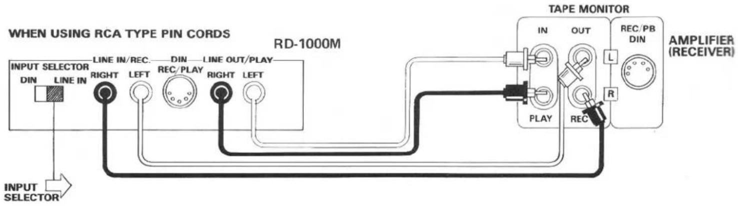
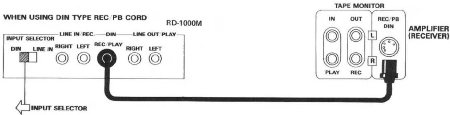
CONNECTION TO RE- CEIVER OR AMPLIFIER
Connect the unit's rear panel terminals to the TAPE MONITOR terminals of your amplifier, using either the RCA cords or a single DIN type record/playback cord. The unit's LINE IN terminals should be connected to the TAPE MONITOR OUT terminals of the amplifier, and the LINE OUT terminals to the TAPE MONITOR IN terminals of the amplifier. Be certain to properly match right and left terminals between components. Do not attempt to connect the RCA type cords when the DIN type record/playback cord is used.
Note: Set the input selector switch at the left position when DIN cord is used, and at the right position when RCA cord is used.
EXCLUSIVE NOTE FOR U.K.
If your unit comes with a 2-core cable without a plug, make certain live and neutral leads are connected to the proper terminals. Check that the terminals are screwed down firmly and no loose strands of wire are present.
IMPORTANT: The wires in this mains lead are coloured in accordance with the following code:
BLUE: NEUTRAL BROWN: LIVE
As the colours of the wires in the mains lead of this apparatus may not correspond with the coloured markings identifying the terminals in your plug proceed as follows.
The wire which is coloured BLUE must be connected to the terminal which is marked with the letter N or coloured BLUE or BLACK. The wire which is coloured BROWN must be connected to the terminal which is marked with the letter L or coloured BROWN or RED.
flowchart
graph TD
    A["INPUT SELECTOR"] --> B["LINE IN"]
    B --> C["RIGHT"]
    C --> D["LINE IN/REC."]
    D --> E["LEFT"]
    E --> F["DIN"]
    F --> G["REC/PLAY"]
    G --> H["RIGHT"]
    H --> I["LINE OUT/PLAY"]
    I --> J["LEFT"]
    J --> K["RD-1000M"]
    K --> L["TAPE MONITOR"]
    L --> M["IN"]
    L --> N["OUT"]
    L --> O["REC/PB DIN"]
    L --> P["R"]
    P --> Q["RECEIVER"]
    style A fill:#f9f,stroke:#333
    style L fill:#ccf,stroke:#333
    style P fill:#cfc,stroke:#333
MICROPHONE AND HEADPHONE CONNECTION
Microphones and headphones may be connected to the unit using the respective jacks on the front panel. When using stereo microphones, be sure connections are made properly to the left and right jacks.
NOTE: Microphones must not be connected except when carrying out microphone recording.
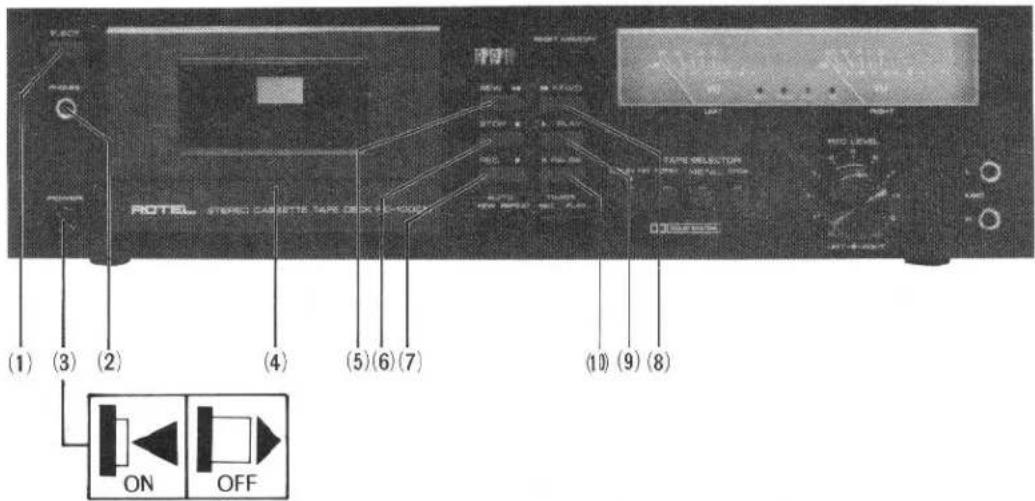
CONTROL FUNCTIONS
(1)
EJECT BUTTON
This button is used for placing cassette tapes in the deck or for removing tapes. When the button is pressed, the cassette door will open for placement or removal of the tape. The cassette door can then be closed manually.
(2)
Phones Jack
You may connect a pair of headphones to this jack for private listening.
(3)
Power Switch
Performs the function as its name denotes. It supplies power to the unit and to any switched AC outlets. When the switch is ON the cassette holder light will be illuminated.
(4)
Cassette Trap Door
Depress the EJECT button to open the door, and push lightly with your fingers to close the door.
(5)
Rewind Button (◀◀)
Depress this button to rapidly return the tape in the direction of the arrows. To protect the tape, this function will automatically disengage when the tape is fully wound onto the supply reel.
(6)
STOP BUTTON (■)
This butotn is used to stop operations and take the unit out of the recording, playback, rewind or fast-forward.
(7)
Record Button (●)
Allows you to activate the record mechanism and must be depressed simultaneously with the PLAY button in order to start the tape in motion when recording.
(8)
Fast Forward Button (▶▶)
Depress this button to rapidly advance the tape in the direction of the arrows. To protect the tape, this function will automatically disengage when the tape is fully wound onto the take-up reel.
but
with the RECO
autostop mechanism with automatically disengage the button once the tape is fully taken up by the take-up reel.
(10)
Pause Button (Ⅲ)
Used in conjunction with the PLAY or RECORD button. When depressed, this button will interrupt the motion of the tape while playing or recording without affecting the position of the PLAY or RECORD button. Push again to release. Note the PAUSE button will not be released by the STOP button.
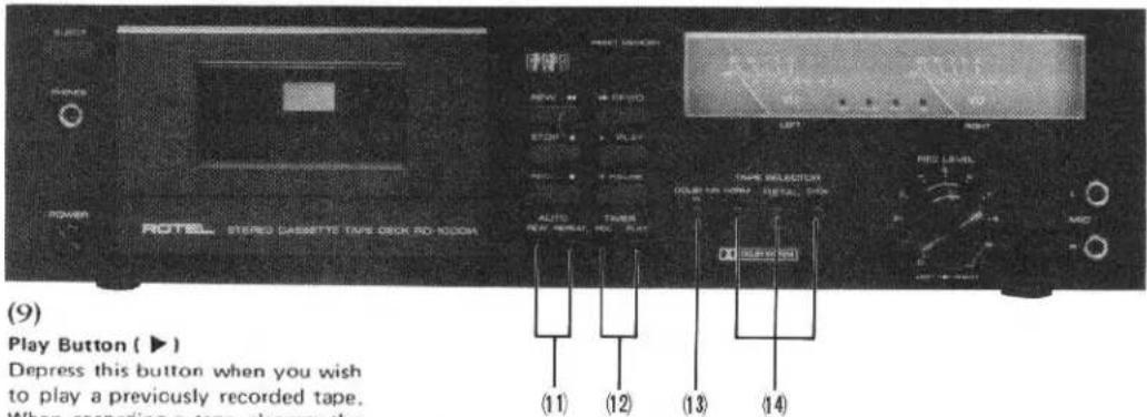
(11)
AUTO REWIND/REPEAT
SWITCH
When the automatic rewind switch (AUTO REW) is pressed, if the MEMORY switch is also depressed at the time, the tape will automatically rewind to counter indication 999 when the recording or playing is completed and the tape ends, and the tape will then stop. If the MEMORY switch is not depressed, the cassette tape will be rewound to its beginning and will stop. When the automatic repeat switch (AUTO REPEAT) is pressed, if the MEMORY switch is depressed at the time, the tape will automatically rewind to counter indication 999 when the recording or playing is completed and the tape ends, and the tape will then repeat from that point. If the MEMORY switch is not depressed, the cassette tape will be rewound to its beginning and will repeat from the start.
(12)
TIMER RECORDING/PLAYING SWITCH
When you wish to use the timer for recording, press the timer recording switch (TIMER REC). Likewise, when you wish to use the timer for playing back recordings, press the timer playing switch (TIMER PLAY).
(13)
Dolby NR Switch
To record or play back through the built-in Dolby noise reduction circuit be sure to set the DOLBY NR switch to ON beforehand. The DOLBY lamp will glow to indicate that the Dolby circuit is in operation. Any tape recorded through the Dolby circuit should also be played back through the Dolby circuit for optimum results.
(14)
TAPE SELECTOR SWITCHES
The unit can be adjusted according to the type of cassette tape being used.
[NORMAL] should be pressed when standard cassette tapes are being used.
[METAL] is used for metal tapes. [CrO_2] should be pressed if the tape in use is a chromium dioxide tape.
For further details, see the separate table.
(15)
Rec Level Control
Allows you to control the recording level of incoming signals, such as from turntable, tuner and microphones.
The separate left and right channel controls are provided for reliable adjustment.
(16)
Microphone Jacks
Use only low impedance type microphones (around 600 ohms). The microphones should be plugged only for a live recording, so if you are recording other sources be sure to remove the microphones from the jacks.
(17)
Tape Counter
The three-digit tape counter is provided as a means of relocating any given point on a tape once it has been recorded. When a recording is being made, simply log the reading on the counter at the beginning of each selection. You will then be able to wind the tape to the same point at any future date.
(18)
Reset Button
The RESET button allows you to reset the counter to zero so that you will always be able to use the same frame of reference.
TAPE SELECTOR SETTING GUIDE
| メーカー | ブランド | 種類 | PUSH THIS BUTTON OF TAPE SELECTOR SWITCHES | ||
| MANUFACTURER | BRAND | TYPE | NORM | METAL | CrO2 |
| MAXELL | UL | NORMAL | ● | ||
| UD | NORMAL | ● | |||
| MX | METAL | ● | |||
| TDK | OD | NORMAL | ● | ||
| AD | NORMAL | ● | |||
| O | NORMAL | ● | |||
| MA | METAL | ● | |||
| SONY | AHF | NORMAL | ● | ||
| BHF | NORMAL | ● | |||
| CHF | NORMAL | ● | |||
| METALLIC | METAL | ● | |||
| JHF | CrO2 | ● | |||
| BASF | LH | NORMAL | ● | ||
| SLH-1 | NORMAL | ● | |||
| SCR | CrO2 | ● | |||
| PHILIPS | CHROM | CrO2 | ● | ||
| FUJI | RANGE-2 | NORMAL | ● | ||
| RANGE-4 | NORMAL | ● | |||
| RANGE-6 | NORMAL | ● | |||
| SUPER RANGE | METAL | ● | |||
| RANGE-4X | CrO2 | ● | |||
| SCOTCH | MASTER 120μS | NORMAL | ● | ||
| CRYSTAL | NORMAL | ● | |||
| METAFINE | METAL | ● | |||
| MASTER 7μS | CrO2 | ● | |||
| AMPEX | PLUS | NORMAL | ● | ||
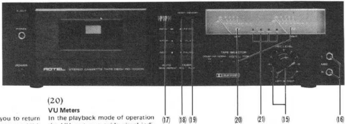
(19)
Memory Button
This function allows you to return the tape to a point you establish anywhere along the tape. Choose a position on the tape during recording or playback and depress the MEMORY button, and then press the RESET button to 000 to establish that position as the starting point. Thereafter, when the REWIND button is depressed, the tape will automatically stop just pass that position, at 999 on the tape counter. This function is convenient to cue a program you wish to hear repeatedly. It is also possible when recording to leave a blank portion in the tape and then later return precisely to that point for re-recording or ad-lib. Press the MEMORY button again to cancel this function.
(20)
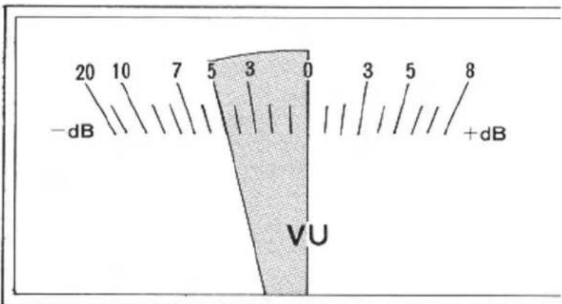
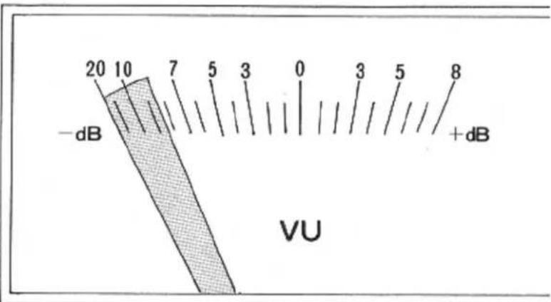
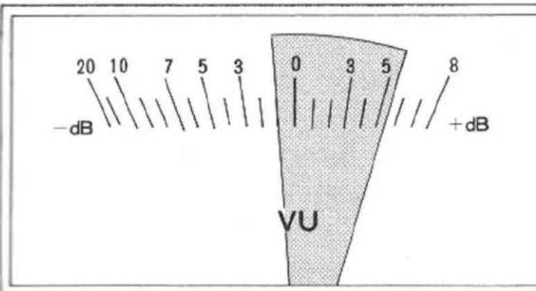
VU Meters
In the playback mode of operation the VU meters provide visual indication of the signal being fed. In the record mode the VU meters are used to monitor the level of the signal being recorded on the tape. They should be used along with the REC LEVEL controls to maintain the proper recording level.
(21)
INDICATORS
[REC]This indicator will come on when the unit is in the recording mode.
[PAUSE] This will come on when the PAUSE function is being used.
[PEAK] This indicator will come on to indicate excess input in the recording level. When it winks rapidly, it indicates a definite over-level condition, and the recording level control (REC LEVEL) should be turned to the left. If it lights up only from time to time, the recording is at an appropriate level.
[ ] This indicator lights up during Dolby recording or playback.
AUTOMATIC SHUTOFF SYSTEM
To protect the RD-1000M's motor and drive mechanism against unnecessary wear, an automatic shut-off device has been built into the machine. When the supply hub stops for any reason the motor and drive mechanism will automatically shutoff after a short period of time (usually about 5 seconds). The machine is also automatically shutoff at the end of tape (PLAY, REC/PLAY, FAST FORWARD and REWIND modes), disengaging all locked buttons.
NOTE — Since this device will not affect the electronic circuits of the machine it will still be necessary to turn off the entire unit by pushing the power switch.
CASETTE TAPES
High-performance tapes ranging from normal to metal types are suitable for this component. In addition, tape, tension and capstan tolerance for this unit have been carefully adjusted to the specific tape thickness of C30, C60 and C90 cassettes. For this reason, the use of C120 cassettes is not recommended. As cleanliness and precision are necessary for accurate sound reproduction, cassettes should always be handled with care, and kept away from dust and magnetic influences which might cause sound distortion.
Cassette tapes are provided with a safety feature which prevents against accidental erasure of previously recorded material. This feature consists of two small tabs located on both sides at the rear of the cassette housing. After a recording has been made, these tabs are removed, leaving two small, square openings which prevent further recording on that tape. (You will notice that these tabs are absent on any pre-recorded tapes you may have.) If you wish to guard against erasure on a recording you have made on a blank cassette, it is necessary to remove one or both of these tabs as follows:
-
If both sides have been recorded, insert a thin bladed screwdriver in the opening around each tab and gently pry the tab off. Be sure the tab falls free from the cassette.
-
If one side only has been recorded, place the cassette on a table just as it has been removed from the recorder, with the side recorded facing up and the exposed tape area facing you. You should then remove the tab in the left-hand corner to prevent erasure of that
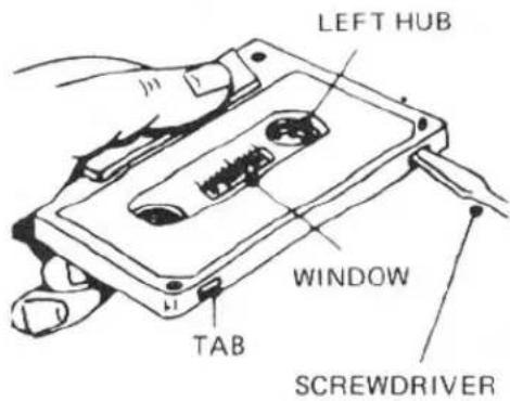
natural_image
Line drawing of hands operating a cassette tape with a screwdriver (no text or symbols)side of the tape.
If you later wish to record over a previously recorded tape, simply place a piece of adhesive tape over the tab opening. This will allow you to make a new recording. Removal of the tape after recording will again insure against accidental erasure.
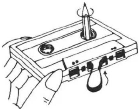
The cassette tape, when wound loosely on either hub, is likely to jam around the capstan and pinch roller during recording or playback. Therefore, if the tape is loose, insert a pencil into the more tightly wound hub, and turn it with the pencil until the slack is taken up. Always be sure to check that the tape is wound tightly before inserting a cassette in your deck.
BEFORE RECORDING OR PLAYBACK/CASSETTE INSERTION
-
Be certain that the power connection, and connections between the various components are properly made.
-
Make sure that the erasure prevention tabs at the rear of the cassette you plan to use are present, or that you have placed a piece of tape over the openings if the tabs are missing.
-
If you are recording with microphones, be sure they are properly inserted in the MIC jacks.
-
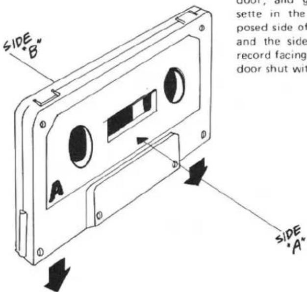
To insert a cassette, press the EJECT button to open the cassette door, and gently insert the cassette in the holder, with the exposed side of the tape facing down and the side you wish to hear or record facing you. Press the cassette door shut with your fingers.
RECORDING
- When recording with microphones, be sure that the microphone plugs are properly inserted into the left and right MIC jacks.
-
When recording from LINE sources, choose the appropriate program (tuner, turntable, etc.) on your amplifier.
-
When you wish to record using the Dolby NR circuit, set the DOLBY SWITCH to the ON position.
- Set the TAPE SELECTOR switches to match the type of tape used.
- Turn the POWER SWITCH to ON.
- Depress the PAUSE button.
- Simultaneously depress the REC and PLAY buttons.
-
Adjust the recording level. Using the two VU meters, adjust the left and right REC LEVEL controls so that the farthest position reached by the VU indicators does not exceed 0dB. (See Diagram)
-
After adjusting recording levels, you may begin recording by again depressing the PAUSE button to start the tape.
- Be certain to occasionally check the VU meters during recording. If the PEAK INDICATOR lamp goes on frequently, the power input should be decreased slightly. The PAUSE button may be depressed if you wish to momentarily halt recording.
- When you have completed a recording, press the STOP button. When the tape becomes fully wound onto the take-up spool, it will stop automatically.
Optinal Input
Inadequate Input (Increase recording revel) (Turn REC LEVEL control to right.)
Excessive Input (Decrease recording level.) (Turn REC LEVEL control to left)
PLAYBACK
-
When using Dolbyized tapes, set the DOLBY NR switch to ON.
-
Set the TAPE SELECTOR switches to match the type of tape used.
-
Turn the power switch on your amplifier to ON, with the volume control set to the minimum position. (When using headphones connected to the tape deck, there is no need to use the amplifier for playback).
-
Turn the POWER switch to ON.
- Press the PLAY button to begin playback.
-
Adjust the volume to your desired volume level.
-
To momentarily halt playback, press the PAUSE button. When you wish to end playback, press the STOP button. When the tape becomes fully wound onto the take-up spool, it will stop automatically.
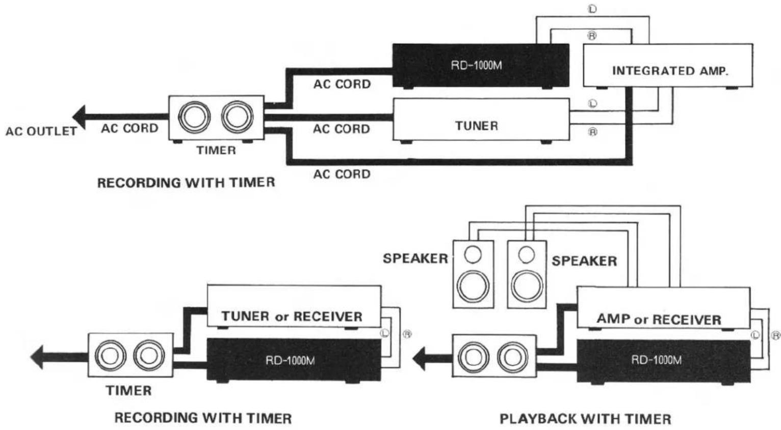
HOW TO OPERATE THE UNIT WITH TIMER
A. Recording with timer
-
Plug the timer into a wall outlet, and connect the cassette deck and related components (receiver, tuner, etc.) to the timer following the instructions provided with it.
-
Insert a cassette into the holder.
-
Turn on the cassette deck and related components (tuner, etc.).
-
Depress PAUSE button, and set the unit at record mode. Maintaining this state, adjust recording level and tune in the audio source (tuner, etc.)
-
Depress TIMER REC button.
-
Release PAUSE button.
-
Preset the timer to the desired time to activate the system, following the instructions provided with it.
- The unit will begin recording at the preset time.
flowchart
graph LR
    subgraph Recording With Timer
        A["AC OUTLET"] --> B["AC CORD"]
        B --> C["TIMER"]
        C --> D["AC CORD"]
        D --> E["AC CORD"]
        E --> F["AC CORD"]
        F --> G["AC CORD"]
        G --> H["AC CORD"]
        H --> I["AC CORD"]
        I --> J["AC CORD"]
        J --> K["AC CORD"]
        K --> L["AC CORD"]
        L --> M["AC CORD"]
        M --> N["AC CORD"]
        N --> O["AC CORD"]
        O --> P["AC CORD"]
        P --> Q["AC CORD"]
        Q --> R["AC CORD"]
        R --> S["AC CORD"]
        S --> T["AC CORD"]
        T --> U["AC CORD"]
        U --> V["AC CORD"]
        V --> W["AC CORD"]
        W --> X["AC CORD"]
        X --> Y["AC CORD"]
        Y --> Z["AC CORD"]
        Z --> AA["AC CORD"]
        AA --> AB["AC CORD"]
        AB --> AC["AC CORD"]
        AC --> AD["AC CORD"]
        AD --> AE["AC CORD"]
        AE --> AF["AC CORD"]
        AF --> AG["AC CORD"]
        AG --> AH["AC CORD"]
        AH --> AI["AC CORD"]
        AI --> AJ["AC CORD"]
        AJ --> AK["AC CORD"]
        AK --> AL["AC CORD"]
        AL --> AM["AC CORD"]
        AM --> AN["AC CORD"]
        AN --> AO["AC CORD"]
        AO --> AP["AC CORD"]
        AP --> AQ["AC CORD"]
        AQ --> AR["AC CORD"]
        AR --> AS["AC CORD"]
        AS --> AT["AC CORD"]
        AT --> AU["AC CORD"]
        AU --> AV["AC CORD"]
        AV --> AW["AC CORD"]
        AW --> AX["AC CORD"]
        AX --> AY["AC CORD"]
        AY --> AZ["AC CORD"]
        AZ --> BA["AC CORD"]
        BA --> BB["AC CORD"]
        BB --> BC["AC CORD"]
        BC --> BD["AC CORD"]
        BD --> BE["AC CORD"]
        BE --> BF["AC CORD"]
        BF --> BG["AC CORD"]
        BG --> BH["AC CORD"]
        BH --> BI["AC CORD"]
        BI --> BJ["AC CORD"]
        BJ --> BK["AC CORD"]
        BK --> BL["AC CORD"]
        BL --> BM["AC CORD"]
        BM --> BN["AC CORD"]
        BN --> BO["AC CORD"]
        BO --> BP["AC CORD"]
        BP --> BQ["AC CORD"]
        BQ --> BR["AC CORD"]
        BR --> BS["AC CORD"]
        BS --> BT["AC CORD"]
        BT --> BU["AC CORD"]
        BU --> BV["AC CORD"]
        BV --> BW["AC CORD"]
        BW --> BX["AC CORD"]
        BX --> BY["AC CORD"]
        BY --> BZ["AC CORD"]
        BZ --> CA["AC CORD"]
        CA --> CB["AC CORD"]
        CB --> CC["AC CORD"]
        CC --> CD["AC CORD"]
        CD --> CE["AC CORD"]
        CE --> CF["AC CORD"]
        CF --> CG["AC CORD"]
        CG --> CH["AC CORD"]
        CH --> CI["AC CORD"]
        CI --> CJ["AC CORD"]
        CJ --> CK["AC CORD"]
        CK --> CR["AC CORD"]
        CR --> CS["AC CORD"]
        CS --> CT["AC CORD"]
        CT --> CU["AC CORD"]
        CU --> CV["AC CORD"]
        CV --> CW["AC CORD"]
        CW --> CX["AC CORD"]
        CX --> CY["AC CORD"]
        CY --> CZ["AC CORD"]
        CZ --> DA["AC CORD"]
        DA --> DB["AC CORD"]
        DB --> DC["AC CORD"]
        DC --> DD["AC CORD"]
        DD --> DE["AC CORD"]
        DE --> DF["AC CORD"]
        DF --> DG["AC CORD"]
        DG --> DH["AC CORD"]
        DH --> DI["AC CORD"]
        DI --> DJ["AC CORD"]
        DJ --> DK["AC CORD"]
        DK --> DL["AC CORD"]
        DL --> DV["AC CORD"]
        DV --> DW["AC CORD"]
    end

    subgraph Recording With Timer
        E
    end

    subgraph Playback With Timer
        E
    end

    note1["RECORDING WITH TIMER"]
    note2["RECORDING WITH TIMER"]
    note3["RECORDING WITH TIMER"]
    note4["RECORDING WITH TIMER"]
    note5["RECORDING WITH TIMER"]
    note6["RECORDING WITH TIMER"]
    note7["RECORDING WITH TIMER"]
    note8["RECORDING WITH TIMER"]
    note9["RECORDING WITH TIMER"]
    note10["RECORDING WITH TIMER"]
    note11["RECORDING WITH TIMER"]
    note12["RECORDING WITH TIMER"]
    note13["RECORDING WITH TIMER"]
    note14["RECORDING WITH TIMER"]
    note15["RECORDING WITH TIMER"]
    note16["RECORDING WITH TIMER"]
    note17["RECORDING WITH TIMER"]
    note18["RECORDING WITH TIMER"]
    note19["RECORDING WITH TIMER"]
    note20["RECORDING WITH TIMER"]
    note21["RECORDING WITH TIMER"]
    note22["RECORDING WITH TIMER"]
    note23["RECORDING WITH TIMER"]
    note24["RECORDING WITH TIMER"]
    note25["RECORDING WITH TIMER"]
    note26["RECORDING WITH TIMER"]
    note27["RECORDING WITH TIMER"]
    note28["RECORDING WITH TIMER"]
    note29["RECORDING WITH TIMER"]
    note30["RECORDING WITH TIMER"]
    note31["RECORDING WITH TIMER"]
    note32["RECORDING WITH TIMER"]
    note33["RECORDING WITH TIMER"]
    note34["RECORDING WITH TIMER"]
    note35["RECORDING WITH TIMER"]
    note36["RECORDING WITH TIMER"]
    note37["RECORDING WITH TIMER"]
    note38["RECORDING WITH TIMER"]
    note39["RECORDING WITH TIMER"]
    note40["RECORDING WITH TIMER"]
    note41["RECORDING WITH TIMER"]
    note42["RECORDING WITH TIMER"]
    note43["RECORDING WITH TIMER"]
    note44["RECORDING WITH TIMER"]
    note45["RECORDING WITH TIMER"]
    note46["RECORDING WITH TIMER"]
    note47["RECORDING WITH TIMER"]
    note48["RECORDING WITH TIMER"]
    note49["RECORDING WITH TIMER"]
    note50["RECORDING WITH TIMER"]
    note51["RECORDING WITH TIMER"]
    note52["RECORDING WITH TIMER"]
    note53["RECORDING WITH TIMER"]
    note54["RECORDING WITH TIMER"]
    note55["RECORDING WITH TIMER"]
    note56["RECORDING WITH TIMER"]
    note57["RECORDING WITH TIMER"]
    note58["RECORDING WITH TIMER"]
    note59["RECORDING WITH TIMER"]
    note60["RECORDING WITH TIMER"]
    note61["RECORDING WITH TIMER"]
    note62["RECORDING WITH TIMER"]
    note63["RECORDING WITH TIMER"]
    note64["RECORDING WITH TIMER"]
    note65["RECORDING WITH TIMER"]
    note66["RECORDING WITH TIMER"]
    note67["RECORDING WITH TIMER"]
    note68["RECORDING WITH TIMER"]
    note69["RECORDING WITH TIMER"]
    note70["RECORDING WITH TIMER"]
    note71["RECORDING WITH TIMER"]
    note72["RECORDING WITH TIMER"]
    note73["RECORDING WITH TIMER"]
    note74["RECORDING WITH TIMER"]
    note75["RECORDING WITH TIMER"]
    note76["RECORDING WITH TIMER"]
    note77["RECORDING WITH TIMER"]
    note78["RECORDING WITH TIMER"]
    note79["RECORDING WITH TIMER"]
B. Playback with timer
- Plug the timer into a wall outlet, and connect the cassette deck and related components (amplifier, receiver, etc.) to the timer, following the instructions provided with it.
- Insert a recorded cassette into the holder.
- Make sure that the volume control on the amplifier or receiver is set to proper level to prevent overload on the speaker system.
- Preset the timer to the desired time to activate the system, following the instructions provided with it.
- Turn power switches on the unit and amplifier (or receiver) to ON. (As the timer is already in operation, power is not supplied at this time.)
- Depress TIMER button on the unit and then PLAY button.
- The unit will begin playback operation at the preset time.
CLEANING
The most frequent cause of failure to record in one or both channels, or of weak, distorted sound, is dirty tape heads and capstan. So, be sure to clean the heads, capstan, pinch roller and tape guides as often as possible using a "Q" tip dipped in ordinary rubbing alcohol or commercial liquid tape head cleaner. Thoroughly wipe the surface of the heads, capstan, roller and tape guide.

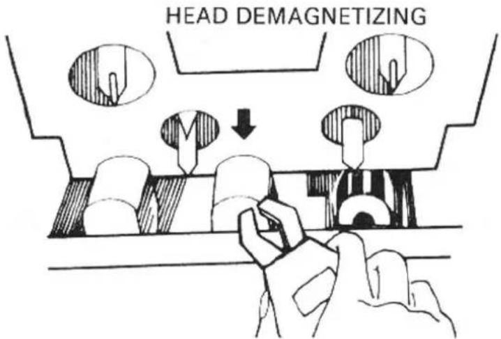
DEMAGNETIZING
The tape heads, capstan and tape guides gradually become magnetized with use, which will eventually affect the sound quality of your tapes. Demagnetizing should follow cleaning, but need not take place as often as cleaning, once after every 20 to 30 hours of use should suffice.
A demagnetizer may be purchased at a moderate cost from any dealer carrying tape recording accessories. Follow the instruction supplied with the demagnetizer.
CAUTION: Push the power switch off before you attempt demagnetizing
LUBRICATION
The RD-1000M has been fully lubricated at the factory. No other lubrication should be necessary for some time. If lubrication should become necessary at some future date, be sure to have this done by a qualified technician only.
HUM
In any high fidelity installation, hum may be caused by interconnecting associated equipment. If the addition of the RD-1000M to your system is accompanied by previously nonexistent hum reverse the AC line plug in its socket. If this does not help, you may have defective interconnecting cables or the cables may be located too near a strong AC field, such as a television, power transformer, AC motor, or power lines. Do not attempt changes to plug connections in the U.K. in any attempt to reduce hum in your system.
SPECIFICATIONS:
| Heads. | SENDUST Core REC/PB Head Dual Gap Ferrite Core Erase Head | ||
| Track. | 4 Track/2 Channel | ||
| Tape Speed | 4.8cm/sec. (1-7/8 ips) | ||
| Motors | FG Servo motor (capstan) DC Servo motor (winding) | ||
| Wow and Flutter | 0.15% (DIN) 0.045% (WRMS) | ||
| Fast Wind Time | Approximately 90 Seconds (C-60) | ||
| Frequency Response | Normal, LH Tape ±3dB | ||
| Chromium Tape | 30 - 15,000Hz ±3dB | ||
| Metal Tape | 30 - 16,000Hz ±3dB | ||
| Signal-to-Noise Ratio (Chromium) | Dolby NR out: Better than 55dB (Weighted) | ||
| Dolby NR in: Better than 64dB (Weighted) | |||
| Input Sensitivity/Impedance. | MIC 0.4mV/2.3 kohms | ||
| LINE 82mV/82 kohms | |||
| DIN 0.3 mV/10 kohms | |||
| Output Level (0 VU, 1kHz=160pwb/mm) | LINE 390mV | ||
| DIN 390mV | |||
| Tape Selectors. | BIAS(%) | EQUALIZER(μS) | |
| Normal,LH Tape | 100 | 120 | |
| Chromium Tape | 150 | 70 | |
| Metal Tape | 200 | 70 | |
| Power Requirements | 120, 220 or 240V 50/60Hz | ||
| Power consumption. | 25 watts (max.) | ||
| Dimensions (overall) | W 430mm (11-15/16") | ||
| H 110mm (4-11/32") | |||
| D 290mm (11-13/32") | |||
| Weight (net) | 7.6kg/16.72 lbs. | ||
Specifications and design subject to possible modification without notice.
Dolby and Dolbyized are trademarks of Dolby Laboratories.
Noise reduction under licence from Dolby Laboratories.


- OWNER'S MANUAL
- RD-1000m
- INTRODUCTION
- POWER SUPPLY CONNECTION
- INSTALLATION
- CONNECTION TO RE- CEIVER OR AMPLIFIER
- EXCLUSIVE NOTE FOR U.K.
- MICROPHONE AND HEADPHONE CONNECTION
- CONTROL FUNCTIONS
- (1)
- EJECT BUTTON
- (2)
- Phones Jack
- (3)
- Power Switch
- (4)
- Cassette Trap Door
- (5)
- Rewind Button (◀◀)
- (6)
- STOP BUTTON (■)
- (7)
- Record Button (●)
- (8)
- Fast Forward Button (▶▶)
- but
- with the RECO
- (10)
- Pause Button (Ⅲ)
- (11)
- AUTO REWIND/REPEAT
- SWITCH
- (12)
- TIMER RECORDING/PLAYING SWITCH
- (13)
- Dolby NR Switch
- (14)
- TAPE SELECTOR SWITCHES
- (15)
- Rec Level Control
- (16)
- Microphone Jacks
- (17)
- Tape Counter
- (18)
- Reset Button
- (19)
- Memory Button
- (20)
- VU Meters
- (21)
- INDICATORS
- AUTOMATIC SHUTOFF SYSTEM
- CASETTE TAPES
- BEFORE RECORDING OR PLAYBACK/CASSETTE INSERTION
- RECORDING
- PLAYBACK
- HOW TO OPERATE THE UNIT WITH TIMER
- Recording with timer
- Playback with timer
- CLEANING
- DEMAGNETIZING
- LUBRICATION
- HUM
Märke : ROTEL
Modell : RD-1000M
Kategori : Kassettspelare