DPRS10 - Enceinte audio Diamond Audio - Notice d'utilisation et mode d'emploi gratuit
Retrouvez gratuitement la notice de l'appareil DPRS10 Diamond Audio au format PDF.

| Type de produit | Caisson de basses amplifié |
| Marque | Diamond Audio |
| Modèle | DPRS10 |
| Dimensions (L x l x H) | 310 x 230 x 78 mm (12.2 x 9 x 3 pouces) |
| Poids | Environ 5,5 kg (estimé) |
| Puissance RMS | 120 W |
| Puissance maximale | 300 W |
| Réponse en fréquence | 20 Hz - 180 Hz |
| Filtre passe-bas | 50 Hz - 180 Hz (réglable) |
| Filtre subsonique | 20 Hz |
| Boost des basses | 0 à +12 dB |
| Impédance du haut-parleur | 4 ohms |
| Haut-parleur | 10 pouces |
| Sensibilité d'entrée haut niveau | 1,0 V |
| Sensibilité d'entrée bas niveau | 300 mV |
| Rapport signal/bruit | > 90 dB |
| Distorsion harmonique totale | < 0,5 % |
| Alimentation | 12 V CC (batterie véhicule) |
| Fusible | 20 A |
| Entrées audio | RCA (bas niveau) et haut niveau (connecteur fourni) |
| Contrôle à distance | Oui (câble de télécommande inclus) |
| Phase | Commutable (0/180°) |
| Mise en veille automatique | Oui (auto power on/off) |
| Installation | Sous siège ou dans le coffre |
| Kit de fixation | Inclus (4 supports et vis) |
| Entretien | Nettoyer avec un chiffon sec et doux |
| Sécurité | Éviter de percer dans le réservoir de carburant |
FOIRE AUX QUESTIONS - DPRS10 Diamond Audio
Questions des utilisateurs sur DPRS10 Diamond Audio
0 question sur cet appareil. Repondez a celles que vous connaissez ou posez la votre.
Poser une nouvelle question sur cet appareil
Téléchargez la notice de votre Enceinte audio au format PDF gratuitement ! Retrouvez votre notice DPRS10 - Diamond Audio et reprennez votre appareil électronique en main. Sur cette page sont publiés tous les documents nécessaires à l'utilisation de votre appareil DPRS10 de la marque Diamond Audio.
MODE D'EMPLOI DPRS10 Diamond Audio
DIAMOND
AUDIO

DIAMOND
DPRS10
10" Low Profile
Amplified Subwoofer
©2021 Diamond Audio. All rights reserved.
(a division of CV & DA Holdings, Inc.)
USER MANUAL
Introduction
Cerwin Vega Mobile Amplifiers
Thank you for purchasing a Cerwin Vega Mobile amplifier for your car audio system. You have chosen Cerwin Vega Mobile because you deserve the best!
Cerwin Vega Mobile amplifiers are designed and engineered to the highest quality standards in the industry to create the ultimate listening experience in your vehicle. For optimal performance of this product, it is highly recommended that you have your new amplifier installed by an authorized Cerwin Vega Mobile dealer. Our authorized dealers have the necessary experience and installation equipment to ensure that your amplifier will deliver maximum performance and explain all the details pertaining to our warranty coverage as well.
If you decide to install the amplifier by yourself, please thoroughly read through this manual before getting started. This manual will help familiarize yourself with this amplifier and guide you through the installation process and procedures.
Please contact your local authorized Cerwin Vega Mobile dealer if you have any questions regarding the instructions in this manual or the amplifier's operation capabilities. If you require additional assistance, please contact the Cerwin Vega Mobile Technical Support Department during business hours at 213-261-4161.
Specifications
| MODEL: | DPRS10 |
| Power | 120 WRMS/300 WMAX |
| THD | <0.5% |
| Signal-to-noise ratio | >90dB |
| Frequency response | 20Hz - 180Hz |
| Input sensitivity, high level | 1.0V |
| Input sensitivity, low level | 300V |
| Low Pass Filter | 50Hz - 180Hz |
| Bass Boost | 0 to + 12dB |
| Subsonic Filter | 20Hz |
| Fuse rating | 20A |
| Subwoofer | 10 inch , 4 ohm |
| Dimensions(L x W x H) inches/mm | 12.2"(310) x 9"(230)x 3"(78) |
All specifications subject to change without notice.
Warranty
Thank you for purchasing a Cerwin Vega Mobile product and we hope to provide you with countless hours of listening enjoyment.
Please take a brief moment to register your new product. By registering your new product, you will receive benefits such as:
- Important product notifications that may pertain to your purchase.
- Confirmation and record of ownership in case of loss or theft.
- Knowledgeable customer service and technical assistance pertaining to your product.
Register your new product by completely filling out this Product and Warranty Registration card or register online at www.cerwinvegamobile.com.
Registration is voluntary and failure to register will not diminish your limited warranty rights.
Limited Warranty (U.S.A.)
Cerwin Vega Mobile warrants all of our amplifiers and speakers to be free of defects in materials and workmanship for a period of one (1) year.
This warranty is non-transferable and applies only to the original purchaser from an authorized Cerwin Vega Mobile dealer. If service is required and necessary under this warranty due to manufacturing defect or malfunction, then Cerwin Vega Mobile will repair and/or replace defective product with either new or remanufactured like product at no charge at our discretion.
Damage to product caused by the following will not be covered under this warranty: abuse, accident, misuse, neglect, modifications, repairing attempts, seller/installer misrepresentation.
This warranty does not cover any incidental, consequential, or cosmetic damage due to accidents or normal wear and tear, nor does it cover the cost of removing or reinstallation of the product.
Warranty is void if the product's serial number has been removed, defaced, and/or tampered with.
Warranty Procedure:
We recommend that you contact your Cerwin Vega Mobile authorized dealer where your original purchase was made to initiate all warranty claims. Our authorized dealers can guide you through the warranty procedure to ensure that your claim will be processed in a timely manner. All warranty returns must be accompanied with a proof of purchase (a copy of the original sales receipt) and be shipped freight prepaid to our facility with an RA (Return Authorization) number clearly marked on the outside of the package. Direct returns from consumers or non-authorized dealers will be refused if shipped without a valid RA number authorized by Cerwin Vega Mobile beforehand.
INTERNATIONAL
Products purchased outside of the U.S.A. are covered only by that country's distributor and not by Cerwin Vega Mobile U.S.A.
Please Ship All Warranty Claims With Pre-Authorized RA Number To:
CV&DA Holdings, Inc.
ATTN: Customer Service Department
3761 St. Hill Street
Los Angeles, CA 90007 USA
Please Contact Customer Service for Further Warranty Information:
U.S.A.
Tel: 213-261-4161 / Fax: 213-947-4767
Troubleshooting
Features/Functions
Troubleshooting
If you experience operation or performance problems with this product, compare your installation with the electrical wiring diagram on the previous pages. If problems persist, read the following troubleshooting tips which may help eliminate the problems.
SYMPTOM
POSSIBLE REMEDY
| Amplifier will not power up. | Check to make sure you have a good ground connection.Check that the Remote Input (Turn-On) has at least 5VDC.Check that there is battery power on the (+) terminal.Check that there is at least 12v.Check all fuse, replace if necessary.Make sure that the Protection LED is not illuminated. If it is lit, shut off the amplifier briefly, and then repower it. |
| Protection LED comes on when amplifier is powered up | Check for short circuits on speaker leads.Turn down the volume control on the head unit to prevent overdriving.Remote speaker leads, and reset the amplifier. If the Protection LED still comes on, then the amplifier is faulty and needs servicing. |
| No output. | Check that all fuses are OK.Check that unit is properly grounded.Check that the Remote Input (Turn-On) has at least 5VDC.Check that the RCA audio cables are plugged into the proper inputs.Check all speaker wiring. |
| Low output. | Reset the Level Control.Check the Crossover Control settings. |
| High hiss in the sound. | Disconnect all RCA inputs to the power sub's control panel. If the hiss disappears, then plug in the component driving the amplifier and unplug its inputs. If the hiss disappears at this point, go on until the faulty/noisy component is found.It is best to set the amplifier's input level control as low as possible. The best subjective signal-to-noise ratio is achieved in this manner. Try to set the head unit as high as possible (without distortion) and the amp input level as low as possible. |
| Squealing noise is present. | Check for improperly grounded RCA interconnects. |
| Distorted sound. | Check that the Input Level Control is set to match the signal level of the head unit. Always try to set the Input Level as low possible.Check that all crossover frequencies are properly set.Check for short circuits on the speaker leads. |
| Amplifier gets very hot. | Check that the minimum speaker impedance for the amp model is correct.Check that there is good air circulation around the amp. In some applications, it may be necessary to add and external cooling fan. |
| Engine noise (static type) | This is usually caused by poor quality RCA cables, which can pick up radiated noise. Use only the best quality cables, and route them away from power cables. |
| Engine noise (alternator whine) | Check that the RCA grounds are not shorted to the vehicle chassisCheck that the head unit is properly grounded. |
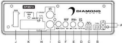
Panel controls and features
text_image
DPRS10 DIAMOND J K H I G F E D C B AA. POWER STATUS LED
This bi-color LED glows green when power is on and no problems are present. If one of the protection circuits comes on, it will change to red.
B.PHASE SHIFT
Use this switch to help compensate for time alignment problems in the system. Such problems usually result from having the subwoofer at a different distance from the listener than the other speakers in the system.
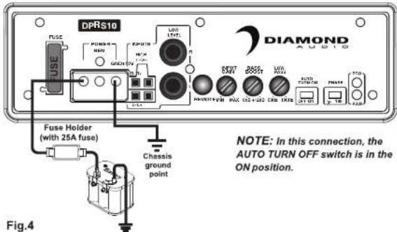
C. AUTO POWER ON
The AUTO POWER ON(ON/OFF) is for high level (speaker-level) connections. When the switch is in the "ON" position, the subwoofer AUTO POWER ON when there is signal input. If the amplifier detected no signal input, the amplifier will auto turn off. If you prefer to use the remote turn on/off connection, the switch is in the OFF position.
| Note: Please connect the remote terminal to the remote output of head unit as Fig.4. When you hear the unit turn ON/OFF POP noise from the subwoofer. |
D.LOW PASS FILTER
This control permits you define the frequency range you want the subwoofer amplifier to receive. The subwoofer will reproduce all sound BELOW the frequency you set.
| Note: The low pass filter frequency can be higher or lower than the standard.There have +/-20% tolerance. |
E.BASS BOOST
The BASS BOOST feature will increase the sound level in the bass frequencies.
F. INPUT GAIN CONTROL
After you have installed your system, turn this control to minimum.
Turn the head unit on (and the subwoofer will turn on via the remote connection). Turn the head unit volume to about 2/3 full level.
Slowly turn up the subwoofer input gain control until you hear a small amount of distortion. Then reduce the level until the distortion is completely gone. Level the control at this setting.
G.REMOTE LEVEL CONTROL PORT
Attach the included remote level control to control the volume level of the subwooer independently.
H.HIGH LEVEL (speaker level) INPUTS
If your head unit does not have RCA outputs you can use the speaker outputs for the audio source for the subwoofer. Use the supplied cable and wire harness and connect the outputs properly as shown in the connection diagram in this manual.
I. LOW LEVEL RCA INPUTS
Low level inputs are the recommended way to introduce the audio signal to the subwoofer if RCA outputs are present on your head unit or other signal source (such as a sound processor).
J.FUSE
Do not use a fuse with a different value and NEVER replace the fuse with a wire or coin.
K.POWER INPUT TERMINAL
Features/Functions
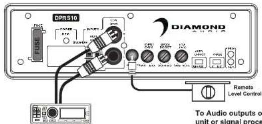
Low Level Input Wiring
Low-level (RCA) input wiring is preferred for best audio performance. Most trunk or hatchback installations will require a 15-20 feet RCA cable, while pickup trucks and under-seat installations will require a 6-12 feet RCA cable. Always use a high quality cable.
NOTE: Do not connect BOTH the high level and low level inputs from your receiver to your amplifier at the same time!
Fig.1
text_image
DPRS10 FUSE PWM RXR USB LCA I2A PWM PWM PWM PWM PWM PWM PWM PWM PWM PWM PWM PWM PWM PWM PWM PWM PWM PWM PWM PWM PWM PWM PWM PWM PWM PWM PWM PWM PWM PWM PWM PWM PWM PWM PWM PWM PWM PWM PWM PWM PWM PWM PWM PWM PWM PWM PWM PWM PWM PWM Remote Level Control To Audio outputs of unit or signal processHigh Level Input Wiring
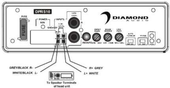
The high level input(s) should only be used when your receiver lacks RCA outputs. If the RCA outputs are not present, connect the speaker outputs from the receiver to the high level input connector of the amplifier. Be sure to observe polarity to avoid audio phase problems.
NOTE: Do not connect BOTH the high level and low level inputs from your receiver to your amplifier at the same time!
Fig.2
text_image
DPRS10 FUSE POWER REN QND+2V INPUTS LED LED+ R R R R R R R R R R R R R R R R R R R R R R R R R R R R R R R R R R R R R R R R R R R R R R R R R R R + GREY L+ WHITE To Speaker Terminals of head unitInstallation
text_image
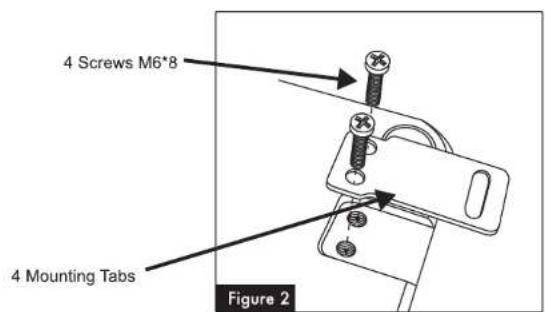
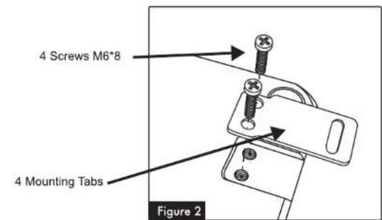
4 Screws M6*8 4 Mounting Tabs Figure 2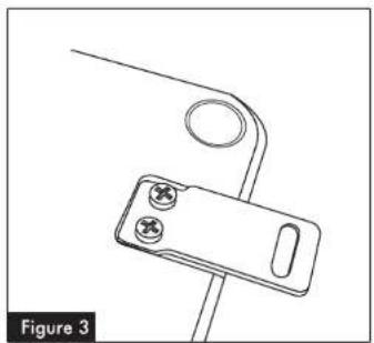
natural_image
Technical line drawing of a mechanical clamp or bracket component (no text or symbols)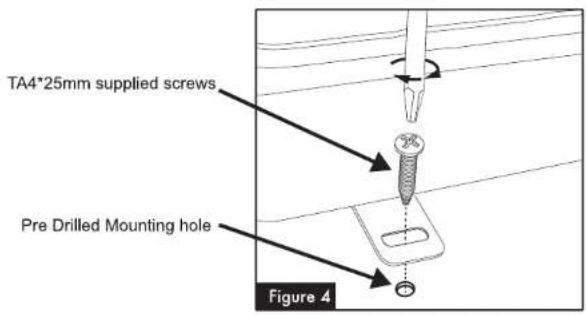
text_image
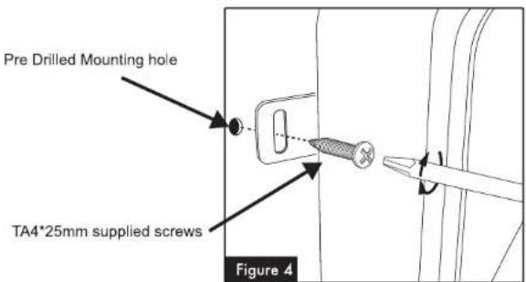
TA4*25mm supplied screws Pre Drilled Mounting hole Figure 4Installation
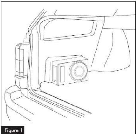
Under a seat
1 - The seat must be positioned in its normal fixed position.
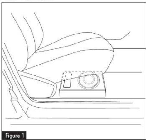
2 - Decide the best location possible that suits your automobile and space available, checking that the enclosure doesn't hamper the seat mobility (See Figure 1)
3 - Ensure the area for subwoofer location is clean and tidy. Any loose objects must be removed.
4 - Once the location has been decided, mark the screw hole positions for the fixing brackets.
5 - Drill holes of 2 mm for the 4 fixing brackets, at your defined locations
6 - Fix the clamps to the subwoofer basket with the four screws M6*8 (the fixing clamps have a mounting direction system) (Figure 2 & 3)
7 - Position the subwoofer so that the holes correspond to the M4*20 supplied screws and fix it. (Figure 4)
8 - Please make sure the subwoofer enclosure is tightly fixed

CAUTION!! Make sure to not drill or screw into the vehicles gas tank!!!

Under a seat
natural_image
Line drawing of a car's seat and dashboard with a small inset component (no text or symbols)Installation
Power Connections
Connect the ground terminal to the closest point on the chassis of the vehicle. Keep this ground wire to less than 39" (100 cm) in length. Use 8 gauge (or heavier) wire.
Connect the remote terminal to the remote output of head unit using 16 gauge (or heavier) wire.
Connect a fuse holder (with a 25A fuse) within 18" (45 cm) of the car battery, and run 8 gauge (or heavier) cable from this fuse to the amplifier location. Then connect the fuse holder to the "BATT+" (+12V) connection on the subwoofer rear panel.
Fig.3
text_image
DPRS10 FUSE POWER MAX GND L2A PSPUTR L2A LOW L2A S EOUT MAX GND L2A PSPUTR L2A MAX GND L2A PSPUTR L2A MAX GND L2A PSPUTR L2A MAX GND L2A PSPUTR L2A MAX GND L2A PSPUTR L2A MAX GND L2A PSPUTR L2A MAX GND L2A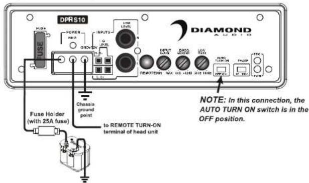
text_image
DPRS10 POWER HI-0 ON/OV INPUTS LOW LEVEL R REMOTE INPUT DOWN BACK RIGHT LOW DOWN AUTO TURN ON PAUM TOO OFF FUSE Holder (with 25A fuse) Chassis ground point to REMOTE TURN-ON terminal of head unit NOTE: In this connection, the AUTO TURN ON switch is in the OFF position. DIAMONDInstallation
We included a fixing kit to ensure the subwoofer remains securely mounted.
Two types of installation are possible
In the trunk
natural_image
Line drawing of a vehicle's front and side view showing a camera mounted on the dashboard (no text or symbols)1 - Rear seats must be positioned in their normal fixed position.
2 - Decide the best location possible that suits your automobile and space available. The best and most secure location for optimum sound quality is behind the rear seats, in the trunk floor (see Figure 1).
3 - Ensure the area for subwoofer location is clean and tidy. Any loose objects must be removed, as they could knock and damage the subwoofer.
4 - Once the location has been decided, mark the screw hole positions for the fixing brackets.
5 - Drill holes of 2 mm for the 4 fixing brackets, at your defined locations.
6 - Fix the clamps to the subwoofer basket with the four screws M6*8 (the fixing clamps have a mounting direction system). (Figure 2 & 3)
7 - Position the subwoofer so that the holes correspond to the TA4*25 supplied screws and fix it. (Figure 4)
8 - Please make sure the subwoofer enclosure is tightly fixed

CAUTION!! Make sure to not drill or screw into the vehicles gas tank!!!

Installation
text_image
4 Screws M6*8 4 Mounting Tabs Figure 2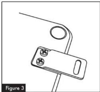
natural_image
Technical line drawing of a mechanical clamp or bracket component (no text or symbols)