
3008WFP - Téléviseur DELL - Notice d'utilisation et mode d'emploi gratuit
Retrouvez gratuitement la notice de l'appareil 3008WFP DELL au format PDF.

| Type de produit | Moniteur LCD 30 pouces |
| Marque | Dell |
| Modèle | 3008WFP |
| Taille d'écran | 30 pouces (756,228 mm de diagonale) |
| Résolution native | 2560 x 1600 pixels |
| Type de dalle | Active matrix TFT LCD |
| Luminosité | 370 cd/m² (typique) |
| Contraste | 1000:1 (typique), 3000:1 (dynamique) |
| Temps de réponse | 8 ms (gris à gris typique), 12 ms (noir à blanc max) |
| Angle de vision | 178° horizontal et vertical (typique) |
| Connecteurs vidéo | VGA, DVI-D (x2), DisplayPort, HDMI, Composante, S-Vidéo, Composite |
| Hub USB | 1 amont (USB 2.0), 4 aval |
| Lecteur de cartes | 9-en-1 (CF, xD, SD, MS, MMC, etc.) |
| Fonctions | Picture by Picture (PBP), OSD multilingue |
| Alimentation | 100-240 VAC, 50/60 Hz |
| Consommation | 250 W max, 163 W typique, <2 W veille |
| Fixation | VESA 100 mm, pied amovible |
| Inclinaison | -3° à 19° (avant/arrière) |
| Pivot | ±30° |
| Extension verticale | 90 mm |
| Dimensions (affichage) | 641,28 mm x 400,80 mm |
| Poids | Non spécifié dans la notice |
| Sécurité | Emplacement pour cadenas de sécurité Kensington |
| Entretien | Chiffon doux et propre, éviter les nettoyants abrasifs |
| Accessoires inclus | Câbles VGA, DVI, USB, CD avec pilotes et manuel |
FOIRE AUX QUESTIONS - 3008WFP DELL
Questions des utilisateurs sur 3008WFP DELL
0 question sur cet appareil. Repondez a celles que vous connaissez ou posez la votre.
Poser une nouvelle question sur cet appareil
Téléchargez la notice de votre Téléviseur au format PDF gratuitement ! Retrouvez votre notice 3008WFP - DELL et reprennez votre appareil électronique en main. Sur cette page sont publiés tous les documents nécessaires à l'utilisation de votre appareil 3008WFP de la marque DELL.
MODE D'EMPLOI 3008WFP DELL
Dell™ 3008WFP Flat Panel Monitor User's Guide
About Your Monitor
Product Features
Identifying Parts and Controls
Monitor Specifications
Universal Serial Bus (USB) Interface
Plug and Play Capability
Card Reader Specifications
Maintenance Guidelines
Setting Up the Monitor
Connecting the Monitor
Organizing the Cables
Attaching the Soundbar (Optional)
Removing the Stand
Attaching the Stand
Operating the Monitor
Using the Front Panel Controls
Using the On-Screen Display (OSD)
Setting the Optimal Resolution
Using the Dell Soundbar (Optional)
Using the Tilt, Swivel, and Vertical Extension
Solving Problems
Monitor Specific Troubleshooting
Common Problems
Video Problems
Product Specific Problems
Universal Serial Bus (USB) Specific Problems
Troubleshooting the Dell™ Soundbar
Troubleshooting the Card Reader
Appendix
Safety Instructions
FCC Notice (U.S. Only) and Other Regulatory Information
Contacting Dell
Notes, Notices, and Cautions

NOTE: A NOTE indicates important information that helps you make better use of your computer.

NOTICE: A NOTICE indicates either potential damage to hardware or loss of data and tells you how to avoid the problem.

CAUTION: A CAUTION indicates a potential for property damage, personal injury, or death.
Information in this document is subject to change without notice. © 2007-2009 Dell Inc. All rights reserved.
Reproduction in any manner whatsoever without the written permission of Dell Inc. is strictly forbidden.
Trademarks used in this text: Dell and the Dell logo are trademarks of Dell Inc; Microsoft, Windows, and Windows NT are registered trademarks of Microsoft Corporation;
Adobe is a trademark of Adobe Systems Incorporated, which may be registered in certain jurisdictions.
Other trademarks and trade names may be used in this document to refer to either the entities claiming the marks and names or their products. Dell Inc. disclaims any proprietary interest in trademarks and trade names other than its own.
Model 3008WFPt
December 2009 Rev. A05
Back to Contents Page
About Your Monitor
Dell™ 3008WFP Flat Panel Monitor User's Guide
Product Features
Identifying Parts and Controls
Monitor Specifications
Universal Serial Bus (USB) Interface
Plug and Play Capability
Card Reader Specifications
Maintenance Guidelines
Product Features
The 3008WFP flat panel display has an active matrix, thin-film transistor (TFT), liquid crystal display (LCD). The monitor features include:
■ 30-inch (756.228 mm) viewable area display.
■ 2560 x 1600 resolution, plus full-screen support for lower resolutions.
■ Wide viewing angle to allow viewing from a sitting or standing position, or moving side-to-side.
■ Tilt, swivel and vertical extension capabilities.
■ Removable pedestal and VESA 100 mm mounting holes for flexible mounting solutions.
■ Plug and play capability if supported by your system.
■ On-Screen Display (OSD) adjustments for ease of set-up and screen optimization.
■ Software and documentation CD includes an information file (INF), Image color Matching File (ICM), and product documentation.
■ Security lock slot.
■ 9-in-2 USB 2.0 Card Reader (CF I/II, xD, SD/Mini SD, MS/HSMD/MSPRO, MMC).
■ Support VGA, DVI-D, DisplayPort, HDMI, Component, S-Video and Composite video signals.
■ Support Picture by Picture (PBP) Select mode.
Identifying Parts and Features
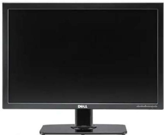
Front View
natural_image
Front view of a black Dell computer monitor with a stand (no visible text or symbols on the screen)Front View
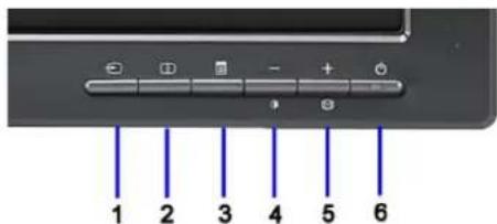
Front panel controls
Label Description
1 Video input select
2 Picture by Picture (PBP) Select
3 OSD Menu/Select
4 Brightness & Contrast/Down (-)
5 Auto-adjust/Up (+)
6 Power button (with power light indicator)
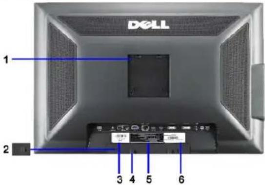
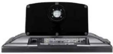
Back View
natural_image
Front view of a Dell computer monitor with a blue indicator line and labeled port (no text or symbols on the device itself)Back view
Back View with monitor stand
| Label | Description | Use |
| 1 | VESA mounting holes (100mm) (Behind attached base plate) | To mount the monitor. |
| 2 | Security lock slot | To help secure your monitor. |
| 3 | Barcode serial number label | To contact Dell for technical support. |
| 4 | Dell Soundbar mounting brackets (2) | To attach the optional Dell Soundbar. |
| 5 | Regulatory rating label | Lists the regulatory approvals. |
| 6 | Service tag label | Refer to this label if you need to contact Dell for technical support. |
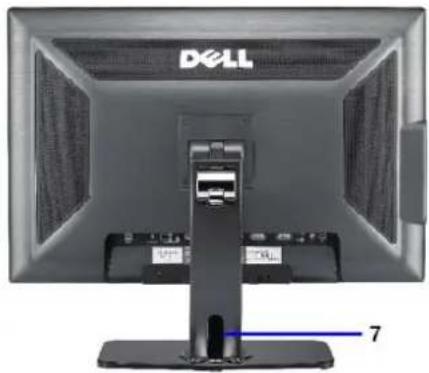
| 7 | Cable holder | Help organize cables by placing them in the holder. |
Side View
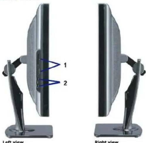
Label Description
| 1 | Card reader: for details, see Card Reader Specifications. |
| 2 | USB downstream ports. |

NOTE: To use the USB connectors on your monitor, connect the USB cable to your computer and the USB upstream connector to your monitor.
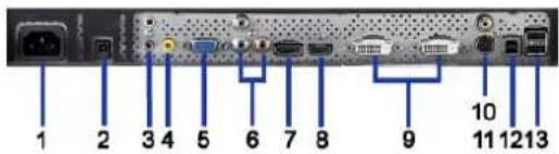
Bottom View
natural_image
Black laptop with a circular headlight and visible internal components (no text or symbols)Bottom view
Bottom view with monitor stand
| Label | Description | Use |
| 1 | AC power cord connector | Connect the power cord to wall outlet. |
| 2 | DC power connector for Dell Soundbar | Connect the power cord for the Soundbar (optional). |
| 3 | Audio connectors | Connect the HDMI 2.0 channel or 5.1 channel audio output devices. Connect the front left/right channel output to the green connector. Use this connector for 2.0/2.1 channel audio connection. Connect the rear left/right channel output to the black connector. Use this connector for 5.1 channel audio connection. |
| 4 | Audio connector | Connect the center/subwoofer channel output to the yellow connector. Use this connector for 5.1 channel audio connection. |
| 5 | VGA connector | Connect the VGA cable from your computer to the monitor. |
| 6 | Component video connectors | Connect devices such as a DVD player, set-top box, or cable TV box. |
| 7 | DisplayPort connector | Connect the DisplayPort cable from your computer to the monitor. |
| 8 | HDMI connector | Connect devices such as a DVD player or set-top box. |
| 9 | DVI connectors | Connect the DVI cable from your computer to the monitor. |
| 10 | Composite video connector | Use this to connect devices such as VCR or DVD player. |
| 11 | S-Video connector | Use this to connect devices such as a video game system, a digital camera, or a DVD player. |
| 12 | USB upstream port | Connect the USB cable that came with your monitor to the monitor and the computer. Once this cable is connected you can use the USB connectors on the side and bottom of the monitor. |
| 13 | USB downstream ports | Connect your USB devices. |
Monitor Specifications
The following sections give you information about the various power management modes and pin assignments for various connectors for your monitor.
Power Management Modes
If you have VESA's DPM™ compliance display card or software installed in your PC, the monitor can automatically reduce its power consumption when not in use. Mode*. If the computer detects input from keyboard, mouse, or other input devices, the monitor automatically resumes functioning. The following table shows that of this automatic power saving feature:
| VESA Modes | Horizontal Sync | Vertical Sync | Video | Power Indicator | Power Consumption |
| Normal operation (with Dell Soundbar and USB active) | Active | Active | Active | Blue | 250 W (maximum) |
| Normal operation | Active | Active | Active | Blue | 163 W (typical) |
| Active-off mode | Inactive | Inactive | Blanked | Amber | Less than 2 W |
| Switch off | - | - | - | Off | Less than 1 W |
The OSD will only function in the normal operation mode. When the menu or plus buttons are pressed in Active-off mode, one of the following messages will be d Analog Input In Power Save Mode. Press Computer Power Button or Any Key on Keyboard or Move Mouse
OR Digital Input In Power Save Mode. Press Computer Power Button or Any Key on Keyboard or Move Mouse Activate the computer and the monitor to gain access to the OSD.
NOTE: While using the DisplayPort connector at 230v/50Hz, the DisplayPort consumes approximately 0.25W more than the VGA or DVI-D while in sleep n * Zero power consumption in OFF mode can only be achieved by disconnecting the main cable from the monitor.
Pin Assignments
VGA Connector

| Pin Number | 15-pin Side of the Connected Signal Cable |
| 1 | Video-Red |
| 2 | Video-Green |
| 3 | Video-Blue |
| 4 | GND |
| 5 | Self-test |
| 6 | GND-R |
| 7 | GND-G |
| 8 | GND-B |
| 9 | +5V |
| 10 | DDC-GND |
| 11 | GND |
| 12 | DDC-SDA |
| 13 | H-sync |
| 14 | V-sync |
| 15 | DDC-SCL |
DVI Connector
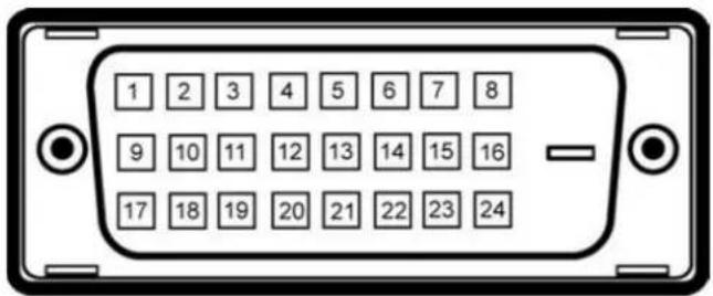

NOTE: Pin 1 is at the top left.
| Pin Number | 24-pin Side of the Connected Signal Cable |
| 1 | T.M.D.S. Data 2- |
| 2 | T.M.D.S. Data 2+ |
| 3 | T.M.D.S. Data 2/4 Shield |
| 4 | T.M.D.S. Data 4- |
| 5 | NT.M.D.S. Data 4+ |
| 6 | DDC Clock |
| 7 | DDC Data |
| 8 | No Connect |
| 9 | T.M.D.S. Data 1- |
| 10 | T.M.D.S. Data 1+ |
| 11 | T.M.D.S. Data 1/3 Shield |
| 12 | T.M.D.S. Data 3- |
| 13 | T.M.D.S. Data 3+ |
| 14 | +5V Power |
| 15 | Self Test |
| 16 | Hot Plug Detect |
| 17 | T.M.D.S. Data 0- |
| 18 | T.M.D.S. Data 0+ |
| 19 | T.M.D.S. Data 0/5 Shield |
| 20 | T.M.D.S. Data 5- |
| 21 | T.M.D.S. Data 5+ |
| 22 | T.M.D.S. Clock Shield |
| 23 | T.M.D.S. Clock + |
| 24 | T.M.D.S. Clock - |
20-pin DisplayPort Connector
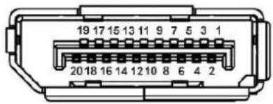
| Pin Number | 20-pin Side of the Connected Signal Cable |
| 1 | ML Lane 3(n) |
| 2 | GND |
| 3 | ML Lane 3(p) |
| 4 | ML Lane 2(n) |
| 5 | GND |
| 6 | ML Lane 2(p) |
| 7 | ML Lane 1(n) |
| 8 | GND |
| 9 | ML Lane 1(p) |
| 10 | ML Lane 0(n) |
| 11 | GND |
| 12 | ML Lane 0(p) |
| 13 | GND |
| 14 | GND |
| 15 | AUX CH (p) |
| 16 | GND |
| 17 | AUX CH (n) |
| 18 | Hot Plug Detect |
| 19 | Return |
| 20 | DP PWR |
19-pin HDMI Connector
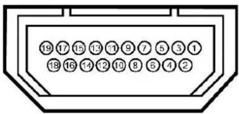
Pin Number 19-pin Side of the Connected Signal Cable
1 T.M.D.S. Data 2-
2 T.M.D.S. Data 2 Shield
3 T.M.D.S. Data 2+
4 T.M.D.S. Data 1+
5 T.M.D.S. Data 1 Shield
6 T.M.D.S. Data 1-
7 T.M.D.S. Data 0+
8 T.M.D.S. Data 0 Shield
9 T.M.D.S. Data 0-
10 T.M.D.S. Clock +
11 T.M.D.S. Clock Shield
12 T.M.D.S. Clock -
13 CEC
14 Reserved(N.C. on device)
15 SCL
16 SDA
17 DDC/CEC Ground
18 +5V Power
19 Hot Plug Detect
S-video Connector
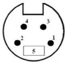
Pin 5-pin Side of the Connected Signal Cable Number (Cable not included)
| 1 | GND |
| 2 | GND |
| 3 | LUMA |
| 4 | CHROMA |
| 5 | GND |
Composite Video Connector

Luma Composite Chroma
Component Video Connector

Pin Number 3-pin Side of the Connected Signal Cable (Cable not included)
| 1 | Y (Luminance signal) |
| 2 | Pb (Color differential signal) |
| 3 | Pr (Color differential signal) |
Universal Serial Bus (USB) Interface
This section gives you information about the USB ports that are available on the left side of your monitor.
NOTE: This monitor supports High-Speed Certified USB 2.0 interface.
| Transfer speed | Data Rate | Power Consumption |
| High speed | 480 Mbps | 2.5W (Max., each port) |
| Full speed | 12 Mbps | 2.5W (Max., each port) |
| Low speed | 1.5 Mbps | 2.5W (Max., each port) |
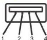
USB Upstream Connector
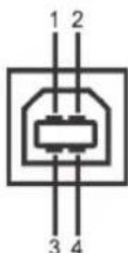
| Pin Number | 4-pin Side of the connector |
| 1 | DMU |
| 2 | VCC |
| 3 | DPU |
| 4 | GND |
USB Downstream Connector
| Pin Number | 4-Pin Side of the Signal Cable |
| 1 | VCC |
| 2 | DMD |
| 3 | DPD |
| 4 | GND |
USB Ports
• 1 upstream - rear
• 4 downstream - 2 on rear; 2 on left side
NOTE: USB 2.0 functionality requires a USB 2.0-capable computer.
NOTE: The monitor's USB interface works only when the monitor is on or in power save mode. If you turn off the monitor and then turn it on, the attached p to resume normal functionality.
Plug and Play Capability
You can install the monitor in any Plug and Play-compatible system. The monitor automatically provides the computer system with its Extended Display Identificat Channel (DDC) protocols so the system can configure itself and optimize the monitor settings. Most monitor installations are automatic; you can select different information about changing the monitor settings, see Operating the Monitor.
Card Reader Specifications
Overview
- The Flash Memory Card Reader is a USB storage device that allows users to read and write information from and into the memory card.
- The Flash Memory Card Reader is automatically recognized by Windows® 2000, XP, Vista & Windows® 7.
- Once installed and recognized, each separate memory card (slot) appears as a separate drive/drive letter.
- All standard file operations (copy, delete, drag-and-drop, etc.) can be performed with this drive.
Features
The Flash Memory Card Reader has the following features:
• Supports Windows 2000, XP and Vista operating systems.
• No Windows 9X support from Dell.
- Mass Storage Class device (No drivers are required under Windows 2000, XP, Vista & Windows 7).
- USB-IF certification.
• Supports various memory card media.
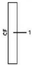
The following table lists the slot to support what kind of memory card:
| Slot Number | Flash memory cards type |
| 1 | Compact Flash type I/II Card (CF I/II)/CF form factor ATA hard drives to USB 2.0 bus |
| 2 | xD memory cardMemory Stick Card (MS)/High Speed Memory Stick (HSMS)/Memory Stick Pro Card (MS PRO)/Memory Stick Duo (with Adapter)Secure Digital Card (SD)/Mini Secure Digital (with Adapter)/ TransFlash Card (with Adapter)MultiMedia Card (MMC)/Reduced Size MultiMedia Card (with Adapter) |
| Cards Type | Support Specification | Memory Card Spec Version | Max. capacity |
| CF | CompactFlash Specification | 2.0 | 128 GB |
| xD | xD Picture Card Specification | 1.2 | 2 GB |
| MS | Memory Stick Standard Format Specification | 1.40-00 | 128 MB |
| MS PRO | Memory Stick Pro Standard Format Specifications | 1.01-01 | 32 GB |
| MD Duo | Memory Stick Duo Standard Format Specifications | 1.10-00 | 128 MB/32 GB |
| SD | SD Memory Card Specifications | 2.0 | 32 GB |
| MMC | MultiMediaCard System Specification | 4.2 | 32 GB |

NOTE: MSPRO : MSPRO includes MSPRO Duo and MS Micro.

NOTE: SD : SD includes MiniSD.

NOTE: MMC : MMC includes RS-MMC.
Flat Panel Specifications
| Screen type | Active matrix - TFT LCD |
| Screen dimensions | 30 inches (30-inch viewable image size) |
| Preset display area: | |
| Horizontal | 641.28 mm (25.25 inches) |
| Vertical | 400.80 mm (15.78 inches) |
| Pixel pitch | 0.2505 mm |
| Viewing angle | 178^ (vertical) typ, 178^ (horizontal) typ |
| Luminance output | 370 cd/m ^2 (typ) |
| Contrast ratio | 1000 to 1 (typ) |
| Dynamic contrast ratio | 3000 to 1 (typ) |
| Faceplate coating | Antiglare with hard-coating 3H |
| Backlight | Wide CCFL (9) backlight system |
| Color Gamut (Typical) | 117%* |
| Response Time | 8ms typical (Grey to Grey) and 12ms maximum (Black to White) |
* 3008WFP color gamut (typical) is based on CIE1976 (117%) and CIE1931 (100.6%) test standards.
Back to Contents Page
Appendix
Dell™ 3008WFP Flat Panel Monitor User's Guide
Safety Instructions
FCC Notice (U.S. Only) and Other Regulatory Information
Contacting Dell

CAUTION: Safety Instructions

CAUTION: Use of controls, adjustments, or procedures other than those specified in this documentation may result in exposure to shock, electrical hazards, and/or mechanical hazards.
For information on safety instructions, see the Product Information Guide.
FCC Notices (U.S. Only) and Other Regulatory Information
For FCC notices and other regulatory information, see the regulatory compliance website located at www.dell.com\regulatory_compliance.
Contacting Dell
For customers in the United States, call 800-WWW-DELL (800-999-3355).

NOTE: If you do not have an active Internet connection, you can find contact information on your purchase invoice, packing slip, bill, or Dell product catalog.
Dell provides several online and telephone-based support and service options. Availability varies by country and product, and some services may not be available in your area. To contact Dell for sales, technical support, or customer service issues:
- Visit support.dell.com.
- Verify your country or region in the Choose A Country/Region drop-down menu at the bottom of the page.
- Click Contact Us on the left side of the page.
- Select the appropriate service or support link based on your need.
- Choose the method of contacting Dell that is convenient for you.
Back to Contents Page
Back to Contents Page
Setting Up Your Monitor
Dell™ 3008WFP Flat Panel Monitor User's Guide
If you have a Dell™ desktop or a Dell™ portable computer with internet access
-
Download and install the latest driver for your graphics card from the Dell Support site at: support.dell.com.
-
Set the resolution to 1920 x 1200/2560 x 1600
NOTE: If you are unable to set the resolution to 1920 x 1200/2560 x 1600, please contact Dell™ to inquire about a graphics adapter that supports these resolutions.
Back to Contents Page
Setting Up Your Monitor
Dell™ 3008WFP Flat Panel Monitor User's Guide
If you have non Dell™ desktop, portable computer, or graphic card
In Windows XP:
- Right-click on the desktop and click Display Properties.
- Select the Settings tab.
- Select Advanced
- Select the Adapter tab. The Adapter Type lists the graphics adapter on your system.
- Download and install the latest drivers from the graphics card manufacturers web site. (You can download drivers for your ATI/NVIDIA graphics card from: www. ATI.com/www.NVIDIA.com.)
- Set the resolution to 1920x1200 for Analog input or 2560x1600 for Digital/Displayport input.
In Windows Vista ^® or Windows 7:
- Right-click on the desktop and click Personalization.
- Click Change Display Settings.
- Click Advanced Settings.
- Identify your graphics controller supplier from the description at the top of the window (e.g. NVIDIA, ATI, Intel etc.).
- Refer to the graphic card provider website for updated driver (for example, http://www. ATI.com OR http://www.NVIDIA.com).
- After installing the drivers for your Graphics Adapter, attempt to set the resolution to 1920 x 1200/2560 x 1600 again.
NOTE: If you are unable to set the resolution to 1920 x 1200/2560 x 1600, contact the computer manufacturer or consider purchasing a graphics adapter that will support the video resolution of 1920 x 1200/2560 x 1600.
Operating the Monitor
Dell™ 3008WFP Flat Panel Monitor User's Guide
Using the Front Panel Controls
Using the On-Screen Display (OSD) Menu
Setting the Optimal Resolution
Using the Dell Soundbar (Optional)
Using the Tilt, Swivel, and Vertical Extension
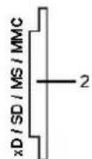
Using the Front Panel
Use the control buttons on the front of the monitor to adjust the characteristics of the image being displayed. As you use these buttons to adjust the controls, an OSD shows the numeric values of the characteristics as they change.
Front panel Button
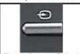
Input Source Select
Description
Use Input Source Select button to select between eight different video signals that may be connected to your monitor.
- VGA input
• DVI-D 1 input
• DVI-D 2 input - DisplayPort input
• HDMI input - Component video input
- S- Video input
• Composite video input
As you cycle through the inputs you will see the following messages to indicate currently selected input source. It may take 1 or 2 seconds for the image to appear.

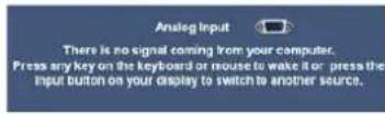
If either VGA or DVI-D input is selected and both VGA and DVI-D cables are not connected, a floating dialog box as shown below appears.

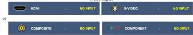
If either S-Video or Composite input is selected and both cables are not connected or the video source is turned off, the screen does no display an image. If any button is pressed (except power button), the monitor displays the following message:
| HDMI: NO INPUT or S-VIDEO: NO INPUT COMPOSITE: NO INPUT or COMPONENT: NO INPUT | ||
| B | Picture by Picture (PBP) Select | Use this button to activate Picture by Picture (PBP) mode adjustment. |
| C | OSD Menu/Select | Use the MENU button to launch the on-screen display (OSD) and select the OSD Menu. See Accessing the Menu System. |
| D | Brightness/Contrast Hot Key | Use this button for direct access to the "Brightness" and "Contrast" control menu. |
| E | Down (-) and Up (+) | Use these buttons to navigate and adjust the slider-bar (decrease/increase ranges) controls in the OSD. |
| F | Auto Adjust | Use this button to activate automatic setup and adjust menu. The following dialog appears on a black screen as the monitor self-adjust to the current input: AUTO ADJUSTMENT IN PROGRESS.... Auto Adjustment allows the monitor to self-adjust to the incoming video signal. After using Auto Adjustment, you can further tune your monitor by using the Pixel Clock (Coarse) and Phase (Fine) controls under DISPLAY SETTINGS. NOTE: Auto Adjust does not occur if you press the button while there are no active video input signals or attached cables. |
| G | Power button (with power light indicator) | Use the Power button to turn the monitor on and off. The blue LED indicates the monitor is on and fully functional. An amber LED indicates DPMS power save mode. |
Using the On-Screen Display (OSD) Menu
Accessing the Menu System
NOTE: If you change the settings and then either proceed to another menu or exit the OSD menu, the monitor automatically saves those changes. The changes are also saved if you change the settings and then wait for the OSD menu to disappear.
1. Push the MENU button to launch the OSD menu and display the main menu.
Main Menu for Analog (VGA) Input

or
Main Menu for non Analog (non VGA) Input


NOTE: AUTO ADJUST is only available when you are using the analog (VGA) connector.
- Push the ⏻ and ⏻ buttons to move between the setting options. As you move from one icon to another, the option name is highlighted. See the following table for a complete list of all the options available for the monitor.
- Push the MENU button once to activate the highlighted option.
- Push the ⏻ and Ⓕ buttons to select the desired parameter.
- Push ☑ to enter the slide bar and then use the ☑ or ✕ button, according to the indicators on the menu, to make your changes.
- Select the "back" option to return to the main menu or "exit" to exit the OSD menu.
| Icon | Menu and Submenus | Description |
 | EXIT | Select to exit the main menu. |
 | BRIGHTNESS & CONTRAST | Use this menu to activate Brightness/Contrast adjustment.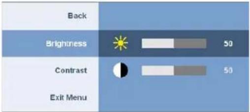 |
| Back | Pushto go back to the main menu. | |
| Brightness | Brightness adjusts the luminance of the backlight.Push thebutton to increase brightness and push thebutton to decrease brightness (min 0 ~ max 100). | |
| Contrast | Adjust Brightness first, and then adjust Contrast only if further adjustment is necessary.Push thebutton to increase contrast and push thebutton to decrease contrast (min 0 ~ max 100).The Contrast function adjusts the degree of difference between darkness and lightness on the monitor screen. | |
| Exit Menu | Pushto exit the OSD main menu. | |
 | AUTO ADJUST | Even though your computer recognizes your monitor on startup, the Auto Adjustment function optimizes the display settings for use with your particular setup.AUTO ADJUSTMENT IN PROGRESS....NOTE: In most cases, Auto Adjust produces the best image for your configuration.NOTE: AUTO ADJUST option is only available when you are using the analog (VGA) connector. |
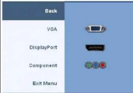
 | INPUT SOURCE | Use the INPUT SOURCE menu to select between different video signals that may be connected to your monitor. |
| Back | ||
| Auto Select | Scan for Input Sources | |
| VGA | ||
| DVI-D1 | ||
| DVI-D2 | ||
| DisplayPort | ||
| HDMI | ||
| Component | ||
| S-Video | ||
| Composite | ||
| Exit Menu | ||
| Back | Push to go back to the main menu. | |
| Auto Select | Push to scan for available input signals. | |
| VGA | Select VGA input when you are using the analog (VGA) connector. Push to select the VGA input source. | |
| DVI-D1/DVI-D2 | Select DVI-D input when you are using the Digital (DVI) connector. Push to select the DVI input source. | |
| DisplayPort | Select DisplayPort input when you are using DisplayPort connector. Push to select the DisplayPort input source. | |
| HDMI | Select HDMI input when you are using HDMI connector. Push to select the HDMI input source. | |
| Component | Select Component input when you are using component video connector. Push to select the component input source. | |
| S-Video | Select S-Video input when you are using S-Video connector. Push to select the S-Video input source. | |
| Composite | Select Composite input when you are using composite video connector. Push to select the composite input source. | |
| Exit Menu | Push to exit the OSD main menu. | |
| PRESET MODES | Use the Preset Modes to adjust the color setting mode and color temperature.There are different color setting sub-menus for VGA/DVI-D and Video input. | |
| Color setting submenu for VGA/DVI-D input | BackInput Color Format | RGB | YPbPr | BackInput Color Format | RGB | YPbPr |
| Gamma | PC | MAC | Gamma | PC | MAC | |
| Color setting submenu for Video Input | Color Setting Mode | Graphics | Video | Color Setting Mode | Graphics | Video |
| Presel Modes | Desktop | Presal Modes | Movie | |||
| Multimedia | Game | |||||
| Game | Sports | |||||
| Adobe RGB | Nature | |||||
| sRGB | 50 | |||||
| Warm | 50 | |||||
| Cool | 50 | |||||
| Custom (R,G,B) | Reset to Default Color Settings | |||||
| Exit Menu | Exit Menu | |||||
| VGA/DVI-D input | Video input | |||||
| Back | Push to go back to the main menu. | |||||
| Input Color Format | Choose the RGB option if monitor is connected to a PC or a DVD using a VGA or a DVI cable. Choose the YPbPr option if monitor is connected to a DVD by a YPbPr cable. | |||||
| Gamma | To achieve the different color mode for PC and Mac. | |||||
| Color Setting mode | You can choose between a Graphics and a Video mode. If your computer is connected to your monitor, choose Graphics. If a DVD, STB, or VCR is connected to your monitor, choose Video. | |||||
| Preset Modes (VGA/DVI-D input) | You can choose different color presets for different viewing modes. | |||||
| Desktop | Mode suitable for desktop applications. | |||||
| Multimedia | Mode for multimedia applications (example, video playback). | |||||
| Game | Mode suitable for game applications. | |||||
| Adobe RGB | This mode is compatible with Adobe RGB (1998). | |||||
| sRGB | Mode to emulate 72% NTSC color. | |||||
| Warm | Warm mode is selected to obtain a redder tint. This color setting is typically used for color-intensive applications (photograph image editing, multimedia, movies, etc.). | |||||
| Cool | Cool mode is selected to obtain a bluish tint. This color setting is typically used for text based applications (spreadsheets, programming, text editors, etc.). | |||||
| Custom (R,G,B) | Use the button to increase or decrease each of the three colors (R, G, B) independently, in single-digit increments, from 0 t 100. | |||||
| Preset Modes (Video input) | You can choose different color presets for different viewing modes. | |||||
| Movie | Mode suitable for movie playback. | |||||
| Game | Mode suitable for game applications. | |||||
| Sports | Mode suitable for sports scenes. | |||||
| Nature | Mode suitable for nature scenes. | |||||
 | Hue | This feature can make color shift of video image to green or purple. This is used to adjust for desired flesh tone color.Use and buttons to adjust the hue from '0' to '100'.makes video image shade into greenishmakes video image shade into purplishNOTE:Hue adjustment only available for video input. | ||||||
 | Saturation | This feature can adjust the color saturation of the video image.Use and buttons to adjust the saturation from '0' to '100'.makes video image looks more monochromemakes video image looks more colorfulNOTE:Saturation adjustment only available for video input. | ||||||
| Color Reset | Reset your monitor color settings to the factory settings. | |||||||
| Exit Menu | Push to exit the OSD main menu. | |||||||
 | DISPLAY SETTINGS | |||||||
| Display setting mode submenu for VGA/DVI-D input | BackWide Mode 1:1 Aspect FillHorizontal Position 50Vertical Position 50Sharpness 50Pixel Clock 50Phase 50Dynamic Contrast On OffDisplay Info. Display Monitor InformationDisplay Reset Reset to Default Display SettingsExit Menu | or | BackWide Mode 1:1 Aspect FillSharpness 50Dynamic Contrast On OffDisplay Info. Display Reset Exit Menu | |||||
| Display setting mode Video input | ||||||||
| VGA/DVI-D input Video inputNOTE:Display Settings modes are different between the VGA/DVI-D and Video inputs. | ||||||||
| Back | Push to go back to the main menu. | |||||||
| Wide Mode | Adjust the image ratio as 1:1, aspect or full screen. | |||||||
| Horizontal Position | Use the and buttons to adjust image left and right. Minimum is '0' (-). Maximum is '100' (+).NOTE:When using DVI source, the Horizontal Position setting is not available. | |||||||
| Vertical Position | Use the and buttons to adjust image up and down. Minimum is '0' (-). Maximum is '100' (+).NOTE:When using DVI source, the Vertical Position setting is not available. | |||||||
| Sharpness | This feature can make the image look sharper or softer.Use and buttons to adjust the sharpness from '0' to '100'. | |||||||
| Pixel Clock | The Pixel Clock and Phase adjustments allow you to adjust your monitor to your preference. These settings are accessed through the main OSD menu, by selecting 'Display Settings'.Use the and buttons to adjust for best image quality.If satisfactory results are not obtained using the Phase adjustment, use the Pixel Clock (coarse) adjustment and then use Phase (fine), again. | |||||||
| Phase | NOTE:Pixel Clock and Phase Adjustments are only available for "VGA" input. | |||||||
| Dynamic Contrast | The Dynamic Contrast adjustment helps get a higher contrast if you choose Game preset, Movie Preset, Sports Preset and Nature Preset. (Brightness control is disabled while in Dynamic Contrast mode and will be grayed out.)Use the button to enable the Dynamic Contrast adjustment.Use the button to disable the Dynamic Contrast adjustment. | |||||||
| Display Info | All the settings related to this monitor. | |||||||


Display Reset
Reset the image to the original factory setting.

Push to exit the OSD main menu.
Exit Menu
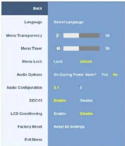
OTHER SETTINGS
Back
Push 📄 to go back to the main menu.
Language
Language option to set the OSD display to one of five languages (English, Espanol, Francais, Deutsch, or Japanese).
Menu
This function is used to adjust the OSD background from opaque to transparent.
Transparency
Menu Timer
OSD Hold Time: Sets the length of time the OSD will remain active after the last time you pressed a button.
Use the ⏻ and Ⓕ buttons to adjust the slider in 1 second increments, from 5 to 60 seconds.
Menu Lock
Controls user access to adjustments. When 'Lock' is selected, no user adjustments are allowed. All buttons are locked except button.
NOTE: When the OSD is locked, pressing the menu button will take the user directly to the OSD settings menu, with 'OSD Lock' pre-selected on entry. Press and hold 📄 button for 15 seconds to unlock and allow user access to all applicable settings.
Audio
To turn on or off audio power during power save mode.
Options
Default is "Enable". Select Disable to disable this feature.
Yes — Turn off audio power during power save mode.
No — Turn on audio power during power save mode.
Audio
Audio offers two kind of configurations of audio channels. Use the ⏻ or ⏻ button to move between 2 channels and 5.1 channels and and select the desired option.
Configuration
DDC/CI (Display Data Channel/Command Interface) allows your monitor parameters (brightness, color balance etc) to be adjustable via software on your PC. You can disable this feature by selecting "Disable".
DDC/CI
Default is "Enable". Select Disable to disable this feature.
Enable this feature for best user experience and optimum performance of your monitor.
Below warning message appears when you select "Enable DDC/CI";
The function of adjusting display setting using PC application will be disabled.
Disable DDC/CI function? -No Yes+
LCD
If an image appears to be stuck on the monitor, select LCD Conditioning to help eliminate any image retention. Using the LCD Conditioning feature may take several hours. Severe cases of image retention are known as burn-in, the LCD Conditioning feature does not remove burn-in.
Below warning message appears when you select "Enable LCD Conditioning":
This feature will help reduce minor cases of image retention.
Depending on the degree of image retention, the program may take some time to run.
Do you want to continue?
-No Yes+
Factory
NOTE: Use LCD Conditioning only when you experience a problem with image retention.
Reset all OSD settings to the factory preset values.

Reset
Exit Menu
Push to exit the OSD main menu.
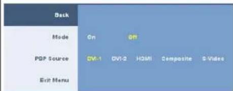
PBP
SETTINGS
This function brings up a window displaying image from another input source. Thus you can watch 2 images from different sources at the same time.
Picture by Picture (PBP) submenu when Picture by Picture (PBP) OFF
INPUT SOURCE submenu when Picture by Picture (PBP) ON (Main source is VGA or DisplayPort or Component input.)
Picture by Picture (PBP) submenu when Picture by Picture (PBP) ON (Second source is DVI or HDMI or Composite or S-Video.
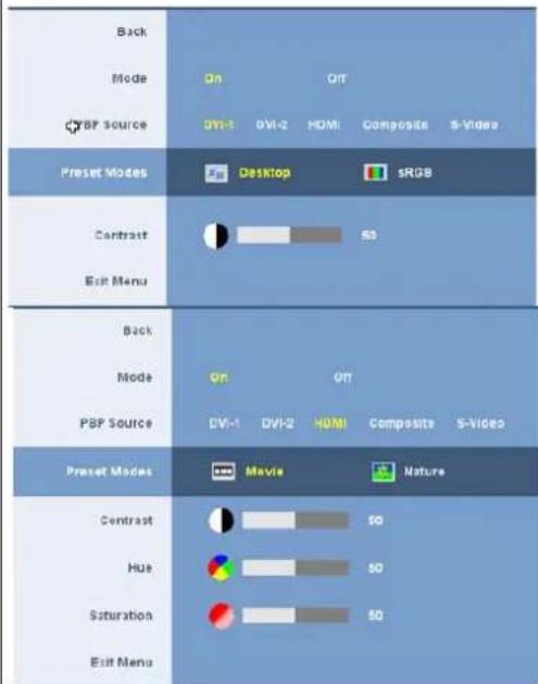
| BackModeOnOffPSP SourceDVI-1DVI-2HDMICompositeS-Video | |
| Preset ModeEMovieNatureContrast50Hue50Saturation50Exit Menu | |
| BackModeOnOffPBP SourceDVI-1DVI-2HDMICompositeS-Video | |
| Preset ModeEMovieNatureContrast50Hue50Saturation50Exit Menu | |
| NOTE: When using DVI source, the contrast adjustment is not available. | |
| Back | Pushto go back to the main menu. |
| Mode | Useandbuttons to browse andto select Picture by Picture (PBP) "On" or "Off". |
| PBP Source | Select an input signal for Picture by Picture (PBP). (DVI-1/DVI-2/HDMI/Composite/S-Video).Useandbuttons to browse andto select. |
| Preset Modes | You can choose different color presets for different viewing modes.Desktop mode is for desktop applications. (DVI input source only.)sRGB mode emulate 72% NTSC color. (DVI input source only.)Movie mode is suitable for movie playback. (Video input sources only. HDMI/Composite /S-Video )Nature mode is suitable for nature scenes. (Video input sources only, HDMI/Composite/S-Video )Useandbuttons to browse andto select |
| Contrast | Adjust the contrast level of the picture in Picture by Picture (PBP) Mode.button reduce the contrast.button increases the contrast. |
| NOTE: Contrast adjustment only available for video input. | |
| Hue | This function shifts the color of Picture by Picture (PBP) image to green or purple. This is used to adjust for desired flesh tone color.Useandbuttons to adjust the hue from '0' to '100'.makes video image shade into greenish.makes video image shade into purplish. |
| NOTE: Hue adjustment only available for video input. | |
| Saturation | Adjust the color saturation of Picture by Picture (PBP) image.Useandbuttons to adjust the saturation from '0' to '100'.button makes the image look more monochrome.button makes the image look more colorful. |
| NOTE: Saturation adjustment only available for video input. | |
| Exit Menu | Pushto exit the OSD main menu. |
OSD Warning Messagess
When the monitor does not support a particular resolution mode you will see the following message :

This means that the monitor cannot synchronize with the signal that it is receiving from the computer. See Monitor Specifications for the Horizontal and Vertical frequency ranges addressable by this monitor. For analog input, it is recommended to use the resolution 1920 x 1200. For digital input, it is recommended to use the resolution 2560 x 1600.
If you press any button other than the power button one of the following messages will appear depending on the selected input:
VGA/DVI-D input

In Picture by Picture (PBP) mode, when the monitor does not sense the selected signal input, one of the following messages will appear depending upon the selected input as long as the OSD screen is closed.
1. VGA
2. DVI-D 1 / DVI-D 2

3. DisplayPort

4. HDMI

5. S-Video

6. Composite

7. Component

If either VGA or DVI-D input is selected and both VGA and DVI-D cables are not connected, a floating dialog box as shown below appears.


NOTE: When the cable is connected back to the input of the monitor, any active Picture by Picture (PBP) window will disappear. Enter Picture by Picture (PB) submenu to bring back the Picture by Picture (PBP) window.
NOTE: The Picture by Picture (PBP) function can bring up a picture from a second image source. Thus you can watch images from 1 PC source (D-Sub or DVI Source (Composite or S-video or Component). The functions will not allow for 2 Video sources to perform Picture by Picture (PBP).
See Solving Problems for more information.
Setting the Optimal Resolution
NOTE: The optimal resolution is 1920 x 1200 for Analog input and 2560 x 1600 for Digital input.
To set the optimal resolution for the monitor:
Windows XP:
- Right-click on the desktop and select Properties.
- Select the Settings tab.
- Set the screen resolution to 1920 x 1200/2560 x 1600.
- Click OK
Windows Vista or Windows 7:
- Right-click on the desktop and select Personalization.
- Click Change Display Settings.
- Move the slider-bar to the right by pressing and holding left-mouse button and adjust the screen resolution to 1920 x 1200/2560 x 1600.
- Click OK.
If you do not see 1920 x 1200/2560 x 1600 as an option, you may need to update your graphics driver. Depending on your computer, complete one of the following procedures:
- If you have a Dell desktop or portable computer:
o Go to support.dell.com, enter your service tag, and download the latest driver for your graphics card. - If you are using a non-Dell computer (portable or desktop):
- Go to the support site for your computer and download the latest graphic drivers.
- Go to your graphics card website and download the latest graphic drivers.
Using the Dell Soundbar (Optional)
The Dell Soundbar is a stereo two channel system adaptable to mount on Dell Flat Panel Displays. The Soundbar has a rotary volume and on/off control to adjust the overall system level, a blue LED for power indication, and two audio headset jacks.
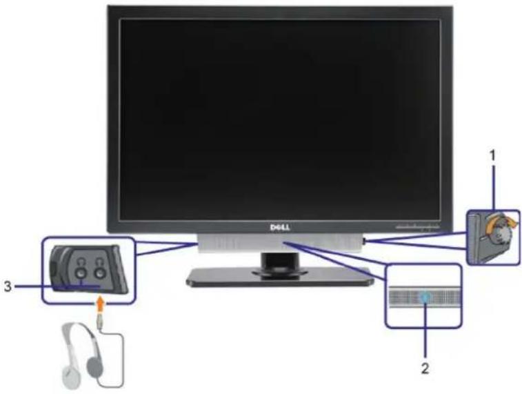
- Power/volume control
- Power indicator
- Headphone connectors
Using the Tilt, Swivel, and Vertical Extension
Tilt/Swivel
With the built-in stand, you can tilt and/or swivel the monitor for the most comfortable viewing angle.
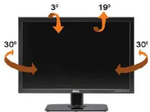

NOTE: The stand is attached and extended when the monitor is shipped from the factory.
Vertical Extension
The stand extends vertically up to 90mm. The figure below illustrates how to extend the stand vertically.
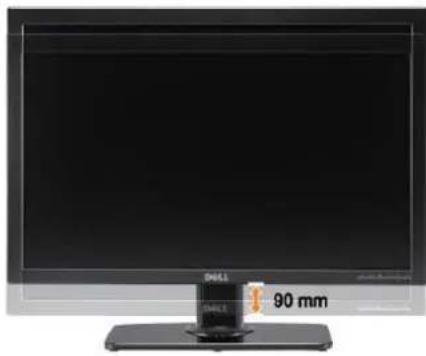
natural_image
Front view of a black desktop computer monitor with a 90 mm display and brand logo (no visible text or symbols on the screen)Back to Contents Page
Setting Up Your Monitor
Dell™ 3008WFP Flat Panel Monitor User's Guide
Important instructions to set the display resolution to 1920 x 1200 (VGA input source)/2560 x 1600(DVI/Displayport input sources) (Optimal)
For optimal display performance while using the Microsoft Windows® operating systems, set the display resolution to 1920 x 1200/2560 x 1600 pixels by performing the following steps:
In Windows XP:
-
Right-click on the desktop and click Properties.
-
Select the Settings tab.
-
Move the slider-bar to the right by pressing and holding left-mouse button and adjust the screen resolution to 1920 x 1200/2560 x 1600.
-
Click OK.
In Windows Vista ^® or Windows 7:
-
Right-click on the desktop and click Personalization.
-
Click Change Display Settings.
-
Move the slider-bar to the right by pressing and holding the left-mouse button and adjust the screen resolution to 1920 x 1200/2560 x 1600.
-
Click OK.
If you do not see 1920 x 1200/2560 x 1600 as an option, you may need to update your graphics driver. Please choose the scenario below that best describes the computer system you are using, and follow the provided directions:
1: If you have a Dell™ desktop or a Dell™ portable computer with internet access.
2: If you have non Dell™ desktop, portable computer, or graphic card.
Dell™ 3008WFP Flat Panel Monitor
User Guide
- Important instructions to set the display resolution to 1920 x 1200 (VGA input source)/2560 x 1600 (DVI/Displayport input sources) (Optimal)
Information in this document is subject to change without notice. © 2007-2009 Dell Inc. All rights reserved.
Reproduction in any manner whatsoever without the written permission of Dell Inc. is strictly forbidden.
Trademarks used in this text: Dell and the Dell logo are trademarks of Dell Inc; Microsoft, Windows, and Windows NT are registered trademarks of Microsoft Corporation;
Adobe is a trademark of Adobe Systems Incorporated, which may be registered in certain jurisdictions.
Other trademarks and trade names may be used in this document to refer to either the entities claiming the marks and names or their products. Dell Inc. disclaims any proprietary interest in trademarks and trade names other than its own.
Model 3008WFPt
December 2009 Rev. A05
Setting Up the Monitor
Dell™ 3008WFP Flat Panel Monitor User's Guide
Connecting the Monitor
Organizing Your Cables
- Attaching the Soundbar (optional)
Removing the Stand
Attaching the Stand
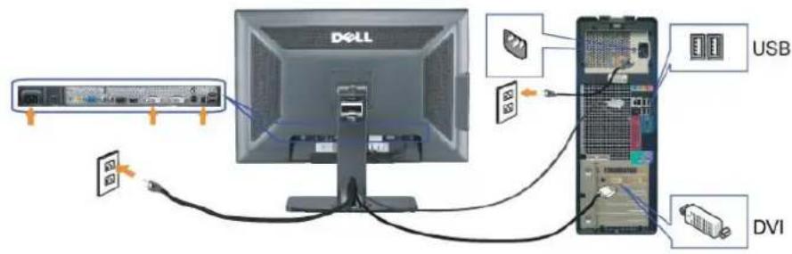
Connecting Your Monitor
CAUTION: Before you begin any of the procedures in this section, follow the Safety Instructions.
To connect your monitor to the computer perform the following steps/instructions:
• Turn off your computer and disconnect the power cable.
- Connect either the white (digital DVI-D) or the blue (analog VGA) display connector cable to the corresponding video port on the back of your computer. Do not use both cables on the same computer. Use both the cables only when they are connected to two different computers with appropriate video systems.
Connecting the white DVI cable
Connecting the blue VGA cable

Connecting the Displayport cable
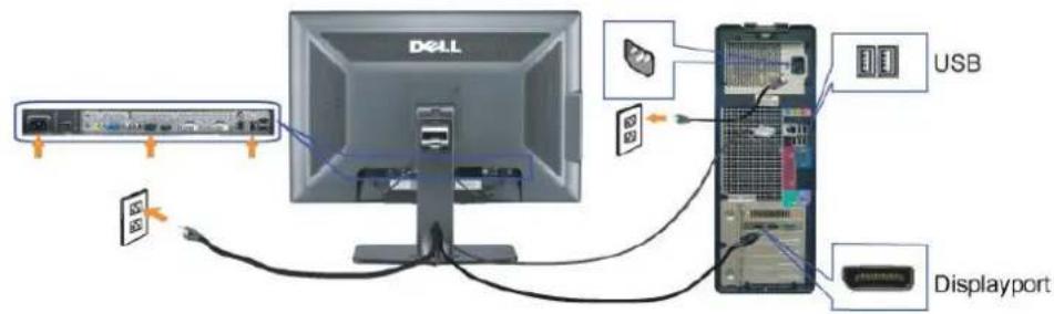

NOTE: The Graphics are used for the purpose of illustration only. Appearance of the computer may vary.
After you have completed connecting the DVI/VGA/DisplayPort cable, follow the procedure below to connect the USB cable to the computer and complete your monitor setup:
- Connect the upstream USB port (cable supplied) to an appropriate USB port on your computer.
- Connect USB peripherals to the downstream USB ports (rear or side) on the monitor. (See rear or side view for details.)
- Plug the power cables for your computer and monitor into a nearby outlet.
- Turn on the monitor and the computer.
If your monitor displays an image, installation is complete. If it does not display an image, see Solving Problems. - Use the cable holder on the monitor stand to organize the cables.
Organizing Your Cables
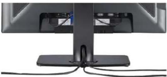
natural_image
Close-up of a computer monitor with visible cables and base mount (no text or symbols)After attaching all necessary cables to your monitor and computer, (See Connecting Your Monitor for cable attachment,) use the cable holder to organize all cables as shown above.
Attaching the Soundbar
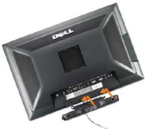
natural_image
Top-down view of a Dell monitor with attached cable and drive module (no visible text or symbols)
NOTICE: Do not use with any device other than Dell Soundbar.

NOTE: Soundbar Power Connector - 12V DC output is for optional Dell Soundbar only.
- Working from the rear of the monitor, attach Soundbar by aligning the two slots with the two tabs along the bottom rear of the monitor.
- Slide the Soundbar to the left until it snaps into place.
- Connect the Soundbar with the DC power connector.
- Insert the mini stereo plug from the rear of the Dell Soundbar into the computer's audio output jack.
NOTE: To playback audio from HDMI sources, insert the mini stereo plug into the audio OUT connector at the back of the monitor.

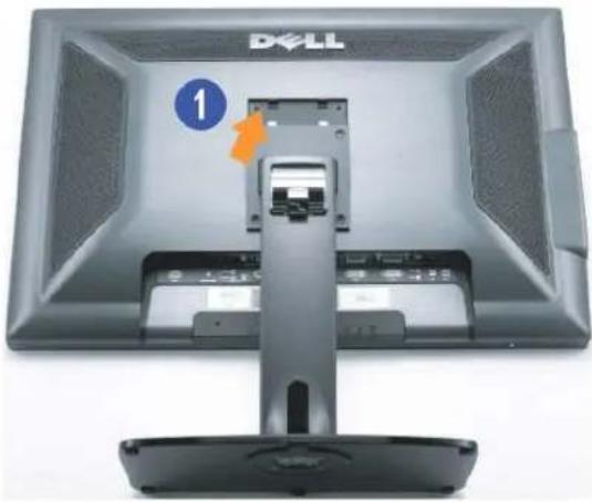
Removing the Stand

NOTE: To prevent scratches on the LCD screen while removing the stand, ensure that the monitor is placed on a clean surface.
Complete the following steps to remove the stand:
- Remove the four screws from the stand.
- Remove the stand by lifting it straight up and away from the monitor.
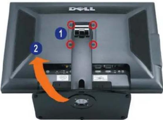
Attaching the Stand
natural_image
Top-down view of a Dell monitor with an orange arrow pointing to a component, showing no visible text or symbols on the screen itself.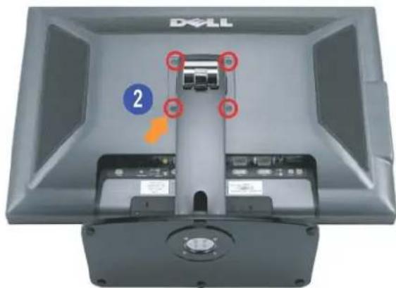
Place the stand on a flat surface and follow these steps to attach the monitor stand:
-
Fit the groove on the back of the monitor to the two tabs on the upper part of the stand.
-
Lower the monitor so that the monitor mounting area snaps on to or locks on to the stand and tighten up the bolts as indicated.
Back to Contents Page
Back to Contents Page
Solving Problems
Dell™ 3008WFP Flat Panel Monitor User's Guide
Monitor Specific Troubleshooting
Common Problems
Video Problems
Product Specific Problems
Universal Serial Bus Specific Problems
Troubleshooting the Dell™ Soundbar
Troubleshooting the Card Reader

CAUTION: Before you begin any of the procedures in this section, follow the Safety Instructions.
Monitor Specific Troubleshooting
Self-Test Feature Check
Your monitor provides a self-test feature that allows you to check whether your monitor is functioning properly. If your monitor and computer are properly connected but the monitor screen remains dark, run the monitor self-test by performing the following steps:
- Turn off both your computer and the monitor.
- Unplug the video cable from the back of the computer. To ensure proper Self-Test operation, remove both Digital (white connector) and the Analog (blue
connector) cables from the back of computer - Turn on the monitor.
The floating dialog box should appear on-screen (against a black background) if the monitor cannot sense a video signal and is working correctly. While in self-test mode, the power LED remains blue. Also, depending upon the selected input, one of the dialogs shown below will continuously scroll through the screen.

or

-
This box also appears during normal system operation if the video cable becomes disconnected or damaged.
-
Turn off your monitor and reconnect the video cable; then turn on both your computer and the monitor.
If your monitor screen remains blank after you use the previous procedure, check your video controller and computer, because your monitor is functioning properly.

NOTE: Self test feature check is not available for S-Video, Composite, and Component video modes.
Common Problems
The following table contains general information about common monitor problems you might encounter and the possible solutions.
| Common Symptoms | What You Experience | Possible Solutions |
| No Video/ Power LED off | No picture | Ensure that the video cable connecting the monitor and the computer is properly connected and secure.Verify that the power outlet is functioning properly using any other electrical equipment.Ensure that the power button depressed fully. |
| No Video/ Power LED on | No picture or no brightness | Increase brightness & contrast controls via OSD.Perform monitor self-test feature check.Check for bent or broken pins in the video cable connector.Ensure that the correct input source is selected via the Input Source Select button.Run the built-in diagnostics. |
| Poor Focus | Picture is fuzzy, blurry, or ghosting | Perform Auto Adjust via OSD.Adjust the Phase and Pixel Clock controls via OSD.Eliminate video extension cables.Reset the monitor to Factory Settings.Change the video resolution to the correct aspect ration (16:10). |
| Shaky/Jittery Video | Wavy picture or fine movement | Perform Auto Adjust via OSD.Adjust the Phase and Pixel Clock controls via OSD.Reset the monitor to Factory Settings.Check environmental factors.Relocate the monitor and test in another room. |
| Missing Pixels | LCD screen has | Cycle power on-off. |
Missing Pixels LCD screen has • Cycle power on-off.
| spots | • Pixel that is permanently off is a natural defect that can occur in LCD technology. | |
| Stuck-on Pixels | LCD screen has bright spots | • Cycle power on-off.• Pixel that is permanently off is a natural defect that can occur in LCD technology. |
| Brightness Problems | Picture too dim or too bright | • Reset the monitor to Factory Settings.• Auto Adjust via OSD.• Adjust brightness & contrast controls via OSD. |
| Geometric Distortion | Screen not centered correctly | • Reset the monitor to Factory Settings.• Auto Adjust via OSD.• Adjust brightness & contrast controls via OSD.NOTE: When using 'DVI-D', the positioning adjustments are not available. |
| Horizontal/Vertical Lines | Screen has one or more lines | • Reset the monitor to Factory Settings.• Perform Auto Adjust via OSD.• Adjust Phase and Pixel Clock controls via OSD.• Perform monitor self-test feature check and determine if these lines are also in self-test mode.• Check for bent or broken pins in the video cable connector.NOTE: When using 'DVI-D', the Pixel Clock and Phase adjustments are not available. |
| Synchronization Problems | Screen is scrambled or appears torn | • Reset the monitor to Factory Settings.• Perform Auto Adjust via OSD.• Adjust Phase and Pixel Clock controls via OSD.• Perform monitor self-test feature check to determine if scrambled screen appears in self-test mode.• Check for bent or broken pins in the video cable connector.• Restart the computer in the safe mode. |
| Safety Related Issues | Visible signs of smoke or sparks | • Do not perform any troubleshooting steps.• Contact Dell immediately. |
| Intermittent Problems | Monitor malfunctions on & off | • Ensure that the video cable connecting the monitor to the computer is connected properly and is secure.• Reset the monitor to Factory Settings.• Perform monitor self-test feature check to determine if the intermittent problem occurs in self-test mode. |
| Missing Color | Picture missing color | • Perform monitor self-test feature check.• Ensure that the video cable connecting the monitor to the computer is connected properly and is secure.• Check for bent or broken pins in the video cable connector.. |
| Wrong Color | Image is displayed with the wrong colors. | • Change the Color Setting Mode to Graphics or Video using the OSD.• Try different Color Preset Settings in Color Settings OSD.• Adjust R/G/B value in Color Settings OSD if the Color Management is turned off.• Change the Input Color Format to PC RGB or YPbPr in the Advance Setting OSD. |
| Image retention from a static image left on the monitor for a long period of time | Faint shadow from the static image displayed appears on the screen | • Use the Power Management feature to turn off the monitor at all times when not in use (for more information, seePower Management Modes).• In OSD Menu, under OTHER SETTINGS, selectEnable LCD Conditioning. Using this option may take several hours before the image is eliminated.• Alternatively, use a dynamically changing screensaver. |
Video Problems
| Common Symptoms | What You Experience | Possible Solutions |
| No Video | No signal indicator is displayed | Check Video Input Selection.Composite: Yellow colored RCA jack.S-Video: Typically a round 4 pin jack.Component: Red, Blue, Green colored RCA jacks. |
| Low Quality DVD playback | Picture not crisp and some color distortion | Check DVD connection and use the best available video cable.Composite gives good picture.S-Video gives better picture.Component gives the best picture. |
| Blinking Video | Video is blinking or discontinuous | Check DVD connection and use the best available video cable.Composite gives good picture.S-Video gives better picture.Component gives the best picture.Check if DVD player is HDCP compliant.Some non-compliant players may exhibit blinking video and others will di a raster screen (image larger or smaller than the screen). |

NOTE: When choosing S-Video, Composite or Component video, Auto Adjust function is not available.
Product Specific Problems
| Common Symptoms | What You Experience | Possible Solutions |
| Screen image is too small | Image is centered on screen, but does not fill entire viewing area | Check the Scaling Ratio setting in Image Setting OSDReset the monitor to Factory Settings. |
| Cannot adjust the monitor with the buttons on the front panel | OSD does not appear on the screen | Turn off the monitor, unplug the power cord, plug back, and then turn on the monitor. |
| The monitor will not go into power saving mode. | No picture, the LED light is blue. When press "+" or "Menu" key, the message " No S-Video input signal ", " No Composite input signal " or " No Component input signal " appears | Move mouse or hit any key on the keyboard or activate the video player, then access the OSD to set Audio to off state. |
| No Input Signal when user controls are pressed | No picture, the LED light is blue. When press +, - or Menu key, the message No S-Video input signal, No Composite input signal, or No Component input signal appears | Check the signal source. Ensure the Computer is not in the power saving mode by moving the mouse or pressing any key on the keyboard.Check to make sure Video Source to S-Video, Composite or Component is powered and playing video media.Check whether the signal cable is plugged in properly. Re-plug the signal cable if necessary.Reset the computer or video player. |
| The picture does not fill the entire screen. | The picture cannot fill the height or width of the screen | Due to different video formats (aspect ratio) of DVDs, the monitor may display in full screen. |

NOTE: When choosing DVI-D mode, the Auto Adjust function is not available.
Universal Serial Bus (USB) Specific Problems
| Common Symptoms | What You Experience | Possible Solutions |
| USB interface is not working | USB peripherals are not working | Check that your monitor is turned ON.Reconnect the upstream cable to your computer.Reconnect the USB peripherals (downstream connector).Switch off and then turn on the monitor again.Reboot the computer.Some USB devices like external portable HDD require higher electric current; connect the device directly to the computer system. |
| High Speed USB 2.0 interface is slow. | High Speed USB 2.0 peripherals working slowly or not working at all | Check that your computer is USB 2.0-capable.Some computers have both USB 2.0 and USB 1.1 ports. Ensure that the correct USB port is used.Reconnect the upstream cable to your computer.Reconnect the USB peripherals (downstream connector).Reboot the computer. |
Troubleshooting the Dell™ Soundbar
| Common Symptoms | What You Experience | Possible Solutions |
| No Sound | No power to Soundbar - the power indicator is off (built-in DC power supply. i.e. 3008WFP) | Turn the Power/Volume knob on the Soundbar clockwise to the middle position; check if the power indicator (green LED) on the front of the Soundbar is illuminated.Ensure that the power cable from the Soundbar is plugged into the monitor.Ensure that the monitor has power.If the monitor has no power, seeMonitor Specific Troubleshootingfor monitor common problem. |
| No Sound | Soundbar has power - power indicator is on | Plug the audio line-in cable into the computer's audio out jack.Set all volume controls to their maximum and ensure that the mute option is not enabled.Play some audio content on the computer (example, audio CD, or MP3).Turn the Power/Volume knob on the Soundbar clockwise to a higher volume setting.Clean and reseat the audio line-in plug.Test the Soundbar using another audio source (For example: portable CD player, MP3 player). |
| Distorted Sound | Computer's sound card is used as the audio source | Clear any obstructions between the Soundbar and the user.Confirm that the audio line-in plug is completely inserted into the jack of the sound card.Set all Windows volume controls to their midpoints.Decrease the volume of the audio application.Turn the Power/Volume knob on the Soundbar counter-clockwise to a lower volume setting.Clean and reseat the audio line-in plug.Troubleshoot the computer's sound card.Test the Soundbar using another audio source (For example: portable CD player, MP3 player).Avoid using an audio cable extension or audio jack converter. |
| Distorted Sound | Other audio source is used | Clear any obstructions between the Soundbar and the user.Confirm that the audio line-in plug is completely inserted into the jack of the audio source.Decrease the volume of the audio source.Turn the Power/Volume knob on the Soundbar counter-clockwise to a lower volume setting.Clean and reseat the audio line-in plug. |
| Unbalanced Sound Output | Sound from only one side of Soundbar | Clear any obstructions between the Soundbar and the user.Confirm that the audio line-in plug is completely inserted into the jack of the sound card or audio source.Set all Windows audio balance controls (L-R) to their midpoints.Clean and reseat the audio line-in plug.Troubleshoot the computer's sound card.Test the Soundbar using another audio source (For example: portable CD player, MP3 player). |
| Low Volume | Volume is too low | Clear any obstructions between the Soundbar and the user.Turn the Power/Volume knob on the Soundbar clockwise to the maximum volume setting.Set all Windows volume controls to their maximum.Increase the volume of the audio application.Test the Soundbar using another audio source (For example: portable CD player, MP3 player). |
Troubleshooting the Card Reader
NOTICE: Do not remove the media while the Card reader is reading or writing to the media. Doing so may cause loss of data or malfunction in the media.
| Common Symptoms | What You Experience | Possible Solutions |
| Drive letter is not assigned (Microsoft Windows XPTM only) | Conflict with network drive letter | Right-click My Computer on the desktop, and then click Manage. Under Computer Management, click Disk Management.In the list of drives in the right panel, right-click Removable Device and then click Change Drive Letter and Paths.Click Change, and in the drop-down box, specify a drive letter for the Removable Device, choose one that is not assigned to a mapped network drive.Click OK, and then click OK again. |
| Drive letter is assigned, but the media is not accessible | The media needs reformatting | Right-click the drive in Explorer and choose Format from the resulting menu.NOTICE: Formatting the media erases the contents.Test the card reader using another media or test the media on another card reader to ensure the media is not defective. |
| The media is removed during writing or erasing. | Computer prompts this error message during erasing.Error copying file or folder ORCannot write folder (folder name) or file (file name), during writing, or, Cannot remove folder (folder name) or file (file name) | Reinsert the media and write or erase again.While erasing, you cannot write or erase in the same folder or file name.The media may be corrupted, format the media and try again.NOTICE: Formatting the media erases the contents. |
| The media is removed while the LED is still blinking although the write/delete status window has disappeared. | Although the write/delete status window disappears, the writing/deleting action on the media may not have been completed if the LED is blinking. | Reinsert the media and write or erase again.The media may be corrupted, format the media and try again.NOTICE: Formatting the media erases the contents. |
| Cannot format or write on the media. | Write-protect switch is enabled | Verify that the write-protect switch of the media is unlocked. |
Back to Contents Page

- Dell™ 3008WFP Flat Panel Monitor User's Guide
- About Your Monitor
- Setting Up the Monitor
- Operating the Monitor
- Solving Problems
- Appendix
- Notes, Notices, and Cautions
- Product Features
- Identifying Parts and Features
- Label Description
- Monitor Specifications
- Power Management Modes
- Pin Assignments
- Universal Serial Bus (USB) Interface
- USB Upstream Connector
- USB Downstream Connector
- USB Ports
- Plug and Play Capability
- Card Reader Specifications
- Overview
- Features
- CAUTION: Safety Instructions
- FCC Notices (U.S. Only) and Other Regulatory Information
- Contacting Dell
- Setting Up Your Monitor
- If you have a Dell™ desktop or a Dell™ portable computer with internet access
- If you have non Dell™ desktop, portable computer, or graphic card
- Using the Front Panel
- Using the On-Screen Display (OSD) Menu
- Accessing the Menu System
- Main Menu for Analog (VGA) Input
- Main Menu for non Analog (non VGA) Input
- OTHER SETTINGS
- OSD Warning Messagess
- VGA
- DVI-D 1 / DVI-D 2
- DisplayPort
- HDMI
- S-Video
- Composite
- Component
- Setting the Optimal Resolution
- Using the Dell Soundbar (Optional)
- Using the Tilt, Swivel, and Vertical Extension
- Tilt/Swivel
- Vertical Extension
- Important instructions to set the display resolution to 1920 x 1200 (VGA input source)/2560 x 1600(DVI/Displayport input sources) (Optimal)
- Dell™ 3008WFP Flat Panel Monitor
- User Guide
- Connecting Your Monitor
- Organizing Your Cables
- Attaching the Soundbar
- Removing the Stand
- Attaching the Stand
- Monitor Specific Troubleshooting
- Self-Test Feature Check
- Common Problems
- Troubleshooting the Card Reader
Marque : DELL
Modèle : 3008WFP
Catégorie : Téléviseur