
Matrix Audio DX1616 - Processeur RCF - Notice d'utilisation et mode d'emploi gratuit
Retrouvez gratuitement la notice de l'appareil Matrix Audio DX1616 RCF au format PDF.

| Type de produit | Processeur audio matriciel numérique 16x16 |
| Marque | RCF |
| Modèle | Matrix Audio DX1616 |
| Architecture DSP | Hybride, 48 kHz, 40 bits virgule flottante |
| Nombre d'entrées/sorties analogiques | 16 entrées Mic/Ligne (commutables), 16 sorties ligne (connecteurs Euro 3,5 mm) |
| Entrées/sorties AES/EBU | 8 entrées + 8 sorties |
| Réseau audio Dante | 2 ports RJ45 (16x16 canaux, redondance) |
| Connectivité de contrôle | Ethernet RJ45 (TCP/IP), logiciel Solaro Console et application Solaro Control |
| Latence maximale | 3 ms |
| Écran et indicateurs | LED de statut (alimentation, réseau), LED par entrée/sortie (signal, clip) |
| Alimentation | 100-240 VAC, 50/60 Hz, avec interrupteur et fusible |
| Consommation électrique | Environ 50 W (estimation) |
| Dimensions (L x P x H) | 483 x 250 x 44 mm (19 pouces, 1U) |
| Poids | Environ 5 kg |
| Système d'exploitation requis | Windows 7/8/10, macOS (Intel), iOS/iPadOS pour l'application de contrôle |
| Configuration minimale PC | Processeur 1 GHz, 4 Go RAM, 500 Mo disque dur, écran 1920x1080 recommandé |
| Fonctions DSP principales | Routing matriciel, EQ paramétrique (4 bandes), filtres passe-haut/passe-bas (jusqu'à 24 dB/oct), délai (jusqu'à 500 ms, 1000 ms sur modules Delay/Aux), compresseur, filtre tout-pass, inversion de polarité |
| Préréglages (presets) | Préréglages usine et utilisateur, chargeables via le panneau de contrôle |
| Mise à jour du firmware | Via le logiciel Solaro Console, nécessite une connexion Ethernet |
| Sécurité | Ne pas exposer à l'eau, débrancher pendant les orages, maintenance par personnel qualifié |
| Nettoyage | Débrancher avant nettoyage, utiliser un chiffon sec |
| Température de fonctionnement | 0°C à 40°C (estimation) |
FOIRE AUX QUESTIONS - Matrix Audio DX1616 RCF
- Pas de DHCP disponible et adresse IP non définie manuellement
- Conflit d'adresse IP (plusieurs appareils avec la même IP)
- Incompatibilité de firmware
Questions des utilisateurs sur Matrix Audio DX1616 RCF
0 question sur cet appareil. Repondez a celles que vous connaissez ou posez la votre.
Poser une nouvelle question sur cet appareil
Téléchargez la notice de votre Processeur au format PDF gratuitement ! Retrouvez votre notice Matrix Audio DX1616 - RCF et reprennez votre appareil électronique en main. Sur cette page sont publiés tous les documents nécessaires à l'utilisation de votre appareil Matrix Audio DX1616 de la marque RCF.
MODE D'EMPLOI Matrix Audio DX1616 RCF
DX1616 User Manual
• Hybrid architecture DSP
• 48 KHz sampling, 40 bit floating point engine
- 16 x 16 I/O matrix
• Dante enabled network audio transport
• 8 AES/EBU inputs - 8 AES/EBU outputs
• Ethernet connectivity and control
• Maximum latency 3 ms
• Easy to use software GUI
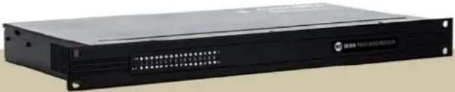
natural_image
Exterior view of a black server rack unit (no visible text or symbols)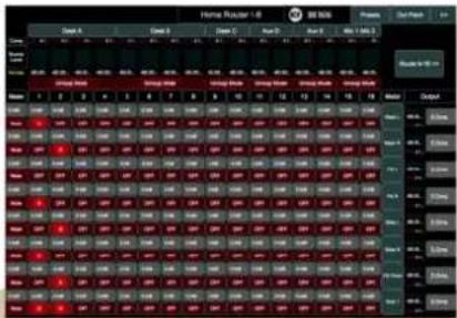
bar
Figure 10 - Bar Chart | Category | Value | |---|---| | Model A | 67.5 | | Model B | 68.2 | | Model C | 69.1 | | Model D | 70.3 | | Model E | 71.4 | | Model F | 72.5 | | Model G | 73.6 | | Model H | 74.7 | | Model I | 75.8 | | Model J | 76.9 | | Model K | 78.0 | | Model L | 79.1 | | Model M | 80.2 | | Model N | 81.3 | | Model O | 82.4 | | Model P | 83.5 | | Model Q | 84.6 | | Model R | 85.7 | | Model S | 86.8 | | Model T | 87.9 | | Model U | 89.0 | | Model V | 90.1 | | Model W | 91.2 | | Model X | 92.3 | | Model Y | 93.4 | | Model Z | 94.5 | | Model AA | 95.6 | | Model AB | 96.7 | | Model AC | 97.8 | | Model AD | 98.9 | | Model AE | 100.0 | | Model AF | 101.1 | | Model AG | 102.2 | | Model AH | 103.3 | | Model AI | 104.4 | | Model AJ | 105.5 | | Model AK | 106.6 | | Model AL | 107.7 | | Model AM | 108.8 | | Model AN | 109.9 | | Model AO | 110.0 | | Model AP | 111.1 | | Model AQ | 112.2 | | Model AR | 113.3 | | Model AS | 114.4 | | Model AT | 115.5 | | Model AU | 116.6 | | Model AV | 117.7 | | Model AW | 118.8 | | Model AX | 119.9 | | Model AY | 120.0 | | Model AZ | 121.1 | | Model BA | 122.2 | | Model BB | 123.3 | | Model BC | 124.4 | | Model BD | 125.5 | | Model BE | 126.6 | | Model BF | 127.7 | | Model BG | 128.8 | | Model BH | 129.9 | | Model BI | 130.0 | | Model BJ | 131.1 | | Model BK | 132.2 | | Model BL | 133.3 | | Model BM | 134.4 | | Model BN | 135.5 | | Model BO | 136.6 | | Model BP | 137.7 | | Model BPB | 138.8 | | Model BPB+BA | 139.9 | | Model BPB+BB | 140.0 | | Model BPB-BA+BA | 141.1 | | Model BPB-BA+BB+BA | 142.2 | | Model BPB-BA+BB+BA+BA+BA+BA+BA+BA+BA+BA+BA+BA+BA+BA+BA+BA+BA+BA+BA+BA+BA+BA+BA+BA+BA+BA+BA+BA+BA+BA+BA+BA+BA+BA+BA+BA+BA+BA+BA+BA+BA+BA+BA+BA+BA+BA+BA+BA+BA+BA+BA+BA+Table of content
QUICK START GUIDE 5
WHAT'S IN THE BOX 5
WHAT YOU NEED TO PROVIDE 5
SAFETY INFORMATION 5
INTRODUCTION AND DESCRIPTION 6
FRONT PANEL 6
REAR PANEL 6
INSTALL THE SOLARO CONSOLE & CONTROL SOFTWARE 7
FIREWALL - ALLOW ACCESS! 7
DOWNLOAD AND SAVE DX1616 PROJECT FILES 7
INITIAL DEVICE CONNECTIVITY 8
A DHCP ENABLED ROUTER, SERVER, OR ROUTER/SWITCH 8
A NON-DHCP ENABLED DIRECT CONNECTION OR INDIRECTLY VIA AN ETHERNET SWITCH. 8
A SINGLE PROCESSOR OR DEVICE IN THE NETWORK ONLY - NO DHCP AVAILABLE 8
IP RESET PUSH BUTTON / RESET PROCESSOR NETWORK SETTINGS (DHCP NOT AVAILABLE) 8
IP RESET WITH SOFTWARE 9
MULTIPLE PROCESSOR DEVICES CONNECTED TO THE NETWORK - NO DHCP AVAILABLE 9
DX1616 CONNECTED AND POWERED UP 9
LAUNCH THE SOLARO CONSOLE SOFTWARE 10
NETWORK VIEW 10
NETWORK CONNECTION INDICATORS 10
TCP/IP CONNECTION TROUBLE SHOOTING 11
THE THREE MOST COMMON REASONS FOR THIS YELLOW CONNECTION INDICATOR IS THE RESULT OF 11
SOLUTIONS 11
A FEW MESSAGE AND SOLUTION EXAMPLES BELOW. 11
MANUAL ASSIGNMENT OF IP ADDRESSES TO MULTIPLE DEVICES - NO DHCP: 11
A STATIC IP ADDRESS FOR YOUR COMPUTER - MULTIPLE DEVICES - NO DHCP: 12
FIRMWARE UPDATE TO DX 1616 PROCESSOR 12
SETTING UP SOLARO CONSOLE & CONTROL SOFTWARE 14
OPEN PROJECT (PROJECT FILE) 14
SAVE PROJECT FILE ON THE COMPUTER 14
LAUNCH DX1616 CONTROL SOFTWARE 14
MAP PHYSICAL DEVICES - DX1616 AND CONTROL PANEL 15
WARNING DETECTED, DEVICE "XXXX" NOT MAPPED 16
SWITCH TO ONLINE MODE: (TRANSFER/SAVE DSP DESIGN PROJECT TO DX1616) 16
SWITCH BACK TO DESIGN MODE (OFFLINE MODE) 18
OPERATING DX1616 18
RECOMMENDED OPERATING WITH SOLARO CONSOLE AND CONTROL 18
SOLARO CONTROL SETTINGS 19
HOME SCREEN (ROUTER 1-8) 19
HOME SCREEN (ROUTER 9-16) 20
INPUT SECTION DESK A, B 20
INPUT EQS 21
| INPUT SOURCE COMPENSATION 22 | |
| INPUT SECTION DESK C, AUX D, AUX E | 22 |
| INPUT SECTION MIC 1&2 | 23 |
| DSP MODULES OUTPUT SECTION | 23 |
| ANALOG/ AES OUTPUT PATCH | 25 |
| DANTE OUTPUT PATCH | 26 |
| PRESETS & RESETS | 26 |
| SOLAROCONSOLE - WITHOUT SOLARO CONTROL APP IN COMBINATION WITH A PROJECT (*.PJXML) FILE26 | |
| SOLARO CONSOLE - WITHOUT SOLARO CONTROL AND WITHOUT PROJECT FILE | 28 |
FAQS 30
| WHICH ARE THE “SYNC” OPTIONS WHEN CONNECTING TO DX1616? | 30 |
| SYNC FROM PC TO DX1616 | 30 |
| SYNC FROM DX1616 TO PC | 30 |
| WHAT HAPPENS WITH MY LAST SETTINGS IN DX1616 WHEN POWER IS SWITCHED OFF? | 31 |
| STAND BY OF REMOTE COMPUTER OR NETWORK INTERRUPTION | 31 |
| CAN I OPERATE THE DX1616 WITH SOLARO CONTROL APP ONLY? | 32 |
| HOW CAN I SAFE MY SETTINGS? | 32 |
| CAN I USE A SECOND CONTROL DEVICES TO MANAGE DX1616? | 32 |
| HOW CAN I CREATE A (USER) PRESET? | 33 |
| HOW CAN I EDIT AND SAVE A PRESET? | 37 |
TECHNICAL DATA 38
Table of figures
Fig.: 1: Solaro "Network View" – Devices are ON 9
Fig.: 2:Device Setup - Network IP Addresses and DHCP 9
Fig.: 3: Solaro Console start up window 10
Fig.: 4: Solaro Console "Network View" 10
Fig.: 5: DX1616 Firmware update – starting the process 13
Fig.: 6: Firmware update in process – Loading and verifying firmware 13
Fig.: 7: Firmware update in process – Do not power off the device 13
Fig.: 8: Firmware update - device not ready is shown 13
Fig.: 9: Firmware update – process is finished 14
Fig.: 10: Open project file 14
Fig.: 11: Solaro Control – selecting network interface 15
Fig.: 12: "This Control Panel has not been configured yet" 15
Fig.: 13: Mapping devices 15
Fig.: 14: Warning detected - Device not mapped 16
Fig.: 15: Load Design to Devices 16
Fig.: 16: Online mode startup window 17
Fig.: 17: Update device with project settings 17
Fig.: 18: Preparing devices to online control message 17
Fig.: 19: "Go back to Design Mode" – switching to Offline 18
Fig.: 20: Copying settings to project file – yes ore not 18
Fig.: 21: Solaro Control settings 19
Fig.: 22: Home Screen 20
Fig.: 23: Home Screen (Router 9-16) 20
Fig.: 24: Home Screen Inputs 21
Fig.: 25: Input sources 1-4 (Desk A) and Source Processing 21
Fig.: 26: Quick navigation << and >> through the source inputs 21
Fig.: 27: Source EQ - LS, PEQ, HS 22
Fig.: 28: Info menu about "source compensation" 22
Fig.: 29: Input section "Desk C, Aux D, Aux E" 23
Fig.: 30: Input section Mic 1&2 (Source 15 and 16) 23
Fig.: 31: Example of DSP module "Main L" 24
Fig.: 32: Quick navigation << and >> through the DSP modules 24
Fig.: 33: DSP module with All-Pass Filter 24
Fig.: 34: Analog/ AES output patch 25
Fig.: 35: Default output patch - help file 25
Fig.: 36: Fixed Dante output patch 26
Fig.: 37: Presets 26
Fig.: 38: "Online Control" with opened "Control" window 27
Fig.: 39: "Online Control" control panels and left menu 28
Fig.: 40: Solaro Console "Network View" 28
Fig.: 41: "Open Device" in "Network View" – the DSP schematics 29
Fig.: 42: "Open Device" - DSP windows and its settings 29
Fig.: 43: "Load Design to Devices" button 30
Fig.: 44: Syncing from PC to DX1616 30
Fig.: 45: Update devices with project settings 31
Fig.: 46: Control is shown "OFF" after stand by or in stand by of Control App 31
Fig.: 47: Control App re-syncing process 31
Fig.: 48: Creating a second "Control" device 32
Fig.: 49: Switching back to Design Mode - Copying parameters to project file 33
Fig.: 50: "Design Mode" - project view 34
Fig.: 51: "Design Mode" – Save Module Values to Preset 34
Fig.: 52: "Design Mode" - project view 35
Fig.: 53: Reserved area to put user presets 35
Fig.: 54: Drag and drop presets from component library to a control panel 35
Fig.: 55: Control panel – Edit presets button 36
Fig.: 56: Control panel - Edit preset button 36
Fig.: 57: "Design Mode" – Save Project As 36
Quick Start Guide
The Quick Start Guide is a separate document witch gives a short step by step instruction of DX1616.
What's in the Box
• The DX1616 processor
• USB drive with Software, Project File, Quick Start Guide
• IEC socket detachable power cable
• Detachable 3.5mm Euro terminal block connectors
What you need to provide
• A Windows PC - 1GHz or higher processor
• Windows 10, 8 or 7 OS
• An Apple computer (Intel) with OSX operating system
• 500 MB of free storage space
• 16 Bit or higher colors
- 4GB RAM minimum
• Network (Ethernet) interface
• Ethernet cable (Cat5 or 6)
Safety information
- READ THESE INSTRUCTIONS All the safety and operating instructions should be read before the product is operated.
- KEEP THESE INSTRUCTIONS The safety and operating instructions should be retained for future reference.
- HEED ALL WARNINGS All warnings on the product and in the operating instructions should be adhered to.
- FOLLOW ALL INSTRUCTIONS All operating and use of instructions should be followed.
- DO NOT USE THIS APPARATUS NEAR WATER Do not use the product near water. For example, near a bathtub, washbowl, kitchen sink, or laundry tub, in a wet basement, or near a swimming pool, and the like.
- CLEAN ONLY WITH DRY CLOTH Unplug the unit from the wall outlet before cleaning
- DO NOT BLOCK ANY VENTILATION OPENINGS Slots and openings in the cabinet back or bottom are provided for ventilation, to ensure reliable operation of the limit and to protect it from overheating. These openings must not be blocked or covered. The openings should never be blocked by placing the product on a bed, sofa, rug, or similar surface. This product should never be placed near or over a radiator or heat source. This product should not be placed in a built-in installation such as a bookcase or rack unless proper ventilation is provided or the manufacturer's instructions have been adhered to.
- DO NOT INSTALL NEAR ANY HEAT SOURCES This Product should be situated away from heat sources such as radiators, stoves, or other products (including amplifiers) that produces heat.
- DO NOT DEFEAT THE SAFETY PURPOSE OF THE POLARIZED OR GROUNDING-TYPE PLUG A Polarized plug has two blades with one wider than the other. A grounding-type plug has two blades and a third grounding prong. The wide blade or the third prongs are provided for your safety. If the provided plug does not fit into your outlet, consult an electrician for replacement of the obsolete outlet.
- PROTECT THE POWER CORD FROM BEING WALKED ON OR PINCHED PARTICULARLY AT PLUGS, CONVENIENCE RECEPTACLES, AND THE POINT WHERE THEY EXIT FROM THE APPARATUS.
- ONLY USE ATTACHMENTS/ACCESSORIES SPECIFIED BY THE MANUFACTURER.
-
USE ONLY WITH CART, STAND, TRIPOD, BRACKET, OR TABLE SPECIFIED BY THE MANUFACTURER, OR SOLD WITH THE APPARATUS. WHEN A CART IS USED, USE CAUTION WHEN MOVING THE CART/APPARATUS TO AVOID INJURY FROM TIP-OVER. Do not place this unit on an unstable cart, stand, tripod, bracket, or table. The unit may fall, causing serious injury to someone, and serious damage to the appliance. A unit and cart combination should be moved with care. Quick stops, excessive force, and uneven surfaces may cause the product and cart combination to overturn.
-
UNPLUG THIS APPARATUS DURING LIGHTNING STORMS OR WHEN UNUSED FOR LONG PERIODS OF TIME. For added protection for this unit during a lightning storm, or when it is left unattended and unused for long periods of time, unplug it from the wall outlet and disconnect the antenna or cable system. This will prevent damage to the unit due to lightning and power line surges.
- REFER ALL SERVICING TO QUALIFIED SERVICE PERSONNEL. SERVICING IS REQUIRED WHEN THE APPARATUS HAS BEEN DAMAGED IN ANYWAY, SUCH AS WHEN THE POWER SUPPLY CORD OR PLUG IS DAMAGED, LIQUID HAS BEEN SPILLED OR OBJECTS HAVE FALLEN INTO THE APPARATUS, THE APPARATUS HAS BEEN EXPOSED TO RAIN OR MOISTURE, DOES NOT OPERATE NORMALLY, OR HAS BEEN DROPPED.
- WARNING: TO REDUCE THE RISK OF FIRE OR ELECTRIC SHOCK, DO NOT EXPOSE THIS APPARATUS TO RAIN OR MOISTURE.
- APPARATUS SHALL NOT BE EXPOSED TO DRIPPING OR SPLASHING AND NO OBJECTS FILLED WITH LIQUIDS, SUCH AS VASES, SHALL BE PLACED ON THE APPARATUS.
Introduction and Description
Thank you from everyone here at RCF and thank you for purchasing DX 1616 digital processor. Since DX 1616 is setup and controlled by a host computer via Ethernet it is important that we get you connected and up and running as quickly and easily as possible. Thus the first portion of this manual is dedicated to getting the DX 1616 processor and the software connected and operating.
Front Panel
Power Status LED
A blue Power Status LED will light to notify you that the DX 1616 device is connected to a power source and switched to the 'On' position.
Network Status LED
When the processor has an Ethernet cable / network cable connected the orange Network status LED on the front of the processor will light - once the processor initializes. If there is no Ethernet / network cable attached it remains off.
Note: When the Network status LED is on it does not mean that you have established a Network Connection – only that an Ethernet or network cable is connected to the processor. Proper Network Connection and Operation is indicated/displayed only in the software's "Network View" page (see the Network View & Connection section of this guide).
When the processor and software are connected and communicating the orange Network status light will flash
Input/Output Signal Indicators
Each Input and Output channel has a dual colour LED signal indicator. Green for signal present at -40 dBu and Red at +17 dBu at the advent of analog clipping.
Rear Panel
- Power On/Off Switch
- Fuse Compartment
Should you need to replace the fuse use a T-Series 2.5A-250V fuse. Ensure power to the device is disconnected when replacing the fuse. - Power Input Connector
Insert the IEC plug connector end of the supplied cable into the rear panel of the DX 1616. Connect the AC end of the cord into an AC power source of the correct voltage and frequency (100-240 VAC, 50/60 Hz). - Ethernet Connector
DX 1616 utilizes a TCP protocol for communication with the host PC running the Console software. The port is a standard RJ45 (Ethernet) jack. - IP Reset Button.
See IP reset push button / Reset Processor Network Settings (DHCP not available) section in this guide. -
Logic Control Input/Output Port
Utilizing twisted pair wire with an attached terminal block, you can use external signals to control parameters such as triggering presets within Console. -
Analog Line Outputs
Euro/Phoenix style terminal block output connections utilizing 3.5mm terminal block connectors (included). Use balanced, shielded audio cabling. DX 1616 has sixteen (16) outputs.
- Analog Mic/Line Inputs
Euro/Phoenix style terminal block input connections utilizing 3.5mm terminal block connectors (included). Use balanced, shielded audio cabling. DX 1616 has sixteen (16) switchable Mic/Line inputs with 48V phantom power. Note: Mic inputs are only available in channel 15 and 16 (please refer to the default RCF DX1616 project file).
- Network Audio I/O
DX 1616 include two RJ45 Dante enabled network audio connectors (not to be confused with the Ethernet connector). 16 x16 I/O channels on one RJ45 connector/cable – one RJ45 for redundancy.
Install the Solaro Console & Control software
The USB drive included with each processor includes a full copy of the DX 1616's software. You can download the Solaro Console and Control software from RCF web site www.rcf.it

Note: Solaro Control App for iPad/ iOS please visit Apple App Store and search for "Solaro Control"
Windows users
When installing the Console software via our web site and where your windows PC software does not include Microsoft's .net framework component - your PC will use the Internet to secure a copy and continue the installation.
Note: The Microsoft installation program/process remembers what location you installed from - the first time you load the Console software into your computer. This can cause issues if you try and load a new software Version (update) from a different location than the location originally used to load the Console software into your computer (USB, Internet Download, etc).
Solution: Simply un-install the old Console software version in your computers control panel before you update your software version each time. You won't have any update issues and you won't have to remember what location you loaded the software from previously or what the source was - USB, Internet, etc.
Make sure the Console Software version is the latest version (see "About" menu vs. the web site). Make sure the processors Firmware version is compatible with software (view device firmware version in Network View).
Note: Solaro Control App for iPad/ iOS please visit Apple App Store and search for "Solaro Control"
Firewall – allow access!
If you have a personal Firewall setup on your computer, a Firewall popup window might be displayed during the software installation to ask whether users want to "Block" or "Allow" Console from accessing the network. Select "Allow" to continue installation.
Once installed and working – close the Console software for now until you are instructed to open it again.
Download and save DX1616 project files
These are the pre-designed DX1616 device designs and DSP schematics that you will select from to use in your Solaro Console software and DX 1616 processor.
Before you begin working with the Solaro Console software and your DX1616 processor - visit RCF web site at www.rcf.it and save to a folder in your computer the DX 1616 project files (.pjxml files).
Initial Device Connectivity
The DX1616 runs on a network based infrastructure and are configured and controlled by a host computer via Ethernet using the Solaro Console software. A network connection can be made between your computer and DX1616 via DHCP enabled router (recommended) or non-DHCP enabled connection. The primary difference between these two connection methods is the automatic IP address assignment / management that DHCP provides.
Note: Available DHCP is the recommended connection method!
A DHCP enabled Router, Server, or Router/Switch
The DX1616 processor device boots up with DHCP enabled by default so with DHCP enabled routers and servers DX1616 will automatically obtain an IP address upon connection and power up.
Note: This may take a minute or two as the devices look for DHCP to obtain their IP address!
A Non-DHCP enabled direct connection or indirectly via an Ethernet switch.
When the processor is connected directly to a computer or indirectly via a switch or hub and DHCP is not available to assign IP addresses - the connection process is not automatic.
A Single Processor or Device in the Network Only - No DHCP Available
Once no DHCP is detected - a single direct or indirectly connected processor/device will either try to connect using the IP address last assigned and stored in the device or attempt to revert to is default IP address of 169.254.128.128. Under some conditions the processor/device might refuse to relinquish its stored IP address or revert to its default IP address and thus refuse to connect. To simplify and speed this non-DHCP enabled connection we recommend - that before you power up your processor/device you should Reset the processor/device to its Default IP Address using the IP Reset Button on the rear of the device.
Resetting the processor to its default IP address of 169.254.128.128 will have you connecting directly quickly and without problems when no DHCP is available.
Please see - IP Reset Push Button / Reset Processor Network Settings instructions if you are creating a non-DHCP direct or indirect connection.
Note: Most modern computers can now detect a direct connection so you can use a straight through Ethernet cable for the direct connection (if there is a direct connection issue that persists then you might try a crossover type Ethernet cable).
Note: Your PC should be set to "Obtain IP Address Automatically" – which is the common default setting in most PC's.
IP reset push button / Reset Processor Network Settings (DHCP not available)
Follow these instructions prior to powering up the processor and opening the Solaro Console software.
(a) At the rear of the processor you will see a small, round, recessed push button labeled "IP Reset"- just to the right of the Ethernet connector (looking from the back). You are able to push this reset push-button inward using the point of a pen or a small pointed object.
(b) Press the IP Reset push button inward and while holding it pushed in power up the processor device.
(c) Wait 5 seconds after power up and then release the IP Reset push button.
(d) Wait for the processor to power up completely (this will take a minute or so as it initializes and sets its default IP address). When complete the Network status LED will light and remain on.
Note: This may take a minute or two as the devices to obtain their IP address!
Note: After resetting the IP, it is strongly recommended to close and re-launch Solaro Console & Control software!
(e) Double check in Solaro Console software "network view" the IP-addresses of DX1616 and "Control"
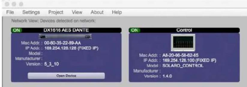
Fig.: 1: Solaro "Network View" - Devices are ON
(f) In the case that the IP Address is not shown correctly (i.e. DHCP, instead of fixed IP), please launch Solaro Console or Control software again and be sure to select the correct network interface settings in the first menu while the application is starting!
IP reset with software
Each connected device also has a reset function by software. In Network View of Solaro Console software, right click the device and select device setup > network: "Change network configuration" like shown below.
Note: If DX1616 is not responding correctly after changing IP Address, please proceed a power cycle of DX1616 and wait for re-booting.
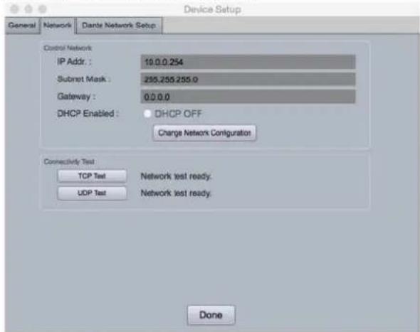
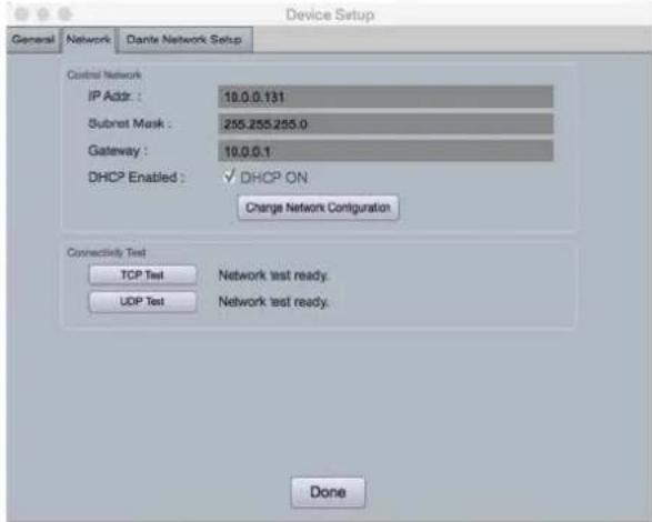
Fig.: 2:Device Setup - Network IP Addresses and DHCP
Multiple Processor Devices Connected to the Network – No DHCP Available
Where you will be connecting multiple DX1616 processors in your network and DHCP is not available, the user will have to manually assign unique static IP addresses to each processor or device. See - manual assignment of IP addresses.
DX1616 connected and powered up
With your processor device/s connected as a network or directly to your computer, power on all devices.
(a) On power up the processors Power Status LED will light.
(b) If the processor has an Ethernet cable / network cable connected the Network Status LED on the front of the processor will light - once the processor initializes. If there is no Ethernet / network cable attached it will remain off.
Note: This does not mean that you have established a network connection – only that an Ethernet or network cable is connected to the processor. Proper Network Connection and Operation is indicated/displayed only in the software's Network View page – see Network View & Connection.
(c) Upon being powered up the processor will search for a DHCP router or server to obtain an IP address. If it locates DHCP it will connect quickly. If you are using a direct or indirect Non-DHCP connection you will have followed the instructions to connect to a single processor or multiple processors – where DHCP is not available.
(d) When the processor and software are connected and commands are being sent to the device the Network Status LED will flash.
Launch the Solaro Console Software

Upon opening the Solaro Console software you will be shown the "Solaro Console Startup" window. It provides 4 possible selections: "New Design Project", "Open Design Project", Start "Network View" (Network View will also be available to you as a separate button located at the top right of the Project View/Design Mode work area page. The fourth selection is Start "Dante View" to manage real time Dante connections.
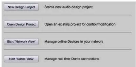
Fig.: 3: Solaro Console start up window
Network View
(a) Click Start "Network View" from the Solaro Console Startup window shown above. The Network View displays all DX1616 and control devices connected to the network plus information such as the processor device model, a green, yellow or red network connection indicator, the IP address, and the devices Firmware version.
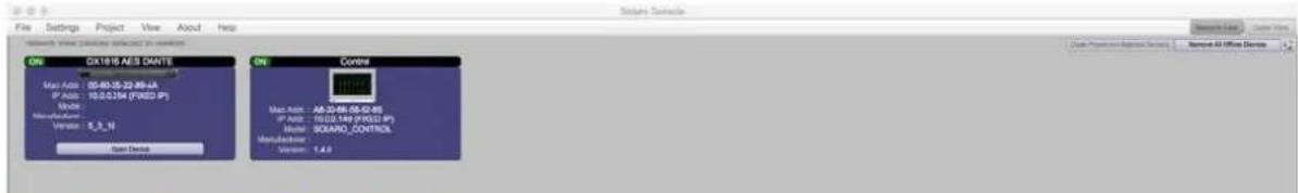
Fig.: 4: Solaro Console "Network View"
(b) In Network View you should now see your DX1616 connected to the network router block and the Network Connection Indicator to the left of the processor device model should be Green/On (meaning it is connected and operational).
(c) Firmware version: Any device firmware / software incompatibility will be indicated in Network View with either a Red warning symbol (connected but firmware is not compatible - must upgrade device firmware) or a Yellow symbol (connected and may function but firmware is not a recommended version). See Firmware Upgrade.
(d) If your processor and software have tot connected properly you will see a Red or Yellow connection indicator to the left of the processor or device model in Network View indicating a connection or operational problem.
Network Connection Indicators
• Green (On) - Connected and operational.
• Yellow – Connected but Not Operational.
• Red (Off) - The processor is offline
- Not connected – no communication between the Solaro Console software and the DX1616 processor. Check cables and connections.
Note: This could be a temporary offline interruption if the processor is busy performing a firmware upgrade, re-booting, searching for DHCP or defaulting to its default IP address.
TCP/IP Connection Trouble Shooting
While in "Network View" if there is a Yellow network connection indicator next to the processor device model the device is connected/online - but Not Ready / Not Operational.
The three most common reasons for this Yellow connection indicator is the result of
(a) A non-DHCP connection where multiple processors are in use and each device needs a unique IP address manually assigned to it
(b) Where a non-DHCP direct or indirectly connected - single processor device is not reverting to its default IP address and/or is holding onto its previous address and
(c) Software/Firmware incompatibility.
(d) Your computer is featuring more than one network interface
Solutions
(a) See instructions- manual assignment of IP addresses
(b) Reset the processor to its default IP address
(c) Check device firmware version in Network View & perform a processor firmware upgrade.
(d) If you computer is featuring more than one network interfaces, i.e. LAN port and WiFi: Make sure, that both interfaces do NOT have the same IP range! If you do not want to change the IP addresses, just deactivate the not needed network interface and re-launch Solaro Console software.
Those connection solutions resolve 99% of any Yellow indicator connection issues but to assist further, when the indicator is Yellow you can hover your cursor over the device and there is a pop-up Tooltip message to tell you the kind of issues it has detected.
A few message and solution examples below.
Message: Device not ready.
Solution: Wait a minute or two till the device is ready and it should then connect and the indicator turn Green if successful. If the indicator remains Yellow, close the Solaro Console software and then re-open or reset the processor.
Message: Device Schematic Not ready.
Solution: The processor has already been loaded with a DSP design. Give the connection process a minute to connect and if it does not connect close the Solaro Console software, open it again, select Start "Network View" and you should now see that the processor is connected and operational - as indicated by the Green network connection indicator to the left of the processor device model. Solution: If not connected - reset the processor - see IP reset push button / Reset Processor Network Settings (DHCP not available) or IP reset with software.
Message: DSP Processing Error.
Solution: This could be a bad DSP Design schematic. You may need to reload the DSP schematic and restart and/or restart device to reset its DSP chip.
Message: Error in Firmware Upgrade.
Solution: It will print out an error code when you hover your cursor over the device in Network View (Do Firmware Upgrade again).
Manual Assignment of IP Addresses To Multiple Devices – No DHCP:
Unique, manually assigned/static IP addresses are required for each processor or device. (Each processor or device indirectly connected to the PC via a network switch or hub)
Note: Make sure your computer is set to "Obtain IP Address Automatically".
Note: We will set your computer's static IP Address after changing the IP Addresses on all the processors and devices first!
To manually assign static IP addresses to multiple processors and devices,
(a) Connect device number one directly to your PC, reset its IP address (IP Reset) and establish a connection between the device and your PC/Solaro Console software.
(b) Next, in Network View - right click the connected processor or device and select "Device Setup". In the Network Properties window as shown at the right - select "Change Network Configuration" in order to disable DHCP and to insert IP addresses manually (it also provides two built in test procedures, device security, and device information).
(c) With the DHCP button disabled, assign the unique IP Address of 192.168.1.X to the first processor device – where X is a unique number between 0 & 255.
(d) When finished – Select "Apply" to save changes and then "Done" to exit.
(e) Complete steps (a) thru (d) above for each subsequent processor or device so that each is assigned its own unique static IP address (example – might be 192.168.1.180 / 181/ 182/ etc.
(f) Note: Your devices will appear Offline until you assign a static IP address for your PC as described below.
(g) Once all processors and devices have their own unique IP address we will do the same for your PC.
A Static IP Address for your Computer - Multiple Devices – No DHCP:
In this section, we will be navigating through Microsoft Windows to determine your home networking information as it applies to manually assigning a unique static IP address to your computer.
(a) The first step is to open the 'Start Menu' and select Control Panel.
(b) Click View Network Status and Tasks under the Network and Internet header as shown at the right.
(c) Click on Change adapter settings on the left most tab.
(d) Left-Click on Local Area Connection and click the Properties button. Select Internet Protocol Version 4 (TCP/IPv4) then click Properties to access the manual IP settings.
(e) Set up your IP address to be 192.168.1.X where the X can be any value from 0 - 255 - but unique from the other devices that you already manually assigned unique IP addresses to.
(f) Use the following settings for your PC's unique static address: IP Address: 192.168.1.X (Example - IP might be 192.168.1.185 based on my Subnet Mask: 255.255.255.0 unique device addresses above) Gateway: 192.168.1.1 DNS Servers: 192.168.1.1
(g) If you set up your devices as per steps above, you will now see them appear online and connected in Network View in the Solaro Console software.
Firmware update to DX 1616 processor
Once you have the processor device and the Solaro Console software connected and operational and before you start work on a DSP design project - make sure your processor has the latest firmware installed (www.rcf.it - verify, download latest firmware, save file to your PC and proceed below with firmware upgrade procedure if required).
Note: You must not disrupt power during the Firmware Upgrade process!
(a) In Network View – Right click the device, Select "Firmware Upgrade" from the menu and follow the instructions.
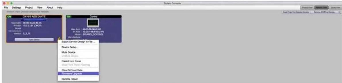
Fig.: 5: DX1616 Firmware update - starting the process
(b) As indicated during the firmware upgrade procedure – a firmware upgrade will erase all saved data on the device. Thus perform this procedure before you load a complete DSP Design Project into the processor device (or re-transfer/save a saved project design file to the processor device after the processor firmware upgrade is complete).
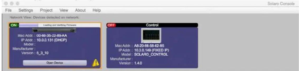
Fig.: 6: Firmware update in process - Loading and verifying firmware
(c) The status of the firmware update is shown in a horizontal bar. If that bar stops for long time (>5min) and does not continue, just start with the firmware update process again!
Note: during the firmware update process the DX1616 switches automatically the internal relay on and off. This is normal!
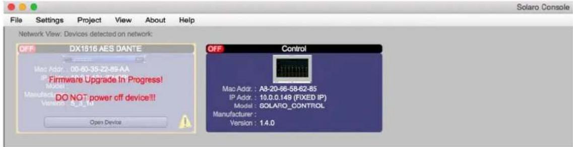
Fig.: 7: Firmware update in process - Do not power off the device
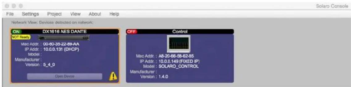
Fig.: 8: Firmware update - device not ready is shown
Note: If the network view shows "Device NOT ready", you have to load your project file into the updated DX1616 and switch to online mode like described in the chapter: Open Project (project file).
(d) Now the update process is finished
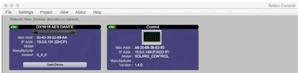
Fig.: 9: Firmware update - process is finished
Note: Depending on the firmware update: If there is still the yellow exclamation mark, please launch Solaro Console again or proceed a power cycle on DX1616.
Setting up Solaro Console & Control Software
In the following procedure the DX1616 is connected and operational!
Open Project (project file)
Open Project as selected under "File" is where you open or access previously worked on and saved DSP design project files.
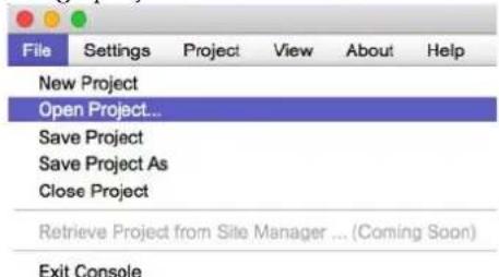
Fig.: 10: Open project file
Save Project File on the computer
(a) Select "Save Project As" under the File menu at the top left of the application to name and save your design project and "Save Project" to save as you work.
Note: This saves the DSP design project you are working on to your PC (not to the physical processor device). See "Switch to Online Mode" below to accomplish that.
(b) Note: We recommend that you save the project file twice. Once to create or keep the RCF factory Master File (*.pjxml) and a second time to create a user work file. Continue working with the Work File and keep the Master File as reference or fall back.
Launch DX1616 Control Software

The DX 1616 processor shall be remotely controlled using Solaro Console software GUI and with your PC/Mac or Android, iOS device.
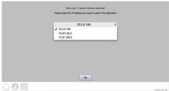
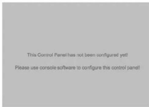
Fig.: 11: Solaro Control - selecting network interface
Fig.: 12: "This Control Panel has not been configured yet"
If several network adapters are found, select the IP Address, which fits to your network (project).
Note: If you computer is featuring more than one network interfaces, i.e. LAN port and WiFi: Make sure, that both interfaces do NOT have the same IP range! This will cause trouble in the Control app's communication. If you do not want to change the IP addresses, just deactivate the not needed network interface.
When launching for the very first time, the message "This Control Panel has not been configured yet" is shown. This is correct and not a mal function. Please proceed the mapping process like described below in the chapter "map physical devices".
Note: To map the "Control" panel (your remote computer or iPad) keep Solaro Control running on your computer/ iPad! Your Computer must be connected to the same network like DX1616. If so, in Solaro Console software your remote computers' Mac Address will be available to map physical devices.
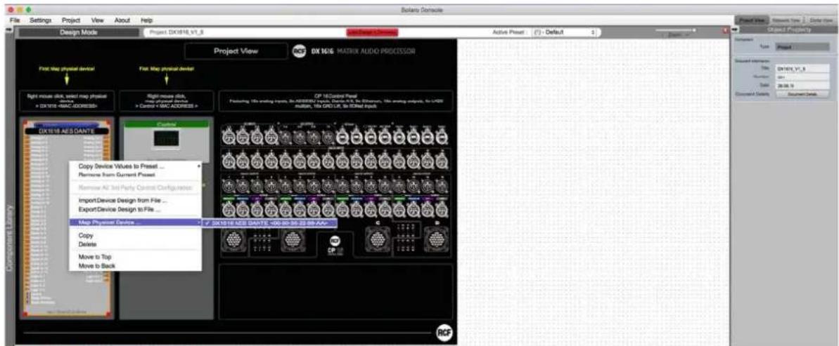
Map Physical Devices – DX1616 and Control Panel
Next, with the DX 1616 processor module for this application placed in the Project View/Design Mode work area (and when the processor device is connected to the Solaro Console software) you need to map the DX 1616's software processor module in the work area with the actual physical DX 1616 processor device that is connected to the PC.
Note: The mapping process is only need if:
• A DX1616 and its control devices (PC, iPad) are used for the very first time in a network
• The hardware was changed (a new DX1616, a new PC, A new iPad)
Warning&detected,&device&“xxxx”&NOT&mapped&
 Fig.: 14: Warning detected - Device not mapped This message will pop up, if your control device panel is not mapped, or you have a second panel (i.e. for ipad) which is not mapped. If you are not going to use the second control panel (ipad), you have to delete this control panel in your project file. Switch&to&Online&Mode:&(Transfer/Save&DSP&design&project&to&DX1616)&& After successful mapping of the devices you are ready to switch to online mode: (a) Click the red "Load Design To Device" button at the top of the Project View / Design Mode work area page – as shown below (not visible if a network interface is not detected – you are working Offline)  Fig.: 15: Load Design to Devices (b) You will be asked if you want to load the settings to the DX1616 ("device"). "Yes": when you load for the very first time the project file settings to the DX1616 you have to confirm with "yes". "No": Select "No" if you want to switch to Online Mode and still want to use the current (formally loaded design project) parameter settings in DX1616.  Fig.: 16: Online mode startup window After confirming with "No" a second message box might open and your confirmation with "Ok" is needed to proceed with the process. Note: Please be not confused. You will get connected with all the last parameter settings done in DX1616 before. Important is, that you selected "No" in the first message box "No = This option will start online mode without loading in the parameters. Will use the existing parameters from device".  Fig.: 17: Update device with project settings Note: Any problems – check auto warning messages in Network View regarding any Firmware Incompatibility with Software (will not load your design into device if any incompatibility). (c) the procedure "Load Design to Devices" may take 1 minute in total depending on the number of presets included in the project file. On top of the screen you will see a status bar given the percentage progress. Note: At 90% the bar will stop and you might hear a mechanical clicking noise in DX1616. This is the relay, which will mute all in- and outputs during the write process. The last 10% can take time to prepare the DX1616 and its presets. After 100% the relay will unmute the system.  Fig.: 18: Preparing devices to online control message Note that the Design Mode label at the top of the page has changed to red "Online Control" and that the "Load Design to Device" button (now grey) has been re-named in "Go Back to Design Mode".  Fig.: 19: "Go back to Design Mode" - switching to OfflineSwitch back to Design Mode (Offline Mode)
Note: You can make parameter adjustments to the DX1616 while in Online Mode. When you do, upon switching back to Design Mode you will be asked:  Fig.: 20: Copying settings to project file - yes ore not “do you want to copy the Online Device parameter settings back to your project (file)” - “yes” or “no”. So you can make all kinds of parameter adjustment changes to the DSP modules in Online Mode, hear their effect live, and not affect the related DX1616 project file as saved on your PC if you select "No" from that menu. Or select "Yes" to modify your (personal) project file and continue working or "Yes" and "Save As" immediately to save the changed processor settings to new project file. Note: Remember to keep the origin RCF default project file \*.pjxml as backup!Operating DX1616
After successful network connection of DX1616 including the host computer and a control device (host computer, second computer or iPad), this chapter explains the operating of DX1616 in all aspects. Note: for save and comfortable operating, we recommend to use at lease one host PC running the Solaro Console software & Solaro Control Software. For some reasons also the addition of a remote computer (or iPad) with Solaro Control running is useful.Recommended operating with Solaro Console and Control
 The best performance and maximum control is reached by using both Solaro Console and Control software. Even no remote computer is a must have, because you can run also the Solaro Control App on your host PC. The Solaro Control GUI offers a 4:3 ratio fixed size remote panel (1024x720 px) which can be used on a PC, Macbook or iPad in the same way.Solaro Control settings
 Fig.: 21: Solaro Control settings In the settings menu you can adjust: • the language • network condition to manage the bandwidth • set timing to sync DSP device data (5 sec recommended) - set timing to sync 3 ^rd party devices (will be disabled by default) In the settings, you can also read out the device name (by default "Control"), the IP Address and Mac Address of the mapped device.Home screen (Router 1-8)
Philosophy: The main screen is called "Home" and gives the most important information about all the incoming signals (on top of the screen), its routing(s) to DSP output modules (on the right of the screen), mutes, levels, limits and delays. The output DSP modules have easy to understand common labels (cannot be edited by the user) like "Main L", "Side L", "Fill Front", "Fill Center", "Sub 1" and so on. Output Delay: For each DSP output you can set a delay by double clicking the parameter. The maximum is 500ms. You can type in the delay in the "home" screen or in the DSP module screen. Note: If you need more delay, use the "Delay L/R" or "AUX" DSP modules in "Router 9-16" section Router: The router in the center of the screen allows to assign each input channel to one or several DSP modules individually. For each connection you can adjust the level from 0dB to negative values by double clicking the parameter. Note: You can assign at the same time several inputs to a DSP module (Desk A, B, C, D and so on) please be aware the more inputs are routed (X) and connected, the more noise occurs on the output! We recommend using the "Group Mute" button to mute the not (yet) needed inputs or de-select them in the matrix! Mutes: The mute bottoms on the left will mute the complete signal paths (all signals from input section) to its DSP module on the right. Fig.: 22: Home Screen (Router 1-8)Home screen (Router 9-16)
Use that button to get access to the output DSPs 9 to 16 Note: The "Delay" and "AUX" outputs can have 1000ms of delay! To go back use the “<Input EQs
Each of the input groups offers fixed stereo paired or mono EQs: - Low Shelf (Gain +/-15dB, Frequency 20Hz-20kHz, Bandwidth 1.6 - 3.0 Oct) - 4x parametric EQ (Gain +/-15dB, Frequency 20Hz-20kHz, Bandwidth 0.01 - 4.0 Oct) High Shelf (Gain +/-15dB, Frequency 20Hz-20kHz, Bandwidth 1.6 - 3.0 Oct) Note: due to the architectural DSP design you will have separated EQ windows for each type!  Fig.: 27: Source EQ - LS, PEQ, HSInput source compensation
Beside the input delay for the signal processing section, a separated "source compensation" is available in each pair of the input channels  Fig.: 28: Info menu about "source compensation"Why this?
Imagine you desk(s) can send AES/EBU or analog signal at the same time, the inputs of DX 1616 must be switched between analog or AES/EBU. Note: while switching an input channel pair to AES/EBU, you will have 0.35ms more latency compared to the analog inputs. The reason is, that DX1616 uses a high quality sample rate converter switching all incoming sample rates to its internal 48kHz. When you click the "info" button next to the section source compensation you will see the help file explaining thisInput section Desk C, Aux D, Aux E
These input groups offer pre-configured stereo routings and will be used for desks with L+R sum or other stereo sources. The performance is the same compared to "Desk A and B"  Fig.: 29: Input section "Desk C, Aux D, Aux E"Input section Mic 1&2
The input group "Mic 1&2" (source 15, 16) offers beside line inputs also additionally switchable Line/Mic inputs. The source processing is managed by two separate mono channels 15, 16. flowchart
graph TD
    A["Analog Inputs"] --> B["Input: 15"]
    C["Dente Inputs"] --> D["Input: 16"]
    B --> E["Line/Mic: Mic"]
    D --> F["Line/Mic: Mic"]
    E --> G["Info Source Compensation"]
    F --> H["Info Source Compensation"]
    G --> I["Source Delay: No Delay 0.00ms"]
    H --> J["Source Delay: No Delay 0.00ms"]
    I --> K["Polarity Invert Invert Invert Invert Invert"]
    J --> L["Analog Gain: 0.0dB 0.0dB"]
    K --> M["Meter -80.0dBu -80.0dBu -80.0dBu -80.0dBu"]
    L --> N["Mole 0.0dB 0.0dB 0.0dB 0.0dB"]
    M --> O["Mute Mute Mute Mute"]
    N --> P["Compressor"]
    P --> Q["Champ Bypass Ratio"]
    Q --> R["Bypass Ratio 2:1"]
    R --> S["THO 10.0ms Release 20.0dBu 10ms"]
    S --> T["Bypass Ratio 2:1"]
    T --> U["THO 10.0ms Release 20.0dBu 10ms"]
    U --> V["Compressor Ratio 2:1"]
    V --> W["THO 10.0ms Release 20.0dBu 10ms"]
    W --> X["Compressor Ratio 2:1"]
    X --> Y["THO 10.0ms Release 20.0dBu 10ms"]
    Y --> Z["Compressor Ratio 2:1"]
    Z --> AA["THO 10.0ms Release 20.0dBu 10ms"]
    AA --> AB["Compressor Ratio 2:1"]
    AB --> AC["THO 10.0ms Release 20.0dBu 10ms"]
    AC --> AD["Compressor Ratio 2:1"]
    AD --> AE["THO 10.0ms Release 20.0dBu 10ms"]
    AE --> AF["Compressor Ratio 2:1"]
    AF --> AG["THO 10.0ms Release 20.0dBu 10ms"]
    AG --> AH["Compressor Ratio 2:1"]
    AH --> AI["THO 10.0ms Release 20.0dBu 10ms"]
    AI --> AJ["Compressor Ratio 2:1"]
    AJ --> AK["THO 10.0ms Release 20.0dBu 10ms"]
    AK --> AL["Compressor Ratio 2:1"]
    AL --> AM["THO 10.0ms Release 20.0dBu 10ms"]
    AM --> AN["Compressor Ratio 2:1"]
    AN --> AO["THO 10.0ms Release 20.0dBu 10ms"]
    AO --> AP["Compressor Ratio 2:1"]
    AP --> AQ["THO 10.0ms Release 20.0dBu 10ms"]
    AQ --> AR["Compressor Ratio 2:1"]
    AR --> AS["THO 10.0ms Release 20.0dBu 10ms"]
    AS --> AT["Compressor Ratio 2:1"]
    AT --> AU["THO 10.0ms Release 20.0dBu 10ms"]
    AU --> AV["Compressor Ratio 2:1"]
    AV --> AW["THO 10.0ms Release 20.0dBu 10ms"]
    AW --> AX["Compressor Ratio 2:1"]
    AX --> AY["THO 10.0ms Release 20.0dBu 10ms"]
DSP modules output section
In total you have 16 output DSP modules, offering: - 4 Band parametric EQ - All-Pass Filter 1 ^st and 2 ^nd order (not in modules "Subs", "Delay" and "Aux") - High Pass Filter: 6dB, 12dB, 18dB, 24dB slope - Low Pass Filter: 6dB, 12dB, 18dB, 24dB slope - Output level - Polarity switch - Output delay of 500ms (1000ms in modules "Delay" and "Aux") - Output compressor: adjustable ratio, THD, attack, release, bypass Note: The default THD is +20dB and bypass on (=compressor off) to get the full, not compressed level out of the DX1616. This compressor is used to set an acoustical level (i.e. of a front fill speaker). It is not needed (or even recommended) to set a protection limiter. This is done in the active RCF speaker itself.  Fig.: 31: Example of DSP module "Main L" Tipp: To navigate very quickly through the DSP output modules "Main L"> "Main R" and so on, you can use the "<< back" and ">>forward" buttons on top of the screen  Fig.: 32: Quick navigation << and >> through the DSP modules  Fig.: 33: DSP module with All-Pass Filter Note: An All-Pass filter shifts phase, not magnitude! Use that filter only in combination with a FFT analyzer to optimize the phase transfer of a speaker system! By default, the All-Pass filters in DX1616 are switched off (bypass is on)Analog/ AES Output patch
 Fig.: 34: Analog/ AES output patch DX1616 offers a powerful and fully flexible output patch to assign specific analog outputs (XLR socket and LK25 multipin) to a DSP module. Example: The physical output of the module "Main L" can be assigned to output 1+2+3+4 or any other to use i.e. several outputs as line drivers. This will be done within an array to drive just 4 or 6 cabinets in daisy chain. Technical background: By connecting input boards in daisy chain, the overall impedance will degrease and this can result in hearable high frequency losses (also depending on the quality of the output drivers o your source). flowchart
graph TD
    subgraph Left
        A["1"] --> B["2"]
        B --> C["3"]
        C --> D["4"]
        D --> E["5"]
        E --> F["6"]
        F --> G["7"]
        G --> H["8"]
        H --> I["9"]
        I --> J["10"]
        J --> K["11"]
        K --> L["12"]
        L --> M["13"]
        M --> N["14"]
        N --> O["15"]
        O --> P["16"]
        P --> Q["Main L"]
        P --> R["Fill L"]
        P --> S["Delay L"]
        P --> T["AUX L"]
        P --> U["Main R"]
        P --> V["Fill R"]
        P --> W["Delay R"]
        P --> X["AUX R"]
        P --> Y["Sub 1"]
        P --> Z["SUB 1"]
        P --> AA["Sub 2"]
        P --> AB["SUB 3"]
        P --> AC["Sub 4"]
        P --> AD["Center"]
    end

    subgraph Right
        A2["A"] --> B2["B"] --> C2["C"] --> D2["D"]
    end

    subgraph Analog Outputs
        A1["A"] --> A2["A"] --> A3["A"] --> A4["A"] --> A5["A"] --> A6["A"] --> A7["A"] --> A8["A"] --> A9["A"] --> A10["A"] --> A11["A"] --> A12["A"] --> A13["A"] --> A14["A"] --> A15["A"] --> A16["A"] --> A17["A"] --> A18["A"] --> A19["A"] --> A20["A"] --> A21["A"] --> A22["A"] --> A23["A"] --> A24["A"] --> A25["A"] --> A26["A"] --> A27["A"] --> A28["A"] --> A29["A"] --> A30["A"] --> A31["A"] --> A32["A"] --> A33["A"] --> A34["A"] --> A35["A"] --> A36["A"] --> A37["A"] --> A38["A"] --> A39["A"] --> A40["A"] --> A41["A"] --> A42["A"] --> A43["A"] --> A44["A"] --> A45["A"] --> A46["A"] --> A47["A"] --> A48["A"] --> A49["A"] --> A50["A"] --> A51["A"] --> A52["A"] --> A53["A"] --> A54["A"] --> A55["A"] --> A56["A"] --> A57["A"] --> A58["A"] --> A59["A"] --> A60["A"] --> A61["A"] --> A62["A"] --> A63["A"] --> A64["A"] --> A65["A"] --> A66["A"] --> A67["A"] --> A68["A"] --> A69["A"] --> A70["A"] --> A71["A"] --> A72["A"] --> A73["A"] --> A74["A"] --> A75["A"] --> A76["A"] --> A77["A"] --> A78["A"] --> A79["A"] --> A80["A"] --> A81["A"] --> A82["A"] --> A83["A"] --> A84["A"] --> A85["A"] --> A86["A"] --> A87["A"] --> A88["A"] --> A89["A"] --> A90["A"] --> A91["A"] --> A92["A"] --> A93["A"] --> A94["A"] --> A95["A"] --> A96["A"] --> A97["A"] --> A98["A"] --> A99["A"] --> A100["A"]
    end

    subgraph Control
        CP16["CP 16 CONTROL PANEL"]
    end

    note["Note: The default output patch uses 8 DSP modules and 8 outputs. Each of the outputs will be supported by one RDNet channel"]
    note["Help-Output-Patch"]
    note
    Legend
    direction TB
    classDef input fill:#f9f,stroke:#333,stroke-width:2px;
    classDef output fill:#ccf,stroke:#333,stroke-width:2px;
    classDef control fill:#cfc,stroke:#333,stroke-width:2px;
    class CP16
    note right of CP16
    note right of CP16
    note left of CP16
    note right of CP16
    note bottom of CP16
    note top of CP16
    note bottom of CP16
    note top of CP16
    note bottom of CP16
    note bottom of CP16
    note top of CP16
    note bottom of CP16
    note top of CP16
    note bottom of CP16
    note top of CP16
    note bottom of CP16
    note top of CP16
    note bottom of CP16
    note top of CP16
    note bottom of CP16
    note top of CP16
    note bottom of CP16
    note top of CP1E
    note bottom of CP1E
    note top of CP1E
    note bottom of CP1E
    note top of CP1E
    note bottom of CP1E
    note top of CP1E
    note bottom of CP1E
    note top of CP1E
    note bottom of CP1E
    note top of CP1E
    note bottom of CP1E
    note top of CP1E
    note bottom of CP1E
    note bottom of CP1E
    note top of CP1E
    note bottom of CP1E
    note top of CP1E
    note bottom of CP1E
    note top of CP1E
    note bottom of CP1E
    note top of CP1E
    note bottom of CP1E
    note top of CP1E
    note bottom of CP1E
    note top of CP1C
    note bottom of CP1C
    note top of CP1C
    note bottom of CP1C
    note top of CP1C
    note bottom of CP1C
    note top of CP1C
    note bottom of CP1C
    note top of CP1C
    note bottom of CP1C
    note top of CP1C
    note bottom of CP1C
    note top of CP1C
    note bottom of CP1C
    note bottom of CP1C
    note top of CP1C
    note bottom of CP1C
    note top of CP1C
    note bottom of CP1C
    note top of CP1C
    note bottom of CP1C
    note top of CP1C
    note bottom of CP1C
    note top of CP1C
    note bottom of CP1C
    note top of CP1E
    note bottom of CP1E
    note top of CP1E
    note bottom of CP1E
    note top of CP1E
    note bottom of CP1E
    note top of CP1E
    note bottom of CP1E
    note top of CP1E
    note bottom of CP1E
    note top of CP1E
    note bottom of CP1E
Dante Output Patch
Note:%The%Dante%outputs%will%NOT%follow%in%the%way%you%assign%the%analog/%AES%patch!%Each%Dante%channel%is%fixed%permanently%to%a%DSP%output%module.% The%table%below%shows%the%fixed%routing:%| DSP | Main L | Main R | Fill L | Fill R | Side L | Side R | Fill Front | Sub 1 |
| Dante Out | 1 | 2 | 3 | 4 | 5 | 6 | 7 | 8 |
| % | ||||||||
| DSP | Sub 2 | Sub 3 | Sub 4 | Fill Center | Delay L | Delay R | Aux L | Aux R |
| Dante Out | 9 | 10 | 11 | 12 | 13 | 14 | 15 | 16 |
Presets & Resets
 Fig.: 37: Presets DX%1616%is%equipped%with%a%preset%library.% J System%resets:%% Default:%resets%all%settings%of%DX1616%back%to%RCF%default%values% - Input%Processin g:%rese ts%all%setting s%in%all%inp ut%ch an ne ls%bac k%to%R CF %defau lt%va lues - Reset%output%patch:%resets%all%output%patches%back%to%RCF%default%values% J Module%resets:% Reset%DSP%output%modules%"Mains",%"Fills",%"Side%PA",%"Fill%Front",%"Subs%1+2,%3+4",%"Fill Center"%back%to%default%values%(0dB,%EQ%flat,%delay%0ms,%no%compressor%...)% J All%Module%Reset% Reset%all%modules:%resets%all%settings%in%all%output%DSP%modules%back%to%default%values%(0dB,%EQ%flat,%delay%0ms,%no%com pres sor%...).% Note:%Presets%are%part%of%the%project%file%(\*.pjxml).%Check%RCF%website%for%updates%of%DX1616%project%fi Note:%How%to%cre at e %U s er%Presets,%please%refer%to%the%chapter%"How%can%I%create%a%(user)%preset?"%It%be%done%in%Solaro%Console%software!% %SolaroConsole – without Solaro Control App in combination with a project (\*.pjxml) file
Start%the%Console%software%and%load%the%DX1616%project%file%(\*pjxml).% Note: If this done for the first time, it is needed to map the devices. Please refer to chapter "Map physical devices" above. Note: Once the devices are mapped, the IP- and Mac Addresses are stored in the project file. Next you should select "Load Design to Devices" to switch to online mode.  Fig.: 38: "Online Control" with opened "Control" window Within the project file, you will see the DX1616 processor and the software Control icon "Control". Double click the "Control" icon and you will see the Control Panel and its different screens shown in the menu on the left. Note: This is the same screen you know from your Control Software App, but to select different screens (to navigate through the architecture) you have to use the left menu.  Fig.: 39: "Online Control" control panels and left menu Note: this way to operate the DX1616 is suitable only if Solaro Control App is not running!Solaro Console – without Solaro Control and without project file
 This chapter explains the „emergenvy operating of DX1616“ without the use of Solaro Control App and if no proejct file is loaded. Even if no „Control“ panel is mapped, or the computer with Solaro Control is not available, you can have (limited) access to the DX1616. Note: this way to operate the DX1616 is very different because no GUI is available. You are directly changing parameters in the architecture level!  Fig.: 40: Solaro Console "Network View" As soon the devices are powered up and you start the Solaro Console software, you will find the DX1616 in the section „Network View“. Click the „Open Device“ button and a new window opens showing you the DSP architecture of DX1616 with access to its single modules and functions. flowchart
graph TD
    subgraph Left_Network
        A["Data Bus"] --> B["Module 1"]
        C["Data Bus"] --> D["Module 2"]
        E["Data Bus"] --> F["Module 3"]
        G["Data Bus"] --> H["Module 4"]
        I["Data Bus"] --> J["Module 5"]
        K["Data Bus"] --> L["Module 6"]
        M["Data Bus"] --> N["Module 7"]
        O["Data Bus"] --> P["Module 8"]
        Q["Data Bus"] --> R["Module 9"]
        S["Data Bus"] --> T["Module 10"]
    end

    subgraph Right_Network
        U["Module 1"] --> V["Module 2"]
        W["Module 3"] --> X["Module 4"]
        Y["Module 5"] --> Z["Module 6"]
        AA["Module 7"] --> AB["Module 8"]
        AC["Module 9"] --> AD["Module 10"]
    end

    Left_Network --> Right_Network
    style Left_Network fill:#f9f,stroke:#333
    style Right_Network fill:#bbf,stroke:#333
flowchart
graph TD
    A["Source 1-2 at"] --> B["Multi-94-01-2"]
    B --> C["Delay IN 1-2"]
    C --> D["LS IN 1-2"]
    D --> E["HS IN 1-2"]
    E --> F["PEQ IN 1-2"]
    F --> G["Comp IN 1-2"]
    G --> H["Delay IN 1-2"]
    H --> I["0.0ms Bypass"]
    I --> J["Multi-94-08-8"]
    J --> K["Delay IN 5-8"]
    K --> L["LS IN 5-8"]
    L --> M["Comp IN 1-2"]
    M --> N["Delay IN 5-8"]
    N --> O["Multi-94-07"]
    O --> P["Delay IN 7"]
    P --> Q["LS IN 7"]
    Q --> R["Multi-94-05"]
    R --> S["Delay IN 8"]
    S --> T["LS IN 8"]
    T --> U["HS IN 8"]
    U --> V["PEQ IN 8"]
    V --> W["Comp IN 8"]
    W --> X["Multi-94-06-10"]
    X --> Y["Delay IN 9-10"]
    Y --> Z["LS IN 9-10"]
    Z --> AA["HS IN 9-10"]
    AA --> AB["PEQ IN 9-10"]
    AB --> AC["Comp IN 9-10"]
    AC --> AD["Multi-94-11-12"]
    AD --> AE["Delay IN 11-12"]
    AE --> AF["LS IN 11-12"]
    AF --> AG["HS IN 11-12"]
    AG --> AH["PEQ IN 11-12"]
    AH --> AI["Comp IN 11-12"]
    AI --> AJ["Multi-94-13-14"]
    AJ --> AK["Delay IN 13-14"]
    AK --> AL["LS IN 13-14"]
    AL --> AM["HS IN 13-14"]
    AM --> AN["PEQ IN 13-14"]
    AN --> AO["Comp IN 13-14"]
FAQs
Which are the "sync" options when connecting to DX1616?
Sync from PC to DX1616
To sync from PC to DX1616 means that you want to transfer settings from your project file (offline) to DX1616: (a) Click the red "Load Design To Device" button at the top of the Project View / Design Mode work area page – as shown below (not visible if a network interface is not detected – you are working Offline)  Fig.: 43: "Load Design to Devices" button (b) You will be asked if you want to load the settings to the DX1616 ("device"). "Yes": when want you load this project file settings to the DX1616 you have to confirm with "yes".Sync from DX1616 to PC
You want to connect to DX1616 (switch online), but you want to use the current settings which are in DX1616: (a) Click the red "Load Design To Device" button at the top of the Project View / Design Mode work area page – as shown below (not visible if a network interface is not detected – you are working Offline)  (b) You will be asked if you want to load the settings to the DX1616 ("device"). "No": Select "No" if you want to switch to Online Mode and still want to use the current parameter settings in DX1616.  Fig.: 44: Syncing from PC to DX1616 After confirming with "No" a second message box might open and your confirmation with "Ok" is needed to proceed with the process. Note: Please be not confused. You will get connected with all the last parameter settings done in DX1616 before. Important is, that you selected "No" in the first message box "No = This option will start online mode without loading in the parameters. Will use the existing parameters from device".  Fig.: 45: Update devices with project settingsWhat happens with my last settings in DX1616 when power is switched off?
The DX1616 remembers the last settings. Means if you switch off and on, the DX1616 will restart with all the last settings done before switching off.Stand by of remote computer or network interruption
If your remote computer is shutting down to sleep mode/ stand by, the network connection of Solaro Control App and DX1616 is lost. You will see on your host computer a RED network indicator in the network view.  Fig.: 46: Control is shown "OFF" after stand by or in stand by of Control App When the remote computer is awakening from stand by, the screen of Solaro Control is shown greyed (see picture below). heatmap
Solar Control Home Router 1-8 RCF DX1GIG Presets Out Patch >> Comp Source Level Pro Form Multi Group Multi Group Mute Group Mute Group Mute Group Mute Router 9-16 >> Master 1 2 3 4 5 6 7 8 9 10 11 12 13 14 15 16 Modul Output S.c.b. M.tu: X: 0.0dB O: 0.0dB M.tu: O: 0.0dB F.B L: O: 0.0dB M.tu: X: 0.0dB O: 0.0dB M.tu: O: 0.0dB F.B R: O: 0.0dB M.tu: X: 0.0dB O: 0.0dB M.tu: O: 0.0dB F.B Front: O: 0.0dB M.tu: X: 0.0dB O: 0.0dB M.tu: O: 0.0dB F.B Front: O: 0.0dB Sub 1: O: 0.0dB Router 1-8 • Page No. 1993 x F# Router 9-16 >>Can I operate the DX1616 with Solaro Control App only?
Yes! As soon a project file is loaded to DX1616 and all devices (DX1616, Control Panel) are mapped before, you can just launch Solaro Control App and operate DX1616. Note: This works because the Mac Address and IP Address is part of the project file. Make sure, that you are still working in the same network. Note: While operating DX1616 with Solaro Control App only, please be aware that you are not able to save your settings to a project file! You can do it later on with Solaro Console, because your last settings will be kept in DX1616 even if power is switched off. To safe settings in DX1616 to a project file, please have a look in the chapter "Which are the "sync" options when connecting to DX1616?" and "Sync from DX1616 to PC"How can I safe my settings?
If you would like to safe the settings of your current DX1616 project, please proceed like this: 1. Switch back to Design Mode (Offline Mode). You will be asked, if your current settings shall be copied from DX1616 to the project file. 2. Confirm with "Yes" and safe your project file "File>Safe as" on your computer. 3. You can create a preset of your parameters. Please refer to the chapter "How can I create a (user) preset?" below. Note: Again, please remember to keep the origin RCF project file as back up!Can I use a second Control Devices (iPad) to manage DX1616?
Yes. You have to edit the formally created copy of the origin RCF project file like this: (a) Launch Solaro Console software and open the project file and stay in Design Mode. (b) Copy by right mouse click the "Control" icon and paste it. (c) The name of the copied icon will be "Control-1". You shall re-name it into "iPad" and edit the object color using the object properties on the right side of Solaro Console software. (d) Resize the new panel "iPad": Double click the panel icon and select "Resize Panel" in the menu with 1024 x 718px  Fig.: 48: Creating a second "Control" device  Fig.: 49 Resize "iPad" Panel in 1024x718 (e) Start your hardware device (iPad, second computer) in the same network and launch Solar Control software on it. (f) Map your recently created "iPad" device. See Map Physical Devices - DX1616 and Control Panel. (g) Save your project file on your computer and proceed with "load Design to Devices". Note: You will not be able to "Load Design to Device" until your second control panel is mapped to a physical device. In other words: If the second device (iPad) is not available, the only way is to delete the panel "iPad".How can I create a (user) preset?
You did some personal settings in DX1616 and you would like to safe it as a preset for future recall. (a) Switch back to Design Mode (Offline Mode) When switching back to Design Mode you will be asked:  Fig.: 50: Switching back to Design Mode - Copying parameters to project file “do you want to copy the Online Device parameter settings back to your project (file)” – “yes” or “no”. Select "Yes" to modify your (personal) project file and "Save As" immediately to save the changed processor settings to new project file. Note: Remember to keep the origin RCF default project file \*.pjxml as backup! (b) Double click the "DX 1616" icon in the project view and maximize the window  Fig.: 51: "Design Mode" - project view (c) Select the DSP circuit(s) you want to save. This can be just one module parameter (level, EQ, Mute and so on) or even all currently set parameters. What ever you select will be saved. flowchart
graph TD
    A["Start"] --> B["Module Layout"]
    B --> C{Prevent}
    C -->|No Active Preset| D["Select Preset"]
    C -->|Yes| E["Continue New Preset"]
    style A fill:#f9f,stroke:#333
    style B fill:#ccf,stroke:#333
    style C fill:#cfc,stroke:#333
    style D fill:#fcc,stroke:#333
    style E fill:#ffc,stroke:#333
How can I edit and save a preset?
You exactly start like shown in the chapter "Create preset". Instead of selecting "Create New Preset", just select the one you would like to overwrite (edit). Note: Doing so, you have to follow exactly the same steps starting from (e) like described in the chapter "How can I create a (user) preset?". Otherwise your new values/settings are NOT available in Solaro Control App!Technical Data
Inputs and Outputs % ?6^7Y%?`^_ "6 ]Q% g&P[%Da`3%Me"8"6]_N% !a"6Y`%!'Z4% ;;9%M'^6%]X47XYNR%<&9%M8"'__%]X4]7XYN% D7Y^7Y%?`^_ "6]Q% f%&
- DX1616 User Manual
- Table of content
- QUICK START GUIDE 5
- FAQS 30
- TECHNICAL DATA 38
- Table of figures
- Quick Start Guide
- What's in the Box
- What you need to provide
- Safety information
- Introduction and Description
- Front Panel
- Power Status LED
- Network Status LED
- Input/Output Signal Indicators
- Rear Panel
- Install the Solaro Console & Control software
- Windows users
- Firewall – allow access!
- Download and save DX1616 project files
- Initial Device Connectivity
- A DHCP enabled Router, Server, or Router/Switch
- A Non-DHCP enabled direct connection or indirectly via an Ethernet switch.
- A Single Processor or Device in the Network Only - No DHCP Available
- IP reset push button / Reset Processor Network Settings (DHCP not available)
- IP reset with software
- Multiple Processor Devices Connected to the Network – No DHCP Available
- DX1616 connected and powered up
- Launch the Solaro Console Software
- Network View
- TCP/IP Connection Trouble Shooting
- The three most common reasons for this Yellow connection indicator is the result of
- Solutions
- A few message and solution examples below.
- Manual Assignment of IP Addresses To Multiple Devices – No DHCP:
- A Static IP Address for your Computer - Multiple Devices – No DHCP:
- Firmware update to DX 1616 processor
- Setting up Solaro Console & Control Software
- Open Project (project file)
- Save Project File on the computer
- Launch DX1616 Control Software
- Map Physical Devices – DX1616 and Control Panel
- Warning&detected,&device&“xxxx”&NOT&mapped&
- Switch back to Design Mode (Offline Mode)
- Operating DX1616
- Recommended operating with Solaro Console and Control
- Solaro Control settings
- Home screen (Router 1-8)
- Home screen (Router 9-16)
- Input section Desk A, B
- Input EQs
- Input source compensation
- Why this?
- Input section Desk C, Aux D, Aux E
- Input section Mic 1&2
- DSP modules output section
- Analog/ AES Output patch
- Dante Output Patch
- Presets & Resets
- SolaroConsole – without Solaro Control App in combination with a project (\*.pjxml) file
- Solaro Console – without Solaro Control and without project file
- FAQs
- Which are the "sync" options when connecting to DX1616?
- Sync from PC to DX1616
- Sync from DX1616 to PC
- What happens with my last settings in DX1616 when power is switched off?
- Stand by of remote computer or network interruption
- Can I operate the DX1616 with Solaro Control App only?
- How can I safe my settings?
- Can I use a second Control Devices (iPad) to manage DX1616?
- How can I create a (user) preset?
- How can I edit and save a preset?
- Technical Data
Marque : RCF
Modèle : Matrix Audio DX1616
Catégorie : Processeur