
AC70 - Autopilote marine SIMRAD - Notice d'utilisation et mode d'emploi gratuit
Retrouvez gratuitement la notice de l'appareil AC70 SIMRAD au format PDF.

| Type de produit | Calculateur d'autopilote marine |
| Marque | Simrad |
| Modèle | AC70 |
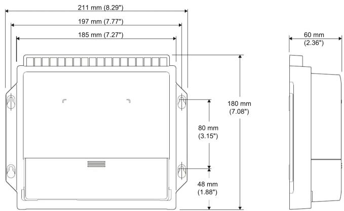
| Dimensions (L x l x H) | 200 x 150 x 50 mm |
| Poids | 1.2 kg |
| Tension d'alimentation | 10-32 V DC |
| Consommation électrique | 0.5 A |
| Protocoles de communication | NMEA 2000, SimNet |
| Fonctions principales | Pilotage automatique, commande de barre, modes vent et route |
| Type de pilote | Calculateur avec capteur de cap intégré |
| Température de fonctionnement | -10°C à +55°C |
| Indice de protection | IPX6 |
| Matériau du boîtier | Aluminium moulé |
| Contenu de l'emballage | Calculateur AC70, faisceau de câbles, guide d'installation rapide |
| Installation | Montage sur cloison, connexion au système de direction et au réseau NMEA |
| Entretien et nettoyage | Nettoyer avec un chiffon doux légèrement humide. Ne pas utiliser de solvants. |
| Sécurité | Installation et réglage par un professionnel qualifié. Couper l'alimentation avant toute intervention. |
| Pièces détachées et réparabilité | Pièces disponibles auprès des revendeurs agréés Simrad. Réparation par centre agréé. |
| Certifications | CE, FCC, NMEA 2000 certifié |
| Garantie | 2 ans |
FOIRE AUX QUESTIONS - AC70 SIMRAD
Questions des utilisateurs sur AC70 SIMRAD
0 question sur cet appareil. Repondez a celles que vous connaissez ou posez la votre.
Poser une nouvelle question sur cet appareil
Téléchargez la notice de votre Autopilote marine au format PDF gratuitement ! Retrouvez votre notice AC70 - SIMRAD et reprennez votre appareil électronique en main. Sur cette page sont publiés tous les documents nécessaires à l'utilisation de votre appareil AC70 de la marque SIMRAD.
MODE D'EMPLOI AC70 SIMRAD

SIMRAD
AC70 COMPUTER
INSTALLATION GUIDE
natural_image
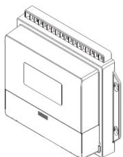
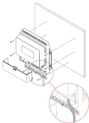
Isometric line drawing of a rectangular electronic device with ventilation slots and a control panel (no text or symbols)Parts included
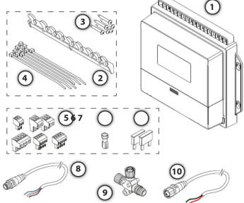
1 1 * AC70 Computer
2 1 * Cable retainer
3 6 * Fixing screws, 3.5 * 19 mm (DIN7981B)
4 10* Strips
5 6* Connectors
6 1* Receptacle
7 2 * 30 Amp Fuse
8 1* Micro-C Drop cable (male)
9 1* Micro-C T-Joiner
1* Micro-C Power cable with 120 Ohm terminator, female
1 1* Micro-C Terminator, 120 Ohm (male)
Dimensions

The image is too blurry to recognize any text content.
For technical specifications,
certificates and declarations,
refer to the product web site on:

pro.simrad-yachting.com

www.simrad-yachting.com
Mounting
natural_image
Technical line drawing of a mechanical assembly with internal components and a magnified inset showing detail (no text or symbols)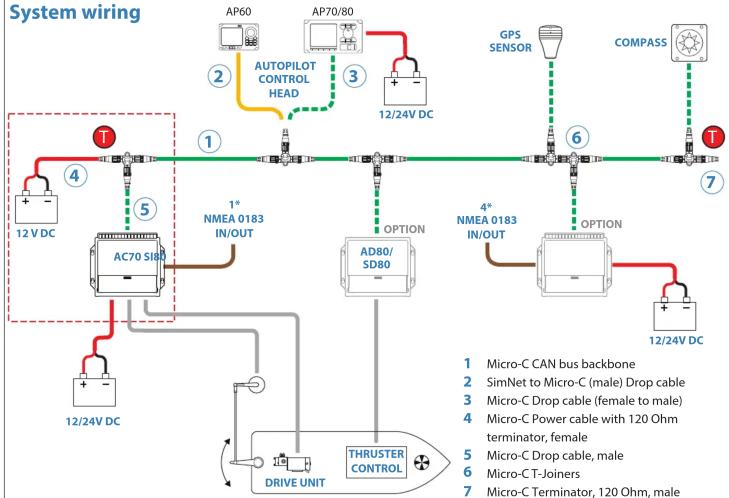
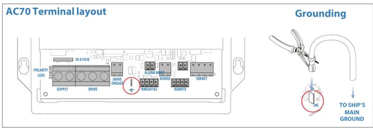
flowchart
graph TD
A["12V DC"] --> B["AC70 S180"]
B --> C["AP60"]
B --> D["AP70/80"]
B --> E["AD80/SD80"]
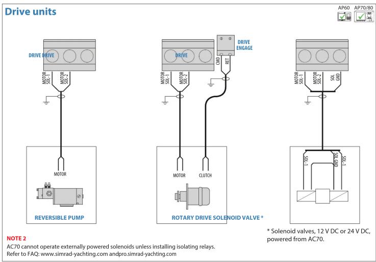
B --> F["DRIVE UNIT"]
B --> G["THRUSTER CONTROL"]
B --> H["OPTION"]
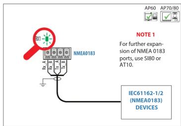
B --> I["NMEA 0183 IN/OUT"]
B --> J["Autopilot Control Head"]
B --> K["GPS SENSOR"]
B --> L["COMPASS"]
B --> M["12/24V DC"]
B --> N["4* NMEA 0183 IN/OUT"]
B --> O["4* NMEA 0183 IN/OUT"]
style A fill:#f9f,stroke:#333
style B fill:#ccf,stroke:#333
style C fill:#cfc,stroke:#333
style D fill:#fcc,stroke:#333
style E fill:#cff,stroke:#333
style F fill:#ffc,stroke:#333
style G fill:#fcc,stroke:#333
style H fill:#ffc,stroke:#333
style I fill:#fcc,stroke:#333
style J fill:#ffc,stroke:#333
style K fill:#fcc,stroke:#333
style L fill:#fcc,stroke:#333
style M fill:#fcc,stroke:#333
style N fill:#fcc,stroke:#333
style O fill:#fcc,stroke:#333
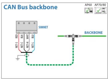
flowchart
graph TD
    A["NEF-5"] --> B["SIMNET"]
    C["NEF-C"] --> B
    D["NEF-H"] --> B
    E["NEF-L"] --> B
    B --> F["BACKBONE"]
    style A fill:#f9f,stroke:#333
    style C fill:#f9f,stroke:#333
    style D fill:#f9f,stroke:#333
    style E fill:#f9f,stroke:#333
    style F fill:#ccf,stroke:#333


Marque : SIMRAD
Modèle : AC70
Catégorie : Autopilote marine