
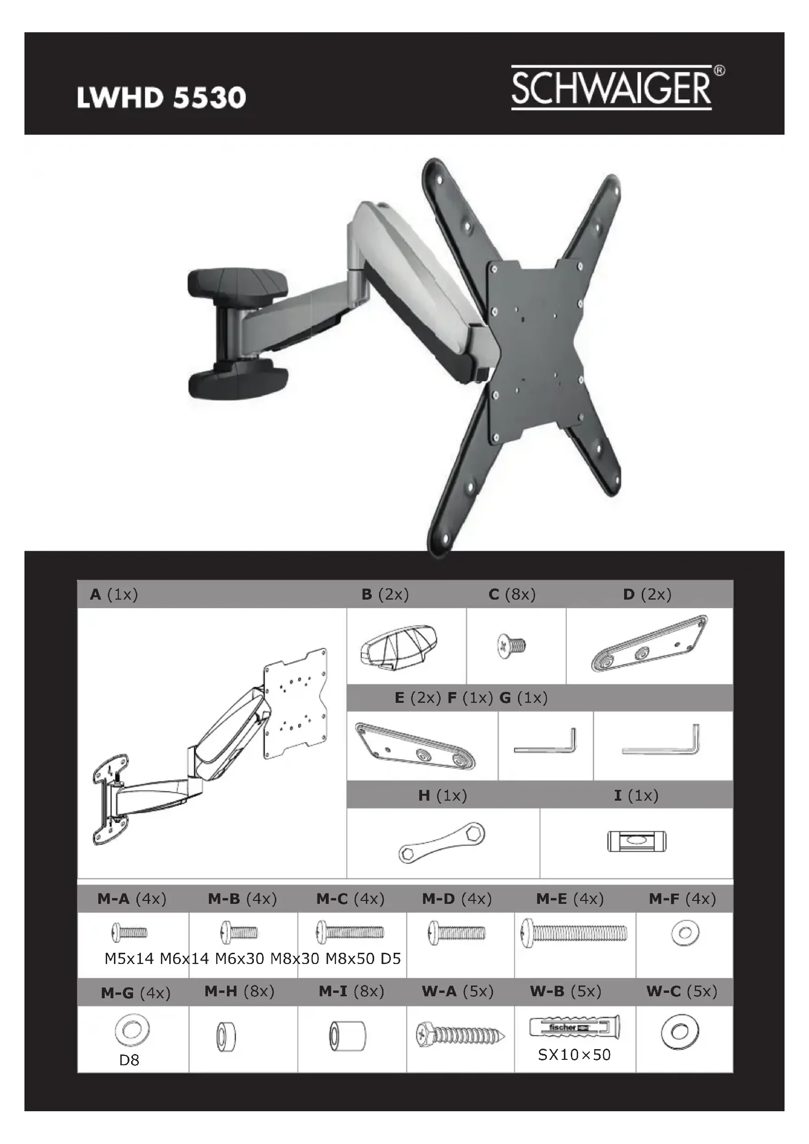
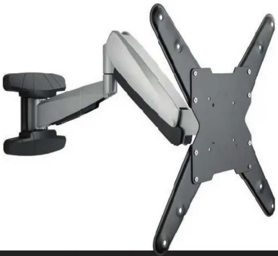
LWHD5530 511 - Support mural Schwaiger - Notice d'utilisation et mode d'emploi gratuit
Retrouvez gratuitement la notice de l'appareil LWHD5530 511 Schwaiger au format PDF.
| Type de produit | Support mural |
| Marque | Schwaiger |
| Modèle | LWHD5530 511 |
| Matériau | Acier |
| Dimensions maximales (L × H) | 400 × 300 mm |
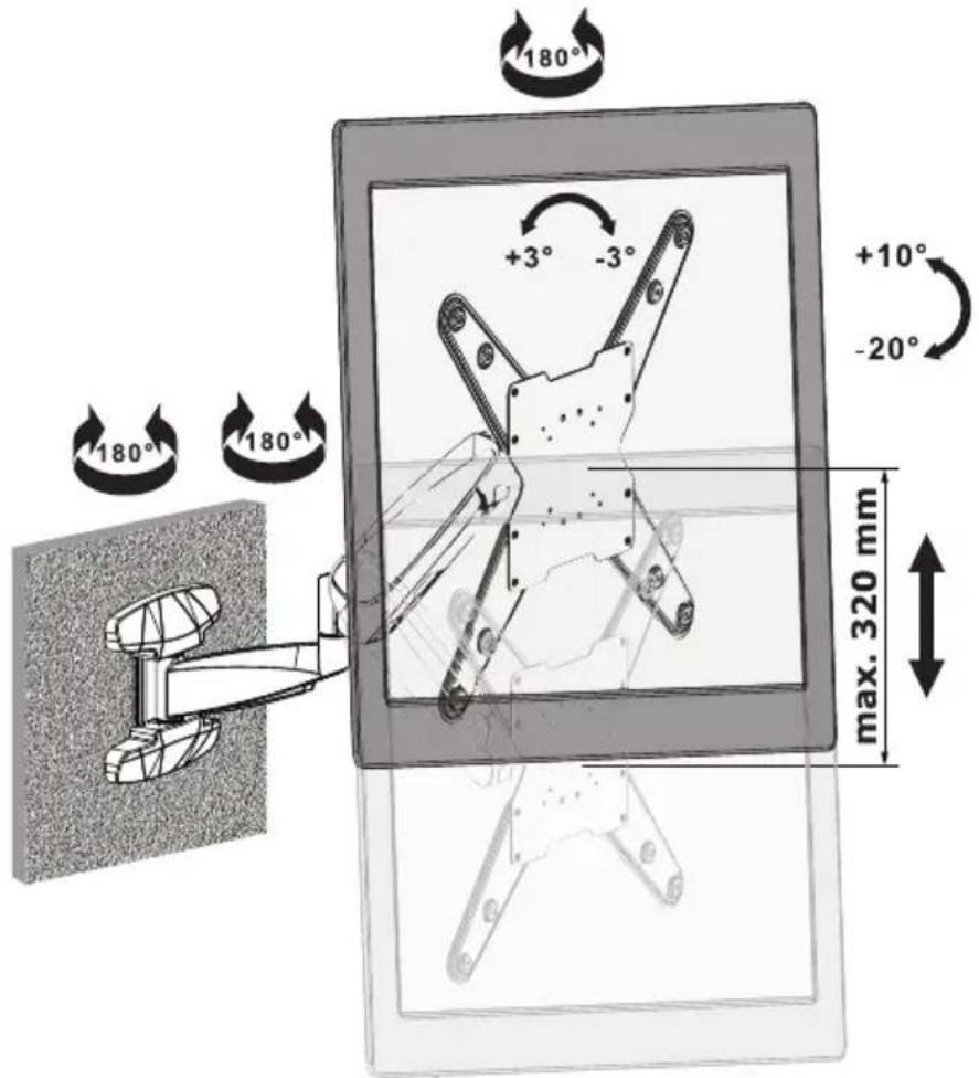
| Distance au mur maximale | 320 mm |
| Angle d'inclinaison | +10° / -20° |
| Rotation horizontale | 180° |
| Nivellement | ±3° |
| Poids du support | Environ 2 kg |
| Couleur | Noir |
| Contenu de l'emballage | Support mural, kit de montage (vis, chevilles, rondelles), notice |
| Types de vis incluses | M5×14, M6×14, M6×30, M8×30, M8×50 |
| Chevilles murales incluses | D5, D8 |
| Garantie | 2 ans |
| Service client | Hotline +49 9101 702-299, info@schwaiger.de |
| Entretien et nettoyage | Nettoyer avec un chiffon sec et non abrasif |
| Sécurité | Vérifier la solidité du mur, utiliser les chevilles adaptées au matériau du mur |
| Pièces détachées et réparabilité | Pièces disponibles sur demande auprès du fabricant |
FOIRE AUX QUESTIONS - LWHD5530 511 Schwaiger
Questions des utilisateurs sur LWHD5530 511 Schwaiger
0 question sur cet appareil. Repondez a celles que vous connaissez ou posez la votre.
Poser une nouvelle question sur cet appareil
Téléchargez la notice de votre Support mural au format PDF gratuitement ! Retrouvez votre notice LWHD5530 511 - Schwaiger et reprennez votre appareil électronique en main. Sur cette page sont publiés tous les documents nécessaires à l'utilisation de votre appareil LWHD5530 511 de la marque Schwaiger.
MODE D'EMPLOI LWHD5530 511 Schwaiger
natural_image
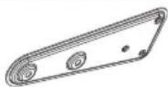
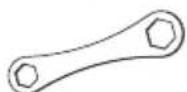
Mechanical arm mounted on a wall-mounted device, showing four articulated arms with mounting holes (no text or symbols visible)B (2x)
C (8x)
D (2x)
A (1x)
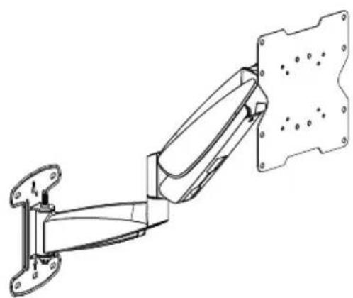
natural_image
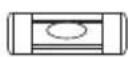
Technical line drawing of a mechanical arm assembly with mounting flanges (no text or symbols)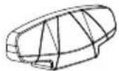

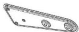
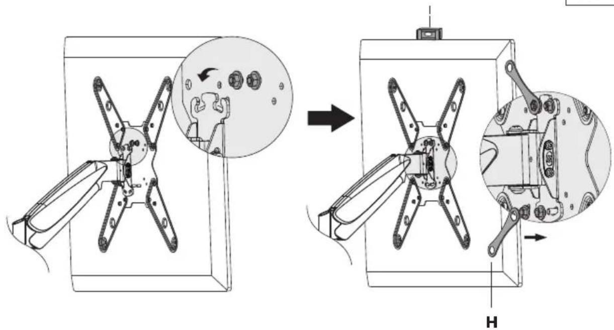
I (1x)
H (1x)
M-D (4x)
M-E (4x)
M-F (4x)
M-A (4x)
M-B (4x)
M-C (4x)

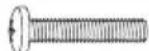
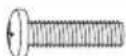
M5x14 M6x14 M6x30 M8x30 M8x50 D5


W-A (5x)
W-B (5x)
W-C (5x)
M-G (4x)
M-H (8x)
M-I (8x)

D8


SX10×50

1
text_image
Technical diagram illustrating mechanical assembly steps with labeled components and directional arrows indicating motion.2A
text_image
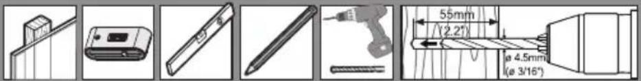
Technical diagram showing various mechanical and electrical components with dimensional annotations in millimeters and inches.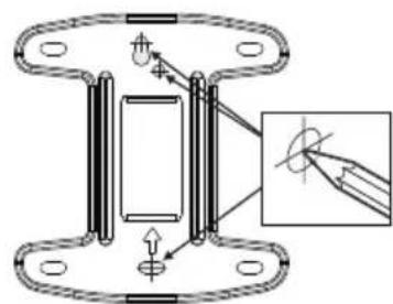
text_image
Technical diagram showing a mechanical assembly with labeled components and an inset magnified view of a pin or pin alignment.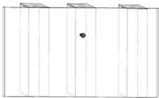
natural_image
Pure architectural line drawing of a building facade with vertical supports and a central circular feature (no text or symbols)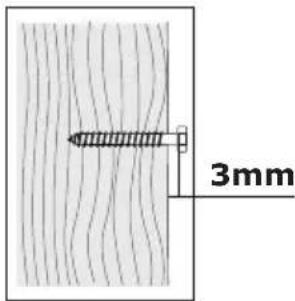
text_image
3mm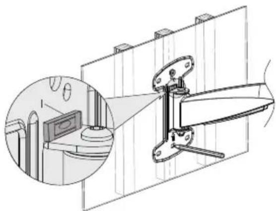
natural_image
Technical line drawing of a kitchen appliance with a close-up inset showing a magnified view of the interior (no text or symbols)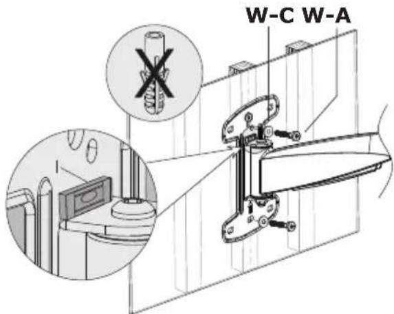
text_image
W-C W-A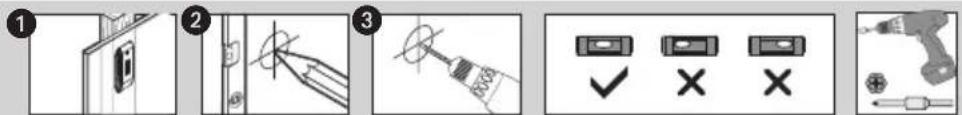
text_image
Diagram showing five-step installation or repair process with labeled steps and icons for inspection, repair, and tool installation.2B
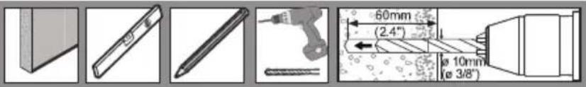
text_image
60mm (2.4") Ø 10mm (ø 3/8")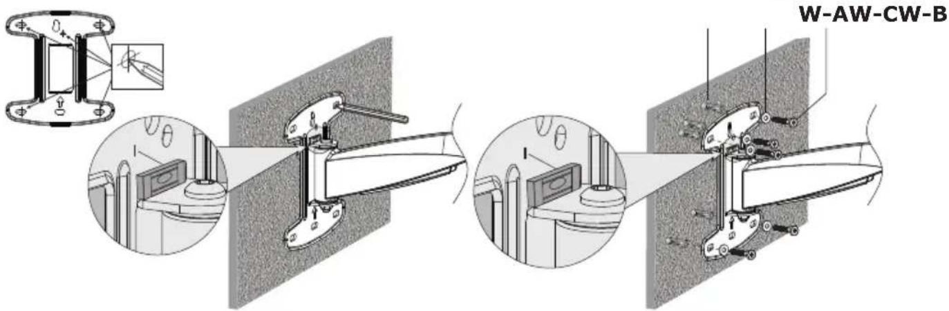
text_image
W-AW-CW-B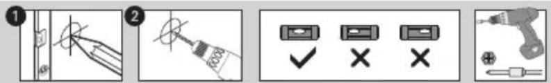
text_image
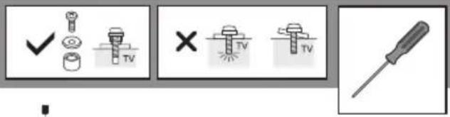
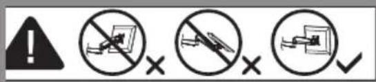
Diagram showing four different electrical or mechanical tool icons with labels and check/cancel buttons3
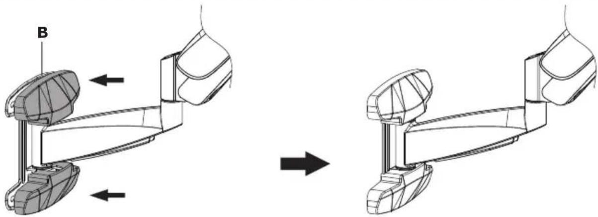
natural_image
Technical line drawing of a mechanical assembly before and after assembly, showing two stages with no text or symbols4
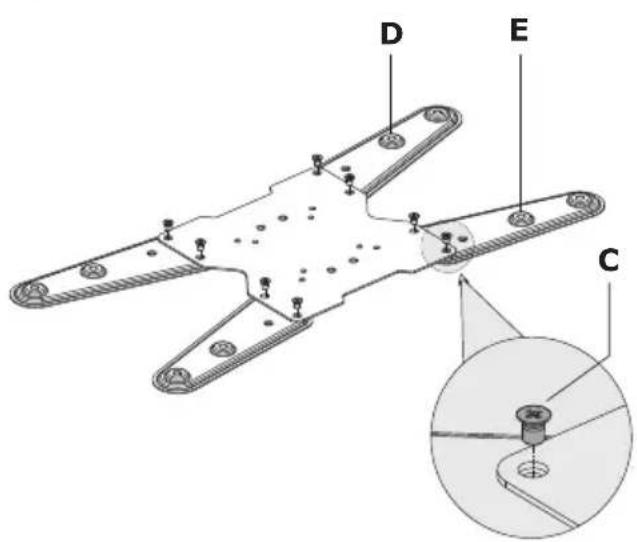
text_image
D E C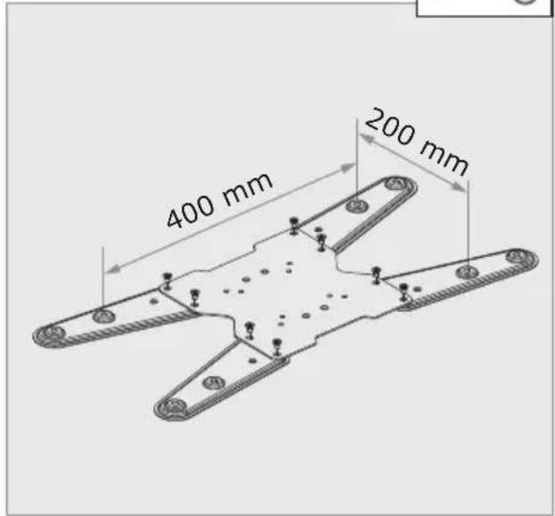
text_image
400 mm 200 mm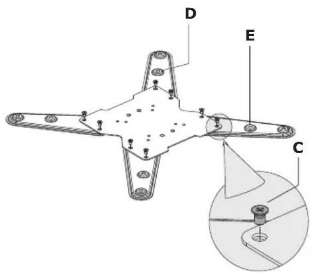
text_image
D E C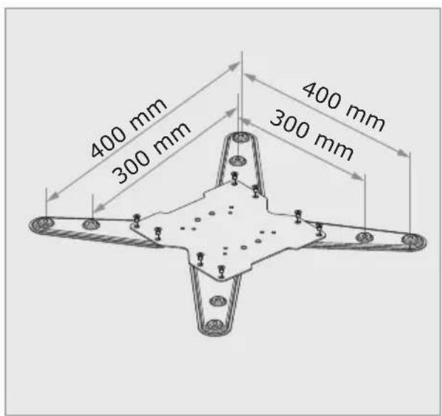
text_image
400 mm 300 mm 400 mm 300 mm5A
text_image
Diagram showing four different types of screw or screw tools with check, cross, and pencil tool icons, likely illustrating a precision or inspection process.
text_image
M-A M-F M-B M-G5B
text_image
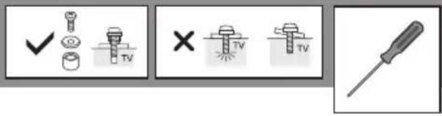
Diagram showing four different types of screwdriver tool icons: check, cross, and screwdriver with TV labels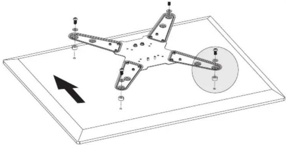
natural_image
Technical line drawing of a mechanical assembly with mounting holes and a circular component, no text or symbols present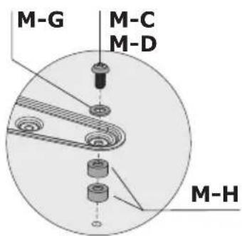
text_image
M-G M-C M-D M-H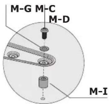
text_image
M-G M-C M-D M-I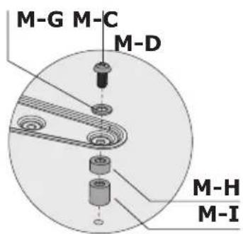
text_image
M-G M-C M-D M-H M-I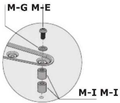
text_image
M-G M-E M-I M-I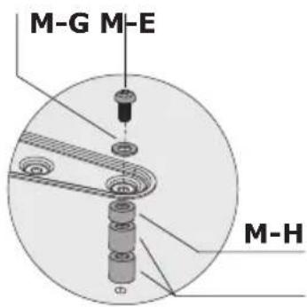
text_image
M-G M-E M-H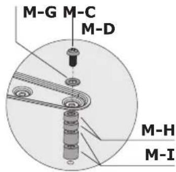
text_image
M-G M-C M-D M-H M-I6
natural_image
Technical illustration of a mechanical assembly with exploded and assembled views, showing components like gears and levers (no text or symbols)7
text_image
!
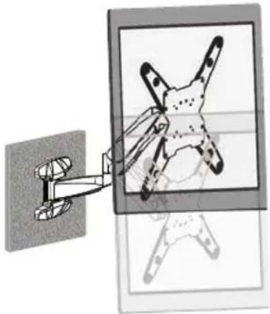
natural_image
Diagram showing a mechanical assembly with a star-shaped component mounted on a wall, alongside a separate view of a mechanical assembly (no text or symbols present)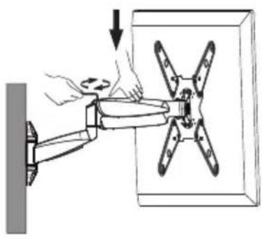
natural_image
Diagram of a hand holding a wall-mounted device next to a multi-pole motor, with an arrow indicating rotation (no text or symbols present)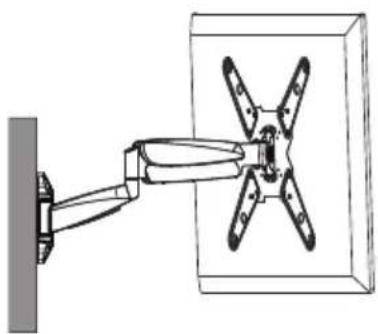
natural_image
Technical line drawing of a mechanical assembly with four blades mounted on a wall (no text or symbols)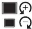
natural_image
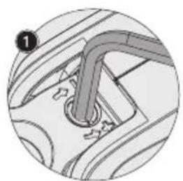
Mechanical component diagram showing a curved pipe inserted into a car's side panel (no text or symbols)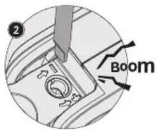
text_image
Boom8
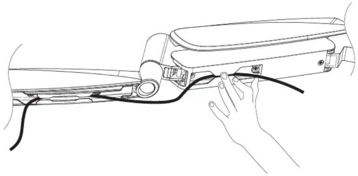
natural_image
Line drawing of a hand connecting a cable to a device component (no text or symbols)9
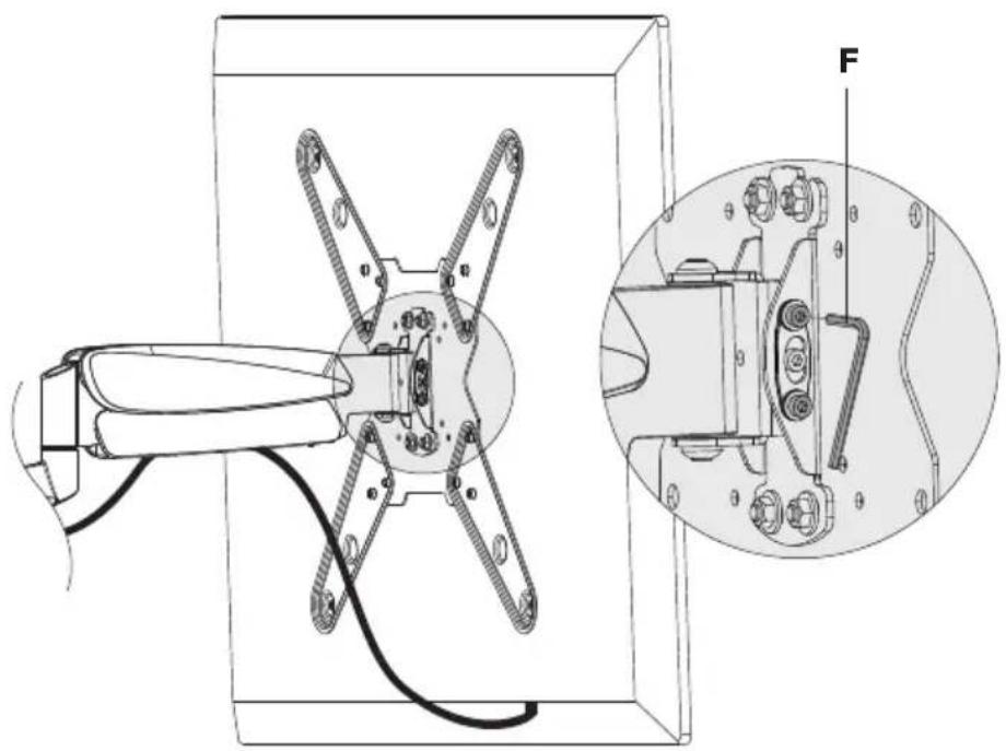
natural_image
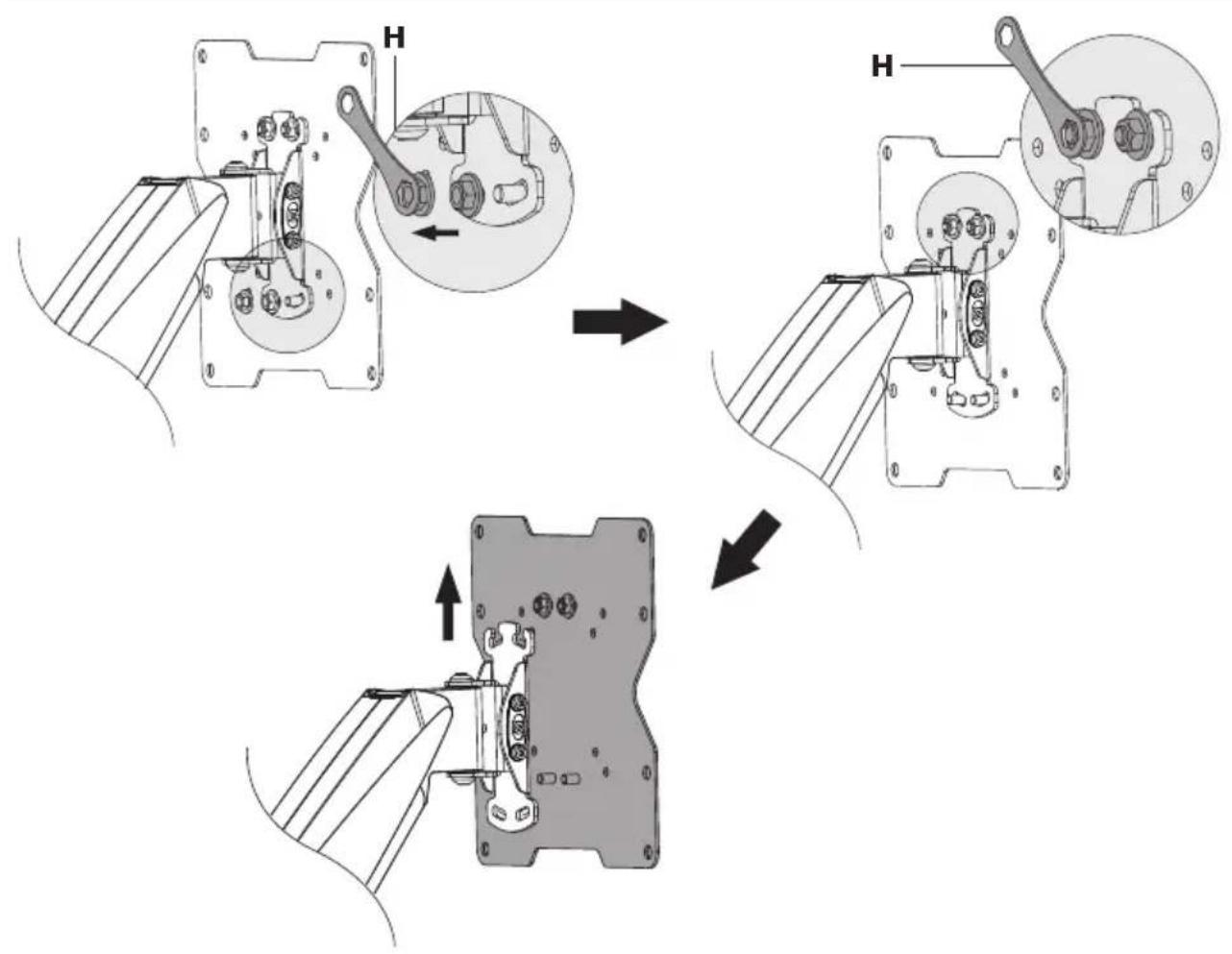
Technical line drawing of a mechanical assembly with an inset close-up showing internal components (no text or symbols)10
text_image
180° +3° -3° +10° -20° max. 320 mmHotline +49 9101 702-299
SCHWAIGER®
Schwaiger GmbH
Würzburger Straße 17
90579 Langenzenn
www.schwaiger.de
info@schwaiger.de