
KM-515MRH - Machine à glace Hoshizaki - Notice d'utilisation et mode d'emploi gratuit
Retrouvez gratuitement la notice de l'appareil KM-515MRH Hoshizaki au format PDF.

| Type de produit | Machine à glace modulaire |
| Marque | Hoshizaki |
| Modèle | KM-515MRH |
| Production de glace | Glaçons en forme de croissant (jusqu'à 230 kg par jour) |
| Dimensions (L x P x H) | Environ 762 x 610 x 810 mm (sans emballage) |
| Poids net | Environ 75 kg |
| Alimentation électrique | 115 V / 60 Hz, 208-230 V / 60 Hz (selon configuration) |
| Type de condenseur | Refroidi par air (modèle MRH) |
| Réfrigérant | R-404A |
| Commandes | Commande électronique avec cycle automatique de récolte |
| Capacité du bac de stockage | Environ 80 kg (selon accessoires) |
| Entretien et nettoyage | Nettoyage régulier du circuit d'eau, du condenseur et du filtre à air recommandé tous les 6 mois |
| Sécurité | Interrupteur de niveau de glace mécanique, protection thermique du compresseur |
| Pièces principales | Compresseur, condenseur, évaporateur, pompe à eau, vanne d'eau, détendeur |
| Accessoires inclus | Bac à glace, panier, filtre à air, notice d'installation |
| Réparabilité | Pièces détachées disponibles auprès de Hoshizaki |
FOIRE AUX QUESTIONS - KM-515MRH Hoshizaki
Questions des utilisateurs sur KM-515MRH Hoshizaki
0 question sur cet appareil. Repondez a celles que vous connaissez ou posez la votre.
Poser une nouvelle question sur cet appareil
Téléchargez la notice de votre Machine à glace au format PDF gratuitement ! Retrouvez votre notice KM-515MRH - Hoshizaki et reprennez votre appareil électronique en main. Sur cette page sont publiés tous les documents nécessaires à l'utilisation de votre appareil KM-515MRH de la marque Hoshizaki.
MODE D'EMPLOI KM-515MRH Hoshizaki
Hoshizaki America, Inc.
Modular Crescent Cuber
Models
KM-515MAH
KM-515MWH
KM-515MRH

text_image
HOSHIZAKI AMERICA, INC. TM"A Superior Degree of Reliability"
www.hoshizaki.com
PARTS LIST

Number: 71274
Issued: 1-28-2008
Revised: 2-24-2015
CONTENTS
Auxiliary Codes....3
Note About Ordering Parts 4
A. Main Assembly & Refrigeration Circuit 5
KM-515MAH 5
KM-515MWH....7
KM-515MRH....9
B. Water Circuit....11
C. Control Box Assembly 14
D. Accessories & Labels 16
Auxiliary Codes
| KM-515MAH S-0 October 2007 | KM-515MWH S-0 November 2007 | ||||
| T-0 | April | 2008 | T-0 | February 2008 | |
| U-1 | January | 2009 | U-1 | January 2009 | |
| U-2 | February | 2009 | U-2 | February 2009 | |
| U-3 | August | 2009 | U-3 | August 2009 | |
| V-0 | January | 2010 | V-0 | January 2010 | |
| V-1 | March | 2010 | V-1 | March 2010 | |
| V-2 | April | 2010 | V-2 | April 2010 | |
| V-3 | August | 2010 | V-3 | August 2010 | |
| A-0 | January | 2011 | A-0 | January 2011 | |
| B-0 | January | 2012 | B-0 | January 2012 | |
| B-1 | March | 2012 | B-1 | May 2012 | |
| C-0 | January | 2013 | C-0 | January 2013 | |
| C-1 | May | 2013 | C-1 | April 2013 | |
| C-2 | October | 2013 | C-2 | May 2013 | |
| D-0 | January | 2014 | C-3 | October 2013 | |
| D-1 | December | 2014 | D-0 | January 2014 | |
| E-0 | January | 2015 | D-1 | December 2014 | |
| E-0 | January 2015 | ||||
KM-515MRH S-0 October 2007
| T-0 | May | 2008 |
| T-1 | October | 2008 |
| U-1 | January | 2009 |
| U-2 | February | 2009 |
| U-3 | August | 2009 |
| V-0 | January | 2010 |
| V-1 | March | 2010 |
| V-3 | August | 2010 |
| A-0 | January | 2011 |
| B-0 | January | 2012 |
| B-1 | May | 2012 |
| C-0 | January | 2013 |
| C-1 | May | 2013 |
| D-0 | January | 2014 |
| D-1 | June | 2014 |
| D-2 | December | 2014 |
| E-0 | January | 2015 |
Auxiliary Code Breakdown
The auxiliary code is the first two characters in the serial number. The first character indicates the year. Years progress or regress in alphabetical order. The series runs from "A" through "V" and the letters "I" and "O" are skipped. The second character indicates significant part changes within a year. Base is "0" and this number advances for each change. In cases where there is a letter in parentheses, this designates the month. This is the last character in the serial number. The series runs from "(A)" through "(M)" and the letter "(I)" is skipped. This designation is only included when identifying a parts change within an auxiliary code.
Note About Ordering Parts
Most assemblies cannot be ordered as complete units; parts in the assemblies generally must be ordered separately.
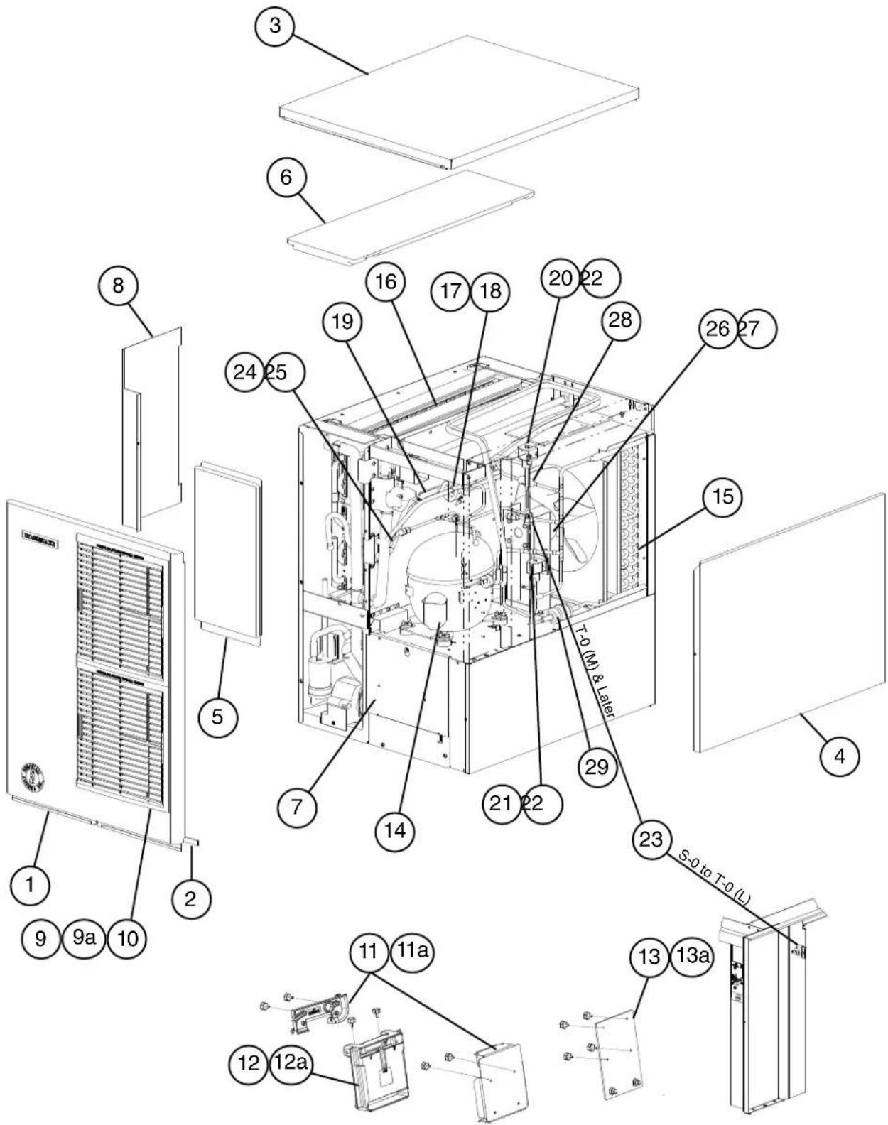
A. Main Assembly & Refrigeration Circuit
KM-515MAH
S-0 to E-0
text_image
Exploded view diagram of a refrigerator internal structure with numbered components and labeled parts| Title: A. Main Assembly & Refrigeration Circuit Model: KM-515MAH | ||||||||||||
| Index No. | Description | Material or Model Number | Part Number | Required Number | ||||||||
| S-0 to T-0 (L) | T-0 (M) to U-1 | U-2 to B-0 | B-1 to C-0 | C-1 to E-0 | ||||||||
| Main Assembly | ||||||||||||
| 1 Front Panel 2A3767G01 1 1 1 1 1 | ||||||||||||
| 2 Basket L=554 mm 4A0808L02 1 1 1 | 1 1 | |||||||||||
| 3 Top Panel 3A3878A01 1 1 1 1 1 | ||||||||||||
| 4 Right Side Panel 2A2117G01 1 1 1 1 | 1 1 | |||||||||||
| 5 Front Insulation | 21 | 5731G01 1 1 1 | 1 1 | |||||||||
| 6 Top Insulation | 21 | 5730G01 1 1 1 | 1 1 | |||||||||
| 7 Base Cover | 32 | 525G01 1 1 1 | 1 1 | |||||||||
| 8 Control Box Cover | 3A | 2476-01 | 1 | 1 1 | 1 | |||||||
| 9 Louver | 1A | 0547-01 | 2 | 2 2 | 2 | |||||||
| 9a Push Retainer | 4A2414-01 | 6 | 6 | 6 6 6 | ||||||||
| 10 Air Filter | 2A2062G01 | 2 | 2 | 2 | 2 | 2 | 2 | |||||
| 11 Bulb Holder | 3A3903-01 | 1 | 1 | - | ||||||||
| Mechanical Bin Control Switch Mount | 3A4463-01 | 1 1 | - | |||||||||
| 3A6040-01 | 1 | |||||||||||
| 11a Thumbscrew | 415949G11 | 2 | 2 | - | ||||||||
| 415949G10 | 2 2 | 2 | ||||||||||
| 12 Mechanical Bin Control | 2A4393G01 | 1 | 1 | 1 | ||||||||
| 12a Thumbscrew | 4 | 5949G10 | 2 2 2 | |||||||||
| 13 Mechanical Bin Control Extension Bracket | 4A5046G01 | 1 1 | 1 | |||||||||
| 13a Thumbscrew | 4 | 5949G10 | 4 4 4 | |||||||||
| Refrigeration Circuit | ||||||||||||
| 14 Compressor | 4A4376-01 | 1 | 1 | 1 | 1 | 1 | ||||||
| 15 Condenser | 2A3756-01 | 1 | 1 | 1 | 1 | 1 | ||||||
| 16 Evaporator | 106492G01 | 1 | 1 | 1 | - | |||||||
| 1A2357G01 | 1 1 | |||||||||||
| 17 Thermostatic Expansion Valve | 4A4008-01 | 1 | 1 | 1 | 1 | 1 | ||||||
| 18 Thermostatic Expansion Valve Cover | 3A0944-01 | 1 1 | 1 1 1 | |||||||||
| 19 Thermostatic Expansion Valve Bulb Holder | 3A0107-01 | 1 1 | 1 1 1 | |||||||||
| 20 Hot Gas Valve Body | 4A3978-01 | 1 | 1 | 1 | 1 | 1 | ||||||
| 21 Liquid Line Valve Body | 4A3276-01 | 1 | 1 | 1 | 1 | 1 | ||||||
| 22 Valve Coil | 4A3277-01 | 2 2 | 2 2 2 | |||||||||
| 23 High-Pressure Switch | 433441-07 | 1 | - | |||||||||
| 463180-04 | 1 1 | 1 1 | ||||||||||
| 24 Thermistor | 429006-03 | 1 1 | 1 1 1 | |||||||||
| 25 Thermistor Holder | 427430-01 | 1 | 1 | 1 | 1 | 1 | ||||||
| 26 Fan Motor | 4A3158-01 | 1 1 | 1 1 1 | |||||||||
| 27 Fan Blade | 4A3959-01 | 1 1 | 1 1 1 | |||||||||
| 28 Strainer | 441569-01 | 1 1 | 1 1 1 | |||||||||
| 29 Drier | 4A2666-01 | 1 1 | 1 1 1 | |||||||||
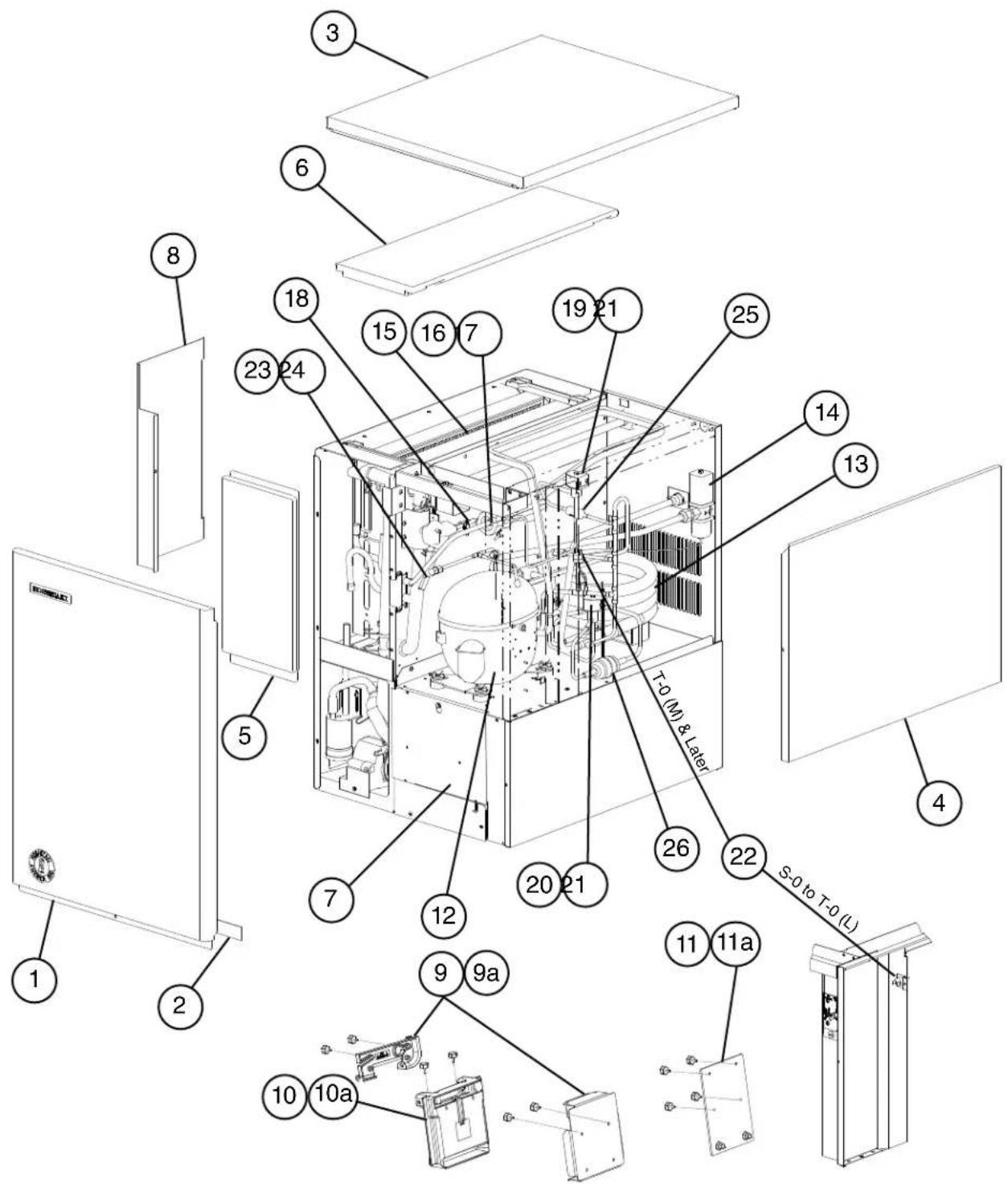
A. Main Assembly & Refrigeration Circuit KM-515MWH
S-0 to E-0
text_image
Exploded view diagram of a refrigerator internal structure with numbered components and labeled parts| Title: A. Main Assembly & Refrigeration Circuit Model: KM-515MWH | |||||||||||
| Index No. | Description | Material or Model Number | Part Number | Required Number | |||||||
| S-0 to T-0 (L) | T-0 (M) to U-1 | U-2 to C-0 | C-1 | C-2 to E-0 | |||||||
| Main Assembly | |||||||||||
| 1 Front Panel 2A2150G01 1 1 1 1 1 | |||||||||||
| 2 Basket L=554 mm 4A0808L02 1 1 1 1 1 1 | |||||||||||
| 3 Top Panel 3A3878A01 1 1 1 1 1 | |||||||||||
| 4 Right Side Panel | 2A | 2117G01 1 1 1 | 1 1 | ||||||||
| 5 Front Insulation | 21 | 5731G01 1 1 1 | 1 1 | ||||||||
| 6 Top Insulation | 21 | 5730G01 1 1 1 | 1 1 | ||||||||
| 7 Base Cover | 32 | 525G01 1 1 1 | 1 1 | ||||||||
| 8 Control Box Cover | 3A | 2476-01 | 1 1 1 | 1 | |||||||
| 9 Bulb Holder | 3A | 3903-01 | 1 | - | |||||||
| 3A4463-01 | 1 1 | - | |||||||||
| 3A6040-01 | 1 | ||||||||||
| 9a | Thumbscrew | 415949G11 | 2 | 2 | - | ||||||
| 415949G10 | 2 2 | 2 | |||||||||
| 10 | Mechanical Bin Control | 2A4393G01 | 1 | 1 | 1 | ||||||
| 10a Thumbscrew | 4 | 5949G10 | 2 2 2 | ||||||||
| 11 | Mechanical Bin Control Extension Bracket | 4A5046G01 | 1 1 | 1 | |||||||
| 11a | Thumbscrew | 415949G10 | 4 | 4 | 4 | ||||||
| Refrigeration Circuit | |||||||||||
| 12 | Compressor | 4A4376-01 | 1 | 1 | 1 | 1 | 1 | ||||
| 13 | Condenser | HS-0160 | 2A2359G01 | 1 | 1 | 1 | - | ||||
| 3A7321-01 | 1 1 | ||||||||||
| 14 | Water Regulating Valve | 4A0911-06 | 1 | 1 | 1 | 1 | 1 | ||||
| 15 | Evaporator | 106492G01 | 1 | 1 | 1 | 1 | 1 | ||||
| 16 | Thermostatic Expansion Valve | 4A4008-01 | 1 | 1 | 1 | 1 | 1 | ||||
| 17 | Thermostatic Expansion Valve Cover | 3A0944-01 | 1 1 | 1 1 1 | |||||||
| 18 | Thermostatic Expansion Valve Bulb Holder | 3A0107-01 | 1 1 | 1 1 1 | |||||||
| 19 | Hot Gas Valve Body | 4A3978-01 | 1 | 1 | 1 | 1 | 1 | ||||
| 20 | Liquid Line Valve Body | 4A3276-01 | 1 | 1 | 1 | 1 | 1 | ||||
| 21 | Valve Coil | 4A3277-01 | 2 2 | 2 2 2 | |||||||
| 22 | High-Pressure Switch | 433441-05 | 1 | - | |||||||
| 463180-05 | 1 1 | 1 1 | |||||||||
| 23 | Thermistor | 429006-03 | 1 1 | 1 1 1 | |||||||
| 24 | Thermistor Holder | 427430-01 | 1 | 1 | 1 | 1 | 1 | ||||
| 25 | Strainer | 441569-01 | 1 1 | 1 1 1 | |||||||
| 26 | Drier | 4A2666-01 | 1 1 | 1 1 1 | |||||||
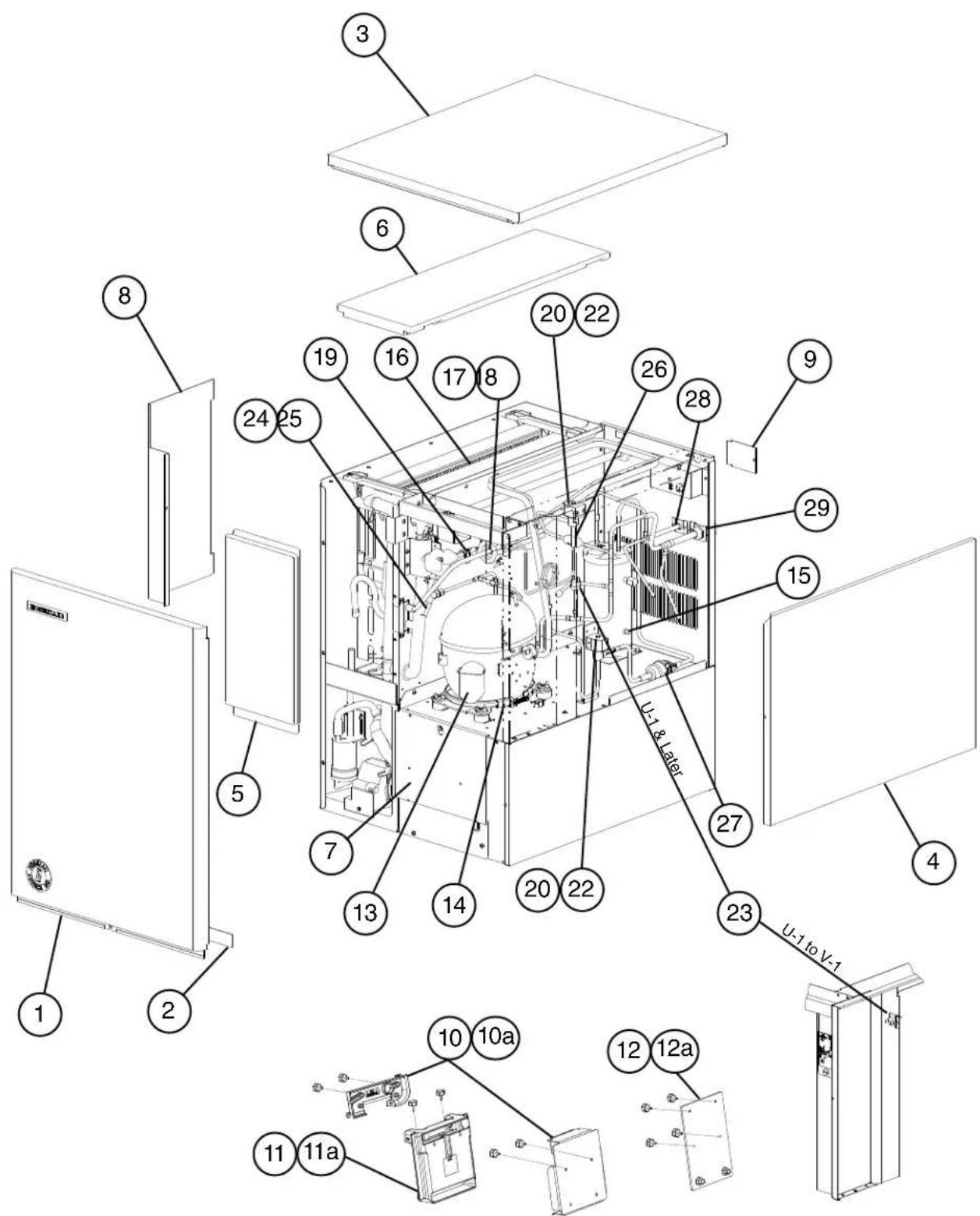
A. Main Assembly & Refrigeration Circuit
KM-515MRH
S-0 to E-0
text_image
Exploded view diagram of a refrigerator internal structure with numbered components and labeled parts| Title: A. Main Assembly & Refrigeration Circuit Model: KM-515MRH | |||||||||||
| Index No. | Description | Material or Model Number | Part Number | Required Number | |||||||
| S-0 to T-1 U | U-1 | U-2 to V-3 (K) | V-3 (L) to C-0 | C-1 to E-0 | |||||||
| Ice Cuber Assembly | |||||||||||
| 1 Front Panel 2A2150G01 1 1 1 1 1 | |||||||||||
| 2 Gasket L=554 mm 4A0808L02 1 1 1 1 | 1 | ||||||||||
| 3 Top Panel | 3A3878A01 | 1 1 1 | 1 | ||||||||
| 4 Right Side Panel | 2A2117G01 | 1 1 1 | 1 | ||||||||
| 5 Front Insulation | 215731G01 1 1 | 1 1 | |||||||||
| 6 Top Insulation | 215730G01 1 1 | 1 1 | |||||||||
| 7 Base Cover | 321525G01 1 1 | 1 1 | |||||||||
| 8 Control Box Cover | 3A2476-01 | 1 1 1 | 1 | ||||||||
| 9 Junction Box Cover | 433410-01 | 1 1 1 | 1 | ||||||||
| 10 Bulb Holder | 3A3903-01 | 1 | 1 | - | |||||||
| Mechanical Bin Control Switch Mount | 3A4463-01 | 1 1 | - | ||||||||
| 3A6040-01 | 1 | ||||||||||
| 10a Thumbscrew | 415949G11 | 2 | 2 | - | |||||||
| 415949G10 | 2 2 | 2 | |||||||||
| 11 Mechanical Bin Control | 2A4393G01 | 1 | 1 | 1 | |||||||
| 11a Thumbscrew | 415949G10 | 2 | 2 | 2 | |||||||
| 12 Mechanical Bin Control Extension Bracket | 4A5046G01 | 1 1 | 1 | ||||||||
| 12a Thumbscrew | 415949G10 | 4 4 4 | |||||||||
| Refrigeration Circuit | |||||||||||
| 13 Compressor | 4A4376-01 | 1 | 1 | 1 | 1 | 1 | |||||
| 14 Crankcase Heater | 3A4663-01 | 1 | 1 | 1 | - | ||||||
| 4A5091-01 | 1 1 | ||||||||||
| 15 Receiver Tank | 437596-01 | 1 | 1 | 1 | 1 | 1 | |||||
| 16 Evaporator | 106492G01 | 1 | 1 | 1 | 1 | 1 | |||||
| 17 Thermostatic Expansion Valve | 4A1414-01 | 1 | 1 | 1 | 1 | 1 | |||||
| 18 Thermostatic Expansion Valve Cover | 3A0944-01 | 1 1 | 1 1 | ||||||||
| 19 Thermostatic Expansion Valve Bulb Holder | 3A0107-01 | 1 1 | 1 1 | ||||||||
| 20 Hot Gas Valve Body | 4A3978-01 | 1 | 1 | 1 | 1 | 1 | |||||
| 21 Liquid Line Valve Body | 4A3276-01 | 1 | 1 | 1 | 1 | 1 | |||||
| 22 Valve Coil | 4A3277-01 | 2 2 | 2 2 2 | ||||||||
| 23 High-Pressure Switch | 433441-07 | 1 | - | ||||||||
| 463180-04 | 1 1 | 1 1 | |||||||||
| 24 Thermistor | 429006-03 | 1 1 | 1 1 | ||||||||
| 25 Thermistor Holder | 427430-01 | 1 | 1 | 1 | 1 | 1 | |||||
| 26 Strainer | 441569-01 | 1 1 | 1 1 | ||||||||
| 27 Drier | 4A2666-01 | 1 1 | 1 1 | ||||||||
| 28 Liquid Line Coupling | 4A3972G01 | 1 | 1 | 1 | 1 | 1 | |||||
| 29 Discharge Line Coupling | 434136G01 1 | 1 1 1 | 1 | ||||||||
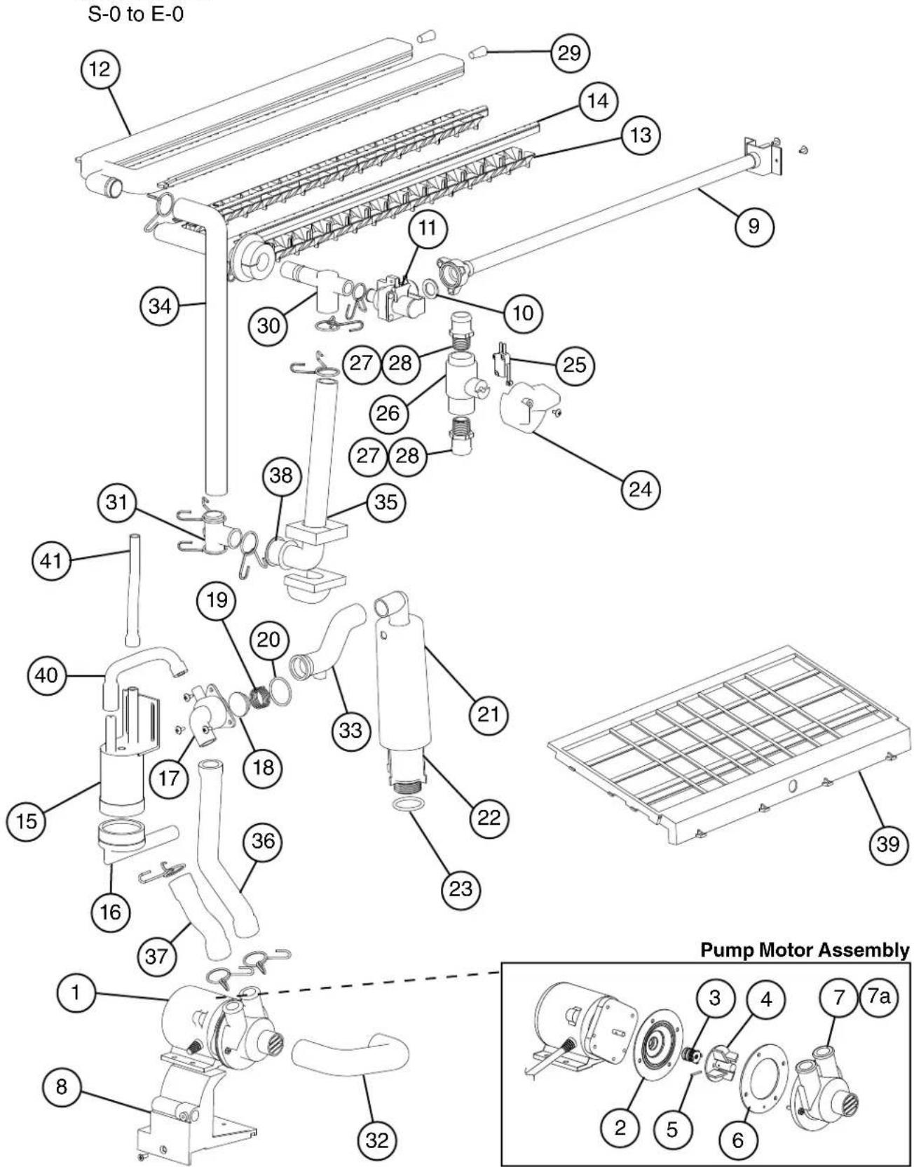
B. Water Circuit
KM-515M_H
text_image
S-0 to E-0 12 29 14 13 9 34 30 11 10 27 28 25 26 27 28 24 38 35 31 41 19 20 33 21 40 17 18 36 22 23 15 16 37 1 1 8 32 Pump Motor Assembly 39 2 5 6 7 7a| Title: B. Water Circuit Model: KM-515M_H | |||||||||||
| Index No. | Description | Material or Model Number | Part Number | Required Number | |||||||
| S-0 to V-3 | A-0 B-0 | B-1 to E-0 | |||||||||
| 1 Pump Motor Assembly (includes items 2 through 7a) | PA0613 1 1 1 | ||||||||||
| 2 Pump Flange 3A2988-01 1 1 1 | |||||||||||
| 3 Mechanical Seal 465627-01 1 1 1 | |||||||||||
| 4 Impeller 433522-01 1 1 1 | |||||||||||
| 5 Pir | 4A0648-01 1 1 1 | ||||||||||
| 6 Pump Gasket | 4A2974-01 1 1 1 | ||||||||||
| 7 Pump Housing | 211409-01 | 1 1 | |||||||||
| 7a | Screw | 4x20 | 4A3871-01 | 4 | 4 | 4 | |||||
| 8 Pump Motor Bracket | 211408-01 | 1 1 1 | |||||||||
| 9 Water Supply Pipe | 4A0768G04 1 | - | |||||||||
| 4A5216G04 | 1 1 | ||||||||||
| 10 | Rubber Gasket | 413854-03 | 1 | 1 | 1 | ||||||
| 11 | Inlet Water Valve | KM-515MAH | 3U0111-04 | 1 | 1 | - | |||||
| 3U0111-03 | 1 | ||||||||||
| KM-515MWH KM-515MRH | 3U0111-04 | 1 | 1 | ||||||||
| 12 | Spray Tube | 1A0260-02 | 1 | 1 | 1 | ||||||
| 13 | Spray Guide | KM-515MAH | 208586-01 | 6 | 6 | - | |||||
| 2A4282-02 | 2 | ||||||||||
| KM-515MWH KM-515MRH | 208586-01 6 | 6 | |||||||||
| 14 | Water Supply Tube | 2A0079-01 | 1 | 1 | 1 | ||||||
| 15 | Float Switch | 4A3624-01 1 | 1 1 | ||||||||
| 16 | Float Switch Connector | 426799-01 | 1 | 1 | 1 | ||||||
| 17 | Drain Valve Housing | 321001-01 | 1 | 1 | 1 | ||||||
| 18 | Drain Valve Seat | 433705-01 | 1 | 1 | 1 | ||||||
| 19 | Drain Valve Spring | 322110-01 | 1 | 1 | 1 | ||||||
| 20 | Drain Valve O-Ring | 7611-G035 | 1 | 1 | 1 | ||||||
| 21 | Overflow Cap | 321002-01 | 1 1 | 1 | |||||||
| 22 | Overflow Pipe | 430722-03 | 1 1 | 1 | |||||||
| 23 | Overflow Pipe O-Ring | 4A1234-01 | 1 1 | 1 | |||||||
| 24 | Cleaning Valve Handle | 215383-01 | 1 | 1 | 1 | ||||||
| 25 | Cleaning Valve Microswitch | 4A2546-01 | 1 | 1 | 1 | ||||||
| 26 | Cleaning Valve Ball Valve | 439293-01 | 1 | 1 | 1 | ||||||
| 27 | Cleaning Valve Male Adaptor | 325826-01 | 2 | 2 | 2 | ||||||
| 28 | Cleaning Valve O-Ring | 7611-P018 | 2 | Replaced with thread sealant tape | |||||||
| 29 | Spray Tube Plug | 4A0176-01 | 2 | 2 | 2 | ||||||
| 30 | Tee | 4A0177-01 | 1 | 1 | 1 | ||||||
| 31 | Distributor | 432426-01 1 | 1 1 | ||||||||
| 32 | Suction Hose | 433466-01 1 | 1 1 | ||||||||
| 33 | Drain Hose | 433468-01 1 | 1 1 | ||||||||
| 34 | Rubber Hose C | 4A1551-03 | 1 1 | 1 | |||||||
| 35 | Rubber Hose D | 4A1551-04 | 1 1 | 1 | |||||||
| 36 | Vinyl Hose | L=250 mm | 7716-2025 | 1 | 1 | 1 | |||||
| 37 | Vinyl Hose | L=110 mm | 7716-2025 | 1 | 1 | 1 | |||||
| 38 | Rubber Ring 439236-01 1 1 1 | ||||||||||
| 39 | Cube Guide | 212088-01 | 1 1 | 1 | |||||||
| 40 Silicone Hose L=140 mm 7730I3896 | 1 1 1 | ||||||||||
| 41 Silicone Hose L=140 mm 7730I3812 | 1 1 1 | ||||||||||
| Hose Clamp 25 mm 427443-03 9 | 9 9 | ||||||||||
| Hose Clamp 18 mm 427443-05 1 | 1 1 | ||||||||||
| Hose Clamp 20 mm 427443-06 1 | 1 1 | ||||||||||
C. Control Box Assembly
KM-515M\_H
S-0 to E-0
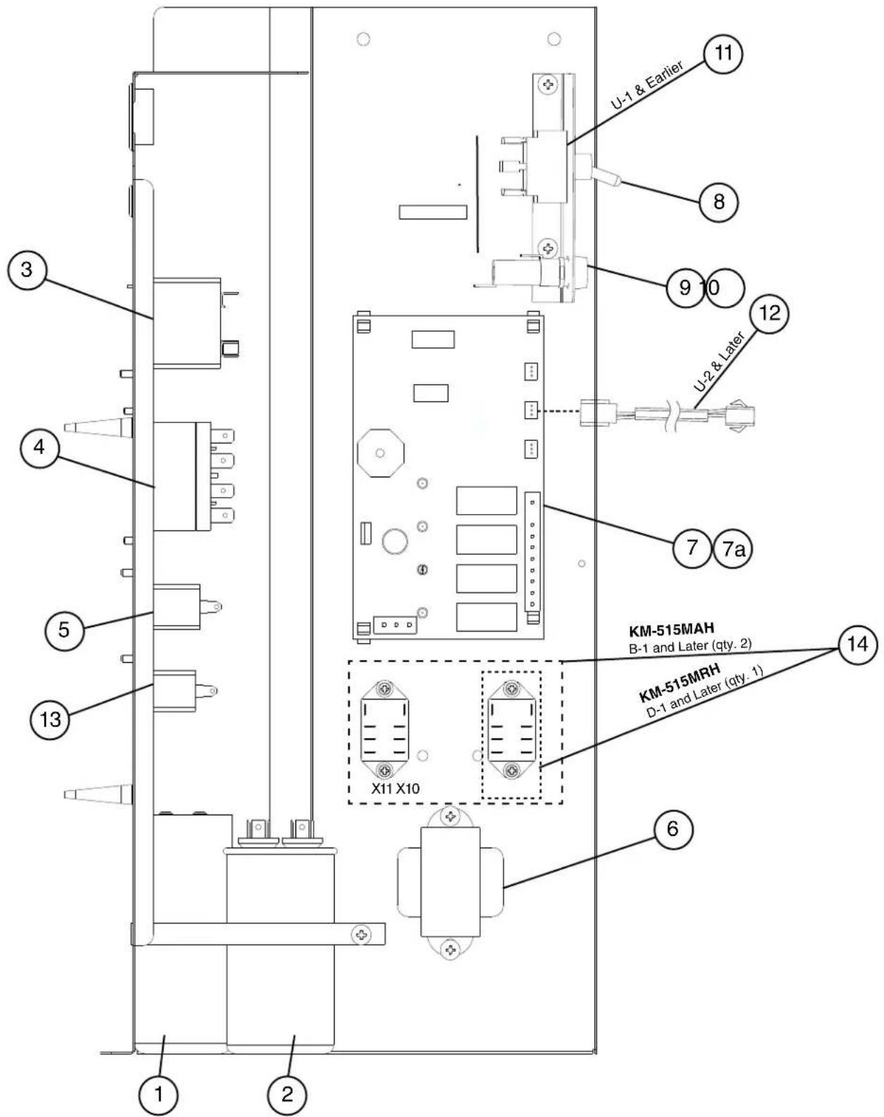
text_image
U-1 & Earlier 11 8 9 10 12 U-2 & Later 7 7a KM-515MAH B-1 and Later (qty. 2) KM-515MRH D-1 and Later (qty. 1) X11 X10 6 1 2 3 4 5 13 1| Title: C. Control Box Assembly Model: KM-515M_H | |||||||||||
| Index No. | Description | Material or Model Number | Part Number | Required Number | |||||||
| S-0 to U-1 | U-2 to V-1 | V-2 to B-0 | B-1 to D-0 | D-1 E-0 | |||||||
| 1 Start Capacitor 243-292MFD, | 165V | 3A0076-20 1 | 1 1 1 | ||||||||
| 2 Run Capacitor 35MFD, | 440VAC | 3A2005-12 1 | 1 1 1 | ||||||||
| 3 Start Relay (Starter) 4A1107-11 1 1 | 1 1 | ||||||||||
| 4 Magnetic Contactor KM-515MAH | KM-515MWH | 428393-01 1 | - | ||||||||
| 4A3140-01 | 1 1 | 1 | |||||||||
| KM-515MRH | 428393-01 | 1 | 1 | - | |||||||
| 4A5096-01 | 1 1 | - | |||||||||
| 4A3140-01 | 1 | ||||||||||
| 5 Pump Motor Capacitor 5.5MFD, 250VAC | 443192-03 | 1 1 | 1 1 1 | ||||||||
| 6 | Control Transformer | 3A0172-01 | 1 | 1 | 1 | 1 | 1 | ||||
| 7 Control Board "E" Board 2A | 1410-01 1 - | ||||||||||
| "G" Board | 2A3792-01 | 1 1 | 1 1 | ||||||||
| 7a | Control Board Support | 4A0336-03 | 4 | 4 | 4 | 4 | |||||
| 8 Control Switch | 443119-01 | 1 1 1 | 4 | ||||||||
| 9 Fuse Holder | 4A5443-01 | 1 1 1 | 1 | ||||||||
| 10 | Fuse | AGC-10A, 250VAC | 4A0893-07 | 1 1 | 1 1 1 | ||||||
| 11 | Bin Control Thermostat | 4A2879-01 | 1 | - | |||||||
| 12 | Mechanical Bin Control Wire Harness | 4A2200G04 | 1 1 | 1 1 | |||||||
| 13 | Fan Motor Capacitor | KM-515MAH 5MFD, 250VAC | 443192-02 | 1 1 | 1 1 1 | ||||||
| 14 | Harvest Pump Timer Relays (X10, X11) | KM-515MAH 406132-07 | 2 2 | ||||||||
| Crankcase Heater Relay (X10) KM-515MRH 406 | 32-07 | 1 | |||||||||
D. Accessories & Labels
KM-515M\_H
S-0 to E-0
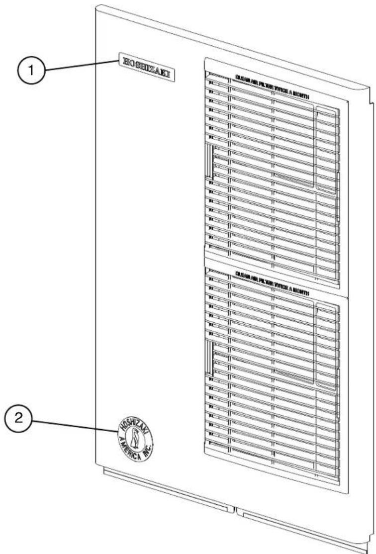
text_image
1 HOSHIZAKI 2 HOSHIZAKI CLOWS PLUGE TINZ A MONTH CLOWS PLUGE TINZ A MONTH HOSHIZAKI AMERICA NEL| Title: D.Accessories & Labels Model: KM-515M_H | |||||||||||
| IndexNo. | Description | Material orModel Number | Part Number | Required Number | |||||||
| S-0toE-0 | |||||||||||
| 1 Hoshizaki Emblem Label 4A0560-01 1 | |||||||||||
| 2 Penguin Label 4A0526-01 1 | |||||||||||
| 3 Universal Brace 4A0363-01 2 | |||||||||||
| 3a Hex Head Bolt 5x12, SS 7B02-0512 2 | |||||||||||