
KMD-530MWH - Machine à glace Hoshizaki - Notice d'utilisation et mode d'emploi gratuit
Retrouvez gratuitement la notice de l'appareil KMD-530MWH Hoshizaki au format PDF.
| Type de produit | Machine à glace professionnelle |
| Marque | Hoshizaki |
| Modèle | KMD-530MWH |
| Production de glace (24h) | Environ 230 kg (510 lb) |
| Type de glace | Glaçons en forme de croissant (crescent) |
| Type de refroidissement | Refroidissement à eau |
| Alimentation électrique | 220-240 V, 50 Hz, monophasé |
| Puissance absorbée | Environ 1,6 kW |
| Dimensions (L x P x H) | 762 x 610 x 800 mm (environ) |
| Poids net | Environ 95 kg |
| Alimentation en eau | Raccordement direct au réseau d'eau (pression min. 1 bar) |
| Capacité du réservoir de stockage | Environ 45 kg |
| Fonctions principales | Production automatique de glace, cycle de récolte, arrêt automatique du bac plein, nettoyage automatique, contrôle électronique |
| Entretien et nettoyage | Nettoyage régulier du circuit d'eau, du condenseur et du filtre à air ; utilisation de solutions de nettoyage Hoshizaki |
| Sécurité | Protection contre la surchauffe du compresseur, protection des circuits électriques, contrôle de niveau d'eau, arrêt automatique en cas de panne |
| Pièces détachées et réparabilité | Liste complète des pièces détachées disponible (voir notice) ; réparabilité assurée par un professionnel agréé Hoshizaki |
| Informations générales | Machine à glace modulaire, raccordement électrique et hydraulique requis, utilisée en restauration et hôtellerie |
FOIRE AUX QUESTIONS - KMD-530MWH Hoshizaki
Questions des utilisateurs sur KMD-530MWH Hoshizaki
0 question sur cet appareil. Repondez a celles que vous connaissez ou posez la votre.
Poser une nouvelle question sur cet appareil
Téléchargez la notice de votre Machine à glace au format PDF gratuitement ! Retrouvez votre notice KMD-530MWH - Hoshizaki et reprennez votre appareil électronique en main. Sur cette page sont publiés tous les documents nécessaires à l'utilisation de votre appareil KMD-530MWH de la marque Hoshizaki.
MODE D'EMPLOI KMD-530MWH Hoshizaki
Parts List
Modular Crescent Cuber
Models
KMD-460MAH, MWH
KMD-530MAH, MWH, MRH
CONTENTS
Auxiliary Codes....3
Note About Ordering Parts 3
A. Main Assembly & Refrigeration Circuit 4
KMD-460MAH, KMD-530MAH 4
KMD-460MWH, KMD-530MWH....6
B. Water Circuit 10
C. Control Box Assembly 12
D. Accessories & Labels 14
Auxiliary Codes
KMD-460MAH D-0 November 2014
| E-0 | January | 2015 |
| F-0 | February | 2016 |
| F-1 | March | 2016 |
KMD-460MWH E-0 February 2015
| F-0 | January | 2016 |
| F-1 | March 2016 |
KMD-530MAH D-0 October 2014
| E-0 | October | 2015 |
| F-0 | January | 2016 |
| F-1 | February | 2016 |
KMD-530MWH D-0 December 2014
| E-0 | October | 2015 |
| F-1 | April | 2016 |
KMD-530MRH D-0 October 2014
| E-0 | October | 2015 |
| F-1 | March | 2016 |
Auxiliary Code Breakdown
The auxiliary code is the first two characters in the serial number. The first character indicates the year. Years progress or regress in alphabetical order. The series runs from "A" through "V" and the letters "I" and "O" are skipped. The second character indicates significant part changes within a year. Base is "0" and this number advances for each change.
Note About Ordering Parts
Most assemblies cannot be ordered as complete units; parts in the assemblies generally must be ordered separately.
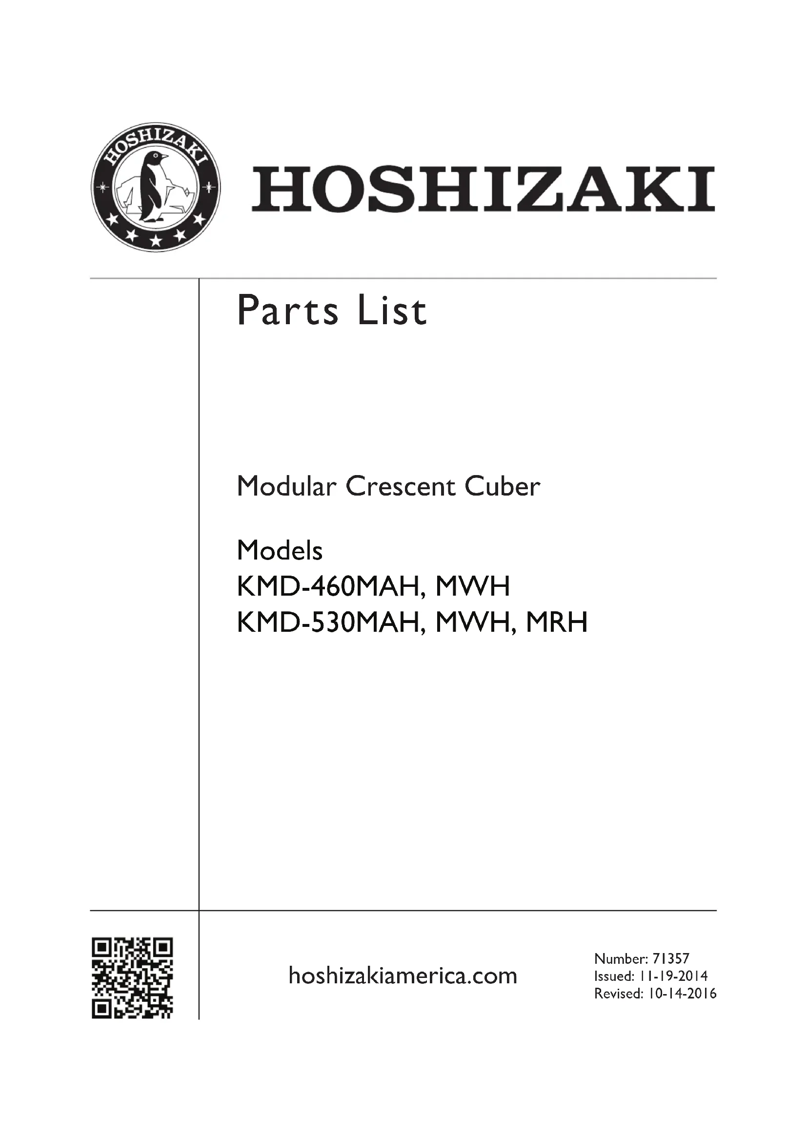
A. Main Assembly & Refrigeration Circuit KMD-460MAH, KMD-530MAH
D-0 to F-1
text_image
Exploded view diagram of a server rack system with numbered components for identification| Title: A. Main Assembly & Refrigeration Circuit Model: KMD-460MAH, KMD-530MAH | |||||||||||
| Index No. | Description | Material or Model Number Part Number | Required Number | ||||||||
| D-0 to F-1 | |||||||||||
| Main Assembly | |||||||||||
| 1 Front Panel 3A5196G01 1 | |||||||||||
| 2 Basket 4A0808L03 1 | |||||||||||
| 3 Top Panel 3A4373G01 1 | |||||||||||
| 4 Right Side Panel 2A4137G01 1 | |||||||||||
| 5 Louver 1A1329-01 1 | |||||||||||
| 6 Air Filter | 2A4128G01 2 | ||||||||||
| 7 Front Insulation A | 3A5570G01 1 | ||||||||||
| 8 Front Insulation B | 3A4386G01 1 | ||||||||||
| 9 Top Insulation | 3A4394G01 1 | ||||||||||
| 10 Control Box Cover | 3A8289-01 | 1 | |||||||||
| 11 Bin Control | 2A4393G01 1 | ||||||||||
| 12 Bin Control Bracket | 3A8283-01 | 1 | |||||||||
| Refrigeration Circuit | |||||||||||
| 13 | Compressor | KMD-460MAH | 4A4479-01 | 1 | |||||||
| KMD-530MAH 4 | 4A4376-01 1 | ||||||||||
| 14 | Condenser | 1A1363-01 1 | |||||||||
| 15 | Evaporator | KMD-460MAH | 2A4144G01 | 1 | |||||||
| KMD-530MAH 2 | 4A7811G01 1 | ||||||||||
| 16 | Thermostatic Expansion Valve | 4A1414-01 | 1 | ||||||||
| 17 | Thermostatic Expansion Valve Cover | 3A0944-01 | 1 | ||||||||
| 18 | Thermostatic Expansion Valve Bulb Holder | 3A0107-01 | 1 | ||||||||
| 19 | Hot Gas Valve Body | 4A3978-01 | 1 | ||||||||
| 20 | Valve Coil 4A3277-01 1 | ||||||||||
| 21 | Strainer | 441569-02 | 1 | ||||||||
| 22 | High-Pressure Switch | 463180-04 | 1 | ||||||||
| 23 | Thermistor | 429006-03 1 | |||||||||
| 24 | Thermistor Holder | 427430-01 | 1 | ||||||||
| 25 | Fan Motor (includes blade) | P02596-01 | 1 | ||||||||
| 26 | Drier | 4A1113-01 | 1 | ||||||||
| 27 | Heat Exchanger | KMD-460MAH 2 | 4A5259G01 1 | ||||||||
| KMD-530MAH 1 | 4A3477G01 1 | ||||||||||
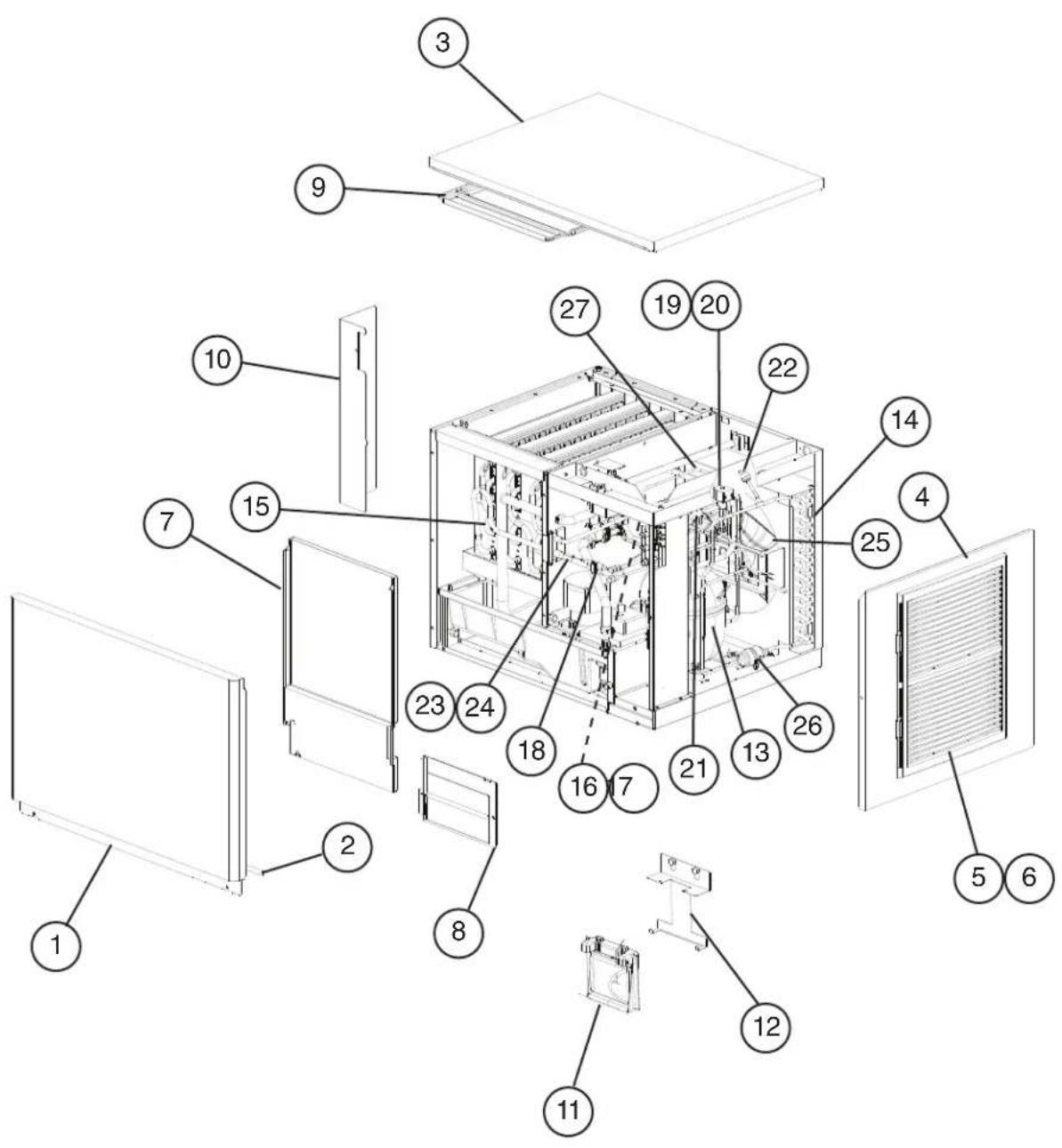
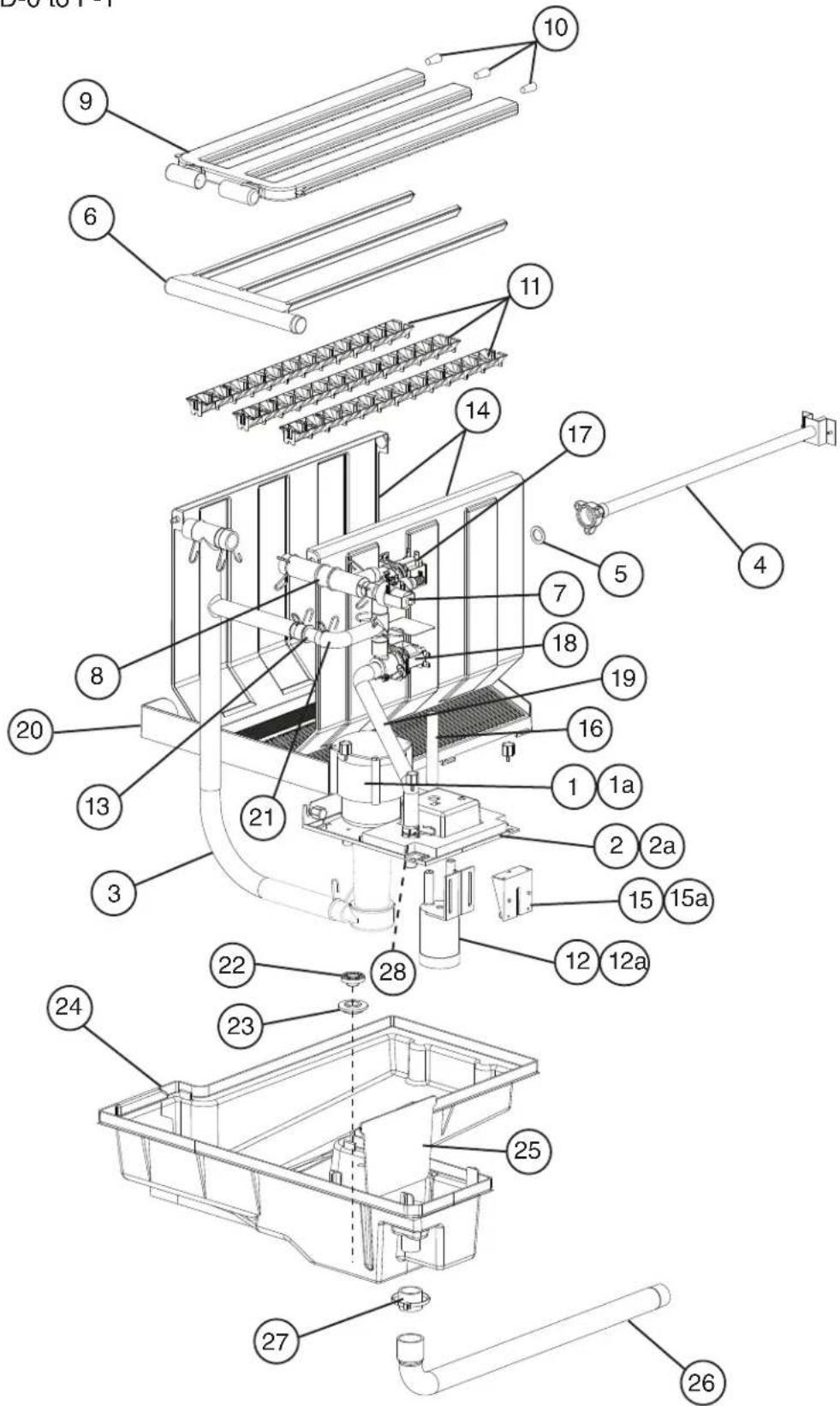
A. Main Assembly & Refrigeration Circuit KMD-460MWH, KMD-530MWH
D-0 to F-1
text_image
Exploded view diagram of a server rack system with numbered components for identification| Title: A. Main Assembly & Refrigeration Circuit Model: KMD-460MWH, KMD-530MWH | |||||||||||
| Index No. Description | Material or Model Number Part Number | Required Number | |||||||||
| D-0 to F-1 | |||||||||||
| Main Assembly | |||||||||||
| 1 Front Panel 3A5196G01 1 | |||||||||||
| 2 Basket 4A0808L03 1 | |||||||||||
| 3 Top Panel 3A4373G01 1 | |||||||||||
| 4 Right Side Panel 2A4173G01 1 | |||||||||||
| 5 Front Insulation A 3A5570G01 1 | |||||||||||
| 6 Front Insulation B 4A4283-01 1 | |||||||||||
| 7 Top Insulation | 3A4394G01 1 | ||||||||||
| 8 Control Box Cover | 3A8289-01 1 | ||||||||||
| 9 Bin Control | 2A4393G01 1 | ||||||||||
| 10 | Bin Control Bracket | 3A8283-01 | 1 | ||||||||
| Refrigeration Circuit | |||||||||||
| 11 | Compressor | KMD-460MWH | 4A4479-01 | 1 | |||||||
| KMD-530MWH | 4A4376-01 | 1 | |||||||||
| 12 | Condenser | 3A8514-01 | 1 | ||||||||
| 13 | Water Regulating Valve | 4A0911-06 | 1 | ||||||||
| 14 | Male Connector | 4A1087-01 | 1 | ||||||||
| 15 | Evaporator | KMD-460MWH | 2A4144G01 | 1 | |||||||
| KMD-530MWH | 2A7811G01 1 | ||||||||||
| 16 | Thermostatic Expansion Valve | 4A1414-01 | 1 | ||||||||
| 17 | Thermostatic Expansion Valve Cover | 3A0944-01 | 1 | ||||||||
| 18 | Thermostatic Expansion Valve Bulb Holder | 3A0107-01 | 1 | ||||||||
| 19 | Hot Gas Valve Body | 4A3978-01 | 1 | ||||||||
| 20 | Valve Coil 4A3277-01 1 | ||||||||||
| 21 | Strainer | 441569-02 | 1 | ||||||||
| 22 | High-Pressure Switch | 463180-05 | 1 | ||||||||
| 23 | Thermistor | 429006-03 | 1 | ||||||||
| 24 | Thermistor Holder | 427430-01 | 1 | ||||||||
| 25 | Drier | 4A1113-01 | 1 | ||||||||
| 26 | Heat Exchanger | KMD-460MWH | 2A5259G01 | 1 | |||||||
| KMD-530MWH | 1A3477G01 1 | ||||||||||
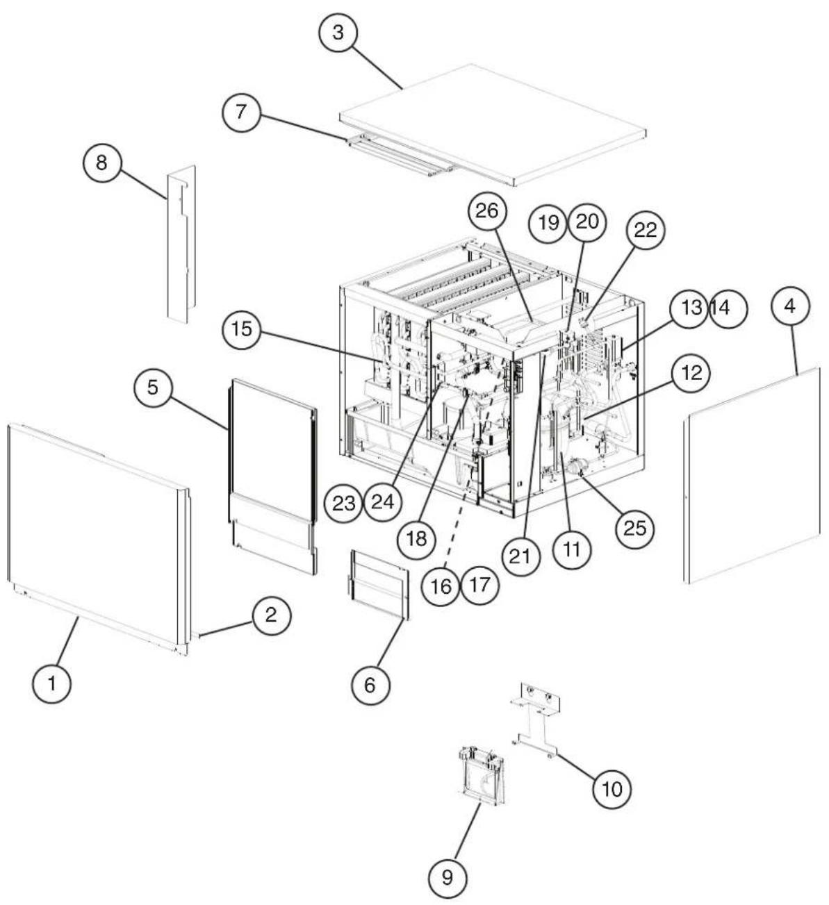
A. Main Assembly & Refrigeration Circuit KMD-530MRH
D-0 to F-1
text_image
Exploded view diagram of a server rack system with numbered components for identification| Title: A. Main Assembly & Refrigeration Circuit Model: KMD-530MRH | |||||||||||
| Index No. Description | Material or Model Number | Part Number | Required Number | ||||||||
| D-0 to F-1 | |||||||||||
| Main Assembly | |||||||||||
| 1 Front Panel 3A5196G01 1 | |||||||||||
| 2 Gasket 4A0808L03 | |||||||||||
| 3 Top Panel 3A4373G01 1 | |||||||||||
| 4 Right Side Panel 2A4173G01 1 | |||||||||||
| 5 Front Insulation A 3A5570G01 1 | |||||||||||
| 6 Front Insulation B 3A4386G01 1 | |||||||||||
| 7 Top Insulation 3A4394G01 1 | |||||||||||
| 8 Control Box Cover | 3A8289-01 1 | ||||||||||
| 9 Junction Box Cover | 43B410-01 1 | ||||||||||
| 10 Bin Control Bracket | 3A8283-01 | 1 | |||||||||
| 11 Bin Control | 2A4393G01 1 | ||||||||||
| Refrigeration Circuit | |||||||||||
| 12 | Compressor | 4A4376-01 | 1 | ||||||||
| 13 | Receiver | 437596-01 | 1 | ||||||||
| 14 | Crankcase Heater | 4A5091-01 | 1 | ||||||||
| 15 | Evaporator | 2A7811G01 1 | |||||||||
| 16 | Thermostatic Expansion Valve | 4A1414-01 | 1 | ||||||||
| 17 | Thermostatic Expansion Valve Cover | 3A0944-01 | 1 | ||||||||
| 18 | Thermostatic Expansion Valve Bulb Holder | 3A0107-01 | 1 | ||||||||
| 19 | Hot Gas Valve Body | 4A3978-01 | 1 | ||||||||
| 20 | Liquid Line Valve Body | 4A3276-01 | 1 | ||||||||
| 21 | Valve Coil 4A3277-01 2 | ||||||||||
| 22 | Strainer | 441569-02 | 1 | ||||||||
| 23 | High-Pressure Switch | 463180-04 | 1 | ||||||||
| 24 | Thermistor | 429006-03 | 1 | ||||||||
| 25 | Thermistor Holder | 427430-01 | 1 | ||||||||
| 26 | Drier | 4A2663-01 | 1 | ||||||||
| 27 | Discharge Line Coupling | 434072-01 | 1 | ||||||||
| 28 | Liquid Line Coupling | 426554-01 | 1 | ||||||||
| 29 | Heat Exchanger | 1A3477G01 1 | |||||||||
B. Water Circuit
KMD-460M_H, KMD-530M_H
D-0 to F-1
text_image
Exploded view diagram of a mechanical device with numbered components for identification| Title: B. Water Circuit Model: KMD-460M_H, KMD-530M_H | |||||||||||
| Index No. Description | Material or Model Number | Part Number | Required Number | ||||||||
| D-0 to F-1 | |||||||||||
| 1 Pump Motor 4A4259-01 1 | |||||||||||
| 1a Thumbscrew 415949G12 1 | |||||||||||
| 2 Pump Motor Bracket 4A4251G01 1 | |||||||||||
| 2a Thumbscrew 415949G12 2 | |||||||||||
| 3 Pump Hose 4A5685-01 1 | |||||||||||
| 4 Water Supply Pipe 4A4250G01 1 | |||||||||||
| 5 Rubber Gasket 413854-03 1 | |||||||||||
| 6 | Water Supply Tube | 2A4132-01 | 1 | ||||||||
| 7 Inlet Water Valve | KMD-460MAH KMD-460MWH | 3U0111-03 | 1 | ||||||||
| KMD-530MAH KMD-530MRH | 4A5251-07 | 1 | |||||||||
| KMD-530MWH | 4A5251-03 | 1 | |||||||||
| 8 Water Valve Hose (tee) | 3A | 4366-01 1 | |||||||||
| 9 | Spray Tube | 2A4133-01 | 1 | ||||||||
| 10 | Plug | 4A0176-01 | 3 | ||||||||
| 11 Spray Guide | 2A | 4282-04 3 | |||||||||
| 12 | Float Switch 4A3624-01 1 | ||||||||||
| 12a T2 Screw | 7P32-0412 | 2 | |||||||||
| 13 | Evaporator Pipe | 4A3765-02 | 1 | ||||||||
| 14 | Splash Curtain | KMD-460MAH KMD-460MWH | 3A4387G01 2 | ||||||||
| KMD-530MAH KMD-530MRH KMD-530MWH | 2A7452G01 2 | ||||||||||
| 15 | Float Switch Bracket | 327757-01 | 1 | ||||||||
| 15a | T2 Screw | 4x12 | 7P32-0412 | 1 | |||||||
| 16 | Vinyl Hose | 40 mm | 7716-1216 | 1 | |||||||
| 17 | Wash Valve | KMD-460MAH KMD-460MWH | 4A5745-01 | 1 | |||||||
| KMD-530MAH KMD-530MWH KMD-530MRH | 4A5530-01 1 | ||||||||||
| 18 | Drain Valve | KMD-460MAH KMD-460MWH | 4A5745-03 | 1 | |||||||
| KMD-530MAH KMD-530MWH KMD-530MRH | 4A5530-03 | 1 | |||||||||
| 19 | Drain Hose | 4A5688-01 | 1 | ||||||||
| 20 Cube Guide | 1A | 1336-01 | |||||||||
| 21 Bypass Hose (tee) 4A5687-01 | 1 | ||||||||||
| 22 Drain Plug | 30 | 9246-01 | |||||||||
| 23 | O-Ring | 7611-P015 | 1 | ||||||||
| 24 Tank | 3A | 8316G01 | |||||||||
| 25 Tank Separator | 4A | 4239-01 1 | |||||||||
| 26 Tank Drain Hose | 4A | 5684-01 1 | |||||||||
| 27 | Vinyl Hose | 25 mm | 4A0658L01 | 1 | |||||||
| 28 Vinyl Hose | 77 | 16-1519 | |||||||||
| Hose Clamp | |||||||||||
| Hose Clamp | 18 mm, SS | 427443-05 | 2 | ||||||||
| Hose Clamp | 25 mm, SS | 427443-03 | 4 | ||||||||
| Hose Clamp | 20 mm, SS | 427443-06 | 6 | ||||||||
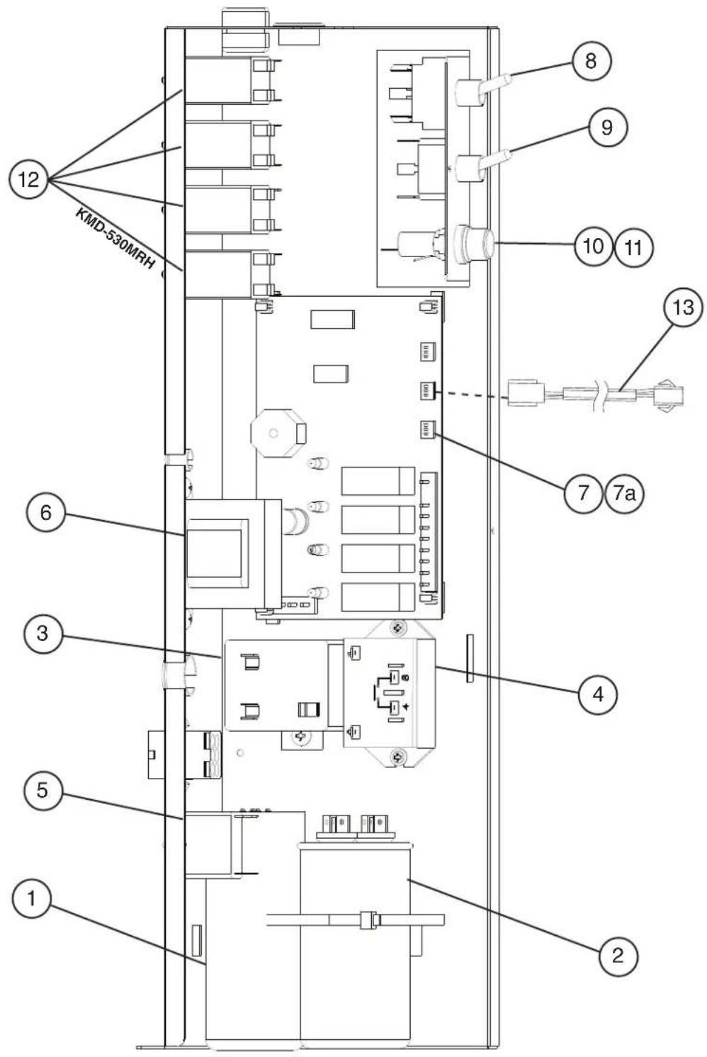
C. Control Box Assembly KMD-460M\_H, KMD-530M\_H D-0 to F-1
text_image
12 KMD-530MRH 6 3 5 1 2 4 7 7a 8 9 10 11 13| Title: C. Control Box Assembly Model: KMD-460M_H, KMD-530M_H | |||||||||||
| Index No. Description | Material or Model Number Part Number | Required Number | |||||||||
| D-0 to F-1 | |||||||||||
| 1 Start Capacitor 243-292MFD, | 165VAC | 3A0076-20 1 | |||||||||
| 2 Run Capacitor 35MFD, | 440VAC | 3A2005-12 1 | |||||||||
| 3 Start Relay 4A1107-11 1 | |||||||||||
| 4 Compressor Relay 4A3140-01 1 | |||||||||||
| 5 Pump Motor Capacitor KMD-460MAH | KMD-530MAH 6MFD, 220VAC | 4A2128-08 1 | |||||||||
| KMD-460MWH KMD-530MWH KMD-530MRH 2.5MFD, 250VAC | 4A2128-05 1 | ||||||||||
| 6 Control Transformer 3A0172-01 | 1 | ||||||||||
| 7 "G" Control Board | 2A3792-01 1 | ||||||||||
| 7a | Control Board Support | 4A0336-03 | 4 | ||||||||
| 8 Toggle Switch (Control) | 4A3119-01 1 | ||||||||||
| 9 Toggle Switch (Service) | 4A0985-01 1 | ||||||||||
| 10 | Fuse Holder | 4A5443-01 | 1 | ||||||||
| 11 | Fuse | AGC-10, 250VAC | 4A0893-07 | 1 | |||||||
| 12 | Relay (X10, X11, X12, X13) | KMD-460MAH KMD-460MWH KMD-530MAH KMD-530MWH | 406132-07 | 3 | |||||||
| KMD-530MRH | 4 | ||||||||||
| 13 | Mechanical Bin Control Wire Harness | 4A2200G04 | 1 | ||||||||
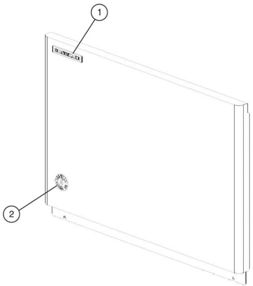
D. Accessories & Labels KMD-460\_H, KMD-530M\_H D-0 to F-1
text_image
Technical diagram of a rectangular panel with labeled components, showing two numbered parts and a central circular feature.| Title: D. Accessories & Labels Model: KMD-460M_H, KMD-530M_H | |||||||||||
| IndexNo. | Description | Material orModel Number | Part Number | Required Number | |||||||
| D-0toF-1 | |||||||||||
| 1 Hoshizaki Emblem Label 4A0560-01 1 | |||||||||||
| 2 Penguin Label 4A0526-01 1 | |||||||||||
| 3 Universal Brace 4A0363-01 2 | |||||||||||
| 3a Hex Bolt 5x12 7B02-0512 2 | |||||||||||