GX680III - Appareil photo FUJI - Notice d'utilisation et mode d'emploi gratuit
Retrouvez gratuitement la notice de l'appareil GX680III FUJI au format PDF.
| Type de produit | Appareil photo moyen format reflex mono-objectif à obturateur central |
| Marque | Fuji |
| Modèle | GX680III |
| Format de film | 6×8 cm (56×76 mm) avec possibilité de formats 6×7, 6×6 et 6×4,5 cm via masques interchangeables |
| Type de film | Film en rouleau 120 (9, 10, 12 ou 16 poses selon le format) et 220 (double) |
| Objectif standard | EBC Fujinon GX M 135mm f/5.6 (monture interchangeable) |
| Obturateur | Central électronique, vitesses B, 8s à 1/400s, synchro flash X sur toutes les vitesses |
| Viseur | Reflex au niveau de la taille, capuche pliable, grossissement 2,5× (-1 dioptrie), verre de visée interchangeable |
| Alimentation | 3 piles lithium CR123A/DL123A (3V) pour le boîtier ; 2 piles CR2/DLCR2 (3V) pour le porte-film III N |
| Dimensions (boîtier nu) | 188 (L) × 222 (P) × 213 (H) mm |
| Poids (boîtier nu) | 2690 g (sans piles) |
| Poids (avec objectif 135mm et porte-film) | 4070 g (sans piles) |
| Fonctions principales | Moteur intégré pour avancement automatique du film, système à code-barres pour réglage ISO automatique, impression de données en dehors du cadre, mouvements du bloc avant (bascules, décentrements, rotations), modes de prise de vue (simple, continu, multi-exposition) |
| Entretien et nettoyage | Essuyer avec un chiffon sec et propre ; ne pas utiliser de solvants ; dépoussiérer avec une brosse et une soufflette ; nettoyer les contacts électriques avec un chiffon sec |
| Sécurité | Ne pas immerger dans l'eau ; en cas de chute dans l'eau, contacter un service agréé ; éviter les températures extrêmes et l'humidité ; utiliser uniquement les piles recommandées |
| Pièces détachées et réparabilité | Pièces disponibles auprès du service après vente Fuji ; confier toute réparation à un technicien qualifié ; faire vérifier l'appareil une fois par an |
| Informations générales | Appareil professionnel conçu pour le studio (portrait, nature morte, publicité) ; compatible avec les accessoires de la gamme GX680 |
FOIRE AUX QUESTIONS - GX680III FUJI
Questions des utilisateurs sur GX680III FUJI
0 question sur cet appareil. Repondez a celles que vous connaissez ou posez la votre.
Poser une nouvelle question sur cet appareil
Téléchargez la notice de votre Appareil photo au format PDF gratuitement ! Retrouvez votre notice GX680III - FUJI et reprennez votre appareil électronique en main. Sur cette page sont publiés tous les documents nécessaires à l'utilisation de votre appareil GX680III de la marque FUJI.
MODE D'EMPLOI GX680III FUJI
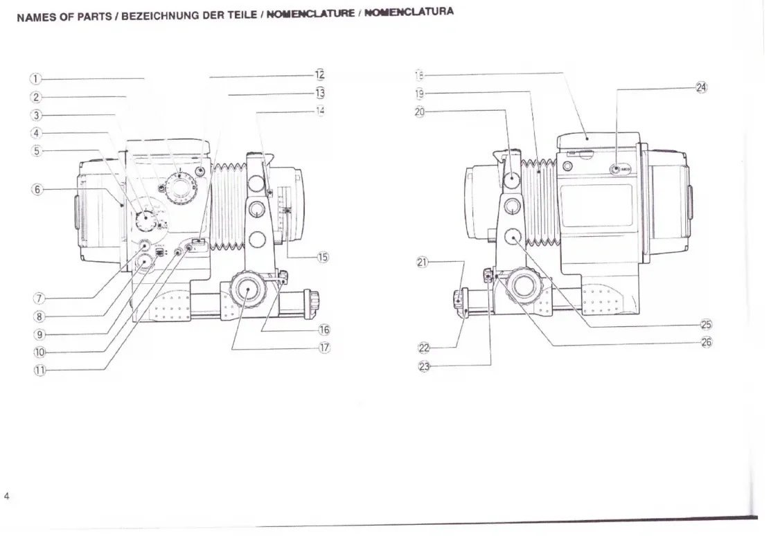
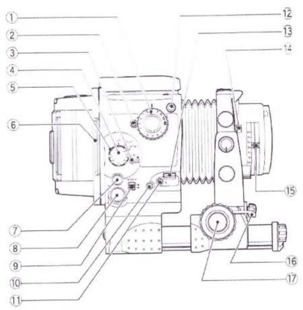
NAMES OF PARTS / BEZEICHNUNG DER TEILE / NOMENCLATURE / NOMENCLATURA
text_image
Technical diagram of a mechanical device with numbered parts for identification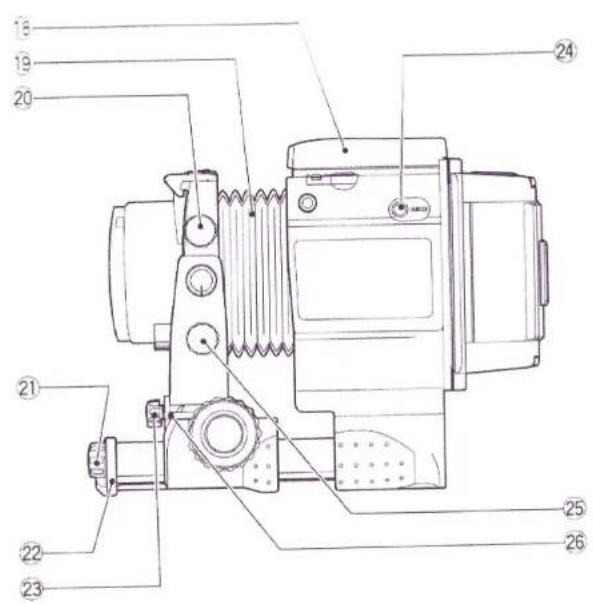
text_image
Technical diagram of a mechanical device with numbered parts for identification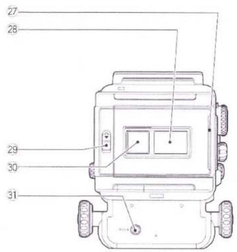
text_image
27 28 29 30 31Camera Body Liquid Crystal Display (LCD)
Kameragehäuse-Flüssigkristallanzeige (LCD)
Affichage à cristaux liquides (LCD) du boîtier de l'appareil
Visualizador de cristal líquido (LCD) de la caja de la cámara
*The diagram shows all crystal displays in the "on" state.
*Zur Erleichterung der Übersicht zeigt die Abbildung alle
Anzeigen im eingeschalteten Zustand.
*Le dessin présente tous éléments de l'affichage à l'état allumé.
*El diagrama muestra todas las visualizaciones del LCD
en el estado "activado".
text_image
Technical diagram of a mechanical device with numbered parts for identificationFilm Holder III N Liquid Crystal Display (LCD)
Flüssigkristallanzeige (LCD) des Filmhalters Typ III N
Affichage à cristaux liquides (LCD) de porte-film III N
Visualizador de cristal líquido (LCD) del portapelícula III N
text_image
52 53 AUTO ISO 8:8.8" No. 6×8 AV/TV 120 6×7 DATE 220 6×6 TIME 6×4.5 54 55 56 57 58 59 60Fig. 1
Fig. 2
Fig. 3
Fig. 4
text_image
A B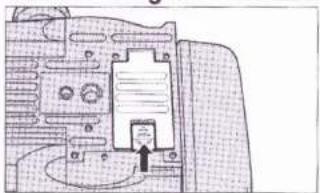
natural_image
Architectural floor plan sketch showing room layouts and structural elements (no text or labels)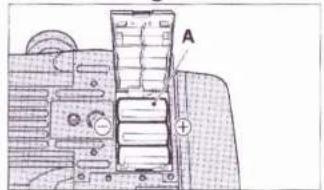
text_image
A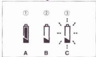
text_image
① A ② B ③ CFig. 7
Fig. 8
Fig. 5
Fig. 6
text_image
A B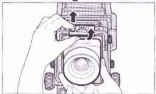
natural_image
Hand holding a mechanical component with arrows indicating assembly or adjustment (no text or symbols visible)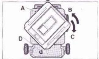
text_image
A B C D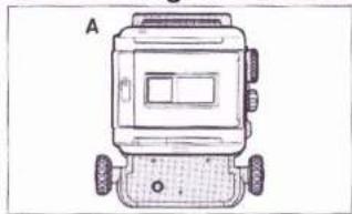
natural_image
Top-down line drawing of a small robotic device with wheels and a screen (no text or symbols)Fig. 11
Fig. 12
Fig. 9
Fig. 10
natural_image
Diagram of a vehicle chassis with labeled components A and B, showing no text or symbols beyond labels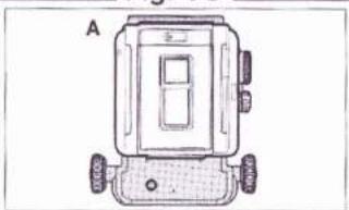
natural_image
Top-down line drawing of a mechanical device with wheels and a central panel (no text or symbols)
natural_image
Technical line drawing of a mechanical device with no visible text or symbols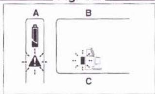
text_image
A B CFig. 15
Fig. 16
Fig. 13
Fig. 14
natural_image
Technical line drawing of a mechanical device with no visible text or symbols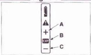
text_image
A + B EXP - C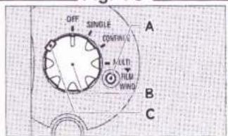
text_image
OFF SINGLE CONTINUING MOLD FLM WIND A B C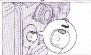
natural_image
Mechanical assembly diagram showing gears and a rotating component (no text or labels)Fig. 17
Fig. 18
Fig. 19
Fig. 20
text_image
Technical diagram of a mechanical device with labeled components and parts, including dials, gauges, and a labeled component A.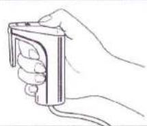
natural_image
Line drawing of a hand holding a small electronic device (no text or symbols)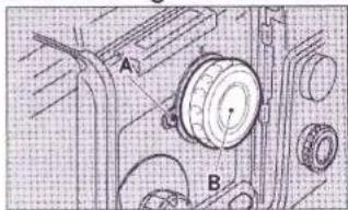
text_image
A B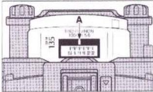
text_image
A 135 Φ100 Φ200 Φ300 Φ400 Φ500 Φ600 Φ700 Φ800 Φ900 Φ1000 Φ1100 Φ1200 Φ1300 Φ1400 Φ1500 Φ1600 Φ1700 Φ1800 Φ1900 Φ2000 Φ2100 Φ2200 Φ2300 Φ2400 Φ2500 Φ2600 Φ2700 Φ2800 Φ2900 Φ3000 Φ3100 Φ3200 Φ3300 Φ3400 Φ3500 Φ3600 Φ3700 Φ3800 Φ3900 Φ4000 Φ4100 Φ4200 Φ4300 Φ4400 Φ4500 Φ4600 Φ4700 Φ4800 Φ4900 Φ5000 Φ5100 Φ5200 Φ5300 Φ5400 Φ5500 Φ5600 Φ5700 Φ5800 Φ5900 Φ6000 Φ6100 Φ6200 Φ6300 Φ6400 Φ6500 Φ6600 Φ6700 Φ6800 Φ6900 Φ7000 Φ7100 Φ7200 Φ7300 Φ7400 Φ7500 Φ7600 Φ7700 Φ7800 Φ7900 Φ8000 Φ8100 Φ8200 Φ8300 Φ8400 Φ8500 Φ8600 Φ8700 Φ8800 Φ8900 Φ9000 Φ9100 Φ9200 Φ9300 Φ9400 Φ9500 Φ9600 Φ9700 Φ9800 Φ9900 Φ1 1 2 3 4 5 6 7 8 9 1 2 3 4 5 6 7 8 9 1 2 3 4 5 6 7 8 9 1 2 3 4 5 6 7 8 9 1 2 3 4 5 6 7 8 9 1 2 3 4 5 6 7 8 9 1 2 3 4 4 5 6 7 8 9 1 2 3 4 4 5 6 7 8 9 1 2 3 4 4 5 6 7 8 9 1 2 3 4 4 5 6 7 8 9 1 2 3 4 4 5 6 7 8 9 1 2 3 5Fig. 23
Fig. 24
Fig. 21
Fig. 22
text_image
A B C D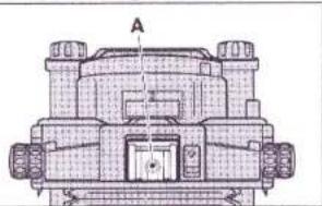
natural_image
Technical line drawing of a mechanical component with labeled section A (no text or symbols beyond label)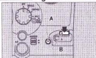
text_image
A B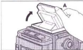
natural_image
Diagram of a hand holding a device with an arrow indicating rotation (no text or symbols present)Fig. 27
Fig. 28
Fig. 25
Fig. 26
text_image
Technical diagram of a mechanical device with labeled components A through O, showing directional arrows and component positioning.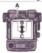
natural_image
Technical line drawing of a mechanical device with no visible text or symbols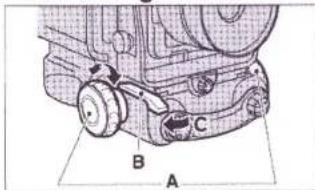
text_image
Technical diagram of a mechanical assembly with labeled parts A, B, and CFig. 31
Fig. 32
Fig. 29
Fig. 30
natural_image
Technical line drawing of a mechanical component with no visible text or symbols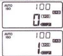
text_image
AUTO ISO 100 6*8 120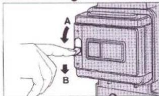
text_image
Diagram showing a hand pressing a button labeled A and B to interact with a device, likely illustrating a manual or mechanical process.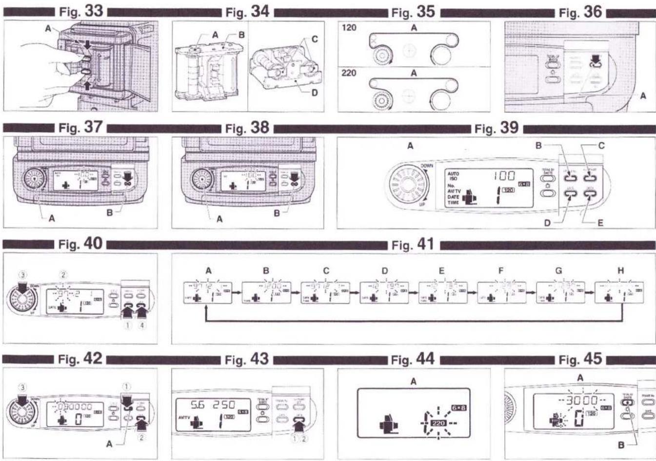
Fig. 46
Fig. 47
Fig. 48
Fig. 49
natural_image
Hand placing a component into a circular housing (no text or symbols visible)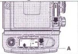
natural_image
Technical line drawing of a mechanical device with labeled components (no readable text or symbols)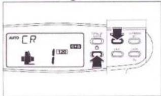
text_image
AUTO CR 120 0.05 0.05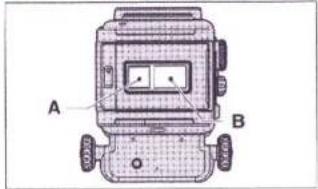
text_image
A BFig. 52
Fig. 53
Fig. 50
Fig. 51
natural_image
Technical line drawing of a mechanical device with no visible text or symbols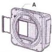
natural_image
Hand inserting a component into a device (no text or symbols visible)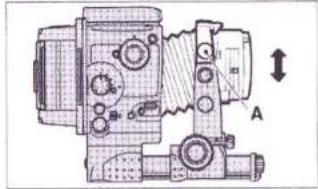
natural_image
Technical line drawing of a mechanical device with no visible text or symbolsFig. 56
Fig. 57
Fig. 54
Fig. 55
text_image
A B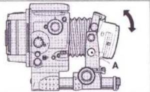
natural_image
Technical line drawing of a mechanical device with no visible text or symbols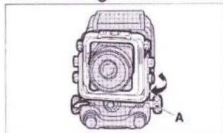
natural_image
Technical line drawing of a mechanical component with labeled section A (no text or symbols beyond label)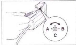
text_image
A • ⊕ B CFig. 60
Fig. 61
Fig. 58
Fig. 59
text_image
A B C MIF BOX↑ ↓ 光 C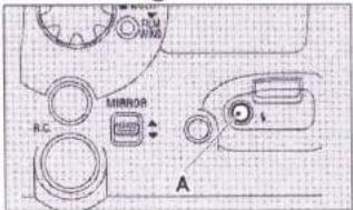
text_image
R.C MIRROR A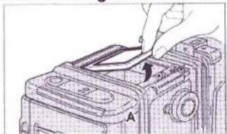
natural_image
Line drawing of a hand inserting a component into a device (no text or symbols)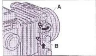
text_image
A B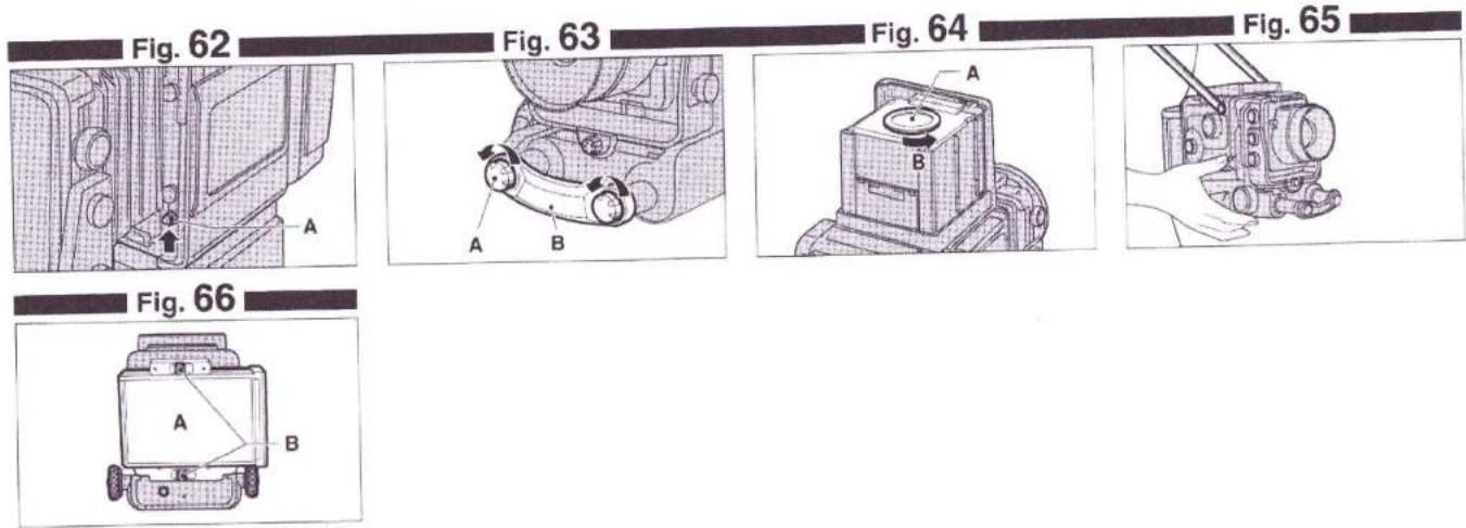
text_image
Fig. 62 Fig. 63 Fig. 64 Fig. 65 A A B A B Fig. 66 A BCONTENTS
NAMES OF PARTS 11
SPECIAL FEATURES 12
CAMERA PARTS AND THEIR FUNCTIONS 13
I. GETTING READY TO TAKE PICTURES 15
-
Mounting the camera on a tripod or camera stand—15
-
Power source 15
-
Mounting and dismounting the lens 16
-
Mounting and dismounting the film holder III N and revolving it—16
II. LCD INFORMATION PANEL 16
-
Stand-by monitor 16
-
Incorrect-exposure warning monitor 17
III.BASIC PROCEDURES 18
-
Setting the mode switch 18
-
Using the shutter release 18
-
Using the remote-control shutter release III 18
-
Setting the shutter speed selector 18
-
Setting the aperture selector 18
-
Taking flash pictures 18
-
Using the finder hood 19
-
Framing your picture 19
-
Focusing the lens 19
IV. USING THE FILM HOLDER ⅢN 20
-
Loading batteries 20
-
Film holder III N's liquid crystal display (LCD) ———— 20
-
Opening and closing the camera back 20
-
Inserting and extracting the film holder's inner frame — 20
-
Loading the take-up spool and film 20
-
Positioning the film start mark 20
-
Automatic first-frame setting 21
-
Setting film speed (ISO) 21
-
Printing data outside picture frame 21
-
Erroneous inner frame use warning
(When bar code films are used) 22
-
How to read total number of shots 22
-
Changing format masks 22
-
LCD back light illumination 23
-
Film type indication 23
-
Using the memo space and film reminder slot 23
-
Sliding in, sliding out, and putting away the dark slide — 23
-
Winding and unloading the film 23
V. CAMERA MOVEMENTS 23
-
Rise and fall 23
-
Shifts 24
-
Tilts 24
-
Swings 24
VI. OTHER PROCEDURES 24
- Adjusting the sound level of the
incorrect-exposure warning buzzer 24
-
Shooting with the mirror up 24
-
Using sync test button 24
-
Changing the focusing screen 25
-
Changing the bellows 25
-
Using the extension rails (For taking close-ups) 25
-
Changing the finder hood's magnifying glass 25
-
Taking hand-held shots 25
-
Taking pictures with instant films 25
-
Using large size lenses 25
CAMERA CARE 26
SPECIFICATIONS 26
NAMES OF PARTS
① Shutter Speed Selector
② AE Mode Lock
③ FILM WIND Button
④ Mode Switch
⑤ Mode Switch Lock Lever
⑥ Dark Slide
⑦ Communication Connector
⑧ Remote-control Shutter Release Socket
⑨ MIRROR Up/Down Switch
⑩ Sync Socket
⑪ Sync Test Button
⑫ Strap eyelet
⑬ Shutter Release
⑭ Stop-down Lever
⑮ Aperture Selector
⑯ Focus Lock Lever
⑰ Focusing Knobs
⑱ Collapsible Finder Hood
19 Bellows
20 Rise/Fall Knobs
②1 Front Bar Lock Screw
② Front Bar
②3 Shift Knob
⑳ Side Cover Lock Release Button
25 Tilt Knobs
②6 Swing Lever
② Dark Slide Pocket
⑳ Memo Space
29 Camera Back Lock
③0 Film Reminder Slot
③1 Revolving Lock
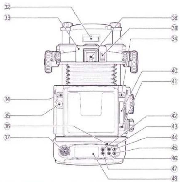
③2 Aperture Indicator Window
③ Lens Lock
③4 Finder Lock Release Buttons (in two places)
35 Spirit Level
③6 Mode Button Cover
③7 Up/Down Dial
38 Hotshoe
39 Lens Lock Release
④0 Camera Body Liquid Crystal Display (LCD)
④ Call/Light Button for the LCD on Camera
④2 Total Shots Indicator Button
④3 FRAME Number Button
④4 1st FRAME SET Button
④5 DATA/ISO Button
④6 DATE Button
④7 Call/Light Button for the LCD on Film Holder III N
④8 Film Holder III N Liquid Crystal Display (LCD)
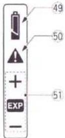
④9 Battery Checker
50 Stand-by Monitor
⑤ Incorrect-exposure Warning Monitor
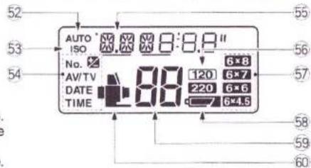
⑤2 Automatic Film Speed Setting
53 Film Speed
⑤4 Print Sign
55 AV/TV/Year-Month-Day/Hour/Number of Total Shots/ISO/Frame No. (Serial No.)
⑤6 Type of Film
57 Picture Size (when mask inserted)
58 Battery Checker
59 Exposure Counter
60 Camera Monitor
SPECIAL FEATURES
The GX680 III Professional is designed primarily for taking studio photographs which constitute the bulk of the work done by professional photographers, and studio work consists mainly of portrait, still life, and merchandise photography that invariably demands extremely subtle lighting and sophisticated photographic techniques.
Equipped to meet the most critical professional requirements and built for ease of use to enable the user to concentrate heart and soul on his subject, it is truly a "professional camera for the pros". The professional photographer who holds the GX680 III in his hands is sure to be inspired by a new creative urge.
1. Employment of multi-formats for pros
Based on the 6×8cm (the actual picture size is 56×76mm) format which is ideal for subject framing and which provides print cropping and press trimming with a high trimming efficiency, you can select 6×7cm, 6×6cm and 6×4.5cm formats freely by replacing aperture masks. Further the built-in revolving back lets you freely use the frames either vertically or horizontally.
2. Motor-drive SLR system lets you concentrate on your subject
Built for the pro and with emphasis on ease of use, its motor drive for rapid-sequence shooting, electronically controlled interlens shutter, and SLR focusing system free you from mechanical distractions and let you concentrate heart and soul on your subject.
3. Built-in revolutionary professional features
● Special film holder III N which allows the film to be set to the first frame automatically without mounting the film holder on the camera
● Year/month/day, hour/minute, photographing data and frame number can be printed in the outside picture frame.
● Function to display total number of shots individually on the lens, camera body, and film holder III N
● Fully automatic film transport - there is no precise film start-mark setting to do.
- Incorrect-exposure warning monitor warns you against incorrect exposure, non-exposure, and faulty flash synchronization.
- Sync test button lets you test flash discharge and sync-cord synchronization.
- Last-frame warning buzzer alerts you as soon as the last frame moves into shooting position.
● Stand-by monitor tells you at a glance that all is ready for shooting.
● Camera illustration display tells you at a glance which part of the camera is faulty.
4. Camera-front movements permit the use of sophisticated photographic techniques
The camera front can be moved to control image sharpness and to change the shape and position of objects in the picture. The electronic shutter control and group of interchangeable lenses with a large image circle allow various camera movements. This is the first SLR camera with a pro-specifications realizing the special feature.
5. A full-fledged professional system camera
A group of lenses, a variety of film holders, a remote-control shutter release III and various other accessories for expanding the camera's picture-taking scope, which were developed after thorough researches into professional needs, are available to the user.
6. Use of a bar code system film
With a bar code system film used, erroneous film setting and controls are perfectly prevented.
● Automatic film speed (ISO) setting
● Erroneous 120/220 use warning
● Automatic data printing density setting by each reversal negative film and monographic film
■ What is a "Bar Code System"?
The film speed (ISO), type of the film (120/220), and other data are recorded in a bar code format on the seal which connects the leader paper with the film. The Fujifilm's bar code system allows the camera reading this bar code and setting the film speed and type of the film automatically.
■ Easy-loading film

natural_image
Simple line drawing of a measuring tool and a plastic container (no text or symbols)Easy-loading film
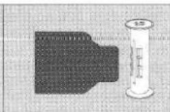
natural_image
Illustration of a pen and a graduated cylinder on a textured surface (no text or symbols)Conventional film
This system allows the film to be easily and correctly loaded simply by inserting the leader paper into the slot on the take-up spool. To be more specific, the round opening in the leader paper head is hooked to the claw on the slot of the take-up spool. The leader paper is properly stretched preventing the roll from slackening and the film is loaded completely.
* GX680 III S is not equipped with camera movement functions.
CAMERA PARTS AND THEIR FUNCTIONS
① Shutter Speed Selector
It can be set to B, 8 to 1/400-second, and A (AE). The AE mode is operative only when the AE finder III is mounted.
② AE Mode Lock
For locking the camera in (and releasing it from) the AE mode.
③ FILM WIND Button
For advancing the film to the next frame after taking multiple-exposure shots with the camera set to the MULTI mode.
④ Mode Switch
For switching the camera off, as well as for setting it to the SINGLE, CONTINUE, and MULTI modes.
⑤ Mode Switch Lock Lever
For setting and releasing the MULTI mode.
⑥ Dark Slide
The film holder can be changed only after the sliding cover has been inserted. To prevent exposing the film inadvertently to light, the sliding cover is made to interlock with a safety device when the film holder is dismounted so that it cannot be pulled out. To simplify inserting the sliding cover, the cover-slot inlet is provided with a white mark and a guide.
⑧ Remote-control Shutter Release Socket
For connecting the camera's special remote-control shutter release III.
⑨ MIRROR Up/Down Switch
For switching the mirror up and down.
⑩ Sync Socket
Since the sync socket is located on the camera body, the lens can be changed with the sync cord connected in spite of the fact that the camera is an interlens-shutter camera.
⑪ Sync Test Button
For testing the flash without using the shutter release. It can be used for measuring the flash exposure range from camera position, as well as for checking sync cord severance and faulty cord connection.
⑫ Strap eyelet
For installing the strap
⑬ Shutter Release
It is operated by pressing it down with the right thumb so that the camera can be kept still even when taking hand-held shots.
⑭ Stop-down Lever
It lets you preview the depth of field of your picture through the viewfinder easily.
⑮ Aperture Selector
It is located on the lens right side to prevent moving it inadvertently and is provided with click stops at each step.
⑯ Focus Lock Lever
It keeps the lens fixed in precise focus.
⑰ Focusing Knobs
Two large knobs, one on each side of the camera, let you focus the lens easily.
⑱ Collapsible Finder Hood
It springs up and folds down with a finger's touch.
19 Bellows
You can change the bellows to suit the situation - to wide-angle bellows if you are using camera-front movements, and to long bellows if you are taking close-ups.
⑳ Rise/Fall Knobs
To use the rise or fall movement to change the position of the objects in your picture, loosen these knobs.
②3 Shift Knob
To shift the camera front laterally to the left or right to change the position of the objects in your picture, loosen this knob.
⑳ Side Cover Lock Release Button
When using the Battery Holder III, the side cover must be detached. This button releases the lock.
25 Tilt Knobs
To tilt the camera front upward or downward to adjust top-to-bottom sharpness, loosen these knobs.
26 Swing Lever
To swing the camera front to the right or left to adjust right-to-left sharpness, push this lever down.
27 Dark Slide Pocket
When taking pictures, pull out and insert the sliding cover in this pocket
so that you won't misplace or lose it.
28 Memo Space
You can jot down exposure notes in this space with a pencil and erase them with a rubber eraser.
29 Camera Back Lock
To open the camera back, lift up the lock and push it down. This two-step action is designed to prevent accidental opening of the camera back.
③0 Film Reminder Slot
Tear off the film-box top and insert it in this slot so that you won't forget which film you are using.
③1 Revolving Lock
To dismount or revolve the film holder III N, release this lock by pushing it in.
32 Aperture Indicator Window
The aperture you have selected will appear in this acrylic-resin window.
33 Lens Lock
It locks the mounted lens securely in place.
34 Finder Lock Release Buttons (in two places)
To dismount the finder, push in these buttons.
35 Spirit Level
It lets you keep the camera level on a tripod or camera stand.
37 Up/Down Dial
For setting the film speed (ISO), the date and time, and frame number. For the film speed, the setting is from ISO 25 up to 3200 in every 1/3 step.
38 Hotshoe
Located in the center of the lens mountings, it moves in unison with the lens' optical axis during camera-front movements.
⑲ Lens Lock Release
To activate the lens lock, the lens lock release must first be pushed in. This two-step action is used to prevent disengaging the lens inadvertently.
④1 Call/Light Button for the LCD on Camera
Pressing in this button will light up part of the LCD.
④2 Total Shots Indicator Button
By counting number of shots on the camera body, lens and each film holder III N, it shows on an LCD the aggregate number of shots in units of 100. You will be able to know whether the camera needs overhauling or periodical maintenance.
FRAME Number Button
Pressing in this button will allow you to check the frame number and to set frame number printing in the outside picture frame. The frame number is set by pressing in this button and by turning the up/down dial.
1st FRAME SET Button
With the film holder III N alone, pressing in this button will cause the film to be set to the first frame automatically.
45 DATA/ISO Button
Pressing in this button will allow you to check the film speed (ISO) and to set data printing in the outside picture frame. The film speed (ISO) is set by pressing in this button and by turning the up/down dial.
46 DATE Button
Pressing in this button will set year/month/day/hour/minute printings in the outside picture frame. The year/month/day/hour/minute correction is made by pressing in this button and by turning the up/down dial.
④7 Call/Light Button for the LCD on Film Holder Ⅲ N
Pressing in this button will light up part of the LCD so that you can watch the LCD even in the dark. With the film holder III N alone, the built-in battery lights up the LCD.
48 Film Holder III N Liquid Crystal Display (LCD)
A large-size LCD shows overall conditions of the camera. Also displayed are camera illustration, battery check, each camera setting, and total number of shots taken (cumulative). Further, being interlocked with the stand-by monitor, displays how the camera has been prepared to take pictures, and warns abnormal camera operations by causing the camera illustration to blink.
50 Stand-by Monitor
For battery check, and indications of how the camera has been prepared to take pictures and abnormal camera operations
⑤1 Incorrect-exposure Warning Monitor
It detects the amount of light reflected by the film by means of an internal light sensor. If the exposure setting is within two stops over or under, it will spell out "EXP", and if the exposure setting is more than two stops over or under, it will show a plus (+) or minus(−) sign. It shows aperture and shutter-speed mis-settings immediately after the shot is taken. When shooting with remote-control shutter release Ⅲ, and the exposure setting is more than two stops over or under, it emits an audible electronic warning. (Its coupling range is from EV5 \~ 19, ISO 100.)
I. GETTING READY TO TAKE PICTURES
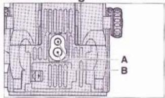
1. MOUNTING THE CAMERA ON A TRIPOD OR CAMERA STAND (Fig. 1)
The camera is provided in the bottom with a 1/4-inch tripod socket and a 3/8-inch tripod socket.
Mount the camera on a tripod or camera stand securely.
1/4-inch Tripod Socket (Fig. 1-A)
3/8-inch Tripod Socket (Fig. 1-B)
* Be sure to use a heavily-built tripod or camera stand that is equipped with a sturdy mounting head.
2. POWER SOURCE
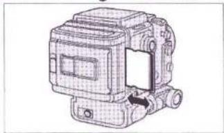
The GX680 III can be used with three CR 123A/DL 123A lithium batteries. (1) Using lithium batteries
First, set the Mode Switch to OFF, and then, push the Battery Compartment Cover Lock toward the arrow to open the Battery Compartment Cover. (Fig. 2)
Insert the batteries in the Battery Compartment with the plus and minus ends set as illustrated on the Battery Compartment, and close the Battery Compartment Cover. (Fig. 3)
CR 123A/DL 123A (3V Lithium) × 3 (Fig. 3-A)
* Change the three batteries at the same time and always use new batteries. Do not mix new and old ones.
■ Check the batteries
Set the Mode Switch to SINGLE. Then, the Stand-by Monitor is actuated.
* The monitor will not be actuated and the camera will not operate unless the batteries are correctly loaded.
■ Check the battery capacity (Fig. 4)
The Stand-by Monitor indications:
① Battery capacity: OK [Lighting (Fig. 4-A)]
② Battery capacity: Insufficient [Lighting (Fig. 4-B)]
Change the batteries with new ones.
③ Battery capacity: Gone [Blinking (Fig. 4-C)]
The shutter lock works.
Change the batteries with new ones.
* Three new batteries will provide power for taking about 3000 shots (as tested according to our battery testing procedure).
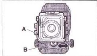
3. MOUNTING AND DISMOUNTING THE LENS
(1) Mounting (Fig. 5)
While pushing the Lens Lock Release toward the arrow, lift up the Lens Lock. The lens Lock will now remain in lifted position. Next, hold the lens with the aperture scale up, hook the lensboard bottom on the lens mounting then press the lens against the lens mounting. The Lens Lock will automatically return to locking position to lock the lens in pace.
Lens Lock Release (Fig. 5-A)
Lens Lock (Fig. 5-B)
* If the lens is not correctly mounted, faulty connection will cause the Stand-by Monitor to blink, so you'll have to remount the lens correctly.
(2) Dismounting (Fig. 6)
While supporting the lens with one hand, push back the Lens Lock Release to the arrow and lift the Lens Lock.
* To prevent dropping the lens, be sure to support it with one hand securely while dismounting it.
* A conventional type interchangeable lens (GX type) can be used. In this case, however, the lens does not work to count total number of shots.
4. MOUNTING AND DISMOUNTING THE FILM HOLDER III N AND REVOLVING IT
(1) Mounting (Fig. 7)
Line up the upper edge of the Film Holder III N with the hyphenated reference line on the Camera Back and, while pressing the Film Holder III N against the Camera Back, turn it toward the arrow so that it locks into horizontal position with a click.
Hyphenated reference line (Fig. 7-A)
Dismounting (Fig. 7-B)
Mounting (Fig. 7-C)
Revolving Lock (Fig. 7-D)
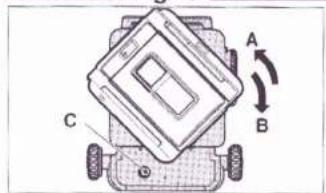
(2) Dismounting (Fig. 8)
First, make sure the Dark Slide is inserted in the Film Holder III N. Next, while pushing the Revolving Lock of the camera body, turn the Film Holder III N 45° to the left and dismount it.
The Film Holder is set horizontally (Fig. 8-A)
(3) Revolving (Fig. 9, 10)
To change the position of the Film Holder from horizontal to vertical, turn it 90^ to the right, and from vertical to horizontal turn it 90^ to the left. (You'll have to press in the Revolving Lock to do it.) It will fall into the correct vertical or horizontal position with a loud click.
Vertical to horizontal (Fig. 9-A)
Horizontal to vertical (Fig. 9-B)
Revolving Lock (Fig. 9-C)
The Film Holder is set vertically (Fig. 10-A)
* Revolving can be done with the Dark Slide removed.
* You'll have to press in the Revolving Lock to mount, dismount, and revolve the Film Holder III N, but once you press it in and move the Holder even slightly, you can take your finger off it. There is no need to hold it down.
(4) Dark Slide handling (Fig. 11)
The camera has the Dark Slide Pocket. When taking pictures, be sure to insert the sliding cover in this pocket so that you won't misplace or lose it.
* The film holder III N cannot be dismounted with the sliding cover drawn out as it is locked.
Detach the film holder ⅢN after inserting the sliding cover.
II. LCD INFORMATION PANEL
1. STAND-BY MONITOR
The LCD will show you the condition of the batteries, whether the camera is ready to take pictures or not (whether the lens and Film Holder are properly mounted or not, whether the Sliding Cover is in or out, and whether the Shutter Speed Selector is set to the selective or AE mode), and whether the camera is behaving normally or not (action of the shutter blades, movements of the mirror and light shield and behavior of the faulty film transport).
(1) Readiness to take pictures (Fig. 12)
The lighting or blinking LCD will tell you whether you can just press down the Shutter Release to take your picture or not. This signal is based on whether the contacts are correctly connected or not when the Lens and Film Holder are mounted or, whether the Sliding Cover is in or out, and whether the Shutter Speed Selector is set to the selective or AE mode.
■ Camera ready
If the camera is ready to take pictures, the LCD on the Camera will turn off except for the battery mark, and the LCD on the Film Holder III N will turn on indicating all the camera illustrations.
■ Camera unready
If any one of the conditions just mentioned is not in proper order, will blink and the camera won't operate. At the same time, the camera illustration of the unready part blinks on the LCD of the Film Holder III N. Check the condition again.
* When the camera behaves abnormally and the shutter release is pressed down, the Electronic Warning Buzzer will buzz two times, ▲ of the LCD on the camera and camera illustration (part in the abnormal behavior) of the LCD on the film holder III N continue to blink.
LCD on the camera (Fig. 12-A)
LCD on the Film Holder III N (Fig. 12-B)
Example: The dark slide is still on. (Fig. 12-C)
UNREADY INDICATIONS
| LCD on the Camera | LCD on the Film Holder III N | Items to be checked |
| [2x65] Blinking |  | ● Dark Slide insertion● Year/month/day/hour/minute are being corrected; ISO is being set, Serial number is being corrected.● Bar code reading error● A film which has no bar code is used under ISO/AUTO mode. |
 | Contact of Lens mounted portion | |
 | The AE finder III is not used, but the Shutter Speed Selector has been set to [IMAGE] |
When an instant film holder I is mounted, always blinks. In this case, even if is blinking, the camera can be operated by setting the Mode Switch to MULTI.
When an instant film holder II is mounted, ▲ goes out.
* When the Collapsible Finder Hood is used and the Shutter Speed Selector has been set to A, unready warning is generated. Use the A mode when using AE finder III only.
(2) Abnormal camera behavior (Fig. 13)
If the Shutter, Mirror, or Film Holder behaves abnormally during exposure, or when a communication trouble occurs, the back-up light and signs and marks of the LCD on the Camera blink, and the LCD (part in the abnormal behavior) on the Film Holder III N blinks also.
Further, the Electronic Warning Buzzer will sound 12 times, and all camera movements will stop.
* When the above warning is issued, in practically all cases the cause of the trouble is poor Lens or Film Holder III N contact. If you think that is the trouble spot, dismount the Lens and/or Film Holder III N, and clean the contact areas thoroughly with an air blower. Then, advance the first one frame, and check the camera operations.
- The GX680 III monitors the condition of the Mirror, Light Shield, and Film Transport Unit with a photo-coupler and stops all camera movements in case of trouble. This safety measure has been adopted to avoid the worst possible situation that can be encountered in picture
taking, that is, making the serious mistake of shooting with a damaged camera and getting unexposed frames.
* When the contact across the film holder Ⅲ N and camera is poor, ▲ will blink, the camera illustration will go out in the LCD on the film holder Ⅲ N, and the battery mark will light or blink.
2. INCORRECT-EXPOSURE WARNING MONITOR (Fig. 14)
When a subject is photographed, light passes through the lens and exposes the film, but it is reflected back at the same time. The light sensor in the camera body detects the quantity of light that is reflected back and indicates the amount of exposure that has been furnished on the LCD of the camera body.
The exposure amount furnished is indicated on the LCD regardless of the nature of the exposing light, be it daylight, tungsten light, or flash light.
More than 2 stops over (Fig. 14-A)
Within 2 stops over or under (Fig. 14-B)
More than 2 stops under (Fig. 14-C)
(1) EXP sign
If the aperture and shutter speed are set so that exposure will come within 2 stops over or under, EXP sign lights to indicate that the exposure is proper.
(2) Plus(+) or Minus(-) sign
If the aperture and shutter speed are set so that exposure will be more than 2 stops over or under, “+” or “−” sign lights to indicate the exposure is improper.
This will give you a rough idea (right after you finish taking a shot) of the kind of exposure you will get, and also point out the aperture and shutter-speed setting mistake you made. Moreover, if you are using the Remote-control Shutter Release III and the exposure you have set is more than 2 stops over or under, an electronic warning buzzer (700Hz) will buzz intermittently for five seconds.
* If the camera is not loaded with film, the internal sensor will measure the light reflected by the film pressure plate, normally causing the “-” sign to light.
* Be sure to set the camera for the speed of the film you are using. (Refer to "USING THE FILM HOLDER III N" - Setting film speed (ISO).)
* If you are using an Instant Film, this function will not operate.
* Since the reflection index of roll film may differ by about one f-stop between brands, this indication should be used only as a criterion. Likewise, the indications will also vary depending on the reflectivity of the subject, which could be high key, low key, white or black.
* This camera is factory-adjusted to the film reflectance of Fujicolor negative film (NS) and to the subject reflectance of a standard 18% gray card. Consequently, depending on the picture subject and the film used, even if the "+" or "-" sign lights, it doesn't necessarily mean that the exposure is always more than 2 stops over or under.
III. BASIC PROCEDURES
1. SETTING THE MODE SWITCH (Fig. 15, 16)
FILM WIND Button (Fig. 15-A)
Mode Switch (Fig. 15-B)
Mode Switch Lock (Fig. 15-C)
① OFF mode
When the power is turned off, the LCD on the camera goes out and the camera won't operate.
② SINGLE mode
The power will turn on, and one frame will be advanced in about a second each time the Shutter Release is depressed.
③ CONTINUE mode
The film will keep advancing at the rate of one frame in about a second as long as the Shutter Release is depressed to let you take rapid-sequence shots.
④ MULTI mode
To set the Mode Switch to MULTI or release it from this mode, slide the Mode Switch Lock toward you and rotate the switch. Under this mode, the film will not advance when the shutter is released.
⑤ Using the FILM WIND button
To advance the film a frame after taking a multiple-exposure shot, just press in the FILM WIND Button.
* To wind the film in mid-roll, use this button.
* The film will not advance even if the FILM WIND Button is depressed under any other modes than MULTI mode.
* If the Mode Switch is switched on, and left as it is, it will automatically switch off in 15 minutes. To switch it on again, first switch it to OFF and then to the mode you want. (This applies only when the camera is being powered by the batteries.)
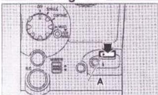
2. USING THE SHUTTER RELEASE (Fig. 17)
If the camera is ready for shooting, just press down the Shutter Release to take your picture.
Shutter Release (Fig. 17-A)
3. USING THE REMOTE-CONTROL SHUTTER RELEASE III (Fig. 18) Plug the Remote-control Shutter Release III into the camera's Remote-control Socket and, if the camera is ready for shooting, take your picture by pressing down its Release Button.
The hook on the grip is used for hanging the grip on the tripod's panning rod or some other convenient place when not in use.
If you are using the Remote-control Shutter Release III and have set the camera so that exposure will be more than 2 stops over or under, an electronic warning buzzer will turn on to warn you. To adjust the sound level of the buzzer, see the instructions on page 24.
* A Remote-control Shutter Release of the former type cannot be used. Be sure to use Remote-control Shutter Release Ⅲ.
4. SETTING THE SHUTTER SPEED SELECTOR (Fig. 19)
AE Mode Lock (Fig. 19-A)
Shutter Speed Selector (Fig. 19-B)
The possible settings are B, 8 - 1/400-second, and A. The flash will synchronize with all shutter speeds since the shutter is the interlens type.
* The Shutter Speed Selector cannot be set to intermediate speeds (speeds not shown on the scale.).
5. SETTING THE APERTURE SELECTOR (Fig. 20, 21)
The aperture is set by using the Aperture Selector located on the side of the lens barrel. Each step is provided with a click stop.
Aperture Scale (Fig. 20-A)
* The aperture can be set to intermediate values (values not shown on the scale.).
Since the GX680 III is an interlens-shutter type single-lens reflex camera, focusing is normally done with the aperture wide open. To preview the depth of field of your picture, just push down the Stop-down Lever located on the left hand side (when looking from the lens).
Stop-down Lever (Fig. 21-A)
Aperture Scale (Fig. 21-B)
Side aperture scale (Fig. 21-C)
Aperture Selector (Fig. 21-D)
6. TAKING FLASH PICTURES (Fig. 22, 23)
The GX680 III has a Hotshoe on the lens mounting and a Sync Socket on the body. Both are X-contacts. And since the shutter is the interlens type, flash will synchronize with all shutter speeds.
Hotshoe (Fig. 22-A)
Sync Socket (Fig. 23-A)
Shutter Release (Fig. 23-B)
* Use of M-class bulbs is not allowed. If used, the camera may be broken.
Caution:
You can use infrared synchronizers that are designed to synchronize cordless flash and camera, but practically all of these devices are equipped with built-in flash. A few of them, however, operate on built-in LEDs and slow-response receivers. Be careful when you use these time-lag units because they can sometimes fail to fire the flash.
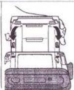
7. USING THE FINDER HOOD
(1) Expanding the hood (Fig. 24)
Just lift the hood cover up and it will spring into position by itself. Opening Notch (Fig. 24-A)
(2) Using the magnifier (Fig. 25)
When you look at the camera from the back, you will see a small lever near the Opening Notch in the right hand side of the Finder Hood. To flip up the Magnifier, just slide this lever to the right. To put it away, push down the Magnifier Board.
Putting away the Magnifier (Fig. 25-A)
Magnifier (Fig. 25-B)
Magnifier Lever (Fig. 25-C)
Flipping up the Magnifier (Fig. 25-D)
Collapsing the Finder Hood (Fig. 25-E)
(3) Folding down the hood
After putting the Magnifier away, place your thumbs against both sides of the Hood along the hinges and push them inward. That's all. The Hood will collapse and fold down by itself.
(4) Mounting and dismounting the finder hood (Fig. 26)
To dismount the Finder Hood, slide it toward the lens while pressing in two Finder Lock Release Buttons.
To mount, insert the projected portion of the Finder Hood into the recess on the camera body, and slide it toward the holder.
Finder Lock (Fig.26-A)
Dismounting (Fig. 26-B)
Mounting (Fig. 26-C)
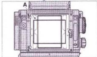
8. FRAMING YOUR PICTURE (Fig. 27)
The frames for horizontal and vertical composition are marked out with black lines in the viewfinder. These are used by revolving the Film Holder N to the desired position.
When the Film Holder III N is revolved into horizontal position, the Framing Indicator will appear in the top and bottom of the Finder and when it is revolved into vertical position, the Framing Indicator will appear in the
left and right sides of the Finder. Framing Indicator (Fig. 27-A)
- If you are using Instant Film Holder II, you can attach a framing mask to it that interlocks with the Finder's Framing Indicator.
- If you are using Instant Film Holder I, remember the Framing Indicator will remain fixed in vertical frame position only.
- If you are using Finder Screen for 6×6cm and 6×4.5cm size, you will not be able to see the Framing Indicator. Remember that the position where vertical Film Holder position is revolved 90° is the horizontal position.
Notice for mirror rejection:
- Since the mirror length is restricted by the body construction, depending on how far the bellows is drawn out, you may not be able to see the upper edge of the Finder image. With a 250mm focal-length lens or longer, the upper edge of the Finder image will be rejected even if the lens is set to infinity.
- On account of the restricted mirror, the upper edge of the Finder image may be rejected when camera-front movements are employed (particularly tilt ups and falls).
- Moreover, since the image circle of the GX680 III's interchangeable lenses have room to spare even when maximum camera-front movements are employed, the upper edge of the Finder image will register on the film even if it is rejected by the mirror. With a 50mm lens, the upper edge of the Finder image will be rejected when maximum camera-front movements are employed.
- To eliminate finder-image edge blur resulting from mirror rejection of the image when a long focal length lens is used, just set the camera front to the "rise" position.
9. FOCUSING THE LENS (Fig. 28)
While looking at the image in the viewfinder, bring it into focus by turning the Focusing Knobs in both sides of the camera.
After focusing, use the Focus Lock Lever to lock the focus in place. Focusing Knob (Fig. 28-A)
Focus Lock Lever (Fig. 28-B)
Braking Direction (Fig. 28-C)
* The GX680 III is equipped with a function for the front movements. To permit camera-front movements with the lens set to infinity, the interchangeable lenses of the GX680 III are not provided with an infinity stop.
IV. USING THE FILM HOLDER III N
- The Film Holder III N corresponds to the bar code system. The Film Holder III N is provided with a picture size mid-change warning and data printing outside picture frame functions. As a bar code film used, film speed (ISO) is automatically set and erroneous inner frame use warning can be made.
● The Film Holder III N allows 120/220 selections by changing the inner frame. Separate inner frames are used individually for 120 and 220.
● With Film Holder III N alone, the film can be set to the first frame.
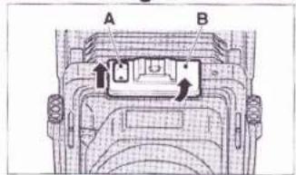
1. LOADING BATTERIES (Fig. 29)
Slide the Battery Compartment Cover (on the bottom of the Film Holder III N) to the arrow, and detach it.
Insert the batteries in the Battery Compartment with the plus and minus ends set as illustrated on the Battery Compartment, and close the Compartment Cover. When the battery mark lights on the LCD of the Film Holder, the batteries have been loaded correctly.
Batteries: CR2/DL CR2 (3V Lithium) ×2
* When the batteries are changed, all the set data will be erased. Be sure to reset. When the batteries are changed with the Film Holder mounted on the camera the power of which has been turned on, however, the data will be remained as they are.
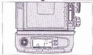
2. FILM HOLDER III N'S LIQUID CRYSTAL DISPLAY (LCD) (1) Film Holder III N alone (Fig. 30)
When the Film Holder III N has not been loaded with a film, the Exposure Counter will indicate "0", and the LCD will indicate type of the inner frame, picture size, battery mark, printing set and film speed (ISO). When the film winding completes and it is set to the first frame, the Exposure Counter will indicate "1".
* When a bar code film is used and "120/220" is blinking, the film has not agreed with the inner frame. Change the inner frame with a correct one. (Refer to page 20.)
* Before opening the Camera Back, make sure that the Exposure Counter indicates "0" or "E".
* For film advance starting, refer to page 21.
(2) Film Holder II N mounted on the camera (Fig. 31)
When the camera switch has been turned off, the LCD makes the same indications as the Film Holder III N alone.
Set the camera switch to ON (SINGLE, CONTINUE, or MULTI). The camera illustrations will light or blink, and battery mark will go out.
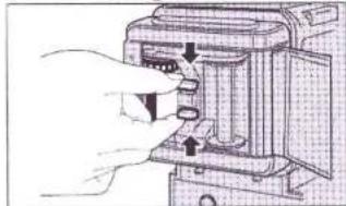
3. OPENING AND CLOSING THE CAMERA BACK (Fig. 32)
The Camera Back Lock is located on the back of the Film Holder III N (in the left hand side). To open the Camera Back, lift up the Camera Back Lock and push it down.
Erect and push down (Fig. 32-A, B)
To close it, replace the Camera Back with the Lock lifted up then snap down the Lock.
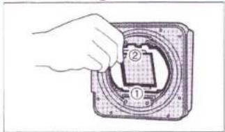
4. INSERTING AND EXTRACTING THE FILM HOLDER'S INNER FRAME (Fig. 33)
Squeeze the two center projections in the top and bottom of the Inner Frame toward the arrow. The lock pin with the Film Holder ⅢN will be released and the Inner Frame can be extracted.
To insert, squeeze the top and bottom projections toward the arrow, and push it in. Pull the Inner Frame center to make sure that the Inner Frame has been inserted and locked correctly in the Film Holder III N.
Upper surface of the inner frame (Fig. 33-A)
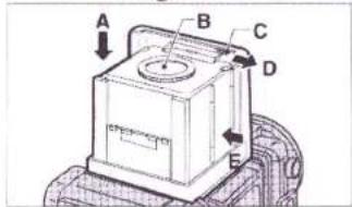
5. LOADING THE TAKE-UP SPOOL AND FILM (Fig. 34)
Insert the spool in the Take-up-Gear (located in the top of the Inner Frame) side and insert the film in the opposite side. Both spool and film are loaded by pulling up the Spool Holders provided on the bottom side of the Inner Frame.
Film Take-up Gear (Fig. 34-A)
Upper surface of the inner frame (Fig. 34-B)
Spool Holders (Fig. 34-C)
Bottom surface of the inner frame (Fig. 34-D)
* There are separate inner frames individually for 120 and 220 roll films. Use inner frames according to the film sizes.
6. POSITIONING THE FILM START MARK (Fig. 35)
With the photo-coupler in the Film Holder III N, GX680 III keeps constant check on the paper leader, trailer and film, and senses the bar code of a bar code film. With this system, the camera can position the first frame correctly without lining up start mark in the Inner Frame and the film start mark precisely. Just insert the leader paper into the slot on the take-up spool. The claw in the slot will then hook the round opening on the leader paper tip, causing the leader paper no longer pulled out. Wind the paper leader on the take-up spool up to such an extent as that the start mark appears in the left side.
Film-loading diagram (Fig. 35-A)
* In the case of 220 roll film, there is quite a bit of space between the tip of the paper leader and the start mark. You can therefore wind the
front end of the paper leader on the take-up spool and insert the Inner Frame into the Film Holder even if you cannot see the film start mark at all.
7. AUTOMATIC FIRST-FRAME SETTING
(1) Film Holder ⅢN mounted on the body.
To set the film to the first frame, insert the Inner Frame loaded with film into the Film Holder Ⅲ N, and close the Camera Back. Next:
- Set the Mode Switch to ON.
● Pull out the Sliding Cover causing the switch to turn ON.
- Close the camera back causing the switch to turn ON.
With all three switches turned on, the film will be automatically advanced and set to the first frame.
Further, even if the Mode Switch is set to OFF, the film can be advanced and set to the first frame by depressing the 1st FRAME SET Button on the Film Holder III N (With the dark slide inserted).
* The above system applies to both Inner Frames for 120 and 220 roll films.
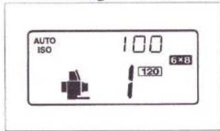
(2) Film Holder II N alone (Fig. 36)
Insert the Inner Frame loaded with film into the Film Holder III N and close the Camera Back.
Open the Mode Button Cover, and depress the 1st FRAME SET Button. The film will be advanced and set to the first frame. (This does not work when no sliding cover has been inserted.)
1st FRAME SET Button (Fig. 36-A)
8. SETTING FILM SPEED (ISO)
(1) When bar code films are used (Fig. 37)
Up/Down Dial (Fig. 37-A)
DATA/ISO Button (Fig. 37-B)
- Open the Mode Button Cover and keep depressing the DATA/ISO button for 2 seconds or longer. The Film Holder's LCD will cause the ISO number to blink. At the same time, blinks on the LCD of the body, indicating that the ISO number is being set.
- Revolve the Up/Down Dial toward Down side (counterclockwise) to let AUTO/ISO light. The ISO number of the film used last will blink. When the film used last is not a bar code film “-- -- --” will blink. Press in the DATA/ISO Button. “AUTO/ISO” will light for the ISO number allowing automatic ISO setting after the film is set to the first frame.
- When setting the film speed to a desired speed after the film has been set to the first frame, use the Up/Down Dial. Depress the DATA/ISO Button once again. The blinking ISO number will change to lighting,
indicating that the film speed has been set completely. After setting the film to the first frame automatically under AUTO/ISO mode, if ISO is set manually, "AUTO" will blink indicating that the set ISO number differs from the actual ISO number.
* When the loaded film is not properly stretched, validity date expired film is used, or incorrectly stored film is used, the data may not be read correctly.
* When "AUTO/ISO-- -- --" blinks after setting the film to the first frame (bar code reading error), the shutter lock actuates. Correct the ISO number setting manually. The camera will operate normally now.
(2) When conventional films are used (Fig. 38)
Up/Down Dial (Fig. 38-A)
DATA/ISO Button (Fig. 38-B)
Revolve the Up/Down Dial to set the film to a desired ISO number. Depress the DATA/ISO Button. The blinking ISO number will change to lighting, indicating that the film speed has been set completely.
※ Even if a wrong ISO number is set, result of photography will not be affected at all. However, when data are printed outside the picture frame, the density will be affected. In addition, the Exposure Warning Monitor will indicate a light measuring result under the set ISO number.
9. PRINTING DATA OUTSIDE PICTURE FRAME (Fig. 39)
The data under the set mode will be printed outside the picture frame. The printed data are DATE (year/month/day), TIME (hour/minute), DATE+TIME, DATA (exposure data) and SERIAL NUMBER (frame number).
Whenever each mode button is depressed, the indication will change sequentially. Stop depressing the button when the desired mode is indicated.
The set mode will light for 3 seconds after leaving your finger from the button, and then, go out. However, the LCD will indicate the printing mode indicating that the camera has been set to the desired mode.
* Limited data printing when using 6×4.5 format mask
When using the 6×4.5 format mask, one out of the following five data must be selected.
Year/month/day (DATE), Hour/minute (TIME), Year/month/day/hour/minute (DATE+TIME), "AV+TV", and Frame No.
The diagram shows all crystals displays in the "on" state. (Fig. 39-A) FRAME No. (Fig. 39-B)
1st FRAME SET (Fig. 39-C)
DATE/TIME/DATE + TIME (Fig. 39-D)
ISO/DATA/Setting of correction points in each setting mode (Fig. 39-E)
(1) Setting the date and time (Fig. 40)
Year/month/day (Fig. 41-A)
Hour/minute (Fig. 41-B)
Year/month/day + Hour/minute (Fig. 41-C)
Month/day/year (Fig. 41-D)
Month/day/year + Hour/minute (Fig. 41-E)
Day/month/year (Fig. 41-F)
Day/month/year + Hour/minute (Fig. 41-G)
No printing (Fig. 41-H)
① Press in the DATE Button for 2 seconds or longer.
② Year/month/day will be displayed, and "Year" will blink.
③ Set the Year number correctly with the Up/Down Dial.
④ Whenever pressing in the DATA/ISO Button, the number will change sequentially. The date and time will be shifted in the following order: Year → Month → Day → Hour → Minute → ISO number When the ISO number is displayed, the setting has been completed.
⑤ To set second to "0", press in the DATE Button after setting the minute. Second will be set to "0", the ISO number will be displayed, and thus, the setting completes. (Second will not be displayed.)
⑥ The LCD will indicate ISO number.
* For the date, an automatic calender (up to 2050) is employed.
* During setting the date, ⚠ will blink on the camera body.
(2) Setting the frame number (serial number) (Fig. 42)
FRAME No. Button (Fig. 42-A)
① Press in the FRAME No. Button for 2 seconds or longer.
② Whenever pressing in the DATA/ISO Button, the number will change sequentially.
③ Set the number with the Up/Down Dial.
④ Numbers 0 through 9, alphabets A through Z, and symbols (@ + - * = / < > _ | ∧), etc. can be selected in the top three digits.
⑤ Only numbers can be set in the bottom three digits, and start number can be set freely. One count is added per shot, and returns to 000 after counting 999. It is recommended that 1000 shots or more be arranged by combining them with date printings for your future convenience.
⑥ After ending the change, press in the DATA/ISO Button. The LCD will change indication from frame number to ISO number.
* During setting the frame number, ⚠ will blink on the camera body.
(3) Printing the exposure data (Fig. 43)
① Press in the DATA/ISO Button
② Whenever pressing in the DATA/ISO Button, the indication will change sequentially, and -- -- -- → AV+TV→ -- -- -- will be displayed. The data indicated on the LCD will be printed.
- ERRONEOUS INNER FRAME USE WARNING
(When bar code films are used) (Fig. 44)
Example: When the 220 inner frame is loaded with a 120 film (Fig. 44-A)
If "120/220" blinks on the LCD of the film holder after setting the film to the first frame, the inner frame has not matched with the type of film. Make sure that the loaded film is correct or not. If the inner frame loaded with a wrong film is used, incorrectly focused pictures will result.
- HOW TO READ TOTAL NUMBER OF SHOTS (Fig. 45)
Total Shots Sign (Fig. 45-A)
Total Shots Indicator Button (Fig. 45-B)
Press in the Total Shots Indicator Button. The camera illustration and total number of shots will be indicated (by blinking) in the order of lens, camera body and film holder. The indication will return to ISO number about 3 seconds later. Total number of shots will not be displayed with a conventional type lens and mounted.
Number of shots is displayed in the units of 100. The bottom two digits will always be indicated as "00". You may utilize these data to know whether the camera needs overhauling or periodical maintenance.
* Please, note that some cameras are indicating "200". This is due to factory test.
12.CHANGING FORMAT MASKS (Fig. 46)
Picture size can be changed by changing the mask of the Film Holder III N. First, apply the mask to the bottom of the film holder. Next, pull down the knob on the mask top, and lock the mask on the film holder. The installed mask size will be indicated on the LCD. If the indication is wrong, reinstall the mask correctly. When the mask is changed, the camera will sense number of exposures, and sound final frame warning buzzer in the same manner as 6×8.
| Number of exposures | ||
| Mask | 120 | 220 |
| 6×7 | 10 exp. | 20 exp. |
| 6×6 | 12 exp. | 24 exp. |
| 6×4.5 | 16 exp. | 32 exp. |
* Be sure to change the mask before setting the film to the first frame. Mid-roll mask change is not allowed. ⚠ will blink on the LCD of the camera body, the size indication will blink on the LCD of the film holder, and the shutter lock will actuate.
* When the format mask is changed, change the focusing screen also by checking the size. (Refer to page 25.)
* When the 6×4.5 format mask is mounted, the data print setting will be totally cleared. Reset them.
* The GX680 III has been engineered for multi-format capability in addition to its standard 6×8 format. When using the camera at wide open lens apertures with the optional multi-format masks installed (other than 6×8 format), the frame edges may appear to be slightly soft along certain parts of the frame. This will not affect picture quality.
13. LCD BACK LIGHT ILLUMINATION (Fig. 47)
When the Call/Light Button on the camera body or film holder is pressed in after mounting the Film Holder III N on the camera, both the camera body's and film holder's LCDs will light. (The film holder's LCD will light by itself alone when the Call/Light Button is pressed in even if the film holder is not mounted on the camera.) Whenever the Call/Light Button is pressed in, the LCD will light for about five seconds. When the LCD Light Button is pressed in continuously for more than five seconds, the LCD will keep lighting, and the LCD illumination goes out when your finger off.
Call/Light Button (Fig. 47-A)
14. FILM TYPE INDICATION (Fig. 48)
When a bar code film is used, the type of film will be displayed.
① Set the ISO indication to AUTO/ISO.
② Press in the Call/Light Button and FRAME No. Button simultaneously for two seconds.
③ The LCD will display the type of film (black/white, color negative/color reversal) ("BW, CN, CR" will blink).
④ Press in the Call/Light Button. The type of film will light, and thus, the setting completes.
15. USING THE MEMO SPACE AND FILM REMINDER SLOT (Fig. 49)
The white Memo Space is used for jotting down exposure notes, etc. Penciled notes can be erased with a rubber eraser.
The Film Reminder Slot is used for inserting the top cover of the film box so that you won't forget which film you are using.
Film Reminder Slot (Fig. 49-A)
Memo Space (Fig. 49-B)
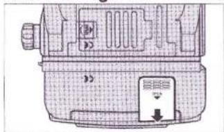
16. SLIDING IN, SLIDING OUT, AND PUTTING AWAY THE DARK SLIDE (Fig. 50)
Fit the leading edge of the Dark Slide to the slot guide and push it all the way
Lock Pin (Fig. 51-A)
in. The slot inlet is marked white so that you can see it even in dim light. To pull out the Dark Slide, hold its finger grip.
* When the Film Holder III N is dismounted from the camera, a safety device locks the Dark Slide so that it cannot be pulled out.
* The Dark Slide has no front or back side (both sides are the same). If the Film Holder III N is dismounted from the camera but you want to pull out the Dark Slide, just press in the Lock Pin and pull it out.
When taking pictures, pull the Dark Slide out and keep it in the Dark Slide Pocket so that you won't misplace or lose it. (Fig. 51)
17. WINDING AND UNLOADING THE FILM (Fig. 52)
Since the GX680 III/GX680 III S is a motor-driven camera, the film will automatically advance to the next frame each time the Shutter Release is depressed. After insuring that the Exposure Counter shows the "E" sign, open the Camera Back, take out the Film Holder's inner frame, and unload the film. Next, to prevent the film from loosening, seal it tightly with the End Seal.
V. CAMERA MOVEMENTS
* GX680 III S has no camera movement functions. In normal photography, the lens optical axis passes through the center of the film at right angles. Camera movements are used to take the optical axis away from film center, to cross the lens optical axis and film surface diagonally, etc. to control image perspective and sharpness. They let you change the shape of objects in your picture, shoot subject that have depth to them but which are sharply focused from one end to the other, as well as control the position of objects in your picture without changing camera position or angle.
The main camera movements are the tilt and swing which involve an optical twist and turn, and the rise, fall, and shift which involve a parallel movement of lens and film, and the generic term that encompasses all these deviations from normal is "camera movement".
1. RISE AND FALL (Fig. 53)
These movements are made by loosening the Rise/Fall Knobs located on both sides of the lens mounting and raising or lowering the lens face parallel with the line of the film plane. The rise is an upward, and the fall a downward movement. They are generally used to make tall buildings appear vertical in your picture and to improve the figure of portrait subjects.
Rise/Fall Knob (Fig. 53-A)
2. SHIFTS (Fig. 54)
These movements are made by loosening the Shift Knob and moving the camera front to the left and right parallel with the line of the film plane by pushing the Shift Frame. It is used to change the position of objects in your picture without moving the camera.
It can also be used to correct the position of the optical axis when using the technique called "swing".
Shift Frame (Fig. 54-A)
Shift Knob (Fig. 54-B)
3. TILTS (Fig. 55)
To tilt, loosen the two Tilt Knobs, one on each side of the camera, and turn the camera front up or down. These movements are used to control the top-to-bottom sharpness of subjects having depth without stopping down the aperture.
Tilt Knobs (Fig. 55-A)
4. SWINGS (Fig. 56)
To swing, push the Swing Lever (located next to the Focusing Knob on the left side of the camera body) and, at the same time, turn the camera front to the left or right. These movements are generally used to adjust right-to-left sharpness, but they can also be used to control image perspective.
Swing Lever (Fig. 56-A)
* The movements described in the foregoing paragraphs are almost always used in combination. Regarding details concerning the principles and techniques involved, please refer to a more complete treatise on the subject. Camera-magazine publishers should be able to tell you where you can obtain such material.
* Be sure to tighten the camera-movement knobs before you start taking pictures. If the knobs are loose, you may jiggle the camera when you take your picture.
* After you are through taking pictures, be sure to return all of the parts used to employ camera movements back to their original positions. If you don't, you may get partly-fuzzy pictures, that is, pictures with degraded edges.
* With a standard bellows, you won't be able to use full camera movements if it is compressed. The best thing you can do in such cases is to change to a wideangle bellows.
VI. OTHER PROCEDURES
1. ADJUSTING THE SOUND LEVEL OF THE INCORRECT-EXPOSURE WARNING BUZZER (Fig. 57)
If the exposure you have set is more than two stops over or under, an electronic warning buzzer (700 Hz) built in the grip of the Remote-control Shutter Release III will turn on and buzz intermittently for five seconds. You can adjust its sound level if you wish. To reduce the volume of the sound or switch it off, turn the adjuster to the right, and to increase the volume, turn it to the left.
High (Fig. 57-A)
Low (Off) (Fig. 57-B)
To avoid damaging the buzzer, however, do not set the adjuster beyond the left and right stop points (marked with dots) (Fig. 57-C).
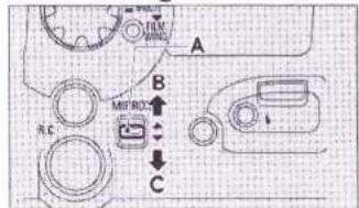
2. SHOOTING WITH THE MIRROR UP (Fig. 58)
If you are taking long-exposure shots such as close-ups, or if you want to avoid the time lag of the mirror movement to shoot a fast-moving subject, just shoot with the mirror up. This is the way to do it: After focusing the lens through the Finder, bring the mirror up by pushing up the MIRROR Up/Down Switch then take your picture. After shooting with the mirror up, bring the mirror down again by pushing the Switch down.
MIRROR Up/Down Switch (Fig. 58-A)
Mirror up (Fig. 58-B)
Mirror down (Fig. 58-C)
If you are using a large size lens mounted on a Linhof board on the GX680Ⅲ, you'll have to shoot with the mirror up. In this case, you'll need an LF Lensboard Adapter. (Refer to page 25.)
3. USING SYNC TEST BUTTON (Fig. 59)
This button lets you test from camera position the flash that is clipped into the Hotshoe or connected to the Sync Socket with a cord. It can be used to measure the exposure range of the flash and to test-fire it without using the Shutter Release, a well as to check sync cord severance and faulty cord connection.
Sync Test Button (Fig. 59-A)
* Synchronization test with the Sync Test Button consists of checking the conductivity up to the Sync Socket. Since the shutter's X-contact is not involved, testing does not include shutter synchronization. To be on the safe side, therefore, it is always best to make a reliable test with the Shutter Release and with the Camera Back open before loading film in the camera.
4. CHANGING THE FOCUSING SCREEN (Fig. 60)
The camera's standard focusing screen is an all matte screen with a microprism center. For copy work and merchandise photography that attach importance to horizontality and perpendicularity, a lattice-type screen marked into 10-mm squares is available as an optional accessory (extra-cost required).
To change screens, remove the Finder Hood, release the Screen-holding Lever, lift up the screen frame, and insert the screen.
Screen-Holding Lever (Fig. 60-A)
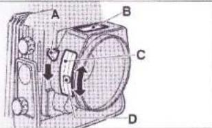
5. CHANGING THE BELLOWS (Fig. 61, 62)
If you are using camera-front movements, use the Wideangle Bellows and if you taking close-ups, use the Long Bellows.
To change bellows, release the Lock Lever (located in the right hand side of the back of the lens mounting seat when seen from the film holder) then push the Front Side Sliding Lever upward and dismount the camera front.
Lock Lever (Fig. 61-A)
Front Side Sliding Lever (Fig. 61-B)
Next, push the Back Side Sliding Lever upward and dismount the bellows from the camera body.
Back Side Sliding Lever (Fig. 62-A)
To mount the bellows, repeat the same steps in reverse then push down the Front and Back Sliding Levers to lock the bellows to the camera body.
Be careful how you mount the bellows. The Stand-by Monitor will not operate even if it is not mounted correctly.
6. USING THE EXTENSION RAILS (For taking close-ups) (Fig. 63)
Like a view camera, the close-up shooting scope of the GX680 Ⅲ can be expanded by using its extension rails.
Loosen the Knob Screws on the front ends of the Focusing Rails and remove the Front Bar.
Next, screw the Extension Rails (Optional accessory - Requires an extra-cost) to the Focusing Rails then screw the Front Bar.
Knob Screw (Fig. 63-A)
Front Bar (Fig. 63-B)
7. CHANGING THE FINDER HOOD'S MAGNIFYING GLASS (Fig. 64)
The GX680 III's Finder Hood is equipped with a 2.5×-magnification, -1 diopter magnifying glass. Magnifying glasses ranging from -4 to +3 diopters are also available (Optional accessory - Requires an extra-cost) so that you can choose one that exactly fits your eyesight. The magnify-
ing glass is secured to the mounting plate by means of a bayonet screw. To dismount, turn it to the left.
Diopter-correction lens (magnifying glass) (Fig. 64-A)
Turn left to dismount (Fig. 64-B)
8. TAKING HAND-HELD SHOTS (Fig. 65)
To keep the camera still when taking hand-held shots, hold it firmly with both hands, focus the lens with the left hand and operate the Shutter Release with the right thumb.
You can keep it even steadier by using the camera's "Neckstrap III" (Optional accessory - Requires an extra-cost).
9. TAKING PICTURES WITH INSTANT FILMS (Fig. 66)
The GX680Ⅲ's Instant Film Holders will let you take pictures with Fuji FP-100C (color)/ FP-100B(mono-chrome) instant films and other peel-apart type instant films of the same size.
To shoot with Instant Film Holder I, you'll have to set the camera's Mode Switch to MULTI.
To shoot with Instant Film Holder II, you can set the Mode Switch to either SINGLE, CONTINUE, or MULTI.
Instant Film Holder (Fig. 66-A)
Lock Lever (Fig. 66-B)
10. USING LARGE SIZE LENSES
The LF Lensboard Adapter (optional extra) lets you take pictures with large-size lenses mounted on a Linhof Technika type lensboard.
However, shooting must be done with the mirror up because the shutter system differs. Set the Mode Switch to MULTI. Advance the film with the Film Wind Button. The Film Wind Button operates under the MULTI mode only. With the LF Lensboard Adapter used, ▲ of the camera's LCD and the lens illustration of the film holder's LCD will blink, but these do not mean any trouble. You may use as it is.
The large-size lenses that can be used:
With standard rails: Fujinon CM 180, A 180, SF 180
With extension rails: Fujinon CM 210, CM 250, A 240, T 300
* If you are using lenses other than those just mentioned, check to make sure the lens back element does not protrude from the back of the lensboard because it can knock against the mirror and damage it.
CAMERA CARE
Your camera is a precision instrument that needs careful handling. The following will show you how to care for your camera.
- Wipe off rain and water droplets from your camera with a piece of clean and dry cloth. After taking pictures in salt-water atmosphere near the ocean, wipe off the camera exterior with a piece of clean cloth so as to thoroughly remove the salt content.
- Do not use solvents such as thinner or alcohol to remove smudges from your camera. Remove dust with a brush and an air blower, and wipe off the camera exterior with a piece of lint-free soft cloth such as a piece of silicon cloth.
- Remove dust and debris from the lens glass and viewfinder with a lens brush and an air blower. Fingermarks and smudges are removed by wiping gently in a circular motion with a clean wad of cotton moistened with lens cleaning fluid (commercially available). Always start from the center then gradually move out to the edges.
- Soil and dust in the contacts are usually the cause of all electrical troubles. If any symptom pointing to electrical trouble is detected, check the battery contacts and other contact points for battery leakage, hand grease, rust from salt and harmful gases, and dust and debris.
If the symptom persists even after cleaning, bring the camera to your nearest Fuji's Service Station for inspection.
As mentioned above, dust and debris in the contacts cause a poor contact. Remove dust and debris with a brush and an air blower.
- The mirror and the backside of the focusing screen are prone to abrasion. Keep your fingers off these parts.
- Immersing your camera in water will usually result in damage that is beyond repair. In the event you drop your camera in water, take it immediately to your nearest Fuji's Service Station to see what can be done.
- To keep your camera in top shape at all times, have it checked by a qualified technician about once a year or at least once in two years. If you haven't used your camera for a long time, or if you are using it in an important assignment, be sure to check it thoroughly and take some test shots before using it.
■ A word on the LCD
- At about 60°C the LCD might blackout, but it will return to normal as soon as the camera is brought back to where the temperature is normal.
- In low temperature, the LCD might react sluggishly, but this is a natural phenomenon and can be ignored.
■ A word on the battery
■ The operating temperature range
■ Storage Precautions
- Any batteries have such a nature as to drop their performance in low temperature, but it recovers as soon as it returns to normal temperature. When taking pictures in low temperature, use new batteries, keep spare batteries in your pocket to warm them up, and change the loaded batteries with those kept warm in your pocket alternately. If the loaded batteries are spent, the camera may not operate in low temperature.
- When the battery checker changes to “◀” mark, replace the batteries with new ones.
● The operating temperature range of the camera is from -10^ to +40^ . - In hot weather, do not leave your camera in a closed compartment of your car and in moist places except temporarily for a very short time.
- Keep the camera where it will be safe from moisture, heat, and dust. Be sure to put the lens cap on the lens.
- Do not store it in a wardrobe drawer because the gas of naphthalin or other insecticides can cause damage to the camera and film.
SPECIFICATIONS
- Description
6 × 8cm format, interlens-shutter, single-lens reflex camera corresponding to bar code system
Frame Size
Multi-format; revolving back (for horizontal and vertical frame exposure) 6 × 8cm format (56 × 76mm actual picture size)
6 × 7cm format (56 × 69mm actual picture size)
6 × 6cm format (56 × 56mm actual picture size)
6 × 4.5cm format (56 × 41.5mm actual picture size)
Film
| 6×8 | 6×7 | 6×6 | 6×4.5 | |
| 120 half-length roll film | 4 exposures | 5 exposures | 6 exposures | 8 exposures |
| 120 roll film | 9 exposures | 10 exposures | 12 exposures | 16 exposures |
| 220 roll film | 18 exposures | 20 exposures | 24 exposures | 32 exposures |
Instant film (FOTORAMA FP-series instant films and other peel-apart instant films of the same size)
Separate film holders for instant films
- Lens
Interchangeable (Currently available optional lenses can be used)
Standard lens: EBC Fujinon GX M 135mm, f/5.6
Mounting: By means of interchangeable lensboards
Filter diameter: Thread diameter = 82mm; Outer diameter = 85mm
The GX M (for type Ⅲ) lens is equipped with a memory to store total number of shots data (lens alone).
- Shutter
1, electrically-controlled interlens shutter; B, 8 - 1/400-sec. shutter speeds; provided with aperture selector and depth of field preview lever; interchangeable lenses' built-in motor cocks and releases the shutter.
● Synchronization
X-contact: Flash synchronizes with all shutter speeds (M-class bulbs cannot be used)
Hotshoe (on lens mounting): Provided with sync socket (on camera body) and sync test button
● Shutter Release
Electromagnetic operation
Special remote-control shutter release Ⅲ (with 1m or 5m long cord) (optional accessory)
- Mirror
Motorized auto return (built-in the camera body); mirror can be raised or lowered by electric switch.
● Multiple Exposure
By setting the mode switch to MULTI; automatic film advance after multiple exposure by pressing in camera's film wind button.
- Viewfinder
Single-lens reflex waist-level screen
Interchangeable focusing screens (standard screen is a matte screen with microprism center)
Standard finder hood is the collapsible, one-touch folding and erecting type
- Equipped with a 2.5×-magnification, -1 diopter magnifier for fine focusing
- Interchangeable with -4, -3, -2, 0, +1, +2 and +3 diopter magnifiers (optional accessories)
Angle finder II (optional accessory)
Field of view: 97% (covers 8 × 8cm format with room to spare)
Framing indicator appears in the finder when the film holder is revolved to indicate vertical and horizontal positions of the mask.
- Focusing
By extending and compressing the bellows by means of focusing knobs
on both sides of the body (provided with focus lock lever)
- 65mm maximum bellows extension
• Provision for using 40mm and 80mm extension rails - Interchangeable bellows (long and wide-angle bellows are optional accessories)
● Camera Movements (Do not apply to GX680 III S)
Equipped for employing camera-front movements
• Shifts: 15mm left and right
- Rise: 15mm
• Fall: 13mm
• Swings: 12° left and right
- Tilts: 12^ up and down
* Depending on the lens being used, maximum movements may not be possible if shifts and turns are combined.
● Exposure Monitor
Provides over/underexposure warning by directly measuring the light intensity reflected by the film surface (EV5 \~ 19, ISO 100).
- Camera's LCD indicates exposures
- Over/underexposure warning by means of an electronic buzzer when using the remote-control shutter release
- Camera's LCD
Power on or off, shooting stand-by, battery checker, incorrect exposure warning, abnormal camera behavior
● Audible Electronic Warning
Last frame, incorrect exposure (when using remote-control shutter release III; adjustable buzzer volume)
● Power Source
CR 123A /DL 123A (3V Lithium) ×3 (9V)
- Others
- Spirit level
- LF lensboard adapter (optional) which permits shooting with large-size lenses mounted on Linhof Technika type lensbaords (Shooting is done with the mirror up)
● Dimensions & Weight
GX680Ⅲ :188(W)×222(L)×213(H)mm; 2690 g
GX680ⅢS:188(W)×222(L)×187(H)mm;2350g
(with collapsible finder hood, standard bellows, and finder screen: without batteries)
GX680Ⅲ :188(W)×274(L)×213(H)mm; 4070 g
GX680ⅢS:188(W)×274(L)×187(H)mm;3730g
[Camera body + standard accessories, Fujinon GX M 135mm lens and film holder III N (with inner frame 120): without batteries]
● Accessories (included)
Collapsible finder hood, standard bellows, finder screen, front and back body caps, three lithium batteries
● Film Holder III N
Revolving interchangeable
120/220 switching: Changing the inner frame
- Automatic first frame set by itself; with film speed setting function (ISO 25 up to 3200 in every 1/3 step)
- Corresponding to bar code system films (Automatic ISO reading, 120/220 sensing, type of film sensing)
- Built-in outside picture frame data printing (year-month-day/hour-minute, shooting data, exposure compensation (only when AE finder is used), serial number)
- LCD indications (Exposure counter, date, shooting data, picture size, battery checker, total number of shot counter, 120/220 discrimination, camera self-check warning)
• LCD back light illumination (EL type)
• Multi-format mask (optional) - With dark slide pocket, memo space, film reminder slot
• Power source: CR2/DL CR2 (3V Lithium) ×2 (6V)
● Film advancing
Automatic; No start-mark setting required
• Motor-driven (S.C.I/M switching over)
- With last frame notifying buzzer
• Automatic winding after exposing the last frame
- Film advancing speed: About one second per frame (when 6 × 8 format is used)
● Exposure Counter
Additive type counter on LCD (Number of exposures, Film running, "E" sign, Total number of shots of film holder alone.)
* Specifications and performance are subject to change without advance notice.