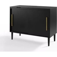
Everett CF1103 - Lecteur multimédia Crosley - Notice d'utilisation et mode d'emploi gratuit
Retrouvez gratuitement la notice de l'appareil Everett CF1103 Crosley au format PDF.


| Type de produit | Console multimédia / Meuble TV |
| Marque | Crosley |
| Modèle | Everett CF1103 |
| Matériaux | Panneaux de particules, quincaillerie métallique |
| Poids maximum supporté (TV) | 23 kg (50 lbs) maximum pour le téléviseur |
| Compartiments de rangement | 2 portes, 1 étagère fixe, 2 étagères réglables |
| Nombre de pieds | 4 pieds métalliques |
| Finition | Similaire au bois (couleur naturelle) |
| Assemblage requis | Oui, avec outillage fourni (clé Allen, clé à fourche) et tournevis cruciforme (non fourni) |
| Kit de sécurité inclus | Oui, sangle anti-bascule avec cheville et vis |
| Nettoyage et entretien | Chiffon doux et sec, éviter les produits abrasifs |
| Usage prévu | Rangement d'équipements audio/vidéo (lecteur multimédia, console de jeux, etc.) |
| Pays de fabrication | Non spécifié |
| Dimensions (approx.) | Environ 120 x 45 x 60 cm (L x P x H) - Les dimensions exactes sont dans le manuel |
| Poids (approx.) | Environ 25 kg (emballé) |
FOIRE AUX QUESTIONS - Everett CF1103 Crosley
Questions des utilisateurs sur Everett CF1103 Crosley
0 question sur cet appareil. Repondez a celles que vous connaissez ou posez la votre.
Poser une nouvelle question sur cet appareil
Téléchargez la notice de votre Lecteur multimédia au format PDF gratuitement ! Retrouvez votre notice Everett CF1103 - Crosley et reprennez votre appareil électronique en main. Sur cette page sont publiés tous les documents nécessaires à l'utilisation de votre appareil Everett CF1103 de la marque Crosley.
MODE D'EMPLOI Everett CF1103 Crosley
CROSLEY
FURNITURE
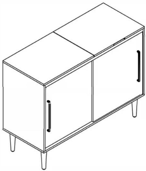
Media Console CF1103
natural_image
Line drawing of a simple cabinet with four legs and two doors, no text or symbols presentPART LIST
| A | 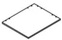 | B | 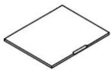 | C | 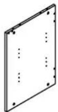 | D |  | E |  |
| Left Top Panel1 PC | Right Top Panel1 PC | Left Panel1 PC | Right Panel1 PC | Bottom Panel1 PC | |||||
| F | 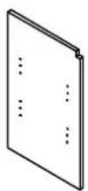 | G | 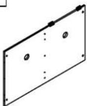 | H | 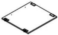 | I | 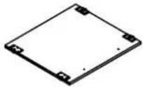 | J | 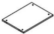 |
| Dividing Panel1 PC | Back Panel1 PC | Left Door Panel1 PC | Right Door Panel1 PC | Fixed Shelf1 PC | |||||
| K | 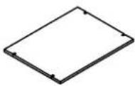 | L |  | M |  | N | 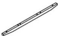 | O | 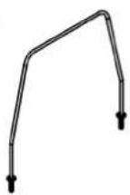 |
| Adjustable Shelf2 PCS | Top Rail1 PC | Leg4 PCS | Bottom Rail1 PC | Metal Wire4 PCS | |||||
HARDWARE LIST
#1 M6*13 M6*13 | #2 | #3 ∅7*35mm ∅7*35mm | #4 ∅15*12mm ∅15*12mm | #5 ∅8*30mm ∅8*30mm | |||||
| Allen Bolt8 PCS | Hex Nut8 PCS | Cam Bolt31 PCS (Extra 2) | Cam Lock31 PCS (Extra 2) | Wood Dowel26 PCS (Extra 2) | |||||
| #6D7*∅3.5*12 | #7 | #8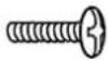 ∅9mm*5/32"*1" ∅9mm*5/32"*1" | #9 ∅8*5*16mm ∅8*5*16mm | #10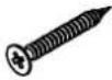 D8*∅4*38 D8*∅4*38 | |||||
| Short Screw10 PCS (Extra 2) | Handle2 PCS | Round Head Bolt4 PCS | Shelf Pin8 PCS | Screw4PCS (Extra 1) | |||||
#11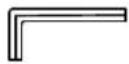 | #12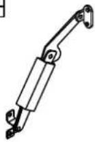 | #13 | #14 | ||||||
| Allen Wrench1 PC | Spring Hinge1 PC | Open End Wrench1 PC | Safety Strap Kit1 SET |
ADDITIONAL TOOLS (Not Provided)
Note: It is not recommended to use power tools during assembly.
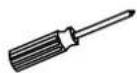
Phillips Head Screwdriver
Step 1. Insert cam bolts (part #3) into pre-drilled holes of left top panel (part A), left panel (part C), right panel (part D), dividing panel (part F) and back panel (part G) using phillips head screwdriver. NOTE: Do not overtighten cam bolts. Stop tightening once threads on cam bolt are no longer visible.
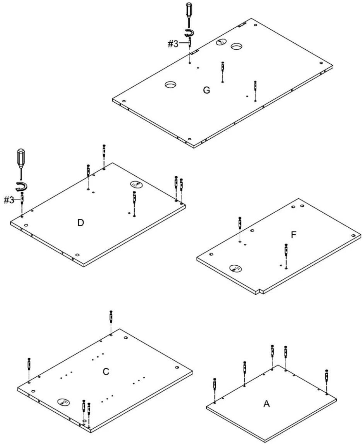
3 ×20
Step 2. Attach handles (part #7) to left door panel (part H) and right door panel (part I) using round head bolts (part #8) and phillips head screwdriver.
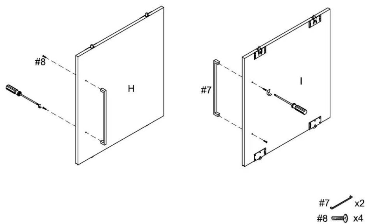
7 x2
8 x4
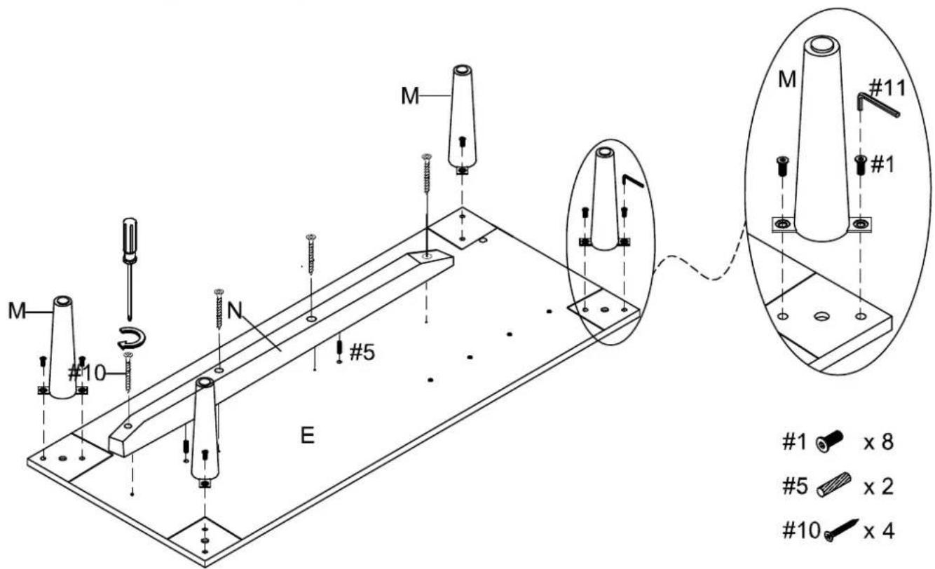
Step 3. Attach bottom rail (part N) to bottom panel (part E) using wood dowels (part #5), screws (part #10) and phillips head screwdriver. Attach legs (part M) to bottom panel (part E) using allen bolts (part #1) and allen wrench (part #11).
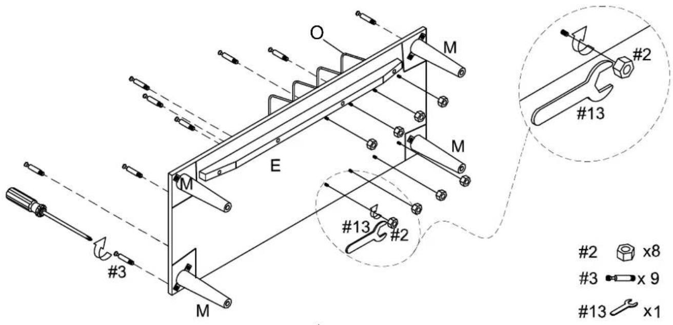
Step 4. Attach metal wires (part O) to bottom panel (part E) using hex nut (part #2) and open end wrench (part #13). Insert cam bolts (part #3) into pre-drilled holes of bottom panel (part E) using phillips head screwdriver as shown. NOTE: Do not overtighten cam bolts. Stop tightening once threads on cam bolt are no longer visible.
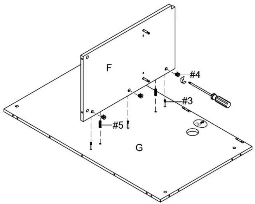
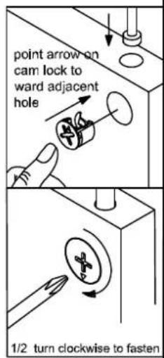
Step 5. Attach dividing panel (part F) to back panel (part G) using wood dowels (part #5), cam locks (part #4) and phillips head screwdriver. NOTE: Cam locks must rotate full 180°. See pictured insert.
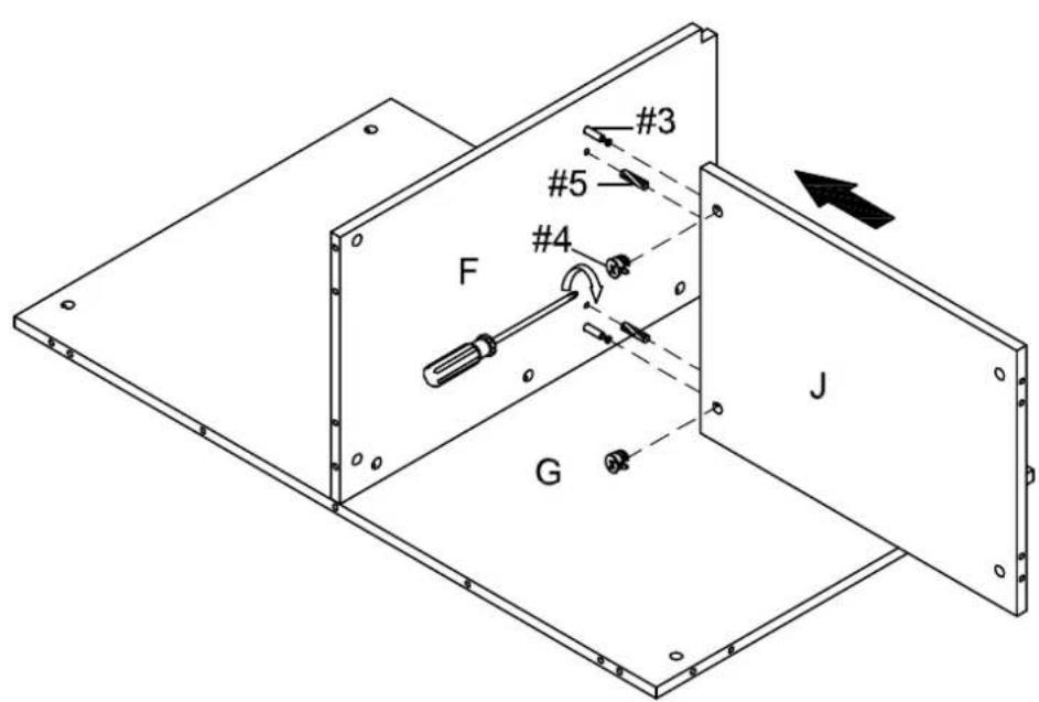
Step 6. Attach fixed shelf (part J) to dividing panel (part F) using wood dowels (part #5), cam locks (part #4) and phillips head screwdriver as shown.
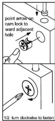
NOTE: Cam locks must rotate full 180°. See pictured insert.
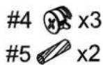
4 x2
5 x2
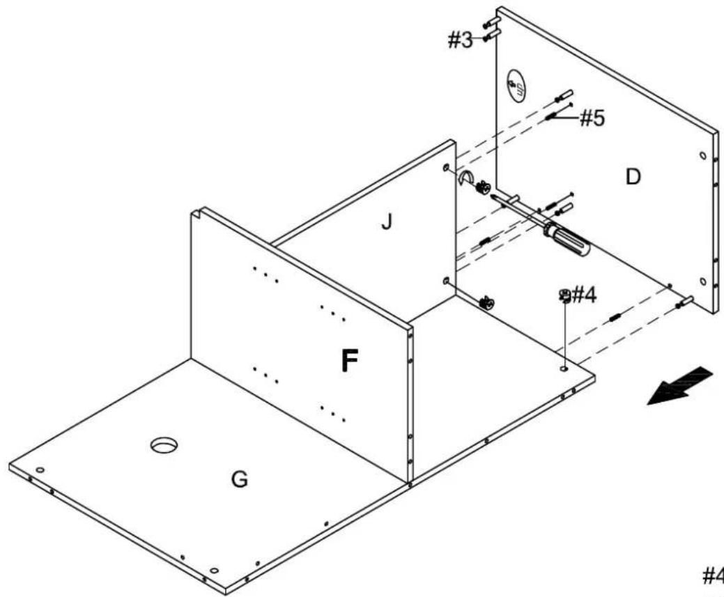
Step 7. Attach right panel (part D) to back panel (part G) and fixed shelf (part J) using wood dowels (part #5), cam locks (part #4) and phillips head screwdriver.
NOTE: Cam locks must rotate full 180°. See pictured insert.
4 x4
5 x4
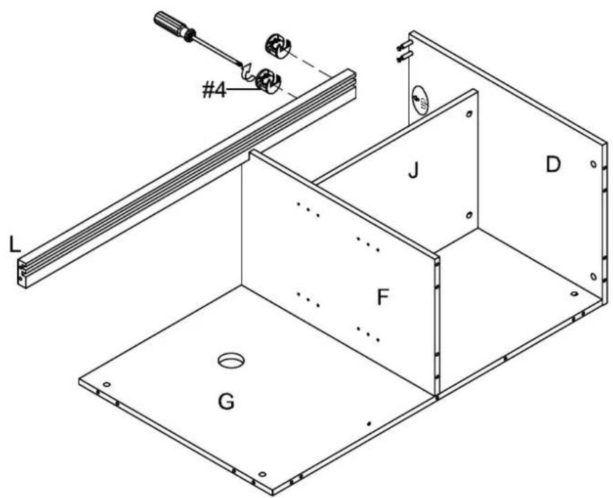
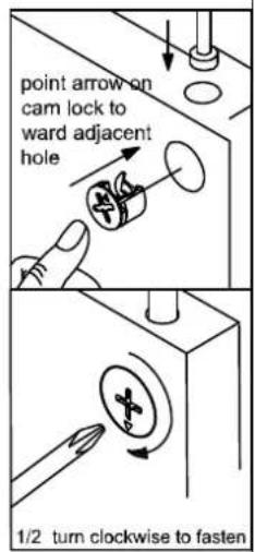
Step 8. Attach top rail (part L) to right panel (part D) using cam locks (part #4) and phillips head screwdriver.
NOTE: Cam locks must rotate full 180°. See pictured insert.
4 x2
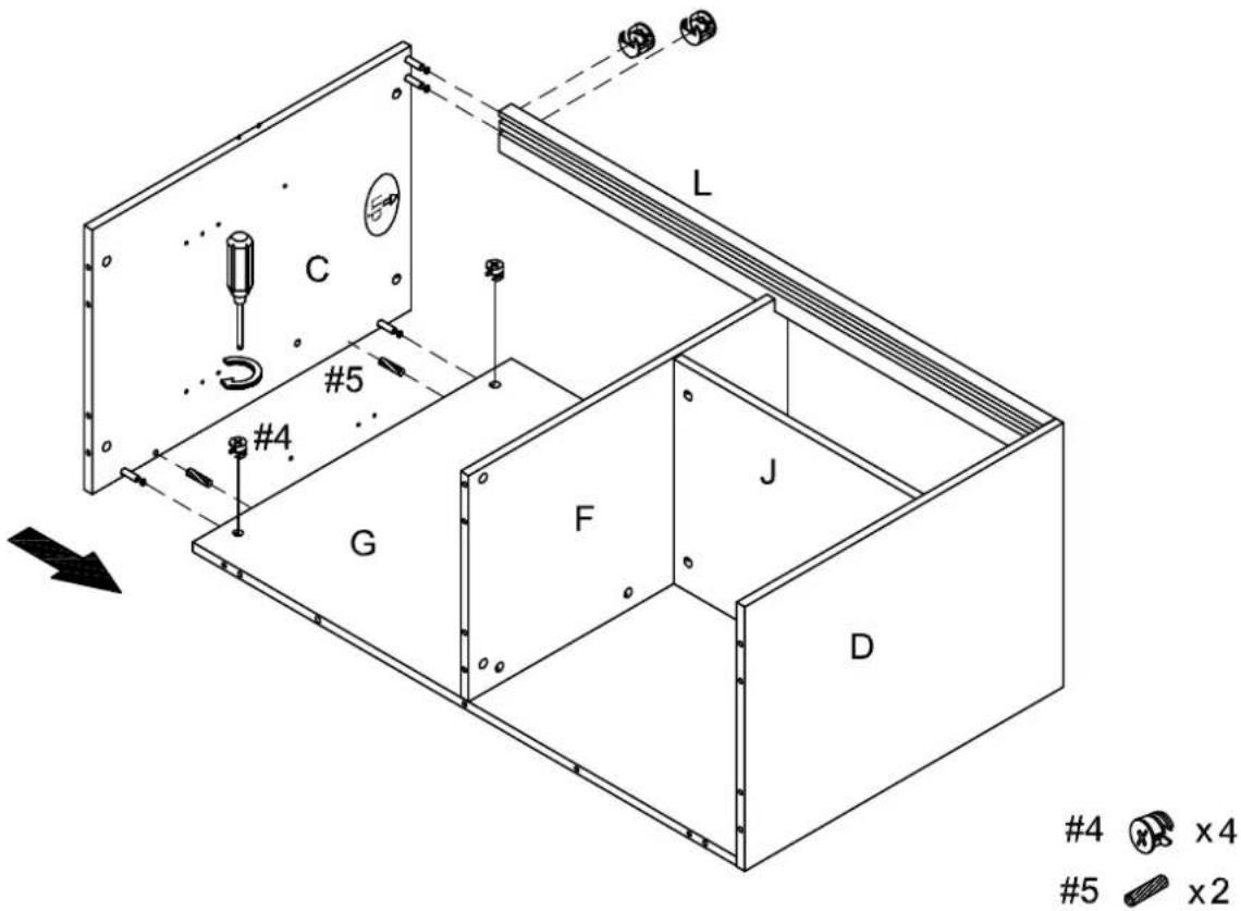
Step 9. Attach left panel (part C) to top rail (part L) and back panel (part G) using wood dowels (part #5), cam locks (part #4) and phillips head screwdriver. NOTE: Cam locks must rotate full 180^ . See pictured insert.
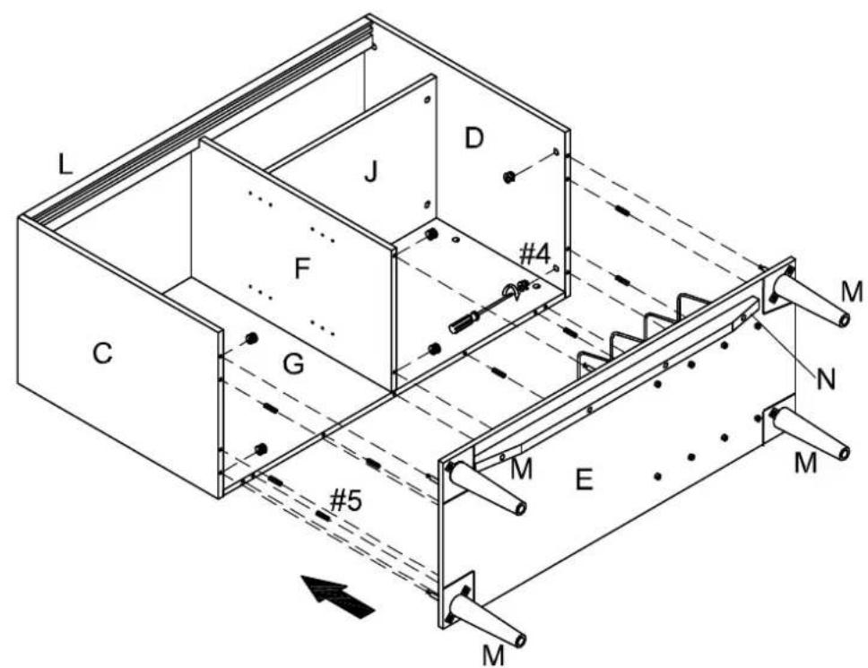
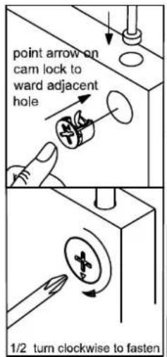
Step 10. Attach bottom panel (part E) to assembled unit (parts C, D, F & G) using wood dowels (part #5), cam locks (part #4) and phillips head screwdriver. NOTE: Cam locks must rotate full 180°. See pictured insert.
4

x6
5

x8
Step 11. With two people, carefully lift and turn unit upright. Insert cam locks (part #14) into pre-drilled holes on the bottom of the back panel (part G) and lock using phillips head screwdriver. NOTE: Cam locks must rotate full 180^ . See pictured insert.

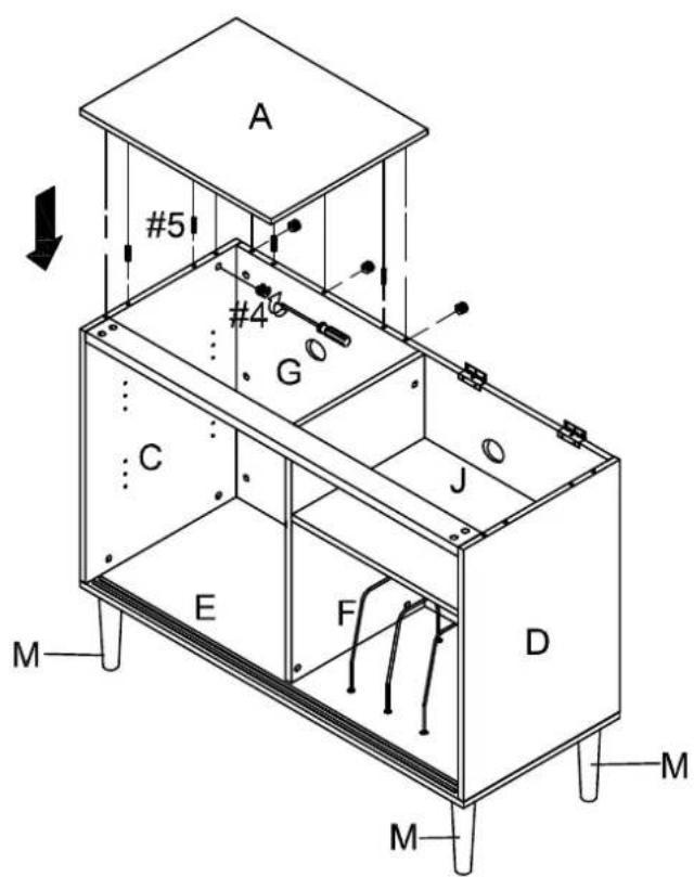
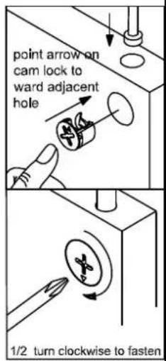
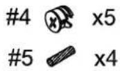
Step 12. Attach left top panel (part A) to left panel (part C) and back panel (part G) using wood dowels (part #5), cam locks (part #4) and phillips head screwdriver. NOTE: Cam locks must rotate full 180°. See pictured insert.
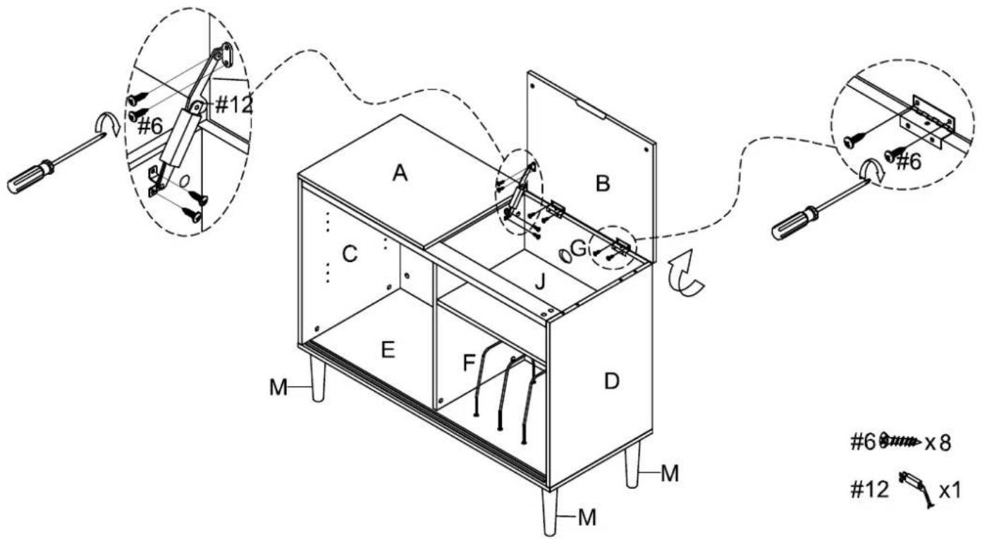
Step 13. Attach right top panel (part B) to back panel (part G) using short screws (part #6) and phillips head screwdriver. Then attach right top panel (part B) to dividing panel (part F) using spring hinge (part #12), short screws (part #6) and phillips head screwdriver.
Step 14. Insert shelf pins (part #9) into desired position and slide adjustable shelves (part K) into place.
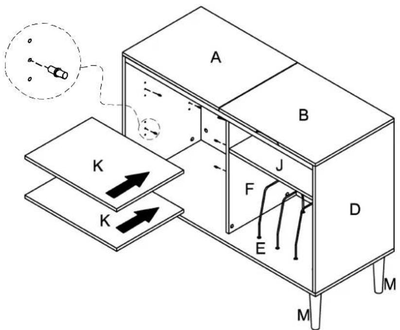
9 ×8
Step 15. Press the upper door pins on right door panel (part I) up. Install right door panel (part I) to inner runner of pre-assembled cabinet as shown.
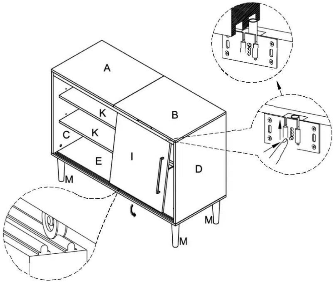
Step 16. Press the upper door pins on left door panel (part H) up. Install left door panel (part H) to outer runner of pre-assembled cabinet as shown. NOTE: If moving, please lift with two people. Do not drag.

| #15 | A | B | C | D | E |
 |  |  |  |  |  |
| D8*3/4" | D8*1-1/2" | ||||
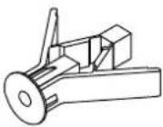
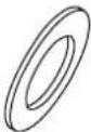
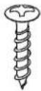
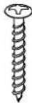
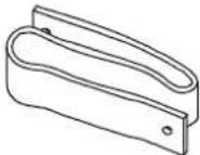
| Safety Strap Kit1 SET | Wall Anchor1 PC | Washer2 PCS | Short Screw1 PC | Long Screw1 PC | Safety Wall Strap1 PC |
SAFETY STRAP WALL ASSEMBLY INSTRUCTIONS
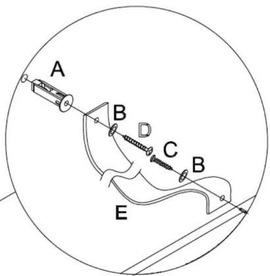
Important: Safety strap kit (part #15) must be installed to prevent tipping, damage and/or injury.
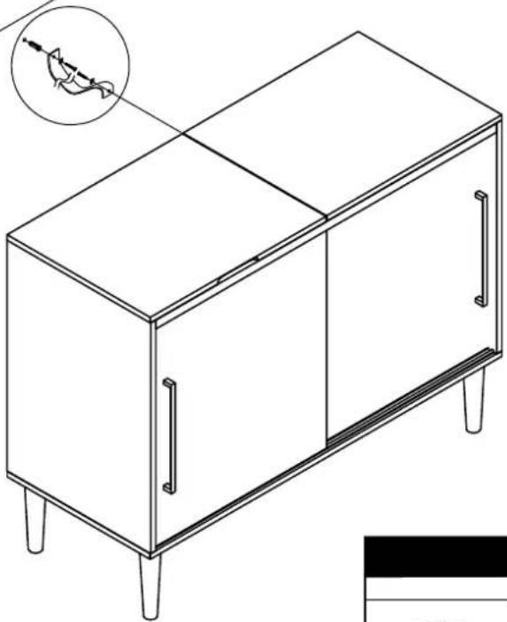
1) Insert short screw (C) through washer (B) and safety wall strap (E) and screw it into the top center of back panel (G).
2) Drill a 11/32" hole where you want to secure your unit. The hole should be at the same height as the hole in the top center of back panel (part G). Tap wall anchor (A) into the hole.
3) Insert long screw (D) through washer (B) and safety wall strap (E) into wall anchor (A).
Note: This item is not intended for clothing storage use.
Wall
natural_image
Line drawing of a cabinet with four legs and two doors, showing internal compartments and a magnified inset of the handle (no text or symbols)⚠ WARNING
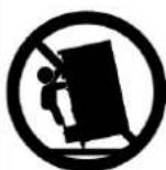
Children have died from furniture tipover. To reduce the risk of furniture tipover:
ALWAYS install tipover restraint provided. For use with televisions weighing 50lbs(23kg) or less. Use with heavier televisions may result in instability causing tip-over resulting in death or serious injury.
. NEVER allow children to stand, climb or hang on drawers, doors, or shelves.
. NEVER open more than one drawer at a time. Place heaviest items in the lowest drawers.
This is a permanent label. Do not remove!

Marque : Crosley
Modèle : Everett CF1103
Catégorie : Lecteur multimédia