QAD690010 - Multimètre Qian - Notice d'utilisation et mode d'emploi gratuit
Retrouvez gratuitement la notice de l'appareil QAD690010 Qian au format PDF.
| Caractéristique | Détails |
|---|---|
| Type d'appareil | Multimètre numérique |
| Plage de mesure de tension | 0-600V AC/DC |
| Plage de mesure de courant | 0-10A AC/DC |
| Plage de mesure de résistance | 0-20MΩ |
| Fonctions supplémentaires | Mesure de fréquence, test de diode, test de continuité |
| Affichage | Écran LCD avec rétroéclairage |
| Alimentation | Piles 9V |
| Dimensions | 150 x 75 x 35 mm |
| Poids | 300 g |
| Normes de sécurité | CAT III 600V |
| Utilisation | Idéal pour les travaux d'électricité, d'électronique et de dépannage |
| Maintenance | Vérifier régulièrement l'état des piles et des sondes |
| Garantie | 2 ans |
FOIRE AUX QUESTIONS - QAD690010 Qian
Questions des utilisateurs sur QAD690010 Qian
0 question sur cet appareil. Repondez a celles que vous connaissez ou posez la votre.
Poser une nouvelle question sur cet appareil
Téléchargez la notice de votre Multimètre au format PDF gratuitement ! Retrouvez votre notice QAD690010 - Qian et reprennez votre appareil électronique en main. Sur cette page sont publiés tous les documents nécessaires à l'utilisation de votre appareil QAD690010 de la marque Qian.
MODE D'EMPLOI QAD690010 Qian
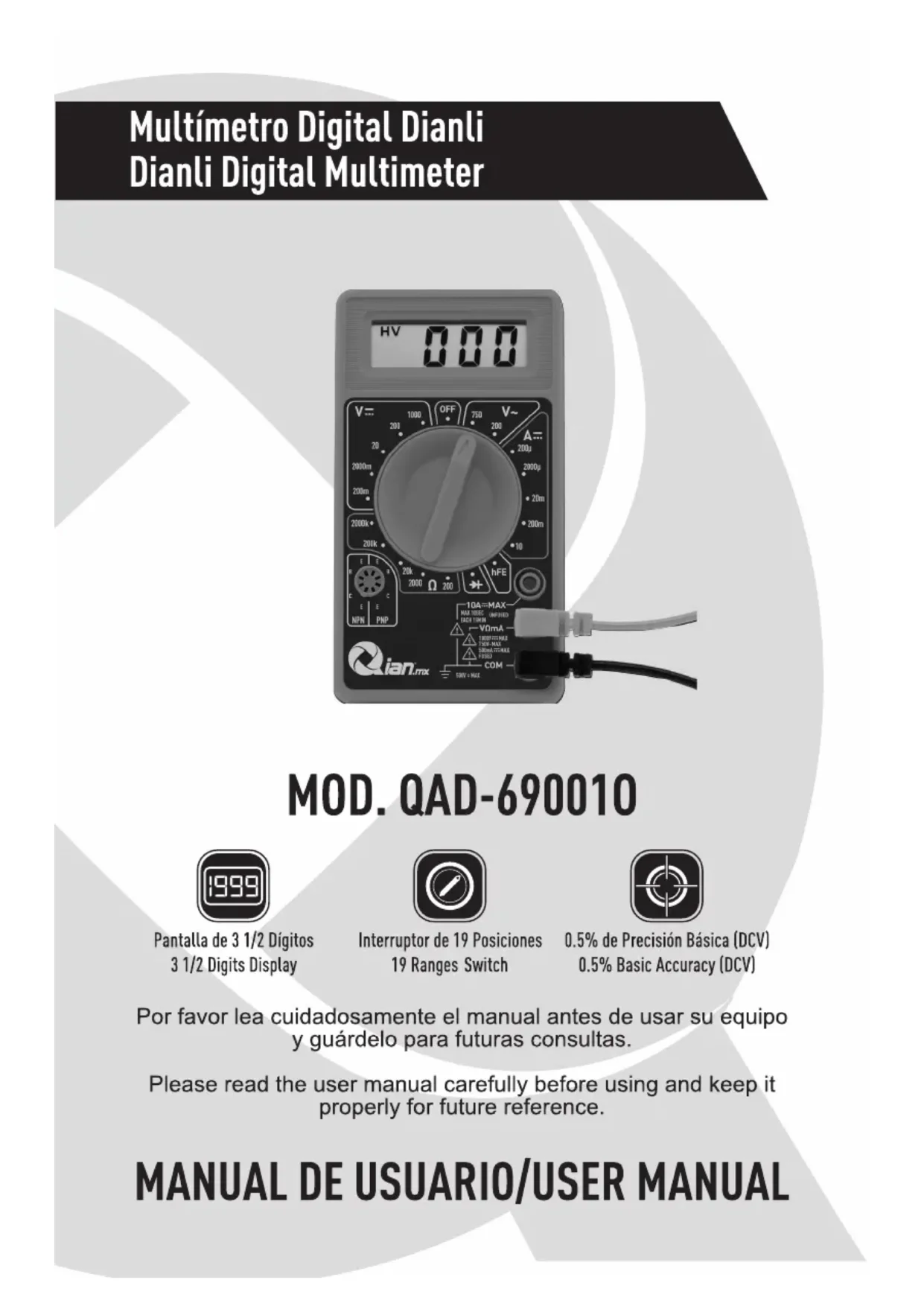
Multímetro Digital Dianli Dianli Digital Multimeter
text_image
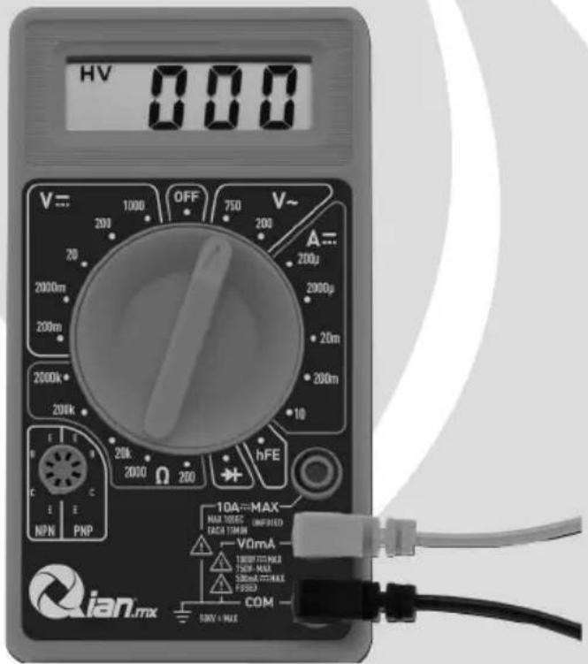
HV 000 V= 1000 OFF 750 V~ 200 200 200 2000m 2000μ 200m 20m 2000k 200m 200k 10 hFE 20k 200 hFE 2000 Ω 200 10A MAX MAX TOBSE UNIFIED FACI TIMIN V0mA 100V MAX 100V MAX COM NPN PNP Qian.mxMOD. QAD-690010

Pantalla de 3 1/2 Dígitos 3 1/2 Digits Display

Interruptor de 19 Posiciones 19 Ranges Switch

0.5% de Precisión Básica (DCV) 0.5% Basic Accuracy (DCV)
Por favor lea cuidadosamente el manual antes de usar su equipo y guárdelo para futuras consultas.
Please read the user manual carefully before using and keep it properly for future reference.
MANUAL DE USUARIO/USER MANUAL
Advertencia
Para evitar posibles descargas eléctricas o lesiones personales, y para evitar posibles daños al medidor o al equipo bajo prueba, respete las siguientes reglas:
»Inspeccione los cables de prueba en busca de aislamiento dañado o metal expuesto. Compruebe la continuidad de los cables de prueba.
»No aplique una tensión mayor que la nominal, como se indica en el medidor, entre los terminales o entre cualquier terminal y la conexión a tierra.
»El interruptor giratorio debe colocarse en la posición correcta y no se debe realizar ningún cambio de rango durante la medición para evitar daños en el medidor.
»Cuando el medidor funciona a un voltaje efectivo de más de 60 V en CC o 30 V rms en CA, se debe tener especial cuidado en caso de peligro de descarga eléctrica.
»Use los terminales, la función y el rango adecuados para sus mediciones.
»No utilice ni almacene el medidor en un entorno de alta temperatura, humedad, explosivo, inflamable y fuerte campo magnético. El rendimiento del medidor puede deteriorarse después de humedecido.
»Al usar los cables de prueba, mantenga los dedos detrás de los protectores para los dedos.
»Desconecte la alimentación del circuito y descargue todos los capacitores de alto voltaje antes de probar la resistencia, continuidad, diodos o hFE.
»Reemplace la batería tan pronto como aparezca el indicador de la batería. Con una batería baja, el medidor puede producir lecturas falsas que pueden provocar descargas eléctricas y lesiones personales.
»Retire la conexión entre los cables de prueba y el circuito que se está probando, y apague el medidor antes de abrir la caja del medidor.
»Al dar servicio al medidor, use solo el mismo número de modelo o partes de reemplazo de especificaciones eléctricas idénticas.
»El circuito interno del medidor no debe alterarse a voluntad para evitar daños al medidor y cualquier accidente.
»Se debe usar un paño suave y un detergente suave para limpiar la superficie del medidor durante el servicio. No se deben utilizar productos abrasivos ni disolventes para evitar que la superficie del medidor se corroa, dañe y se provoque un accidente.
»El medidor es adecuado para uso en interiores.
»Apague el medidor cuando no esté en uso y saque la batería cuando no la use por un tiempo prolongado. Revise constantemente la batería, ya que puede perder cuando se esté usando por algún tiempo, reemplace la batería tan pronto como aparezca una fuga. Una batería con fugas dañará el medidor.
Especificaciones Generales
Pantalla: LCD 3 ½ dígitos (cuenta 1999) 0.5" alto
Polaridad: Automático, indicado menos, asumido más.
Método de medida: Implemento doble interruptor A / D integral
Velocidad de muestreo: 2 veces por segundo.
Indicación de sobrecarga: se muestra "1"
Entorno operativo: 0°C \~ 40°C, a <80% RH
Ambiente de almacenamiento: -10°C \~ 50°C, a <85% de HR
Potencia: 9V NEDA 1604 o 6F22
Indicador de batería baja: "+- "
Electricidad estática: alrededor de 4mA
Tamaño del producto: 126 x 70 x 26 mm
Peso neto del producto: 108g (incluyendo batería
Especificaciones Técnicas
Las precisiones están garantizadas por 1 año, 23°C ± 5°C, menos del 80% de HR
VOLTAJE DC
| RANGO RESOLUCION EXACTIÓND | EXACTITUD | |
| 200mV 100uV ±(0.5% de rdg + 3D) | ±(0.5% de rdg + 3D) | |
| 2000mV 1mV | 1mV | ±(0.8% de rdg + 5D)20V 10mV |
| 20V | 10mV | |
| 200V 100mV | 100mV | |
| 1000V 1V ±(1.0% de rdg +15D) | ±(1.0% de rdg + 5D) | |
PROTECCIÓN CONTRA SOBRECARGAS: 220V rms CA para rango de 200mV y 1000V DC o 750V rms para todos los rangos.
VOLTAJE DE CORRIENTE ALTERNA
| RANGO RESOLUCIÓN EXACTIÓN | EXACTITUD |
| 200V 100mV | ± (2.0% de rdg +10D) |
| 750V 1V | 1V |
RESPUESTA: Respuesta promedio, calibrada en rms de una onda sinusoidal.
RANGO DE FRECUENCIA: 45Hz \~ 450Hz
PROTECCIÓN CONTRA SOBRECARGAS: 1000V DC o 750V rms para todos los rangos.
CONTINUIDAD AUDIBLE
| RANGO DESCRIPCIÓN | DESCRIPCIÓN |
| El altavoz incorporado suena si la resistencia es menor que 30±20Ω |
PROTECCIÓN CONTRA SOBRECARGA: 15 segundos como máximo 220 V rms.
CORRIENTE CONTINUA
| RANGO RESOLUCIONE EXACTIÓND | EXACTITUD | |
| 200uA 100nA | 100nA | ±(1.8% de rdg +2D)2000uA 1u |
| 2000uA | 1uA | |
| 20mA 10uA | 10uA | |
| 200mA 100uA ±(2.0% de rdg+2D) | ±(2.0% de rdg +2D) | |
| 10A 10mA ±(2.0% de rdg+10D) | ±(2.0% de rdg +10D) | |
PROTECCIÓN CONTRA SOBRECARGAS: fusible de 500mA 250V (rango 10A sin fusionar).
CAJA DE VOLTAJE DE MEDICIÓN: 200mV
RESISTENCIA
| RANGO RESOL | UCIÓN EXACTIÓND | EXACTITUD |
| 200Ω 0.1Ω | ± (1.0% de rdg +10D) | ± (1.0% de rdg +10D) |
| 2000Ω 1Ω | 1Ω | ± (1.0% de rdg +4D) |
| 20KΩ 10Ω | 10Ω | |
| 200KΩ 100Ω | 100Ω | |
| 2000KΩ 1KΩ | 1KΩ |
VOLTAJE MAXIMO DE CIRCUITO ABIERTO: 3.2V.
PROTECCIÓN CONTRA SOBRECARGA: 15 segundos como máximo 220Vrms
TEMPERATURA (CON SONDA K-TYPE)
| RANGO RESOL | UCIÓNESXACCIÓND | EXACTITUD |
| -40 °C a 150 °C | 1°C | ±(1.0% + 4)(hasta 150°C) |
| 150°C a 1370 °C ±(1.5% + 15)(desde | ±(1.5% + 15)(desde 150°C) |
PRUEBA DE BATERIA (1.5V, 9V)
| RANGO RESOLUCIONE EXACTIÓND | EXACTITUD | |
| 1.5V | 10 mV | 2KΩ |
| 9V 75Ω | 75Ω | |
INSTRUCCIONES DE OPERACIÓN
MEDICIÓN DE VOLTAJE DC & AC
Conecte la punta de prueba roja a la toma "VΩmA", la punta negra a la toma "COM".
Ajuste el interruptor de RANGO a la posición de VOLTAJE deseada, si el voltaje a medir no se conoce de antemano, coloque el interruptor en el rango más alto y redúzcalo hasta obtener una lectura satisfactoria.
Conecte los cables de prueba al dispositivo o circuito que se está midiendo.
Encienda la alimentación del dispositivo o del circuito que se está midiendo. El valor de voltaje aparecerá en la pantalla digital junto con la polaridad del voltaje.
MEDICIÓN DE CORRIENTE CONTINUA
Conductor rojo a "VΩmA". Cable negro a "COM" (para mediciones entre 200 mA y 10A, conecte el cable rojo a la toma "10A" con el botón completamente presionado).
RANGO cambia a la posición DCA deseada.
Abra el circuito que se va a medir y conecte los cables de prueba INSERIES con la carga con corriente para medir.
Lea el valor actual en la pantalla digital.
Además, la función "10A" está diseñada para uso intermitente solamente. El tiempo máximo de contacto de los cables de prueba con el circuito es de 15 segundos, con un tiempo de intervalo mínimo de segundos entre las pruebas.
MEDICIÓN DE LA RESISTENCIA
Conductor rojo a "VΩmA". Conductor negro a "COM".
RANGO cambiar a la posición OHM deseada.
Si la resistencia que se está midiendo está conectada a un circuito, apague la alimentación y descargue todos los condensadores antes de la medición.
Conecte los cables de prueba al circuito que se está midiendo.
Lea el valor de la resistencia en la pantalla digital.
MEDICIÓN DE DIODOS
Conductor rojo a "VΩmA", Conductor negro a "COM".
RANGO cambiar a la posición """.
Conecte la punta de prueba roja al ánodo del diodo que se va a medir y la punta de prueba negra al cátodo.
Se mostrará la caída de tensión directa en mV. Si se invierte el diodo, se mostrará la figura "1".
TRANSISTOR HFE MEDICIÓN
RANGO cambia a la posición hFE.
Determine si el transistor es de tipo PNP del tipo NPN y localice los cables del Emisor, la Base y el Colector. Inserte los cables en los orificios adecuados del zócalo hFE en el panel frontal.
El medidor mostrará el valor hFE aproximado en la condición de corriente de base 10μA y VCE2.8V.
Medición de la temperatura
El RANGO cambia a la posición TEMP, mostrará la temperatura ambiente en °C.
Conecte la pareja termoeléctrica tipo K a las tomas "VΩmA" y "COM".
La pantalla mostrará el valor de temperatura °C.
NOTA: El termopar tipo K máx. Temperatura de funcionamiento de la sonda: 250°C / 482°F (300°C / 572°F a corto plazo). El sensor suministrado con el instrumento es un termopar de talón desnudo de respuesta ultra rápida adecuado para muchas aplicaciones de uso general.
PRUEBA DE CONTINUIDAD AUDIBLE
Conductor rojo a "VΩmA", Conductor negro a "COM".
RANGO cambiar a la posición "».
Conecte los cables de prueba a dos puntos del circuito a probar. Si la resistencia es inferior a 30Ω ± 20Ω, sonará el zumbador.
USO DE LA SEÑAL DE PRUEBA
RANGO cambiar a la posición "」
Aparece una señal de prueba (50Hz) entre las tomas "VΩmA" y "COM", la tensión de salida es de aproximadamente 5V p-p con una impedancia de 50KΩ.
NOTA: PROTECCIÓN CONTRA SOBRECARGAS: 15 segundos como máximo 220Vrms.
PRUEBA DE BATERÍA
Ajuste el interruptor de FUNCIÓN a 9V o 1.5V.
Conecte el cable de prueba a la batería.
El valor de visualización es el voltaje.
REEMPLAZO DE BATERÍA Y FUSIBLES
Los fusibles rara vez necesitan reemplazo y se queman casi siempre como resultado del error del operador.
Si "☐☐" aparece en la pantalla, indica que la batería debe ser reemplazada.
Para reemplazar la batería y el fusible (500mA / 250V), retire los 2 tornillos en la parte inferior de la caja, simplemente retire los antiguos y reemplácelos por uno nuevo. Tenga cuidado de observar la polaridad.
Warning
To avoid possible electric shock or personal injury, and to avoid possible damage to the Meter or to the equipment under test, adhere to the following rules:
»Before using the Meter inspect the case. Do not use the Meter if it is damaged or the case (or part of the case) is removed. Look for
»cracks or missing plastic. Pay attention to the insulation around the connectors.
Inspect the test leads for damaged insulation or exposed metal.
»Check the test leads for continuity.
Do not apply more than the rated voltage, as marked on the Meter, between the terminals or between any terminal and grounding.
»The rotary switch should be placed in the right position and no any changeover of range shall be made during measurement is conducted to prevent damage of the Meter.
When the Meter working at an effective voltage over 60V in DC or 30V rms in AC, special care should be taken for there is danger of electric
»shock.
Use the proper terminals, function, and range for your measurements.
»Do not use or store the Meter in an environment of high temperature, humidity, explosive, inflammable and strong magnetic field. The performance of the Meter may deteriorate after dampened.
When using the test leads, keep your fingers behind the finger guards. Disconnect circuit power and discharge all high-voltage capacitors before testing resistance, continuity, diodes or hFE.
"Replace the battery as soon as the battery indicator appears. With a low battery, the Meter might produce false readings that can lead to electric shock and personal injury.
Remove the connection between the testing leads and the circuit being tested, and turn the Meter power off before opening the Meter case.
When servicing the Meter, use only the same model number or »identical electrical specifications replacement parts.
The internal circuit of the Meter shall not be altered at will to avoid >>damage of the Meter and any accident.
Soft cloth and mild detergent should be used to clean the surface of the Meter when servicing. No abrasive and solvent should be used to prevent the surface of the Meter from corrosion, damage and accident.
»The Meter is suitable for indoor use.
»Turn the Meter power off when it is not in use and take out the battery when not using for a long time. Constantly check the battery as it may leak when it has been using for some time, replace the battery as soon as leaking appears. A leaking battery will damage the Meter.
General Specifications
Max display: LCD 3 ½ digits (1999 count) 0.5" high
Polarity: Automatic, indicated minus, assumed plus.
Measure method: double integral A/D switch implement
Sampling speed: 2 times per second
Over-load indication: "1" is displayed
Operating Environment: 0°C\~40°C, at <80%RH
Storage Environment: -10°C\~50°C, at <85%RH
Power: 9V NEDA 1604 or 6F22
Low battery indication: "+-”
Static electricity: about 4mA
Product Size: 126 x 70 x 26mm
Product net weight: 108g (including battery)
Technical Specifications
Accuracies are guaranteed for 1 year, 23^ ± 5^ , less than 80% RH
DC VOLTAGE
| RANGE RESOLUTIONSACCURACY | ACCURACY | |
| 200mV 100uV ±(0.5% of rdg+3D) | ±(0.5% of rdg + 3D) | |
| 2000mV 1mV | 1mV | ±(0.8% of rdg + 5D)20V 10mV |
| 20V | 10mV | |
| 200V 100mV | 100mV | |
| 1000V 1V ±(1.0% of rdg + 5D) | ±(1.0% of rdg + 5D) | |
OVERLOAD PROTECTION: 220V rms AC for 200mV range and 1000V DC or 750V rms for all ranges.
AC VOLTAGE
RESPONSE: Average responding, calibrated in rms of a sine wave.
| RANGE RESOLUTIOREACCURACY | ACCURACY | |
| 200V 100mV | 100mV | ±(2.0% of rdg +10D) |
| 750V 1V | 1V | |
FREQUENCY RANGE: 45Hz \~ 450Hz
OVERLOAD PROTECTION: 1000V DC or 750V rms for all ranges.
AUDIBLE CONTINUITY
OVERLOAD PROTECTION: 15 second maximum 220 V rms.
| RANGE DESCRIPTION | DESCRIPTION |
| Built-in speaker sounds if resistance is less then 30±20Ω |
DC CURRENT
| RANGE RESOLUTIONSACCURACY | ACCURACY | |
| 200uA 100nA | 100nA | ±(1.8% of rdg +2D)2000uA 1u |
| 2000uA | 1uA | |
| 20mA 10uA | 10uA | |
| 200mA 100uA ±(2.0% of rdg+2D) | ±(2.0% of rdg +2D) | |
| 10A 10mA ±(2.0% of rdg+10D) | ±(2.0% of rdg +10D) | |
OVERLOAD PROTECTION: 500mA 250V fuse (10A range unfused).
MEASURING VOLTAGE DROP: 200mV
RESISTANCE
| RANGE RESOLUTIOREACCURACY | ACCURACY | ||
| 200Ω 0.1Ω | ±(1.0% of rdg+10D) | ±(1.0% of rdg +10D) | |
| 2000Ω 1Ω | 1Ω | ±(1.0% of rdg +4D) | |
| 20KΩ 10Ω | 10Ω | ||
| 200KΩ 100Ω | 100Ω | ||
| 2000KΩ 1KΩ | 1KΩ | ||
MAXIMUM OPEN CIRCUIT VOLTAGE: 3.2V.
OVERLOAD PROTECTION: 15 seconds maxi-mum 220Vrms
TEMPERATURE (WITH K-TYPE PROBE)
| RANGE RESOLUTIONSACCURACY | ACCURACY | |
| -40 °C TO 150 °C | 1°C±(1.5% + 15)(over | ±(1.0% + 4)(up to 150°C) |
| 150°C to 1370 °C | ±(1.5% + 15)(over 150°C) | |
BATTERY TEST (1.5V, 9V)
| RANGE RESOLUTIONSACCURACY | ACCURACY | |
| 1.5V | 10 mV | 2KΩ |
| 9V 75Ω | 75Ω | |
OPERATING INSTRUCTIONS
DC & AC VOLTAGE MEASUREMENT
Connect red test lead to "VΩmA" jack, Black lead to "COM" jack. Set RANGE switch to desired VOLTAGE position, if the voltage to be measured is not known beforehand, set switch to the highest range and reduce it until satisfactory reading is obtained.
Connect test leads to device or circuit being measured.
Turn on power of the device or circuit being measured voltage value will appear on Digital Display along with the voltage polarity.
DC CURRENT MEASUREMENT
Red lead to "VΩmA". Black lead to "COM" (for measurements between 200mA and 10A connect red lead to "10A" jack with fully depressed.) RANGE switch to desired DCA position.
Open the circuit to be measured, and connect test leads INSERIES with the load in with current is to measure.
Read current value on Digital Display.
Additionally, "10A" function is designed for intermittent use only.
Maximum contact time of the test leads with the circuit is 15 seconds, with a minimum intermission time of seconds between tests.
RESISTANCE MEASUREMENT
Red lead to "VΩmA". Black lead to "COM".
RANGE switch to desired OHM position.
If the resistance being measured is connected to a circuit, turn off power and discharge all capacitors before measurement.
Connect test leads to circuit being measured.
Read resistance value on Digital Display.
DIODE MEASUREMENT
Red lead to "VΩmA", Black lead to "COM".
RANGE switch to " " position.
Connect the red test lead to the anode of the diode to be measured and black test lead to cathode.
The forward voltage drop in mV will be displayed. If the diode is reversed, figure "1" will be shown.
TRANSISTOR hFE MEASUREMENT
RANGE switch to the hFE position.
Determine whether the transistor is PNP of NPN type and locate the Emitter, Base and Collector leads. Insert the leads into the proper holes of the hFE Socket on the front panel.
The meter will display the approximate hFE value at the condition of base current 10μA and VCE2.8V.
TEMPERATURE MEASUREMENT
RANGE switch to TEMP position, it will display room temperature in °C value.
Connect the K-type thermoelectric couple to "VΩmA" and "COM" jacks. The display will read Temperature value °C.
NOTE: The K-type thermocouple Max. Operating temperature of Probe: 250^ C/482°F ( 300^ C/572°F short-term). The sensor supplied with the instrument is an ultra fast response naked bead thermocouple suitable for many general purpose applications.
AUDIBLE CONTINUITY TEST
Red lead to "VΩmA", Black lead to "COM".
RANGE switch to “•” position.
Connect test leads to two points of circuit to be tested. If the resistance is lower then 30 ± 20 , the buzzer will sound.
TEST SIGNAL USE
RANGE switch to "☐" position.
A test signal (50Hz) appears between "VΩmA" and "COM" jack, the output voltage is approx 5V p-p with 50KΩ impedance.
NOTE: OVERLOAD PROTECTION: 15 seconds maximum 220Vrms.
BATTERY TEST
Set the FUNCTION switch to 9V or 1.5V.
Connect the test lead to Battery.
The display value is voltage.
BATTERY AND FUSE REPLACEMENT
Fuse rarely need replacement and blow almost always as a result of operator error.
If “☐” appears in display, it indicates that the battery should be replaced. To replace battery & Fuse (500mA/250V) remove the 2 screws in the bottom of the case, simply remove the old, and replace with a new one. Be careful to observe polarity.
Póliza de Garantía
Qian S.A. de C.V., garantizará este producto en todos sus componentes y mano de obra durante el periodo de 12 meses, contando a partir de la fecha de adquisición contra cualquier defecto de fabricación y funcionamiento durante el uso normal y doméstico de este producto.
Qian S.A. de C.V. garantiza al comprador la ausencia de anomalías de fabricación y funcionamiento incluyendo piezas y componentes del producto o en lo referente a materiales.
- Esta póliza ampara únicamente productos comercializados por Qian S.A. de C.V., a través de sus distribuidores autorizados dentro de la República Mexicana y los Estados Unidos de América.
- Para la validación de ésta se deberá presentar el producto defectuoso junto con la presente póliza de garantía completamente llenada y sellada por el distribuidor que realizó la venta o la factura, recibo, o comprobante de compra en el lugar donde se aquirió el producto, o en el Centro de Servicio Nacional.
| Producto: | Sello del Distribuidor |
| Fecha de Compra: | |
| Modelo: | |
| Marca: Qian.mx |
-
Qian S.A. de C.V. podrá utilizar piezas nuevas, restauradas o usadas en buenas condiciones para reparar o reemplazar cualquier producto, sin costo adicional para el consumidor, siempre y cuando el periodo de garantía estipulado en la presente póliza no se haya terminado.
-
En caso de que el producto no tenga reparación, se generará el cambio por un producto similar o de características superiores.
-
El tiempo de reparación no será mayor de 30 días naturales a partir de la fecha de recepción del producto por parte de Qian S.A. de C.V. o en su Centro de Servicio Autorizado.
-
Qian S.A. de C.V. cubrirá los gastos de envío requeridos para la presentación del producto dentro de la red de centros de servicio autorizados.
Exclusions:
Qian S.A. de C.V. no hará valida esta póliza de garantía en los siguientes casos:
- Cuando el producto se hubiese utilizado en condiciones distintas a las normales.
- Cuando el producto no se hubiese operado de acuerdo al instructivo de uso que lo acompaña.
- Cuando el producto hubiese sido alterado o reparado por personas no autorizadas por parte de Qian S.A. de C.V.
Para hacer válida la garantía, así como la adquisición de componentes, partes consumibles y accesorios pueden solicitar información en www.qian.mx o dirigirse a cualquier Centro de Servicio Autorizado Qian S.A. de C.V.
Centro de Servicio Autorizado para Garantía:
Qian S.A. de C. V.
Calz. José Guadalupe Gallo #8490-A
Col. Agua Blanca Industrial, Zapopan
Jalisco, México. C.P. 45235
Tel. +52.33.1078.3404
Centro de Servicio Autorizado para Componentes,
Consumibles y Accesorios:
Qian S.A. de C. V.
Calz. José Guadalupe Gallo #8490-A
Col. Agua Blanca Industrial, Zapopan
Jalisco, México. C.P. 45235
Tel. +52.33.1078.3404
Warranty Policy
Qian S.A. de C.V., will warranty this product in all its parts and workmanship for the period of 12 months, counting from the date of purchase against defects in manufacture and operation during normal and domestic use of this product.
Qian S.A. de C.V. warranty the buyer the absence of manufacturing and operation anomalies including parts and components of the product or in relation to materials.
- This policy covers only products marketed by Qian S.A. de C.V., through its authorized distributors within the Mexican Republic and United States of America.
- For the validation of this, the defective product must be presented together with this warranty policy completely filled out and stamped by the distributor that made the sale or the invoice, receipt, or proof of purchase in the place where the product was purchased, or in the National Service Center.
| Product: | Distributor Seal |
| Date of Purchase: | |
| Model: | |
| Brand: Qian.mx |
-
Qian S.A. de C.V. may use new parts, refurbished or used in good condition to repair or replace any product at no additional cost to the consumer, as long as the warranty period specified in this policy has not been completed.
-
If the product does not have repair, change a similar product or superior characteristics is generated.
-
The repair time will not exceed 30 calendar days from the date of receipt of the product by Qian S.A. de C.V. or its Authorized Service Center.
-
Qian S.A. de C.V. will cover shipping costs required for presentation of the product within the network of authorized service centers.
Exclusions:
Qian S.A. de C.V. will not validate this warranty policy in the following cases:
- When the product has been used under normal conditions..
- When the product had not operated according to the instructions of use that accompanies it.
- When the product has been altered or repaired by unauthorized persons by Qian S.A. de C.V.
For warranty purposes, as well as procurement of components, consumable parts and accessories www.qian.mx can request information or contact any Authorized Service Center Qian S.A. de C.V.
Centro de Servicio Autorizado para Garantía: Qian S.A. de C. V.
Calz. José Guadalupe Gallo #8490-A
Col. Agua Blanca Industrial, Zapopan
Jalisco, México. C.P. 45235
Tel. +52.33.1078.3404
Centro de Servicio Autorizado para Componentes, Consumibles y Accesorios:
Qian S.A. de C. V.
Calz. José Guadalupe Gallo #8490-A
Col. Agua Blanca Industrial, Zapopan
Jalisco, México. C.P. 45235
Tel. +52.33.1078.3404