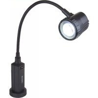
LightFlex LF10 - Lampe Carson - Notice d'utilisation et mode d'emploi gratuit
Retrouvez gratuitement la notice de l'appareil LightFlex LF10 Carson au format PDF.


| Type de produit | Lampe de travail |
| Marque | Carson |
| Modèle | LightFlex LF10 |
| Alimentation | Secteur (adaptateur inclus) ou piles |
| Type de piles | 4 piles AA 1,5 V |
| Fixation | Aimant intégré dans la base ou pince de table incluse |
| Source lumineuse | LED |
| Interrupteur | Sur le devant de la base |
| Pince de table | Incluse, se fixe solidement |
| Base de loupe | Avec aimant intégré pour fixation sur surfaces métalliques |
| Adaptateur secteur | Inclus, se branche sur la gauche de la base |
| Commutation automatique | Passage automatique sur piles lorsque l'adaptateur est débranché |
| Sécurité | Ne pas regarder directement la LED pour éviter les lésions oculaires |
| Entretien | Changer les piles en retirant le couvercle et le boîtier à piles |
| Poids | Environ 500 g (estimation) |
| Dimensions | Environ 20 x 10 x 5 cm (estimation) |
FOIRE AUX QUESTIONS - LightFlex LF10 Carson
Questions des utilisateurs sur LightFlex LF10 Carson
0 question sur cet appareil. Repondez a celles que vous connaissez ou posez la votre.
Poser une nouvelle question sur cet appareil
Téléchargez la notice de votre Lampe au format PDF gratuitement ! Retrouvez votre notice LightFlex LF10 - Carson et reprennez votre appareil électronique en main. Sur cette page sont publiés tous les documents nécessaires à l'utilisation de votre appareil LightFlex LF10 de la marque Carson.
MODE D'EMPLOI LightFlex LF10 Carson
CARSON PRO®
LIGHTFLEX™ LF-10
Instructions for Use:
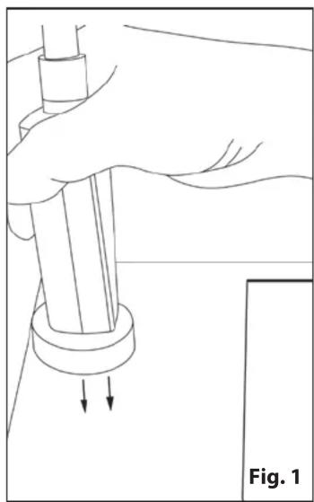
- Attach task lamp to flat metal surface using built-in magnet located in magnifier base (Fig. 1).
- To use with table clamp, attach clamp to table and tighten securely (Fig 2). Attach task lamp to top portion of clamp using built-in magnet located in magnifier base (Fig. 3).
- Plug in power adapter to standard wall outlet and insert plug into power jack located on the left side of the magnifier base (Fig. 4).
• To use with battery power, remove the plug from the power jack. The unit will automatically switch to battery power. - Position task lamp head as desired. Turn on light using switch located on the front of the task lamp base (Fig. 5).
To change batteries:
- Remove battery door and then remove battery case from compartment (Fig. 6-7).
- Replace exhausted batteries with 4 fresh AA 1.5V batteries according to polarity indicators printed inside case.
- Place loaded battery case into battery compartment with metal contacts facing upwards and towards the inside of the battery compartment (Fig. 8).
- Replace battery door when finished.
Caution: Do not look at the LED light directly to avoid harming your eyes.
natural_image
Line drawing of a hand holding a cylindrical object with two arrows indicating downward motion, labeled 'Fig. 1' (no text or symbols on the diagram itself)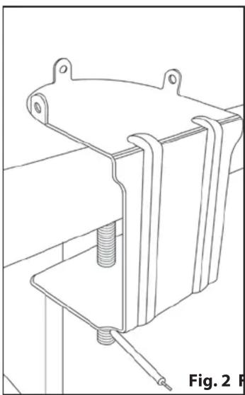
natural_image
Technical line drawing of a mechanical clamp or bracket assembly (no text or symbols)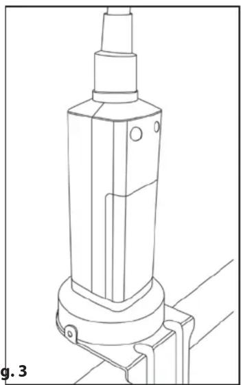
natural_image
Technical line drawing of a mechanical component with no visible text or symbols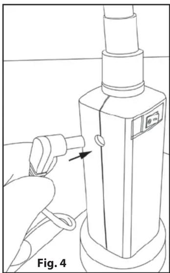
natural_image
Line drawing of a handheld device with a hand operating it, labeled Fig. 4 (no text or symbols on the device itself)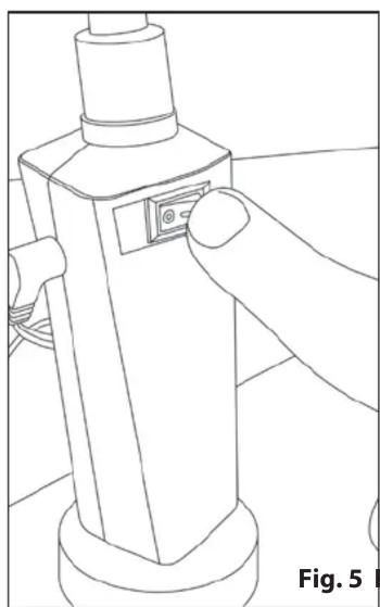
natural_image
Line drawing of a mechanical device with a finger interacting with the button (no text or symbols)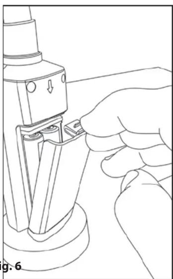
natural_image
Line drawing of a hand operating a mechanical device with a base, showing no text or symbols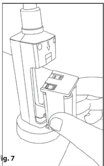
natural_image
Line drawing of a hand operating a mechanical device with a handle and control panel (no text or symbols)
natural_image
Line drawing of hands assembling or adjusting a mechanical component, labeled 'Fig. 8' (no text or symbols on the diagram itself)Marque : Carson
Modèle : LightFlex LF10
Catégorie : Lampe