
PCD26178N - Réfrigérateur Pelgrim - Notice d'utilisation et mode d'emploi gratuit
Retrouvez gratuitement la notice de l'appareil PCD26178N Pelgrim au format PDF.

| Marque | Pelgrim |
| Modèle | PCD26178N |
| Type de produit | Réfrigérateur encastrable |
| Dimensions (H x L x P) | 1775-1780 x 540 x 555 mm |
| Volume total approximatif | 350 L |
| Classe climatique | ST (subtropical) |
| Classe énergétique | E (estimation) |
| Consommation annuelle estimée | 250 kWh |
| Niveau sonore | 40 dB (estimation) |
| Nombre de clayettes | 4 clayettes en verre |
| Nombre de bacs à légumes | 1 bac à légumes |
| Éclairage intérieur | LED |
| Type de dégivrage | Automatique (No Frost) |
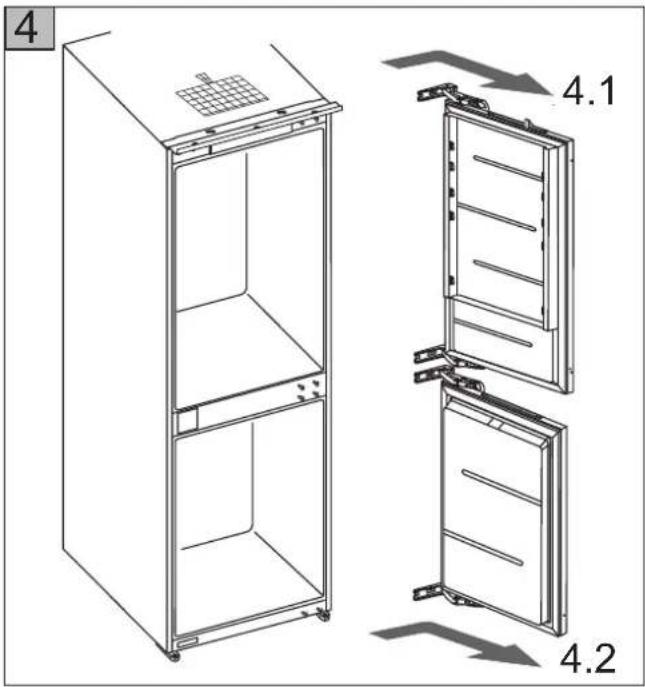
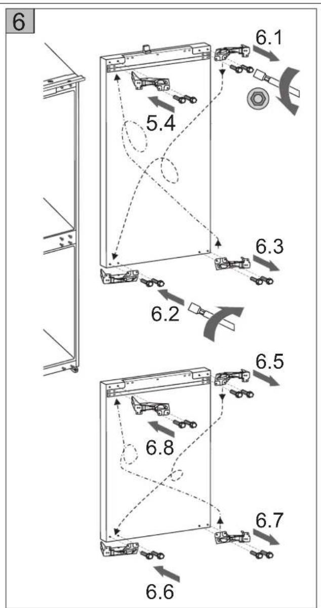
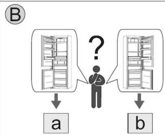
| Réversibilité des portes | Oui |
| Réfrigérant | R600a (isobutane) |
| Poids net | 65 kg (estimation) |
| Tension / Fréquence | 220-240 V / 50 Hz |
| Puissance électrique | 120 W (estimation) |
| Entretien et nettoyage | Nettoyer avec un chiffon doux et de l'eau savonneuse |
| Sécurité | Verrouillage enfant (optionnel), alerte porte ouverte |
| Pièces détachées et réparabilité | Disponibles via le service après-vente Pelgrim |
FOIRE AUX QUESTIONS - PCD26178N Pelgrim
Questions des utilisateurs sur PCD26178N Pelgrim
0 question sur cet appareil. Repondez a celles que vous connaissez ou posez la votre.
Poser une nouvelle question sur cet appareil
Téléchargez la notice de votre Réfrigérateur au format PDF gratuitement ! Retrouvez votre notice PCD26178N - Pelgrim et reprennez votre appareil électronique en main. Sur cette page sont publiés tous les documents nécessaires à l'utilisation de votre appareil PCD26178N de la marque Pelgrim.
MODE D'EMPLOI PCD26178N Pelgrim
EN
DE
FR
NL
IT
ES
NO
DA
SE
FI
CZ
SK
SI
HR
SR
RU
UA
KZ
ZH/CN
ZH/HK
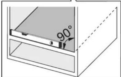
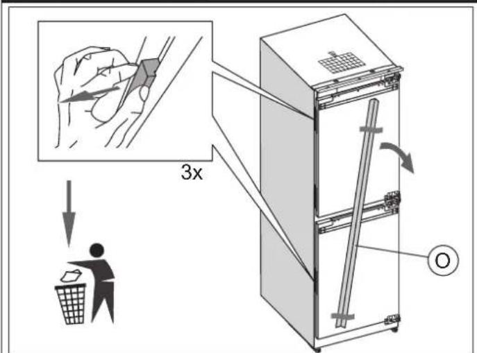
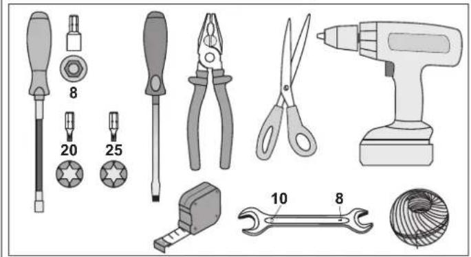
MOUNTING INSTRUCTIONS
EINBAUANWEISUNG
NOTICE D'INSTALLATION
INBOUW-HANDLEIDING
INSTRUZIONI PER L'INSTALLAZIONE
INSTRUCCIONES PARA EMPOTRAR
MONTERINGSANVISNING
MONTERERINGSANVISNING
MONTERINGSANVISNING
ASENNUSOHJE
NÁVOD K VESTAVĚNÍ
NÁVOD PRE ZABUDOVANIE
NAVODILA ZA VGRADNJO
UPUTE ZA UGRADNJU
UPUTSTVA ZA UGRADNJU
РУКОВОДСТВО ПО МОНТАЖУ
ІНСТРУКЦІЯ ДЛЯ МОНТУВАННЯ
ОРНАТУ ЖОННДЕГІ НУСКАУЛЫК
嵌入安装说明
嵌入安裝說明

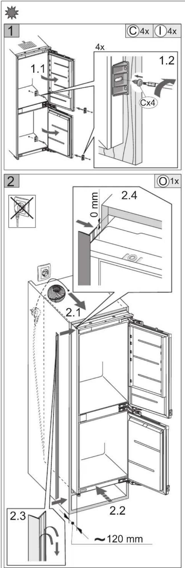
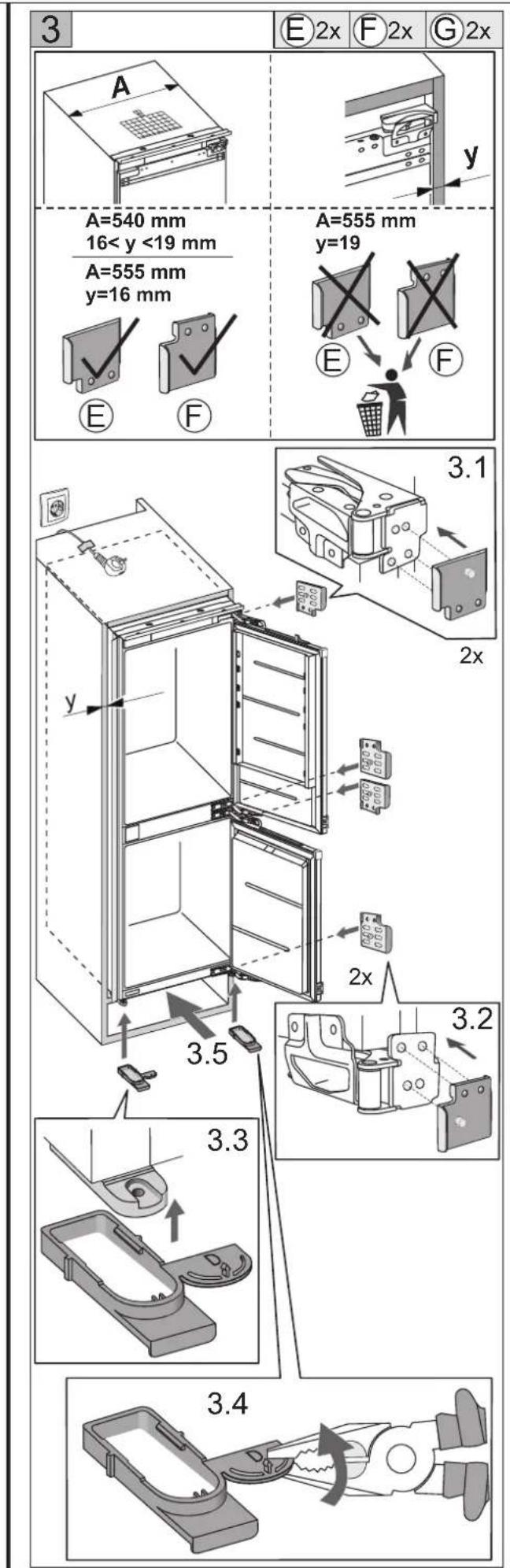
| A (mm) | B (mm) | C (mm) |
| 540 | 1772 | 1775-1780 |
| 555 | 1772 | 1775-1780 |

natural_image
Illustration of various screwdriver and tool components including screwdriver, pliers, power drill, and wire coil (no text or labels)
natural_image
Technical illustration of a mechanical component with three views (E, F, G) showing internal structure and mounting base (no text or symbols)
natural_image
Four 3D mechanical part diagrams labeled K, L, and M, showing different structural configurations (no text or symbols beyond labels)
natural_image
Two technical diagrams showing a rectangular component with a 3x x ratio and a 1x x ratio, no text or symbols present.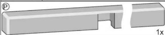
natural_image
3D diagram of a rectangular mechanical part with an open slot and a separate cut section, labeled '1x' (no text or symbols on the object itself)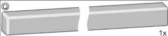
natural_image
Two 3D rectangular blocks with a small circular symbol on top-left, one cut to form a wedge, the other flat (no text or symbols)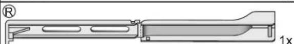
natural_image
Technical line drawing of a mechanical component with no visible text or symbols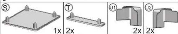
natural_image
Four 3D mechanical part diagrams labeled S, T, U1, U2 with dimension annotations (1x, 2x) — no readable text or symbols beyond labels.
flowchart
graph TD
    A["A"] -->|↓| B["A"]
    B -->|?| C["B"]
    C -->|↓| D["B"]
A

flowchart
graph TD
    A["Person"] --> B["a"]
    A --> C["b"]
    D["Question mark"] --> E["?"]
    style D fill:#f9f,stroke:#333
natural_image
Mechanical assembly diagram showing a piston-cranked joint and connecting rod components (no text or labels)flowchart
graph TD
    subgraph_D["Structure"]
        A1["a= b=c"] --> B1["a= b=c"]
        B1 --> C1["c"]
        C1 --> D1["a= b=c"]
    end
    subgraph_E1["Structure"]
        A2["a≠b≠c"] --> B2["a≠b≠c"]
        B2 --> C2["c"]
        C2 --> D2["a= b=c"]
    end
    subgraph_E2["Structure"]
        A3["a≠b≠c"] --> B3["a≠b≠c"]
        B3 --> C3["c"]
        C3 --> D3["a= b=c"]
    end
    style D fill:#f9f,stroke:#333
    style E1 fill:#ccf,stroke:#333
    style E2 fill:#ccf,stroke:#333
natural_image
Mechanical assembly diagram showing a lever mechanism with no visible text or symbolsnatural_image
Mechanical linkage diagram showing a lever mechanism with motion arrows (no text or symbols)natural_image
Technical line drawing of a mechanical bracket assembly (no text or symbols)natural_image
Technical line drawing of a mechanical bracket assembly (no text or symbols)natural_image
Mechanical assembly diagram showing a bracket with mounting holes and a curved arrow indicating motion (no text or symbols)natural_image
Pure mechanical assembly diagram showing a lever and bracket without any text, numbers, or symbolsflowchart
graph LR
    A["Person confused"] --> B["Truck in table with a question mark"]
    B --> C["Truck in trash bin with a checkmark"]


Marque : Pelgrim
Modèle : PCD26178N
Catégorie : Réfrigérateur