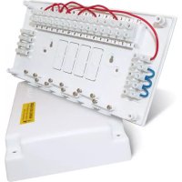
TC100 - Maison intelligente Salus - Notice d'utilisation et mode d'emploi gratuit
Retrouvez gratuitement la notice de l'appareil TC100 Salus au format PDF.

| Type de produit | Centrale de câblage pour système de chauffage central |
| Marque | Salus |
| Modèle | TC100 |
| Catégorie | Maison intelligente |
| Alimentation | 230 V AC, protégé par fusible 5 A |
| Fonctions principales | Simplification du câblage et vérification des circuits ; compatible avec les systèmes 2 zones à vannes motorisées (S Plan) et 3 zones (Y Plan) ; bornes de grande taille, points d'accès aux câbles et serre-câbles |
| Compatibilité | Thermostats d'ambiance Salus RT200/RT300/RT500, thermostat de cylindre CT100, programmateur EP200, vannes motorisées MV222/MV228/MV322/MV328, thermostat antigel FT100 |
| Entretien et nettoyage | Nettoyer avec un chiffon sec et non abrasif. Ne pas utiliser de produits chimiques. |
| Sécurité | Installation conforme aux normes IEE (BS 7671:2001) par un installateur qualifié. Débrancher l'alimentation avant toute intervention. |
| Dimensions | Environ 200 x 150 x 50 mm |
| Poids | Environ 300 g |
FOIRE AUX QUESTIONS - TC100 Salus
Questions des utilisateurs sur TC100 Salus
0 question sur cet appareil. Repondez a celles que vous connaissez ou posez la votre.
Poser une nouvelle question sur cet appareil
Téléchargez la notice de votre Maison intelligente au format PDF gratuitement ! Retrouvez votre notice TC100 - Salus et reprennez votre appareil électronique en main. Sur cette page sont publiés tous les documents nécessaires à l'utilisation de votre appareil TC100 de la marque Salus.
MODE D'EMPLOI TC100 Salus
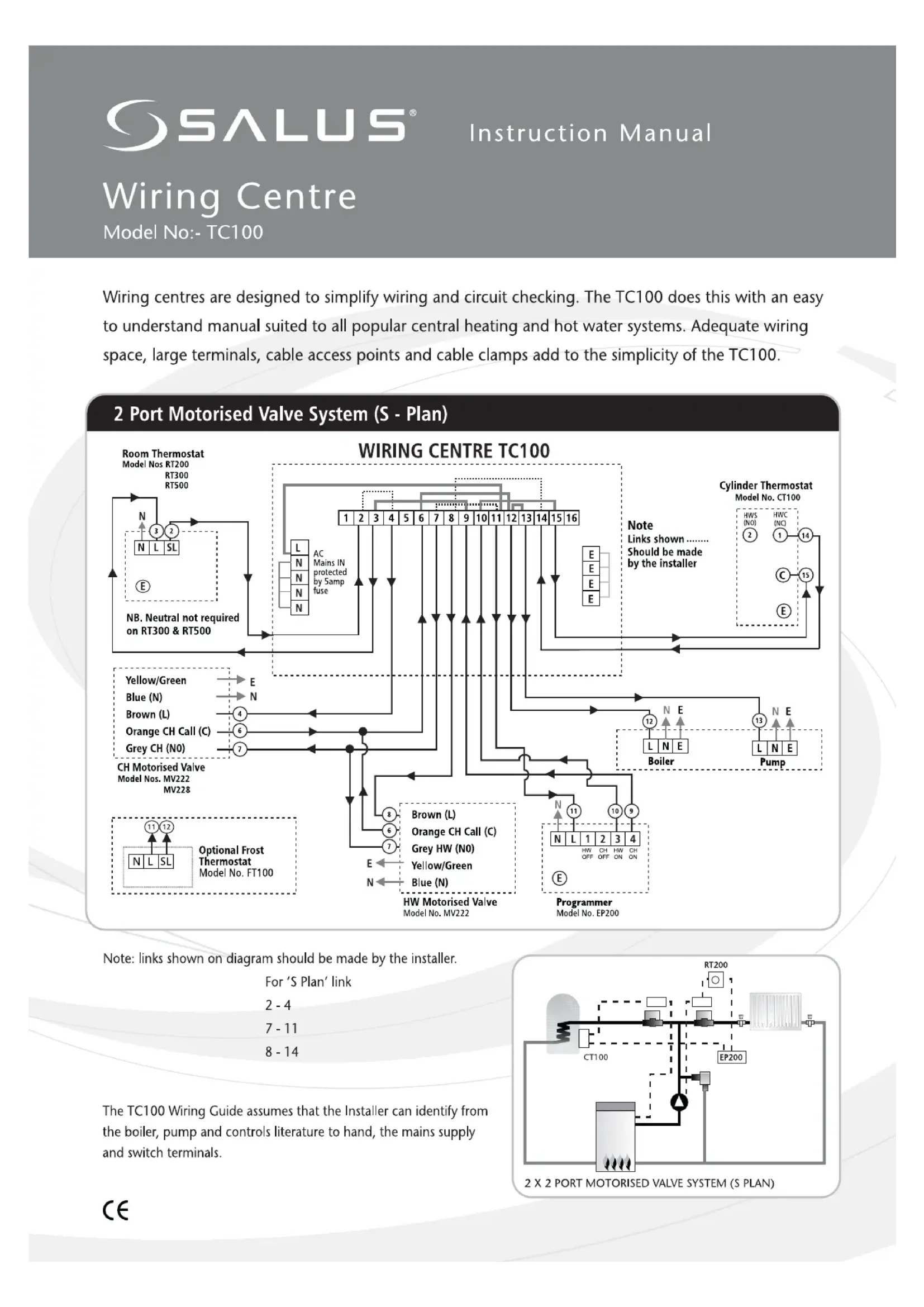
Wiring centres are designed to simplify wiring and circuit checking. The TC100 does this with an easy to understand manual suited to all popular central heating and hot water systems. Adequate wiring space, large terminals, cable access points and cable clamps add to the simplicity of the TC100.
2 Port Motorised Valve System (S - Plan)
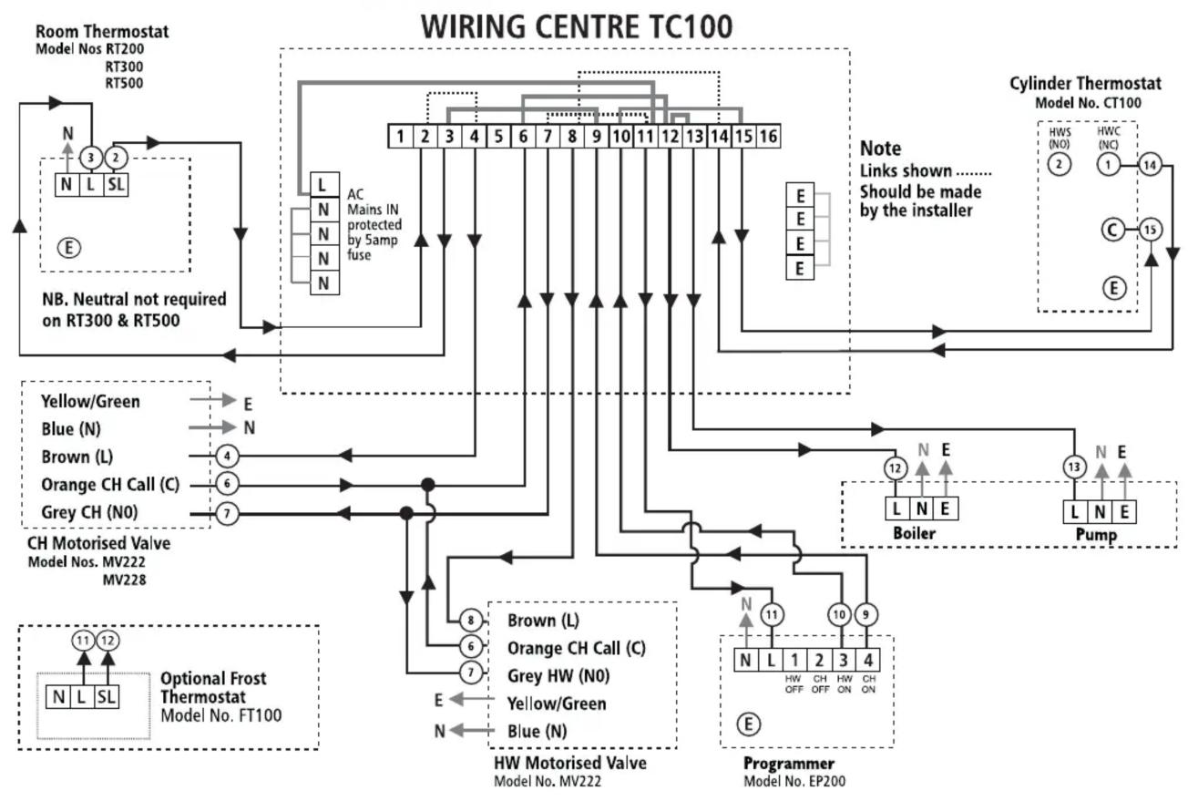
flowchart
graph TD
    A["Room Thermostat\nModel Nos RT200\nRT300\nRT500"] --> B["N ③ ② N L SL"]
    B --> C["AC Mains IN protected by Samp fuse"]
    C --> D["1 2 3 4 5 6 7 8 9 10 11 12 13 14 15 16"]
    D --> E["Yellow/Green"]
    D --> F["Blue (N)"]
    D --> G["Brown (L)"]
    D --> H["Orange CH Call (C)"]
    D --> I["Grey CH (N0)"]
    E --> J["E"]
    F --> K["E"]
    G --> L["E"]
    H --> M["E"]
    I --> N["E"]
    J --> O["Note: Links shown ...... Should be made by the installer"]
    K --> O
    L --> O
    M --> O
    N --> O
    O --> P["Cylinder Thermostat\nModel No. CT100"]
    P --> Q["HWS (NO) ②"]
    P --> R["HWC (NC) ①"]
    P --> S["C ⑮"]
    P --> T["Pump"]
    U["CH Motorised Valve\nModel Nos. MV222\nMV228"] --> V["Optional Frost Thermostat\nModel No. FT100"]
    V --> W["N ⑪ ⑫ N L SL"]
    V --> X["L ⑬ N SL"]
    Y["HW Motorised Valve\nModel No. MV222"] --> Z["Programmer\nModel No. EP200"]
    Z --> AA["N ⑭ N L ⑮"]
    Z --> AB["ORANGE CH Call (C)"]
    Z --> AC["GREY HW (N0)"]
    Z --> AD["YELLOW/GREEN"]
    Z --> AE["BLUE (N)"]
    AA --> AF["HW OFF ON"]
    AB --> AG["HW OFF ON"]
    AC --> AH["HW OFF ON"]
    AD --> AI["HW OFF ON"]
    AE --> AJ["HW OFF ON"]
    AF --> AK["HW OFF ON"]
    AG --> AL["HW OFF ON"]
    AH --> AM["HW OFF ON"]
    AI --> AN["HW OFF ON"]
    AJ --> AO["HW OFF ON"]
    AK --> AP["HW OFF ON"]
    AL --> AQ["HW OFF ON"]
    AM --> AR["HW OFF ON"]
    AN --> AS["HW OFF ON"]
Note: links shown on diagram should be made by the installer.
For 'S Plan' link
2 - 4
7 - 11
8 - 14
The TC100 Wiring Guide assumes that the Installer can identify from the boiler, pump and controls literature to hand, the mains supply and switch terminals.
flowchart
graph TD
    A["CT100"] --> B["Valve"]
    B --> C["Control Unit"]
    C --> D["RT200"]
    D --> E["Sensor"]
    E --> F["Control Unit"]
    F --> G["EP200"]
    G --> H["Valve"]
    H --> I["Control Unit"]
    I --> J["Control Unit"]
    J --> K["Control Unit"]
    K --> L["Control Unit"]
    L --> M["Control Unit"]
    M --> N["Control Unit"]
    N --> O["Control Unit"]
    O --> P["Control Unit"]
    P --> Q["Control Unit"]
    Q --> R["Control Unit"]
    R --> S["Control Unit"]
    S --> T["Control Unit"]
    T --> U["Control Unit"]
    U --> V["Control Unit"]
    V --> W["Control Unit"]
    W --> X["Control Unit"]
    X --> Y["Control Unit"]
    Y --> Z["Control Unit"]
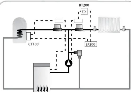
2 X 2 PORT MOTORISED VALVE SYSTEM (S PLAN)
3 Port Motorised Valve System (Y - Plan)
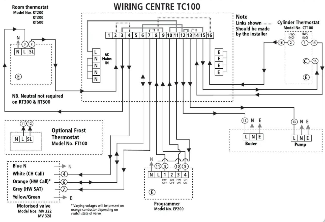
flowchart
graph TD
    A["Room thermostat\nModel Nos RT200\nRT300\nRT500"] --> B["N L SL"]
    B --> C["AC Mains IN"]
    C --> D["1 2 3 4 5 6 7 8 9 10 11 12 13 14 15 16"]
    D --> E["E E E"]
    E --> F["Cylinder Thermostat\nModel No. CT100\nHWS (NO)\nHWC (NC)\n1 14\nC\nE"]
    F --> G["Boiler"]
    F --> H["Pump"]
    I["Optional Frost Thermostat\nModel No. FT100"] --> J["Blue N\nWhite (CH Call)\nOrange (HW Call)*\nGrey (HW SAT)\nYellow/Green"]
    J --> K["Motorised valve\nModel Nos. MV 322\nMV 328"]
    K --> L["Blue N\nWhite (CH Call)\nOrange (HW Call)*\nGrey (HW SAT)\nYellow/Green"]
    L --> M["Programmer\nModel No. EP200"]
    M --> N["N L 1 2 3 4\nN HW OFF ON ON ON"]
    M --> O["N L 1 2 3 4\nN HW OFF ON ON ON"]
    M --> P["N L 1 2 3 4\nN HW OFF ON ON ON"]
    M --> Q["N L 1 2 3 4\nN HW OFF ON ON ON"]
    M --> R["N L 1 2 3 4\nN HW OFF ON ON ON"]
    M --> S["N L 1 2 3 4\nN HW OFF ON ON ON"]
    M --> T["N L 1 2 3 4\nN HW OFF ON ON ON"]
    M --> U["N L 1 2 3 4\nN HW OFF ON ON ON"]
    M --> V["N L 1 2 3 4\nN HW OFF ON ON ON"]
    M --> W["N L 1 2 3 4\nN HW OFF ON ON ON"]
    M --> X["N L 1 2 3 4\nN HW OFF ON ON ON"]
    M --> Y["N L 1 2 3 4\nN HW OFF ON ON ON"]
    M --> Z["N L 1 2 3 4\nN HW OFF ON ON ON"]
    M --> AA["N L 1 2 3 4\nN HW OFF ON ON ON"]
    M --> AB["N L 1 2 3 4\nN HW OFF ON ON ON"]
    M --> AC["N L 1 2 3 4\nN HW OFF ON ON ON"]
    M --> AD["N L 1 2 3 4\nN HW OFF ON ON ON"]
    M --> AE["N L 1 2 3 4\nN HW OFF ON ON ON"]
    M --> AF["N L 1 2 3 4\nN HW OFF ON ON ON"]
    M --> AG["N L 1 2 3 4\nN HW OFF ON ON ON"]
    M --> AH["N L 1 2 3 4\nN HW OFF ON ON ON"]
    M --> AI["N L 1 2 3 4\nN HW OFF ON ON ON"]
    M --> AJ["N L 1 2 3 4\nN HW OFF ON ON ON"]
    M --> AK["N L 1 2 3 4\nN HW OFF ON ON ON"]
    M --> AL["N L 1 2 3 4\nN HW OFF ON ON ON"]
    M --> AM["N L 1 2 3 4\nN HW OFF ON ON ON"]
    M --> AN["N L 1 2 3 4\nN HW OFF ON ON ON"]
    M --> AO["N L 1 2 3 4\nN HW OFF ON ON ON"]
    M --> AP["N L 1 2 3 4\nN HW OFF ON ON ON"]
    M --> AQ["N L 1 2 3 4\nN HW OFF ON ON ON"]
    M --> AR["N L 1 2 3 4\nN HW OFF ON ON ON"]
    M --> AS["N L 1 2 3 4\nN HW OFF ON ON ON"]
    M --> AT["N L 1 2 3 4\nN HW OFF ON ON ON"]
    M --> AU["N L 1 2 3 4\nN HW OFF ON ON ON"]
    M --> AV["N L 1 2 3 4\nN HW OFF ON ON ON"]
    M --> AW["N L 1 2 3 4\nN HW OFF ON ON ON"]
    M --> AX["N L 1 2 3.5\nN HW OFF ON ON ON"]
    M --> AY["N L N SL"]
    AY --> AZ["WB/ATM Control Unit"]
    AZ --> BA["Room thermostat\nModel Nos RT200\nRT300\nRT500"]
    BA --> BB["Room thermostat\nModel Nos RT200\nRT300\nRT500"]
    BB --> BC["Room thermostat\nModel Nos RT200\nRT300\nRT500"]
    BC --> BD["Room thermostat\nModel Nos RT200\nRT300\nRT500"]
    BD --> BE["Room thermostat\nModel Nos RT200\nRT300\nRT500"]
    BE --> BF["Room thermostat\nModel Nos RT200\nRT300\nRT500"]
    BF --> BG["Room thermostat\nModel Nos RT200\nRT300\nRT500"]
    BG --> BH["Room thermostat\nModel Nos RT200\nRT300\nRT500"]
    BH --> BI["Room thermostat\nModel Nos RT200\nRT300\nRT500"]
    BI --> BJ["Room thermostat\nModel Nos RT200\nRT300\nRT500"]
    BJ --> BK["Room thermostat\nModel Nos RT200\nRT300\nRT500"]
    BK --> BL["Room thermostat\nModel Nos RT200\nRT300\nRT500"]
    BL --> BM["Room thermostat\nModel Nos RT200\nRT300\nRT500"]
    BM --> BN["Room thermostat\nModel Nos RT200\nRT300\nRT500"]
    BN --> BO["Room thermostat\nModel Nos RT200\nRT300\nRT500"]
    BO --> BP["Room thermostat\nModel Nos RT200\nRT300\nRT500"]
    BP --> BQ["Room thermostat\nModel Nos RT200\nRT300\nRT500"]
    BQ --> BR["Room thermostat\nModel Nos RT200\nRT300\nRT500"]
    BR --> BS["Room thermostat\nModel Nos RT200\nRT300\nRT500"]
    BS --> BT["Room thermostat\nModel Nos RT200\nRT300\nRT500"]
    BT --> BU["Room thermostat\nModel Nos RT200\nRT300\nRT500"]
    BU --> BV["Room thermostat\nModel Nos RT200\nRT300\nRT500"]
    BV --> BW["Room thermostat\nModel Nos RT200\nRT300\nRT500"]
    BW --> BX["Room thermostat\nModel Nos RT200\nRT300\nRT500"]
    BX --> BY["Room thermostat\nModel Nos RT200\nRT300\nRT500"]
    BY --> BZ["Room thermostat\nModel Nos RT200\nRT300\nRT500"]
    BZ --> CA["Room thermostat\nModel Nos RT200\nRT300\nRT500"]
    CA --> CB["Room thermostat\nModel Nos RT200\nRT300\nRT500"]
    CB --> CC["Room thermostat\nModel Nos RT200\nRT300\nRT500"]
    CC --> CD["Room thermostat\nModel Nos RT200\nRT300\nRT500"]
    CD --> CE["Room thermostat\nModel Nos RT200\nRT300\nRT500"]
    CE --> CF["Room thermostat\nModel Nos RT20O\nL N SL"]
    CF --> CG["Room thermostat\nModel Nos RT2O\nL N SL"]
    CG --> CH["Room thermostat\nModel Nos RT2O\nL N SL"]
    CH --> CI["Room thermostat\nModel Nos RT2O\nL N SL"]
    CI --> CJ["Room thermostat\nModel Nos RT2O\nL N SL"]
Note: links shown on diagram should be made by the installer.
For 'Y Plan' link
2 - 4
7 - 8
8 - 16
13 - 14
All wiring must be to latest I.E.E. wiring
regulations - BS 7671:2001 and carried out by a
competent, qualified installer.
Warning
Salus Controls plc. accepts no liability for any loss or damage arising from any errors or omissions that may be inadvertently contained within this diagram.
CE
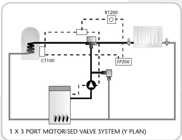
flowchart
graph TD
    A["CT100"] --> B["Valve System"]
    C["RT200"] --> D["Valve System"]
    E["EP200"] --> F["Valve System"]
    B --> G["Valve Component"]
    D --> H["Valve Component"]
    style A fill:#f9f,stroke:#333
    style C fill:#f9f,stroke:#333
    style E fill:#f9f,stroke:#333
    style B fill:#ccf,stroke:#333
    style D fill:#ccf,stroke:#333
    style F fill:#ccf,stroke:#333
    style G fill:#dfd,stroke:#333
    style H fill:#dfd,stroke:#333





Marque : Salus
Modèle : TC100
Catégorie : Maison intelligente