
GNSV75RWW - Filtre à eau GE - Notice d'utilisation et mode d'emploi gratuit
Retrouvez gratuitement la notice de l'appareil GNSV75RWW GE au format PDF.

| Type de produit | Système de filtration d'eau sous évier |
| Marque | GE |
| Modèle | GNSV75RWW |
| Capacité de filtration | 160 gallons (605 litres) |
| Débit | 0,60 gal/min (2,27 L/min) |
| Pression d'eau requise | 35 - 120 psi (2,4 - 8,2 bar) |
| Température d'eau maximale | 37,8 °C (100 °F) |
| Température ambiante minimale | 4,4 °C (40 °F) |
| Type de filtre | FQSVF (cartouche remplaçable) |
| Durée de vie du filtre | 6 mois ou 160 gallons |
| Substances réduites | Chlore, goût et odeur, plomb, kystes, turbidité, amiante, mercure, lindane, atrazine, benzène, COV, particules de classe I |
| Certifications | NSF/ANSI 42 et 53 |
| Alimentation du voyant | Pile CR2032 (incluse) |
| Matériaux | Plastique (manifold et cartouches) |
| Dimensions approximatives (L x H x P) | 25 x 30 x 15 cm (estimé) |
| Poids approximatif | 2,3 kg (sans eau) |
| Alimentation en eau requise | Eau froide potable uniquement |
| Installation | Sous évier, montage mural ou sur meuble |
| Garantie | 1 an (pièces et main-d'œuvre) |
| Service client | 800.626.2002 (États-Unis) |
FOIRE AUX QUESTIONS - GNSV75RWW GE
Questions des utilisateurs sur GNSV75RWW GE
0 question sur cet appareil. Repondez a celles que vous connaissez ou posez la votre.
Poser une nouvelle question sur cet appareil
Téléchargez la notice de votre Filtre à eau au format PDF gratuitement ! Retrouvez votre notice GNSV75RWW - GE et reprennez votre appareil électronique en main. Sur cette page sont publiés tous les documents nécessaires à l'utilisation de votre appareil GNSV75RWW de la marque GE.
MODE D'EMPLOI GNSV75RWW GE
Water Filtration System
Safety Instructions 2
System Overview 3-5
Installation Instructions 6-12
Battery Installation 11
Faucet Installation 7,8
Feed Water Supply 6,7
Filter Replacement 12
Flush Procedure 12
Installing the Tubing 11
System Installation 9, 10
Troubleshooting Tips 13
Consumer Support
Consumer Support.......Back Cover
Parts List/Catalog 14
Warranty 15
NSF
GNSV70RBL and GNSV75RWW are Tested and Certified by NSF International against NSF/ANSI Standard 42 for the reduction of Chlorine Taste and Odor and Particulate Class I and Standard 53 for the reduction of Lead, Cyst, Turbidity, Asbestos, Mercury, Lindane, Atrazine, Benzene and VOC.
Owner's Manual and Installation Instructions
GNSV7ORBL GNSV75RWW
WARNING: Read entire manual. Failure to follow all guides and rules could cause personal injury or property damage.
Check with your local public works department for plumbing codes. You must follow their guidelines as you install the Water Filtration system.
SAFETY PRECAUTIONS
■ Use the Water Filtration system on a potable, safe-to-drink, home COLD water supply only. The filter canisters will not purify the water, or make it safe to drink.
- Do not use on a hot water supply (100°F max.). Install on a cold water line only.
WARNING: To reduce the risk associated with the ingestion of contaminants, do not use with water that is microbiologically unsafe or of unknown quality without adequate disinfection before or after the system. Systems certified for cyst reduction may be used on disinfected water that may contain filterable cysts. EPA Establishment #10350-MN-005.
PROPER INSTALLATION
This Water Filtration system must be properly installed and located in accordance with the Installation Instructions before it is used.
A WARNING:
To reduce the risk associated with choking, do not allow children under 3 years of age to have access to small parts during the installation of this product.
To reduce the risk associated with hazardous voltage due to an installer drilling through existing electric wiring or water pipes in the area of installation, do not install near electric wiring or piping which may be in path of a drilling tool when selecting the position to mount the system bracket.
To reduce the risk of physical injury, depressurize system as shown in manual prior to cartridge removal.
CAUTION:To reduce the risk associated with property damage due to water leakage:
■ Read and follow Use Instructions before installation and use of this system.
■ Installation and use MUST comply with all state and local plumbing codes.
- Protect from freezing, remove filter cartridge when temperatures are expected to drop below 40^ F (4.4^ C).
■ Do not install systems in areas where ambient temperatures may go above 110^ F (43.3^)
■ Do not install on hot water supply lines. The maximum operating water temperature of this system is 100^ (37.8^)
■ Do not install if water pressure exceeds 120psi (827.4 kPa). If your water pressure exceeds 80 psi (551.6 kPa), you must install a pressure limiting valve. Contact a plumbing professional if you are uncertain how to check your water pressure.
■ Do not install where water hammer conditions may occur. If water hammer conditions exist you must install a water hammer arrester. Contact a plumbing professional if you are uncertain how to check for this condition.
■ Where a backflow prevention device is installed on a water system, a device for controlling pressure due to thermal expansion must be installed.
■ Do not use a torch or other high temperature sources near system, cartridges, plastic fittings or plastic plumbing.
- Do not install in direct sunlight or outdoors.
■ Do not install near water pipes which will be in path of a drilling tool when selecting the position to mount the bracket.
Mount system in such a position as to prevent it from being struck by other items used in the area of installation.
■ Ensure that the location and fasteners will support the weight of the system when installed and full of water.
■ Ensure all tubing and fittings are secure and free of leaks.
■ Do not install unit if collet is missing. Contact Customer Support if collets are missing from any fittings.
The disposable filter cartridge should be replaced every 6 months, at the rated capacity or sooner if a noticeable reduction in flow rate occurs.
■ On plastic fittings, never use pipe sealant or pipe dope. Use PTFE thread tape only as pipe dope may deteriorate the plastic.
READ AND FOLLOW THIS SAFETY INFORMATION CAREFULLY.
SAVE THESE INSTRUCTIONS
Specifications Guidelines.
The Water Filtration System Uses the Following Canisters
Models GNSV70RBL and GNSV75RWW
FQSVF Filter
(160 gallon capacity)
Filter—White canisters with green band
- Reduces dirt, rust and sediment
- Reduces Chlorine Taste and Odor
- Reduces Lead
- Reduces filterable Cysts (such as cryptosporidium and giardia)
- Reduces Turbidity
- Reduces Asbestos
- Reduces Mercury
- Reduces Lindane
- Reduces Atrazine
- Reduces Benzene
- Reduces VOC
- 0.5-1 micron nominal particulate reduction
This system conforms to NSF/ANSI 42 and 53 for the specific performance claims as verified and sustained by test data. See Performance Data Sheet for details.
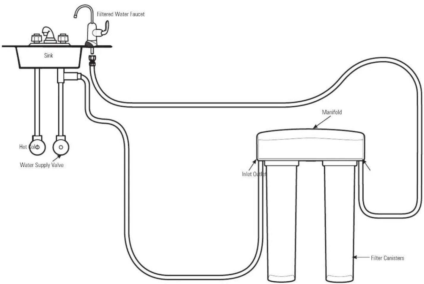
Installation Overview
Locate the drinking water system on the cold water supply pipe, under the kitchen and/or bathroom sink, to filter the cold drinking water.
Performance Data Sheet.
SmartWater Filtration System GNSV70RBL and GNSV75RWW Using Filter FQSVF
This System has been tested according to NSF/ANSI 42 and 53 for the reduction of the substances listed below. The concentration of the indicated substances in water entering the system was reduced to a concentration less than or equal to the permissible limit for water leaving the system, as specified in NSF/ANSI 42 and 53.
Actual performance may vary with local water conditions.
WARNING: To reduce the risk associated with the ingestion of contaminants, do not use with water that is microbiologically unsafe or of unknown quality without adequate disinfection before or after the system. Systems certified for cyst reduction may be used on disinfected water that may contain filterable cysts.
| Standard No. 42: Aesthetic Effects | ||||||||
| USEPA Influent | Influent | Challenge Concentration | Average | Effluent | % Reduction | Maximum Permissible Product Water Concentration | ||
| Average | Maximum | Average | Minimum | |||||
| Parameater | MCL | |||||||
| Chlorine taste and odor | - | 2.0 mg/L + 10% | 2.00 mg/L | <0.05 mg/L | <0.05 mg/L | 97.50% | 97.50% | >50% |
| Particulate** | - | ≥ 10000 particles | 4100000 Parts/mL | 76500 Parts/mL | 110000 Parts/mL | 98.10% | 97.30% | >85% |
| Standard No. 53: Health Effects | ||||||||
| Turbidity | 0.5 NTU*** | 11 + 1 NTU*** | 11.0 NTU | 0.1 NTU | 0.1 NTU | 98.80% | 98.20% | 0.5 NTU |
| Cysts**** | 99.95% red | Min. 50000L | 140000 Cyst/L | 1 Cyst/L | 1 Cyst/L | >99.99% | >99.99% | 99.95% |
| Asbestos | 99% red 10 | 7 and 103 fibers/L fibers >10 μm long | 280 MF/L | <0.17 MF/L | <0.17 MF/L | >99.00% | >99.00% | 99% |
| Lead, pH 6.5 | 0.010 mg/L | 0.15 mg/L + 10% | 0.150 mg/L | <0.001 mg/L | <0.001 mg/L | >99.30% | >99.30% | 0.010 mg/L |
| Lead, pH 8.5 | 0.010 mg/L | 0.15 mg/L + 10% | 0.140 mg/L | <0.001 mg/L | <0.001 mg/L | >99.30% | >99.30% | 0.010 mg/L |
| Mercury, pH 6.5 | 0.002 mg/L | 0.006 mg/L ± 10% | 0.0065 mg/L | <0.0002 mg/L | <0.0002 mg/L | 96.60% | >96.70% | 0.002 mg/L |
| Mercury, pH 8.5 | 0.002 mg/L | 0.006 mg/L ± 10% | 0.0059 mg/L | <0.0002 mg/L | <0.0002 mg/L | 96.60% | 96.70% | 0.002 mg/L |
| Lindane | 0.0002 mg/L | 0.002 mg/L ± 10% | 0.00193 mg/L | <0.00002 mg/L | 0.00005 mg/L | >98.80% | 98.80% | 0.0002 mg/L |
| Benzene | 0.001 mg/L | 0.015 mg/L ± 10% | 0.014 mg/L | <0.0005 mg/L | <0.0005 mg/L | >96.40% | >96.40% | 0.005 mg/L |
| Altrazine | 0.003 mg/L | 0.009 mg/L ± 10% | 0.00873 mg/L | <0.0005 mg/L | <0.0005 mg/L | >94.10% | >94.10% | 0.003 mg/L |
| VOCs | 0.080 mg/L | 0.300 ± 10% | 0.340 mg/L | 0.00098 mg/L | 0.00620 mg/L | 97.90% | 98.20% | 95% |
Tested using a flow rate of 0.60 gpm (2.27 l/min), pressure of 60 psig, pH of 7.5 ± 0.5; temp. of 68° ± 5°F (20° ± 3°C)
Measurement in particles/mL. Particles used were 0.5-1 microns.
**NTU-Nephelometric Turbidity Units.
****Based on the use of Cryptosporidium parvum oocysts.
Operating Specifications
Capacity: certified for up to 160 gallons (605 l)
Pressure requirement: 35-120 psi (2.4-8.2 bar)
Temperature: 33 - 100^ (0.6-38°C)
Flow rate: 0.60 gpm (2.27 l/min)
| TradeMark/Model Designation | Replacement Element(s) | ||
| GQYS65 F | FQSVF | FQSVF | |
| GNS70 FBL | FQSVF | FQSVF | |
| GNS75 FWV | FQSVF | FQSVF | |
| GNS75 RWV | FQSVF | FQSVF | |
| GNS70 RBL | FQSVF | FQSVF | |
| Manufacturer: General Electric Company | |||
| The water treatment device(s) listed on this certificate have met the testing requirements pursuant to Section 11689 of the Health and Safety Code for the following health related contaminants: | |||
| Microbiological Contaminants and Turbidity | Inorganic Radiological Contaminants | ||
| Cycles | Asbestos | ||
| Turbidity | Lead | ||
| Organic Contaminants | Mercury | ||
| Aerocine | Syringe | ||
| Carbon Tetrachloride | Tetrachloroethylene | ||
| Chlorophenone | Tetrachloroethylene | ||
| Chlorobenzene | Tetrachloroethylene | ||
| Carbon Monochlorinateds | 2,4-DTP (Silves) | ||
| Dibenzothiophene | 2,4-DTP (Silves) | ||
| Diisobromobenzene | 2,4-DTP (Silves) | ||
| O-Pentachlorophenone | 1,1-Dichloro-2-Propanone | ||
| 1,1-Dichloroethylene | 1,1-Dichloroethylene | ||
| 1,1-Dichlorobenzene | 1,1-Dichloro-2-Propanone | ||
| Hexachlorobenzene | 1,1-Dichloro-2-Propanone | ||
| 1,2-Dichloropropylene | 1,2-Dichloro-2-Propanone | ||
| Dinitrogen | Chromium | ||
| Methoxychlor | Chromium | ||
| Pentachlorophenol | Xylenes | ||
| Rated Service Capacity: 160 gal | Rated Service Flow: 0.6 gpm | ||
| Do not use where water is microbially unsafe or with water of unknown quality, except that systems certified for cyst reduction may be used on disinfected waters that may contain filterable casks. | |||
Organic Chemicals Reduced by Chloroform Surrogate Testing
| Avg. Contaminant | Influent (μg/L) | 1 | Max. 2 | Effluent (μg/L) | 3 |
| Alachlor | 50 1.0 | ||||
| Atrazine | 100 3.0 | 3 | |||
| Benzene | 81 1.0 | 3 | |||
| Carbofuran | 190 1.0 | 3 | |||
| Carbon Tetrachloride | 78 1.8 | 4 | |||
| Chlorobenzene | 77 1.0 | 3 | |||
| Chloropicrin | 15 0.2 | 4 | |||
| 2,4-D | 110 1.7 | 4 | |||
| Dibromochloropropane (DBCP) | 52 | 0.02 | 3 | ||
| α-Dichlorobenzene | 80 | 1.0 | 3 | ||
| p-Dichlorobenzene | 40 | 1.0 | 3 | ||
| 1,2-Dichloroethane | 88 | 4.8 | 5 | ||
| 1,1-Dichloroethylene | 83 | 1.0 | 3 | ||
| cis-1,2-Dichloroethylene | 170 | 0.5 | 3 | ||
| trans-1,2-Dichloroethylene | 86 | 1.0 | 3 | ||
| 1,2-Dichloropropane | 80 | 1.0 | 3 | ||
| cis-1,3-Dichloropropylene | 79 | 1.0 | 3 | ||
| Dinoseb | 170 | 0.2 | 4 | ||
| Endrin | 53 | 0.59 | 4 | ||
| Ethylbenzene | 88 | 1.0 | 3 | ||
| Ethylene Dibromide (EDB) | 44 | 0.02 | 3 | ||
| Haloacetonitriles (HAN): | |||||
| Bromochloroacetonitrile | 22 | 0.5 | 4 | ||
| Dibromoacetonitrile | 24 0.6 | 4 | |||
| Dichloroacetonitrile | 9.6 | \( {0.2}^{4} \) | |||
| Trichloroacetonitrile | 15 | 0.3 | 4 |
Influent challenge levels are average influent concentrations determined in surrogate qualification testing.
^2 g / L means Micrograms Per Liter.
3 Maximum product water level was not observed but was set at the detection limit of the analysis.
Maximum product level is set at a value determined in surrogate qualification testing.
Chemical reduction percent and maximum product water level calculated at chloroform 95% breakthrough point as determined in surrogate qualification testing.
The surrogate test results for heptachlor Epoxide demonstrated a 98% reduction. These data were used to calculate an upper occurrence concentration, which would produce a maximum product water level at the MCL.
Testing was performed under standard laboratory conditions; actual performance may vary.
NOTE: Substances reduced are not necessarily in your water. Filter must be maintained according to manufacturer's instructions, including replacement of filter cartridges.

WARNING: To reduce the risk associated with the ingestion of contaminants, do not use with water that is microbiologically unsafe or of unknown quality without adequate disinfection before or after the system. Systems certified for cyst reduction may be used on disinfected water that may contain filterable cysts.
Replacement Filter Canisters/Estimated Replacement Costs
FQSVF—Replacement filter canister $35-40
For replacement parts, call toll-free 800.626.2002 (U.S.), 800.663.6060 (Canada-English), 800.361.3869 (Canada-French)
Installation Instructions
Faucet Mount Filtration System –
GNSV70RBL and GNSV75RWW
IMPORTANT INSTALLATION RECOMMENDATIONS
WARNING - Read entire manual. Failure to follow all guides and rules could cause personal injury or property damage
- Check with your local public works department for plumbing codes. You must follow their guides as you install the Water Filtration system.
TOOLS AND MATERIALS REQUIRED FOR INSTALLATION
Phillips screwdriver
- Two (2) adjustable wrenches
Electric drill and drill bit to drill 1" hole (type as required) if mounting hole is needed for faucet
- Tape measure
If your main water line is a rigid pipe, you will require compression fitting and possibly other plumbing hardware to complete the installation.
CAUTION - To avoid damaging the sink or countertop, consult a qualified plumber or installer for drilling procedures. Special drill bits may be needed for stone, porcelain or stainless steel.
CONTENTS INCLUDED WITH THE PRODUCT
Water filter system assembly, including mounting screws
Feed water adapter
- Faucet assembly with electronic base monitor and tubing
COLD WATER SUPPLY FITTING
A. PREFERRED INSTALLATION
(Utilizing existing kitchen sink water supply valve and flexible faucet tubing)
A typical connection using the included water supply fitting is shown in the illustration below.
- Close the water shut-off valve that is immediately in front of the supply tube and open the faucets to drain water from the sink cold water pipe.
- Remove the nut that connects the cold water faucet to the supply tube. Some water may spill out.
NOTES:
- Be sure to turn off the water supply and open a faucet to drain the pipe.
Make sure the gasket is installed in the water supply fitting.
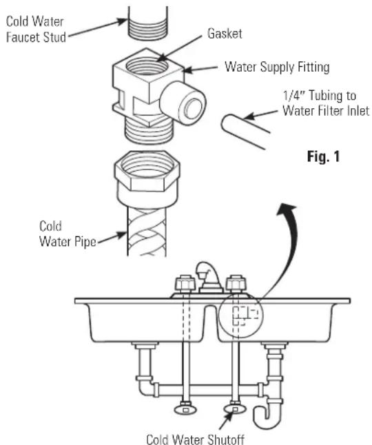
- Hand-tighten the water supply fitting onto the cold water faucet. Be sure the gasket, as shown, is in place before final assembly. Finish tightening with an adjustable wrench. Be careful not to overtighten or cross-thread, as damage to the threads can occur. Make sure the 1/4'' quick connection is not against a wall that causes the supply tubing connection to bend. A quarter turn to tighten or loosen the adapter may be necessary to avoid this.
- Reconnect faucet tubing line to the fitting.
- Install tubing. (See Installing the Tubing section.)
COLD WATER SUPPLY FITTING (CONT.)
B. OPTIONAL HOME INSTALLATION
(Where codes permit)
Saddle Valve: Saddle valve must be able to connect with 1/4-inch tubing supplied with the system. Not supplied with product; check your local hardware or home service store for product. Saddle valve typically requires 1/2'' OD tubing or larger.
NOTE: Codes in certain states require installation by a licensed plumber and do not permit the use of the saddle valve. For installation, use plumbing code 248-CMR of the Commonwealth of Massachusetts.
- Turn off the cold water supply and install saddle valve as required by product selection. (Be sure to follow manufacturer's installation instructions.)
DANGER If hole is required to be drilled in pipe, to protect yourself from serious injury or fatal shock, use a battery-powered hand drill only to make the hole. DO NOT USE AN ELECTRIC DRILL.
- Open saddle valve after complete system has been installed.
C. OPTIONAL INSTALLATION
(For installation with rigid pipe between supply valve and sink faucet)
Option 1
- Remove pipe from supply valve and sink faucet.
- Obtain flexible pipe sized to your plumbing.
- Install flexible pipe.
- Go back to A. Preferred Installation section step 3.
Option 2
- Obtain compression fittings to fit rigid pipe.
- Obtain any other fittings required to connect compression fittings to feed water adapter.
- Remove pipe from supply valve.
- Cut pipe to fit length of assembled fittings and adapter.
- Install compression fitting to pipe.
- Go back to A. Preferred Installation section step 3.
NOTE: Above described materials are not included with the product.
INSTALL THE FAUCET
Be sure there is room underneath and above the sink to make the needed connections. Before starting, make sure there is sufficient room for the faucet base and unit. Select one of the following places to install the faucet:
A. In an existing sink spray attachment or soap dispenser hole.
B. In a hole to be drilled in the sink top.
C. In a hole to be drilled in the countertop, next to the sink.
NOTES:
- Be sure the faucet base will fit flat against the surface at the selected location so the bottom gasket between the base and surface area will seal.
Make sure to leave enough clearance at the back of the faucet in case you need to remove it.
Installation Steps (refer to illustration below for clarification)
- If drilling is needed, make a 1'' diameter hole. Be sure to use the proper procedure for drilling stone, porcelain or stainless steel. Special drill bits may be needed. Consult a qualified plumber for the proper procedure.
CAUTION: When drilling in Stainless
Steel, the edges may be sharp and could puncture the tube. Be careful to not cut yourself or damage the tube.
- Remove the faucet body and base by turning the base counterclockwise.
- Remove the butterfly bracket from the screw. Then insert the screw into the top of the base and reattach the butterfly bracket.
- Align the gasket to cover the hole completely. Then place the butterfly bracket on the base into the hole.
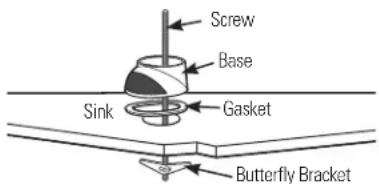
- Tighten the screw to secure the butterfly bracket to the underside of the sink top. The base should be firmly in place and should not wobble or turn.
INSTALL THE FAUCET (CONT.)
- Feed the water tube up through the faucet base. Then push the tube into the fitting on the bottom of the faucet body. It should go in about 3/4'' . Pull tube slightly to make sure it is secure.

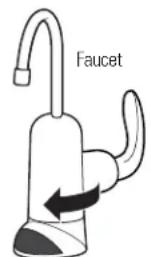
- Push the faucet body down into the faucet base and twist clockwise until it clicks into place.
NOTE: You can install the faucet so the handle is on the right or the left side.
If you want the faucet handle on the right, position the handle at the back of the faucet base before turning clockwise.
If you want the faucet handle on the left, position the handle at the front of the faucet base before turning clockwise.
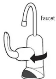
Faucet handle on the RIGHT. Faucet handle on the LEFT
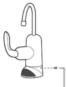
- Locate the hole at the rear of the base. Insert set screw and begin to tighten by hand. Finish tightening with the allen wrench provided in the packet.
MOUNTING SYSTEM INSTALLATION
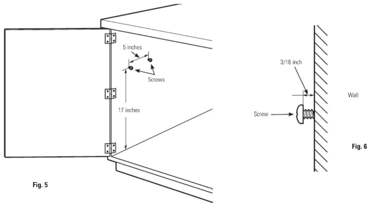
Pick a location under the sink to mount the system. Location should be easily accessible, with clearance between the bottom of the filter canisters and the floor or bottom of the cabinet; any less will result in difficulty of removing filter canisters (see Fig. 5). Allow enough space on either side of the system for the tubing connections.
SCREW INSTALLATION
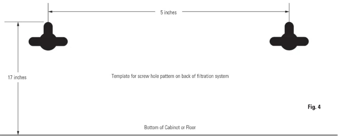
- Remove this template from the manual for easier installation.
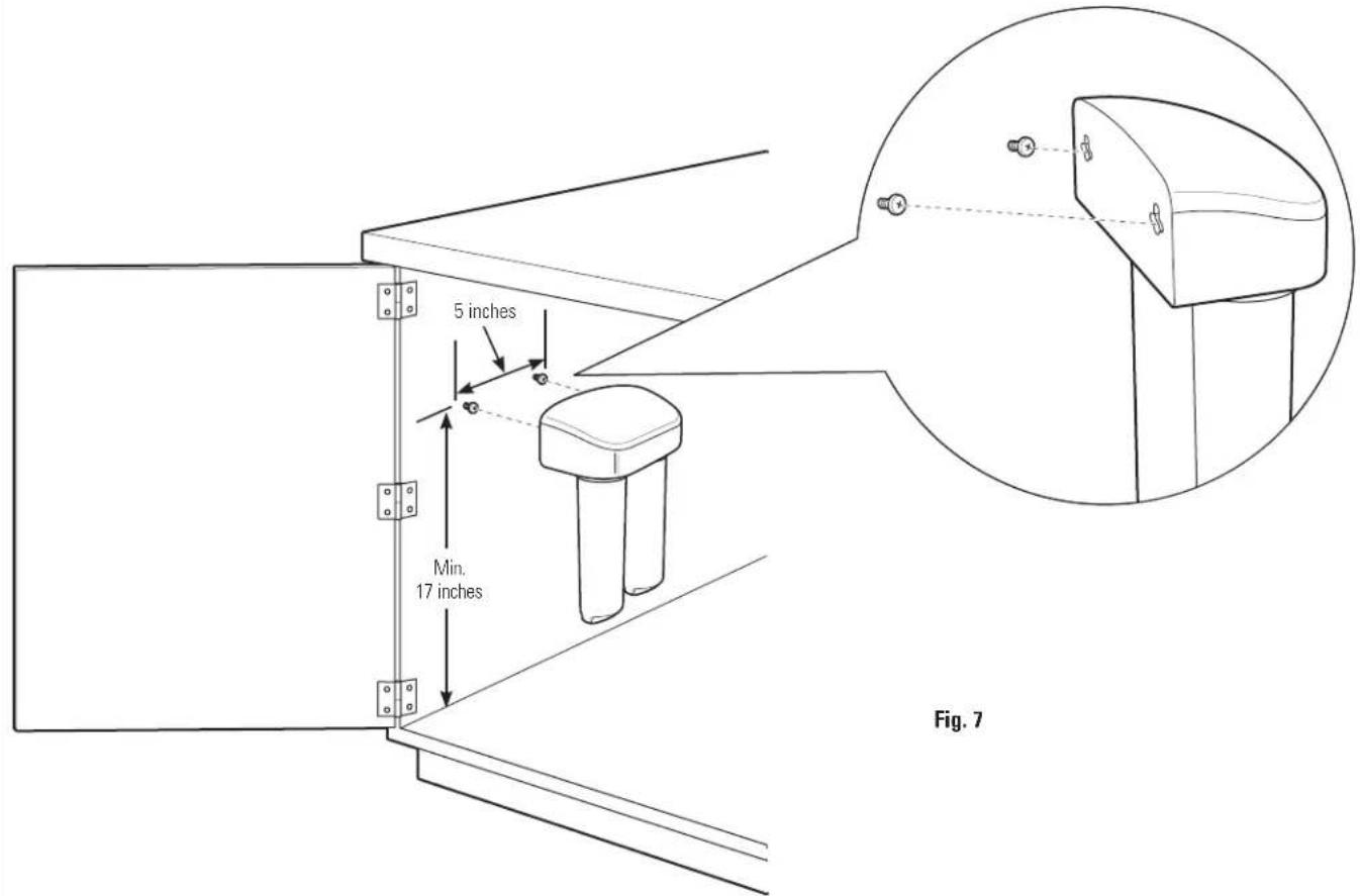
- The top of the template openings should be placed a minimum of 17 inches above the bottom of the cabinet or floor where the system is to be mounted (Fig. 4 and 5). NOTE: Any distance lower may result in filter canisters interfering with the floor when removed.
- Tape template to wall, then mark the wall where the screws are to be installed.
Install screws into the wall, leaving 3/16 inch clearance between the head of the screw and wall (drill pilot holes if needed) (Fig. 6).
MOUNTING SYSTEM INSTALLATION (CONT.)
Mounting System to Screws Installed in Wall
- Remove shrink wrap from filter system.
- Hang the system on the previously installed screws using the openings on the back of the unit (Fig. 7).
- If the head of the screw will not slide into the upper slot, back out the screw by 1/4 turn and try again.
- If the system is too loose when placed on the wall, tighten the screws by 1/4 turn and try again until a desired fit is achieved. Alternatively, it is possible to remove the top of the manifold during installation and tighten the screws to achieve the desired fit. DO NOT OVERTIGHTEN. Replace the top of the manifold when complete.
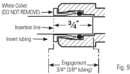
INSTALLING THE TUBING
- Measure 3/4'' from the end of each remaining piece of tubing (f aquet end and inlet end) and mark with a pencil (Fig. 8). (Check for roundness, smoothness, cuts, nicks, flat spots and sharp edges. It may be necessary to recut the tubing.)
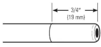
Fig. 8
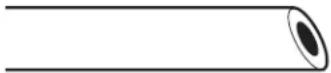
INCORRECT
- Locate fittings for tubing on bottom of manifold.
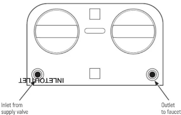
- NOTE: Water flow is from left to right. Water inlet is on the left side and water outlet is on the right side. Failure to follow will result in water leaks when filter canisters are removed.
- Push the tubing firmly into each fitting on the manifold until the line is flush with the fitting collar. (If the tubing is removed, re-cut the end, measure, mark and re-insert). Tubing must be fully inserted to avoid leaks (Fig. 9). (To remove tubing, depress and hold white collet; pull tubing out to remove.)
INSTALLING THE TUBING (CONT.)
- Pull out slightly on tubing to ensure a good seal.
- Install the other end of the tubing from the inlet side of the manifold to the feed water adapter.
NOTE: Inspect the ends of the tubing to be sure there are no imperfections and that the end of the tubing is cut square. It may be necessary to cut the tubing again.
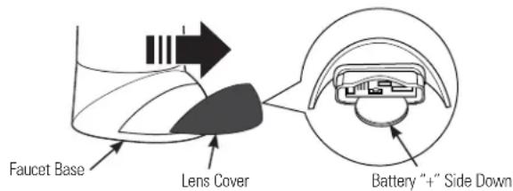
INSTALL THE BATTERY
- Remove the lens cover from the faucet base. Grip it from both sides and pull forward.
- Install one CR2032 3V battery with the "+" side down into the battery tray.
- The amber LED light will flash 5 times, indicating a proper installation and system reset. If the amber light does not flash, check the position of the battery and make sure it is installed correctly.
- Slide the lens cover back into the faucet base.
- Normally, the light is off. After 6 months of use, the amber LED light will flash every 30 seconds, indicating the time to replace the filter canister.
NOTE: The amber LED light may stop blinking if it is allowed to blink for an extended period of time. To ensure proper operation, the battery should be replaced with every filter change.
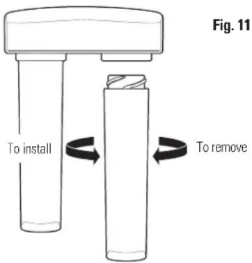
REPLACING THE FILTER CANISTERS
The amber light in the faucet base will flash every 30 seconds to indicate a filter change is needed. This occurs every 6 months. TO PROPERLY MAINTAIN THE SYSTEM AND REDUCE THE RISK OF PROPERTY DAMAGE DUE TO WATER LEAKAGE, CHANGE THE FILTER AS REQUIRED.
- Remove the filter canisters from the manifold by rotating the canisters to the left about 1/3 turn (Fig. 11). NOTE: A small amount of water from the tubing between the filter and the faucet may come out. A small towel should be able to catch it.
- Remove foil on top of new replacement filter canisters. Install the new canisters into the manifold by turning to the right about 1/3 turn until the alignment marks line up and the filter stops. DO NOT OVERLIGHTEN. The filter will rise up as it is turned.
- Turn handle on faucet to allow trapped air to purge from the system.
NOTE: System may make noise during this procedure.
- Check for water leaks around the system.
- Once water starts to flow out of the faucet, flush 3 gallons through the system (up to 5 minutes depending on flow rate) to flush out any harmless carbon fines that may be present.
- Turn off faucet and check around system for leaks.
- Remove battery tray and replace battery to reset timer. (See Battery Installation for proper procedure.)
Replacement Filter Canisters/ Estimated Replacement Costs
FQSVF—Replacement filter canister 35- 40
For replacement parts, call toll-free 800.626.2002 (U.S.), 800.663.6060 (Canada-English), 800.361.3869 (Canada-French).
FLUSH PROCEDURE
Whenever water of unknown quality is passed through the GE Water Filtration system, the filter canisters should be discarded and the filtration system flushed.
WARNING: To reduce the risk associated with the ingestion of contaminants, do not use with water that is microbiologically unsafe or of unknown quality without adequate disinfection before or after the system. Systems certified for cyst reduction may be used on disinfected water that may contain filterable cysts.
Circumstances that may require flushing the system are:
- Boil water advisory
- Flooding of the GE Water Filtration system
- Long-term non-use
The procedure for flushing the GE Water Filtration system is:
- See 5HSODFLQJWKH)LOWHU&DQLVWHUV section o steps 1-5.
Before you call for service...
| Troubleshooting Tips Save time and money! Review the chart below first and you may not need to call for service. | ||
| Problem | Possible Causes | What To Do |
| Water contains tiny black particles | New filter canisters contain activated carbon. | •Turn on the filtered water faucet and flush 3 gallons through the system (up to 5 minutes depending on flow rate) to flush out any harmless |
| carbon fines that may be present. | ||
| Water has air bubbles and is cloudy | Air in system after installation. | •Will go away after water runs for a while. |
| Indicator light on the faucet base is flashing | Six months usage has occurred. This is the maximum life of the filter canisters. | •Replace both filter canisters and battery in the faucet base. |
| Indicator light on the faucet base is not blinking | Normal operation. | •Does not blink until 6 months of operation has passed. |
| Battery may need to be replaced. | •Normally the light is not on. The light blinks every 30 seconds to indicate a filter change is needed. This occurs about every 6 months. | |
| •Replace battery. Indicator light will blink rapidly 5 times to indicate proper installation and operation. | ||
| Indicator light on the faucet base is not working when new battery is installed | Battery may need to be replaced or it may have been installed incorrectly. | •Observe orientation markings on the holder. Install with battery "+" side down. |
| Chlorine taste and odor in the product water | The filter canisters are no longer reducing chlorine taste and odor from the water supply. | •Replace the filter canisters. |
| Water dispenses very slowly | The filters have been installed for too long. | •A six-month change-out period is recommended. Replace both filter canisters. |
| The filter canisters have become clogged. | •High sediment levels can cause premature clogging. Replace both filter canisters. | |
| Fittings are leaking | Tubing may not be installed properly. | •Fully follow the installation instructions and be sure the tubing is free of nicks, burrs, etc., and is installed to the proper depth. |
| No water dispensing from system | Filter canisters not fully installed. | •Fully follow the filter replacement instructions. |
GNSV70RBL, GNSV75RWW
To obtain replacement parts, call toll-free 800.626.2002 (U.S.), 800.663.6060 (Canada- English), 800.361.3869 (Canada-French)
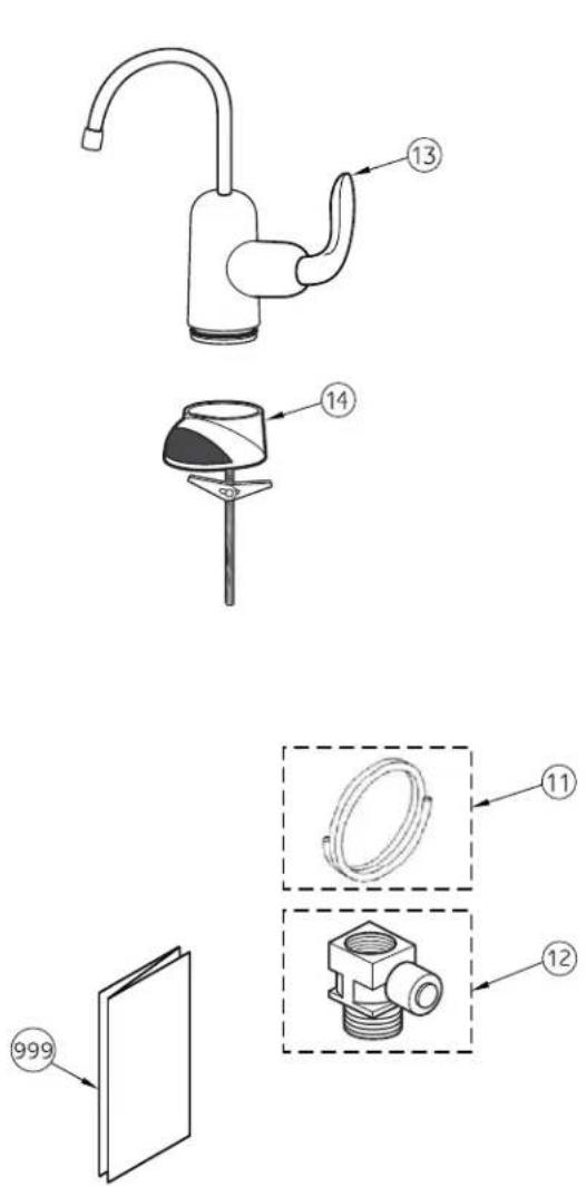
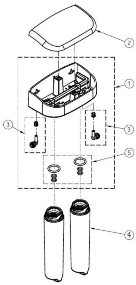
General Electric parts catalog.
| GNSV70RBL GNSV75RWW | |||
| (00) (00) | |||
| ITEM | GE CAT. NO. | DESCRIPTION | QTY QTY |
| 1 | WS19X10016 | MANIFOLD ASSEMBLY 1 1 | |
| 2 | WS19X10015 | COVER, DUAL MANIFOLD | 1 1 |
| 3 | WS22X10045 | ELBOW & COLLET | 2 2 |
| 4 | FQSVF | FILTER SET (VOC) | 1 1 |
| 5 | WS03X10046 | O-RING KIT (2 LG, 4 SM) | 1 1 |
| 11 | WS07X10020 | TUBING-6'0" | |
| 12 | WS60X10016 | INLET ADAPTER-NO VALVE | |
| 13 | WS15X10068 | FAUCET BODY, CHROME | |
| 13 | WS15X10069 | FAUCET BODY, WHITE | |
| 14 | WS10X10039 | FAUCET BASE, CHROME | |
| 14 | WS10X10040 | FAUCET BASE, WHITE | |
| 999 | 49-50234-5 | OWNER'S MANUAL & INST. INSTR. | |
GE Water Filtration System Warranty.

All warranty service provided by our SmartWater™ Authorized Servicer Network. To schedule service, on-line, visit us at GEAppliances.com, or call 800.952.5039 in the U.S., or toll-free 866.777.7627 in Canada. Please have serial number and model number available when calling for service.
Staple your receipt here. Proof of the original purchase date is needed to obtain service under the warranty.
For The Period Of: GE Will Replace:
One Year
From the date of the original purchase of
Any part of the Water Filtration System (excluding filters) which fails due to a defect in materials
or workmanship. During this limited one-year warranty, GE will also provide, free of charge, all labor
and related service to replace the defective part.
What GE Will Not Cover:
Service trips to your home to teach you how to use the product.
Improper installation, delivery or maintenance.
Failure of the product if it is abused, misused, or used for other than the intended purpose or used commercially.
Use of this product where water is microbiologically unsafe or of unknown quality, without adequate disinfection before or after the system. Systems certified for cyst reduction may be used on disinfected water that may contain filterable cysts.
Filter cartridges and batteries after 30 days from date of purchase.
- Damage to the product caused by accident, fire, floods or acts of God.
- Incidental or consequential damage caused by possible defects with this appliance.
EXCLUSION OF IMPLIED WARRANTY--Your sole and exclusive remedy is product repair as provided in this Limited Warranty. Any implied warranties, including the implied warranties of merchantability or fitness for a particular purpose, are limited to one year or the shortest period allowed by law.
This warranty is extended to the original purchaser and any succeeding owner for products purchased for home use within the USA. If the product is located in an area where service by a GE Authorized Servicer is not available, you may be responsible for a trip charge or you may be required to bring the product to an Authorized GE Service location for service. In Alaska, the warranty excludes the cost of shipping or service calls to your home.
Some states do not allow the exclusion or limitation of incidental or consequential damages. This warranty gives you specific legal rights, and you may also have other rights which vary from state to state. To know what your legal rights are, consult your local or state consumer affairs office or your state's Attorney General.
Warrantor: General Electric Company. Louisville, KY 40225
GE Appliances Website
GEAppliances.com
Have a question or need assistance with your appliance? Try the GE Appliances Website 24 hours a day, any day of the year! For greater convenience and faster service, you can now download Owner's Manuals, order parts or even schedule service on-line.
Schedule Service GEAppliances.com
Expert GE repair service is only one step away from your door. Get on-line and schedule your service at your convenience any day of the year! Or call 800.GE.CARES (800.432.2737) during normal business hours.
Real Life Design Studio GEAppliances.com
GE supports the Universal Design concept—products, services and environments that can be used by people of all ages, sizes and capabilities. We recognize the need to design for a wide range of physical and mental abilities and impairments. For details of GE's Universal Design applications, including kitchen design ideas for people with disabilities, check out our Website today. For the hearing impaired, please call 800.TDD.GEAC (800.833.4322).
Extended Warranties GEAppliances.com
Purchase a GE extended warranty and learn about special discounts that are available while your warranty is still in effect. You can purchase it on-line anytime, or call 800.626.2224 during normal business hours. GE Consumer Home Services will still be there after your warranty expires.
Parts and Accessories GEAppliances.com
Individuals qualit to service their own apianies can have parts or accessories sent directly to their homes (VSA, MasterCard and Discover cards are accepted). Order on-line today, 24 hours every day or by phone at 800.626.2002 during normal business hours. Instructions contained in this manual cover procedures to be performed by any user. Other servicing generally should be referred to qualified service personnel. Caution must be exercised, since improper servicing may cause unsafe operation.

Contact Us GEAppliances.com
If you are not satisfied with the service you receive from GE, contact us on our Website with all the details including your phone number, or write to: General Manager, Customer Relations GE Appliances, Appliance Park Louisville, KY 40225
Register Your Appliance GEAppliances.com
Register your new appliance on-line-at your convenience! Timely product registration will allow for enhanced communication and prompt service under the terms of your warranty, should the need arise. You may also mail in the preprinted registration card included in the packing material.
| IOWA RESIDENTS ONLY: | ||
| Store or Seller's Name | ||
| Address | ||
| City | State | Zip |
| Seller's signature | ||
| Customer's signature | ||
| Date | ||

- Water Filtration System
- NSF
- SAFETY PRECAUTIONS
- PROPER INSTALLATION
- SAVE THESE INSTRUCTIONS
- Specifications Guidelines.
- The Water Filtration System Uses the Following Canisters
- Models GNSV70RBL and GNSV75RWW
- Installation Overview
- Performance Data Sheet.
- SmartWater Filtration System GNSV70RBL and GNSV75RWW Using Filter FQSVF
- Operating Specifications
- Replacement Filter Canisters/Estimated Replacement Costs
- Installation Instructions
- Faucet Mount Filtration System –
- GNSV70RBL and GNSV75RWW
- IMPORTANT INSTALLATION RECOMMENDATIONS
- TOOLS AND MATERIALS REQUIRED FOR INSTALLATION
- CONTENTS INCLUDED WITH THE PRODUCT
- COLD WATER SUPPLY FITTING
- PREFERRED INSTALLATION
- NOTES:
- COLD WATER SUPPLY FITTING (CONT.)
- OPTIONAL HOME INSTALLATION
- OPTIONAL INSTALLATION
- Option 1
- Option 2
- INSTALL THE FAUCET
- Installation Steps (refer to illustration below for clarification)
- INSTALL THE FAUCET (CONT.)
- MOUNTING SYSTEM INSTALLATION
- SCREW INSTALLATION
- MOUNTING SYSTEM INSTALLATION (CONT.)
- Mounting System to Screws Installed in Wall
- INSTALLING THE TUBING
- INSTALLING THE TUBING (CONT.)
- INSTALL THE BATTERY
- REPLACING THE FILTER CANISTERS
- NOTE: System may make noise during this procedure.
- Replacement Filter Canisters/ Estimated Replacement Costs
- FLUSH PROCEDURE
- Circumstances that may require flushing the system are:
- The procedure for flushing the GE Water Filtration system is:
- Before you call for service...
- GE Water Filtration System Warranty.
- For The Period Of: GE Will Replace:
- One Year
- What GE Will Not Cover:
- GE Appliances Website
- GEAppliances.com
- Schedule Service GEAppliances.com
- Real Life Design Studio GEAppliances.com
- Extended Warranties GEAppliances.com
- Parts and Accessories GEAppliances.com
- Contact Us GEAppliances.com
- Register Your Appliance GEAppliances.com
Marque : GE
Modèle : GNSV75RWW
Catégorie : Filtre à eau