
CP 6663.400 - Support articulé Rittal - Notice d'utilisation et mode d'emploi gratuit
Retrouvez gratuitement la notice de l'appareil CP 6663.400 Rittal au format PDF.

| Type de produit | Support articulé (bras porteur) |
| Marque | Rittal |
| Modèle | CP 6663.400 |
| Poids | 4,5 kg |
| Matière | Acier inoxydable (Edelstahl) |
| Charge admissible statique max. | 800 N (pour un montage sans porte-à-faux) |
| Dimensions (environ) | Longueur ajustable, voir schéma |
| Couple de serrage recommandé (M8) | 25 Nm |
| Couple de serrage recommandé (M10) | 20 Nm |
| Couple de serrage recommandé (M12) | 30 Nm |
| Angle de rotation | 180° (positions réglables à 60°, 120°, 180°) |
| Fixation murale | Via platine avec 4 trous M8 |
| Utilisation | Support pour armoires électriques, écrans, etc. |
| Entretien | Nettoyer avec un chiffon doux ; vérifier les serrages périodiquement |
| Température de fonctionnement | -20°C à +60°C (estimation) |
| Certification | Conforme aux normes CE |
FOIRE AUX QUESTIONS - CP 6663.400 Rittal
Questions des utilisateurs sur CP 6663.400 Rittal
0 question sur cet appareil. Repondez a celles que vous connaissez ou posez la votre.
Poser une nouvelle question sur cet appareil
Téléchargez la notice de votre Support articulé au format PDF gratuitement ! Retrouvez votre notice CP 6663.400 - Rittal et reprennez votre appareil électronique en main. Sur cette page sont publiés tous les documents nécessaires à l'utilisation de votre appareil CP 6663.400 de la marque Rittal.
MODE D'EMPLOI CP 6663.400 Rittal
Rittal – The System.
Faster – better – everywhere.
text_image
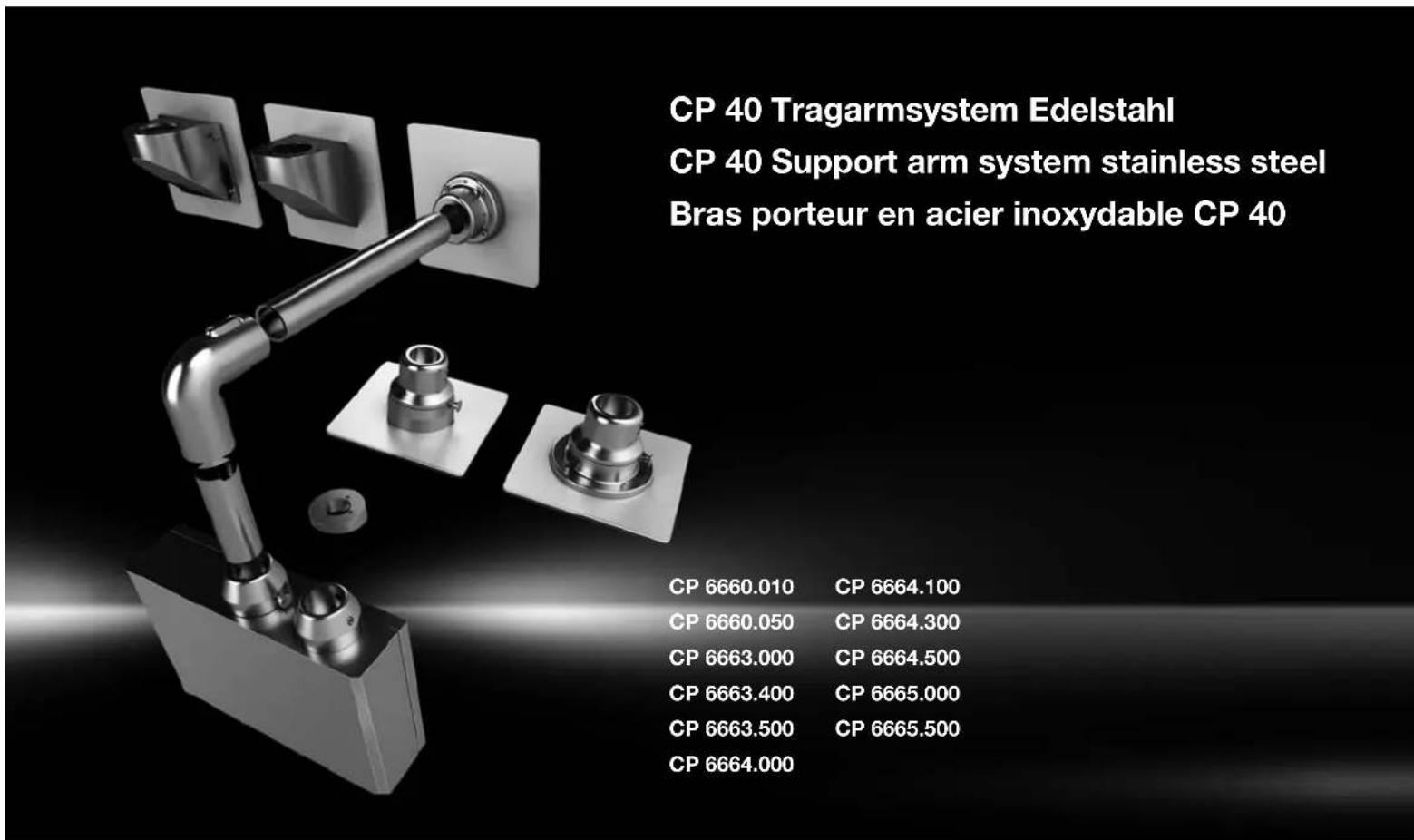
CP 40 Tragarmsystem Edelstahl CP 40 Support arm system stainless steel Bras porteur en acier inoxydable CP 40 CP 6660.010 CP 6664.100 CP 6660.050 CP 6664.300 CP 6663.000 CP 6664.500 CP 6663.400 CP 6665.000 CP 6663.500 CP 6665.500 CP 6664.000Montage- und Bedienungsanleitung Assembly and operating instructions Notice d'emploi et de montage

flowchart
graph LR
    A["ENCLOSURES"] --> B["POWER DISTRIBUTION"]
    B --> C["CLIMATE CONTROL"]
    C --> D["IT INFRASTRUCTURE"]
    D --> E["SOFTWARE & SERVICES"]
    E --> F["RITTAL"]
FRIEDHELM LOH GROUP

RITTAL

Inhaltsverzeichnis/Contents/Sommaire
text_image
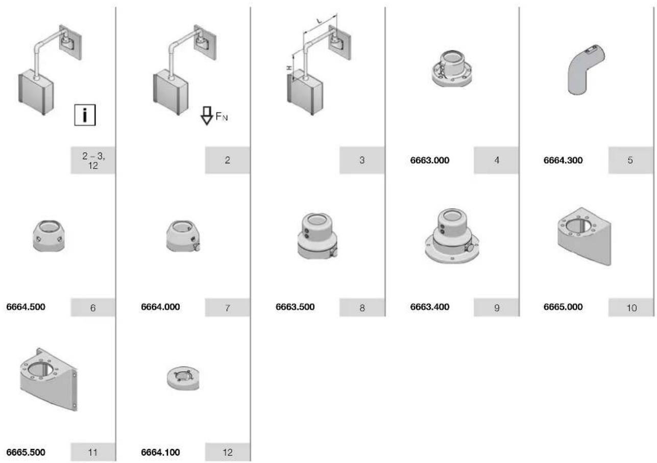
i 2-3, 12 FN 6664.500 6 6664.000 7 6663.500 8 6663.000 4 6664.300 5 6663.400 9 6665.000 10 6665.500 11 6664.100 12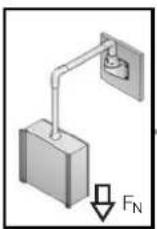
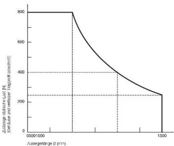
Belastbarkeit/Load capacity/Charge admissible
Zulässige Belastung in Abhängigkeit vom Systemaufbau Permissible load depending on system confi guration Charge admissible en fonction de la confi guration choisie
line
| Auslegerlänge B (mm) | Zusässige statische Last [N] (Genaube und vertrikaler Tragsorff (abschnitt)) | | --------------------- | ------------------------------------------------------------------------------------------ | | 0 | 800 | | 1500 | 250 |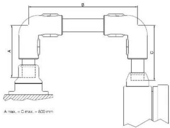
text_image
A B C A max. = C max. = 800 mm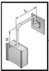
 |  |  | |||
| 0,7 kg | 6664.100 | 1,3 kg | 6664.500 | 1,1 kg | 6664.000 |
 |  | ||||
| 1,3 kg | 6664.300 | 1,7 kg | 6663.000 | ||
 |  |  | |||
| 3,9 kg | 6663.500 | 4,5 kg | 6663.400 | 1,5 kg | 6665.000 |
 |  | ||||
| 1,8 kg | 6665.500 | 500 mm 2,0 kg | 6660.050 | ||
| 1000 mm 3,9 kg | 6660.010 | ||||
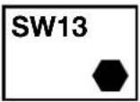
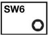
SW5/6 SW

13 mm

D
ENF
O
CP 6663.000
text_image
Technical diagram of a mechanical assembly with numbered components and directional arrows indicating motion or assembly steps.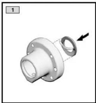
natural_image
3D mechanical component diagram showing a flanged housing with a loop and a dashed line indicating assembly (no text or symbols)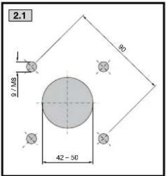
text_image
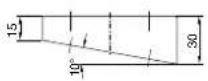
2.1 9 / M8 90 42 - 50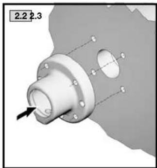
natural_image
3D mechanical component diagram with flanged ends and a central arrow indicator (no text or symbols)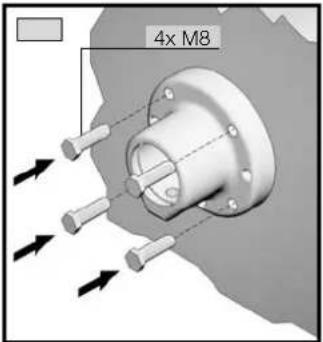
text_image
4x M8
natural_image
Technical line drawing of a pipe joint with a valve and adjustment mechanism (no text or symbols)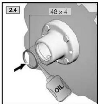
text_image
2.4 48 x 4 OIL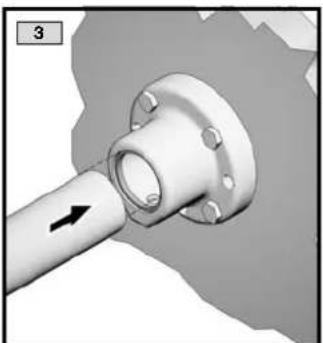
natural_image
3D rendered mechanical pipe fitting with a black arrow indicating direction (no text or symbols)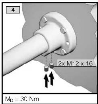
text_image
4 2x M12 x 16 MD = 30 Nm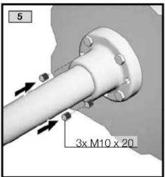
text_image
5 3x M10 x 20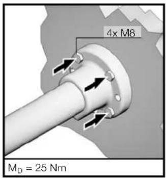
text_image
4x M8 MD = 25 Nm
CP 6664.300
text_image
Technical diagram of a pipe fitting with numbered components and directional arrows indicating assembly or assembly steps.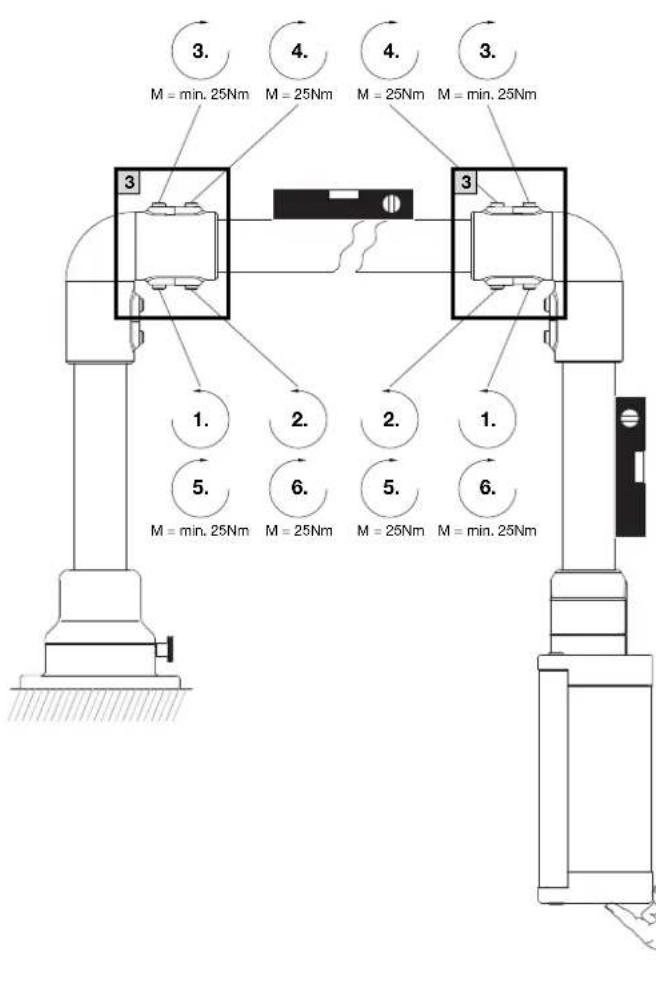
text_image
3. M = min. 25Nm 4. M = 25Nm 4. M = 25Nm 3. 3. 1. 2. 2. 1. 5. M = min. 25Nm 6. M = 25Nm 5. M = 25Nm 6. M = min. 25Nm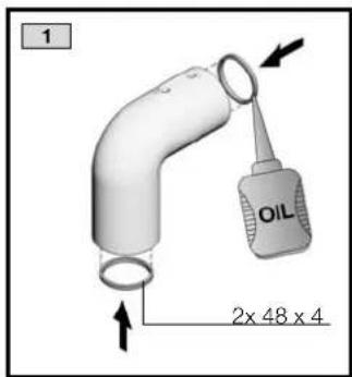
text_image
1 OIL 2x 48 x 4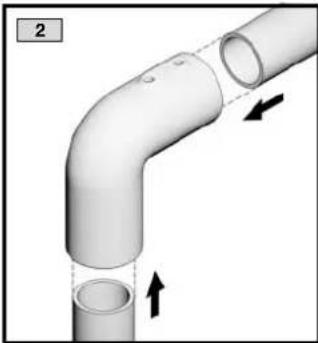
natural_image
3D diagram of a pipe elbow joint with two circular openings and directional arrows indicating flow or movement (no text or symbols)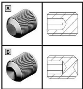
natural_image
Four technical diagrams (A and B) showing threaded mechanical parts with cross-sectional views, no text or symbols present.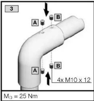
text_image
3 A B A B 4x M10 x 12 M_D = 25 Nm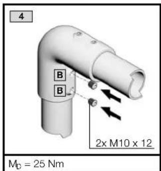
text_image
4 B B 2x M10 x 12 MD = 25 Nm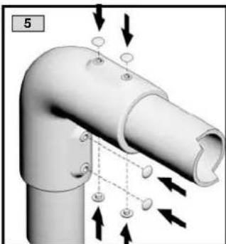
natural_image
3D diagram of a pipe elbow joint with directional arrows indicating flow or movement (no text or symbols)
EN
GEFAHR!
■ Unmittelbare Gefahr für Leib und Leben.
Halten Sie die auf Seite 2 vorgegebenen Belastungsangaben ein. Halten Sie alle vorgegebenen Drehmoment angaben ein. Ein Über- bzw. Unterschreiten der in dieser Anleitung vorgegebenen Anzugsdrehmomente kann zu Anlagenschäden oder zu schweren bis hin zu tödlichen Verletzungen führen.
Es sind geeignete Maßnahmen zur stabilen und dauerhaften Befestigung des Tragarmsystems an der Montage-fl äche zu ergreifen!
■ DANGER!
- Immediate danger to life and limb.
Observe the load specifi cations given on page 2.
Observe all specifi ed tightening torques. If screws or bolts are tightened with torques greater or less than those specifi ed in these instructions, this may result in damage and serious or even fatal injuries.
■ Please ensure that the support arm system is securely and permanently fastened to the mounting surface!
■ DANGER!
■ Danger de mort immédiat pour la personne.
Respectez les charges mentionnées à la page 2.
Respectez les couples indiqués. Un dépassement vers le haut ou
vers le bas des couples indiqués dans cette notice peuvent con-
duire à des dommages au niveau de l'installation ou à de graves
blessures qui peuvent même être mortelles.
Il faut prendre les mesures appropriées pour fixer solidement et de manière durable le bras porteur sur sa surface de montage !

CP 6664.500
text_image
Exploded view diagram of a mechanical assembly with numbered components and directional arrows indicating assembly steps.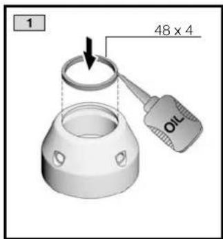
text_image
1 48 x 4 OIL
natural_image
3D rendering of a mechanical component with a conical base and mounting holes, showing an upward arrow (no text or symbols)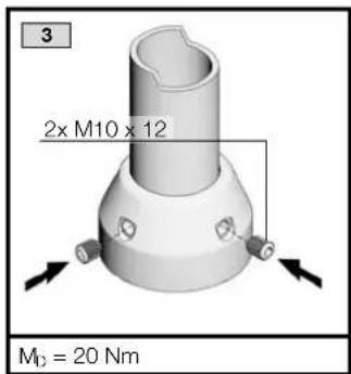
text_image
3 2x M10 x 12 M₀ = 20 Nm
text_image
4 76 x 3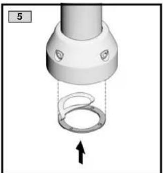
natural_image
3D rendering of a mechanical component with a curved ring and dashed line indicating internal structure (no text or symbols)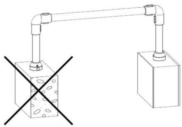
natural_image
Simple line drawing of a mechanical setup with two connected pipes and a cube, no text or symbols present.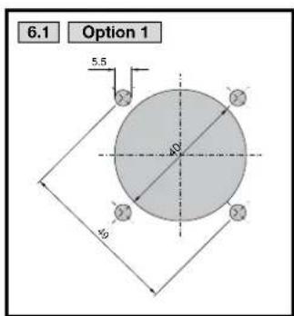
text_image
6.1 Option 1 5.5 40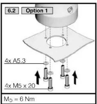
text_image
6.2 Option 1 4x A5.3 4x M5 x 20 MD = 6 Nm
text_image
6.1 Option 2 9 40 62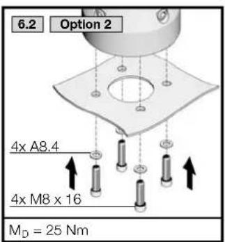
text_image
6.2 Option 2 4x A8.4 4x M8 x 16 MD = 25 Nm

CP 6664.000
text_image
Exploded view diagram of a mechanical assembly with numbered components and directional arrows indicating assembly steps.
text_image
1 48 x 4 OIL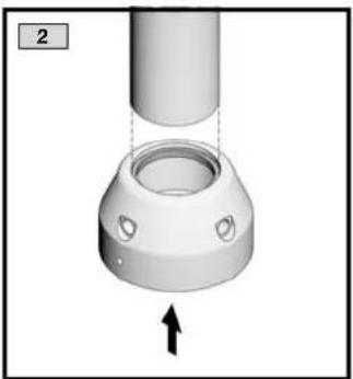
natural_image
3D rendering of a mechanical component with a conical base and mounting holes, showing an upward arrow (no text or symbols)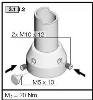
text_image
3.1 3.2 2x M10 x 12 M5 x 10 M₀ = 20 Nm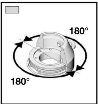
text_image
180° 180°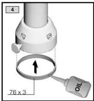
text_image
4 76 x 3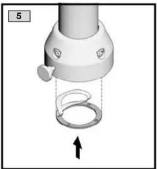
natural_image
3D rendering of a mechanical device with a curved ring and a handle, showing an upward arrow (no text or symbols)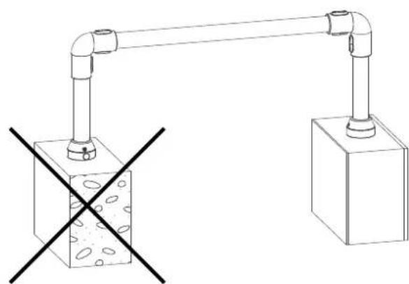
natural_image
Diagram of a mechanical linkage system with two blocks and a central cross symbol (no text or labels)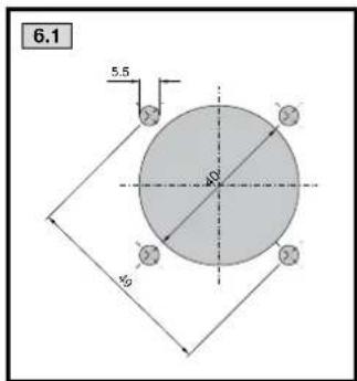
text_image
6.1 5.5 49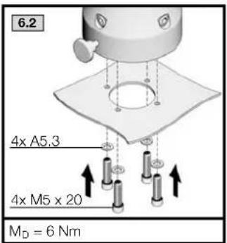
text_image
6.2 4x A5,3 4x M5 x 20 MD = 6 Nm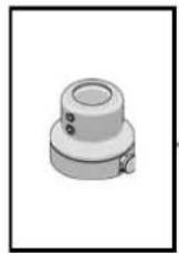


CP 6663.500
text_image
Exploded view diagram of a mechanical assembly with numbered components and directional arrows indicating movement or assembly.
text_image
1 48 x 4 oil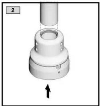
natural_image
3D rendering of a white mechanical component with a downward arrow indicator (no text or symbols)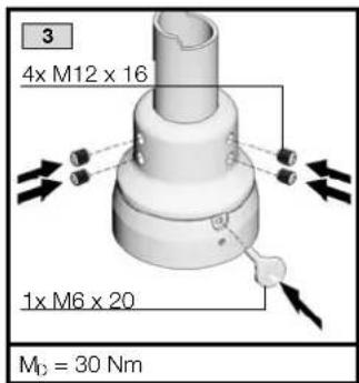
text_image
3 4x M12 x 16 1x M6 x 20 M₀ = 30 Nm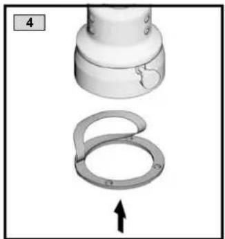
natural_image
Mechanical assembly diagram showing a cylindrical component and a ring with an arrow indicating motion (no text or symbols)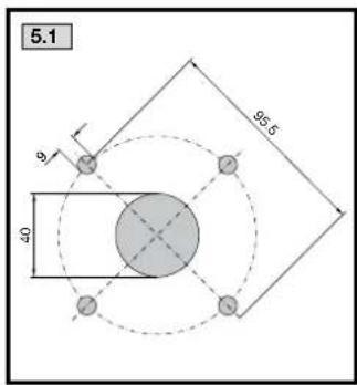
text_image
5.1 95.5 40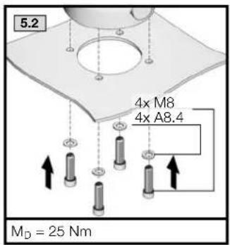
text_image
5.2 4x M8 4x A8.4 MD = 25 Nm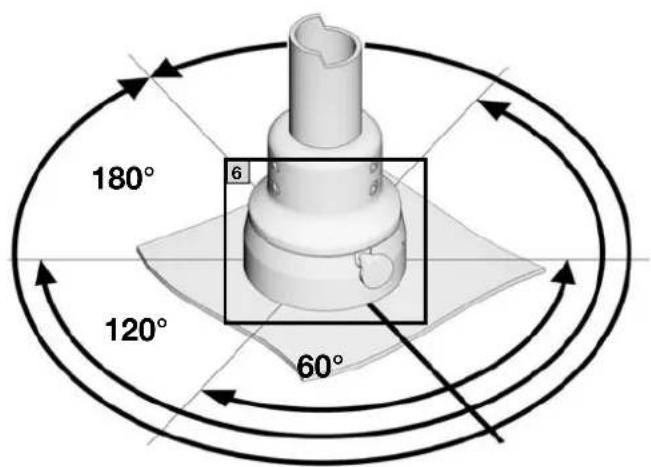
text_image
180° 6 120° 60°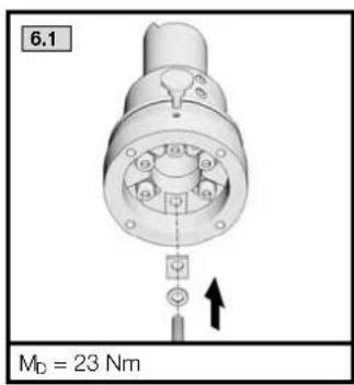
text_image
6.1 MD = 23 Nm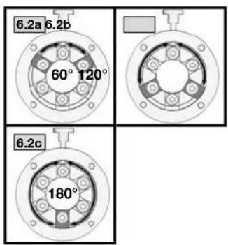
text_image
6.2a 6.2b 60° 120° 6.2c 180°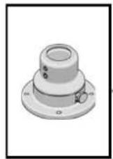

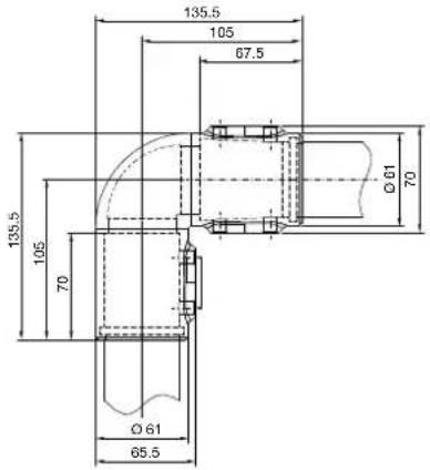
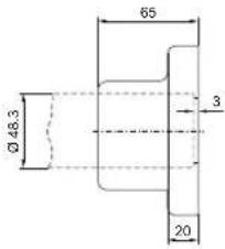
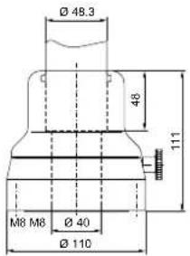
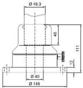
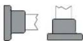
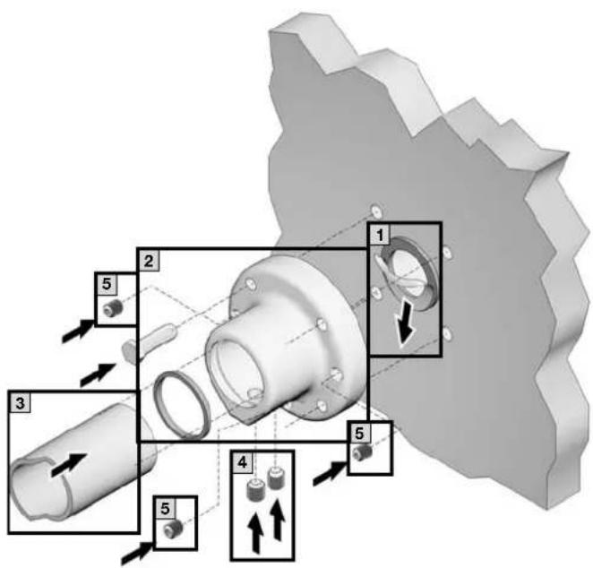
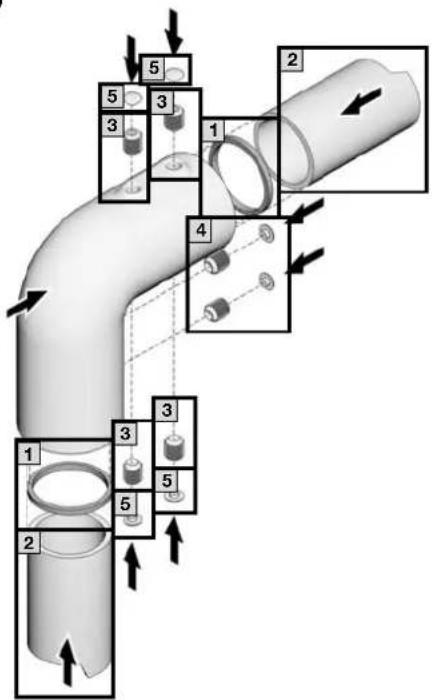
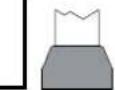
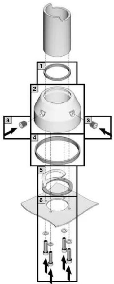
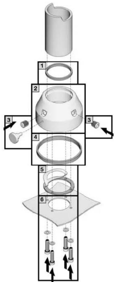
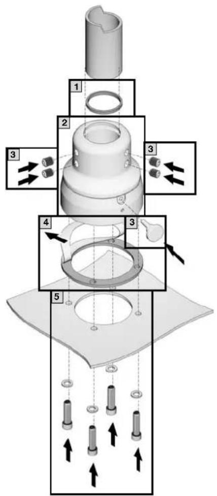
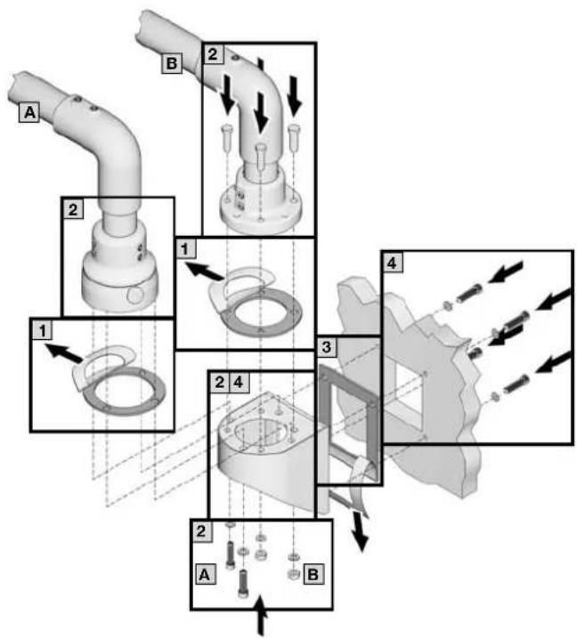
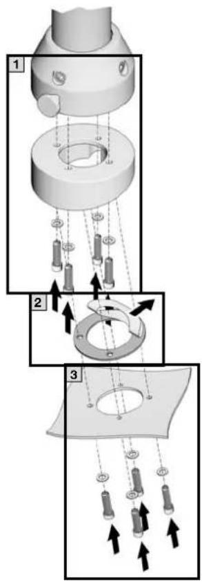
CP 6663.400
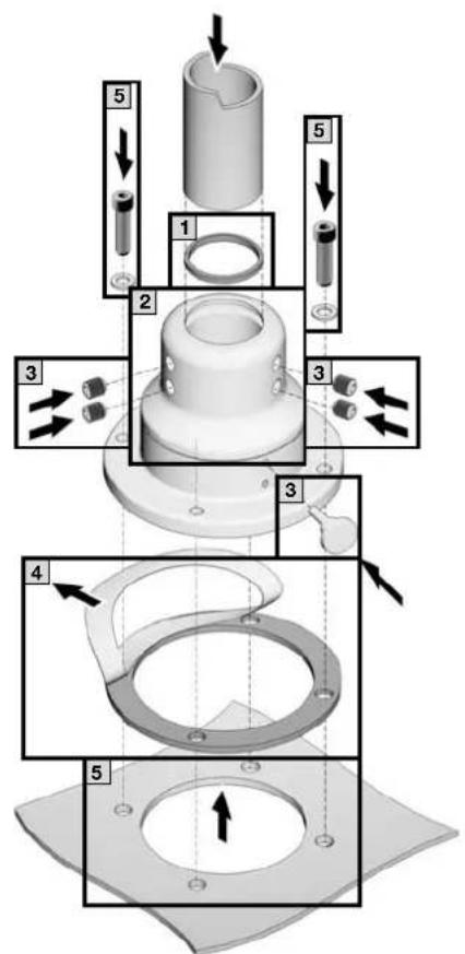
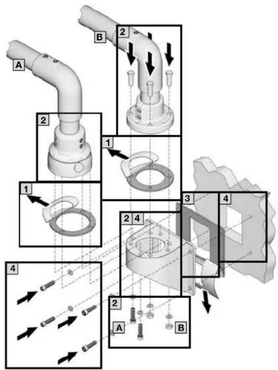
text_image
Technical diagram showing exploded view of a mechanical assembly with numbered components and directional arrows indicating assembly steps.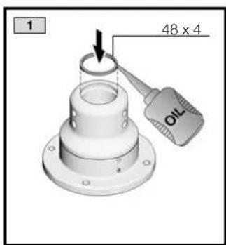
text_image
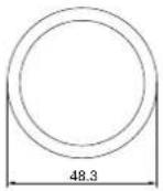
1 48 x 4 OIL
natural_image
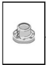
3D rendering of a mechanical component with a flanged base and bolted end, showing an upward arrow (no text or symbols)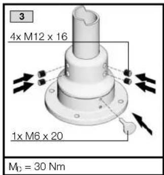
text_image
3 4x M12 x 16 1x M6 x 20 M₀ = 30 Nm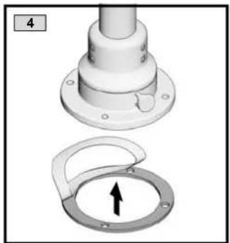
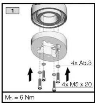
natural_image
Mechanical assembly diagram showing a flanged component and a circular ring with an arrow indicator (no text or symbols)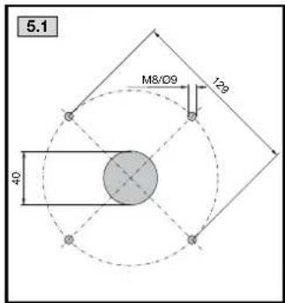
text_image
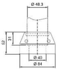
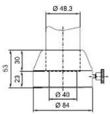
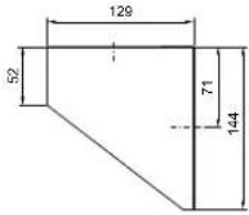
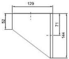
5.1 M8/D9 129 40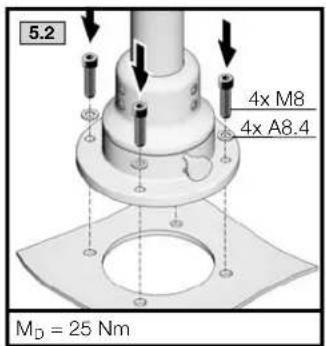
text_image
5.2 4x M8 4x A8.4 MD = 25 Nm
text_image
180° 6 120° 60°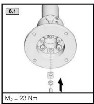
text_image
6.1 MD = 23 Nm
text_image
6.2a 6.2b 60° 120° 6.2c 180°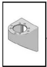
CP 6665.000
text_image
A 2 B 1 2 3 4 1 2 4 2 A B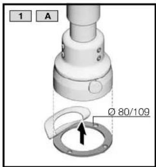
text_image
1 A Ø 80/109
text_image
1 B Ø 70/110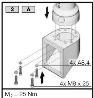
text_image
2 A 4x A8.4 4x M8 x 25 M0 = 25 Nm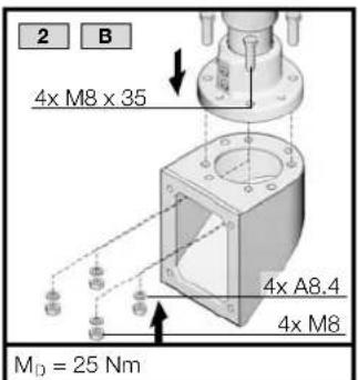
text_image
2 B 4x M8 x 35 4x A8.4 4x M8 MD = 25 Nm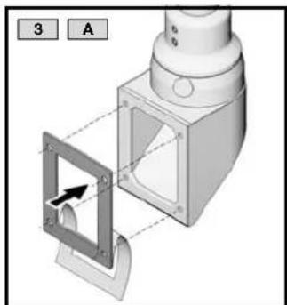
natural_image
3D mechanical assembly diagram showing a component with a highlighted square and arrow indicator (no text or symbols)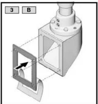
natural_image
3D mechanical assembly diagram showing a bracket with mounting holes and a highlighted square component (no text or symbols)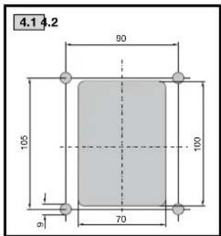
text_image
4.1 4.2 90 105 l 70 100 a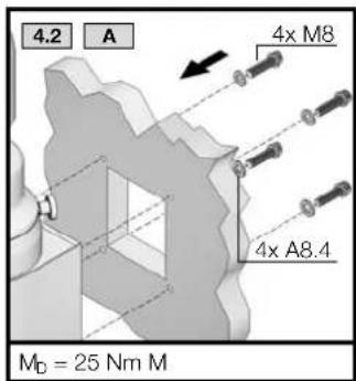
text_image
4.2 A 4x M8 4x A8.4 MD = 25 Nm M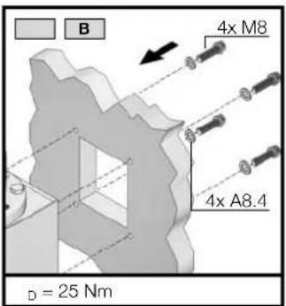
text_image
B 4x M8 4x A8.4 D = 25 Nm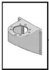


CP 6665.500
text_image
Technical diagram illustrating pipe fitting and mechanical assembly steps with labeled components A, B, 1-4
text_image
1 A Ø 80/109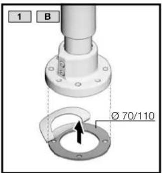
text_image
1 B Ø 70/110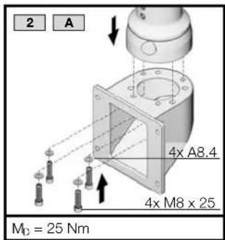
text_image
2 A 4x A8.4 4x M8 x 25 M0 = 25 Nm
text_image
2 B 4x M8 x 35 4x A8.4 4x M8 MD = 25 Nm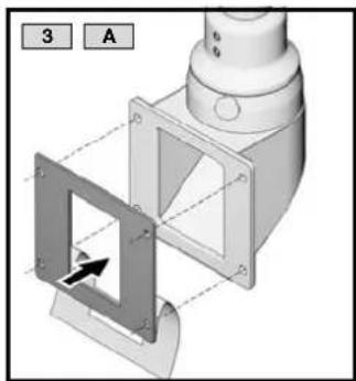
natural_image
3D mechanical assembly diagram showing a bracket with mounting holes and a highlighted square component (no text or symbols)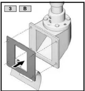
natural_image
3D mechanical assembly diagram showing a bracket with mounting flange and internal components, labeled with numbers 3 and B (no text or symbols on the diagram itself)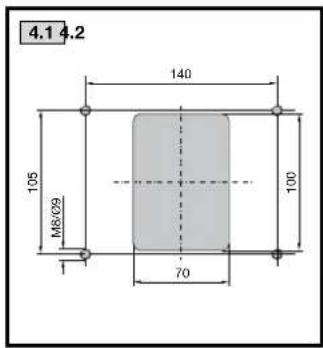
text_image
4.1 4.2 140 105 M8/09 100 70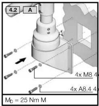
text_image
4.2 A 4x M8 4x 4x A8.4 4x MD = 25 Nm M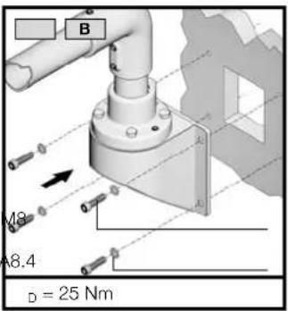
text_image
B M8 A8.4 D = 25 Nm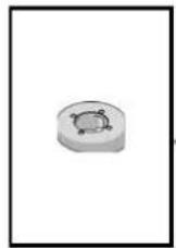
CP 6664.100
text_image
Technical diagram showing three-step assembly of a mechanical component with labeled parts and directional arrows indicating motion or movement.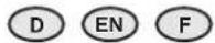
text_image
1 4x A5.3 4x M5 x 20 MD = 6 Nm
natural_image
Mechanical component diagram showing a valve assembly with a flange and internal components (no text or symbols)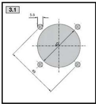
text_image
3.1 5.5 49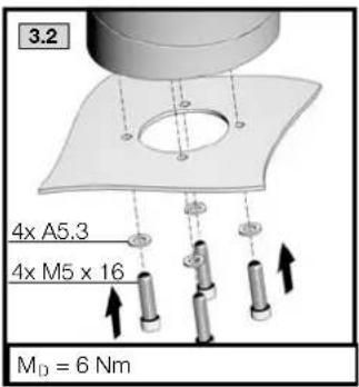
text_image
3.2 4x A5.3 4x M5 x 16 M_D = 6 Nm


| D | Zum Transport von vormontierten Tragarmsystemen sind geeignete Transportsicherungsmaßnahmen zu ergreifen! |
| EN | Pre-assembled support arm systems must be stabilised securely and protected appropriately for transportation! |
| F | Des mesures de sécurité adéquates doivent être prises pour le transport des bras porteurs pré-assemblés ! |
| E | ¡Deben tomarse las medidas de protección apropiadas para el transporte de los sistemas de brazo soportel! |
| I | Per il trasporto di sistemi a braccio portante premontati, sono necessarie adeguate misure di sicurezza. |
| NL | Voor het transport van vooraf gemonteerde draagarmsystemen dienen passende transportbeveiligingsmaatregelen genomen te worden! |
| S | Förmonterat bärarmssystem måste skyddas och stabiliseras på lämpligt sätt för säker transport! |
| J | 組立済みのサポートアームシステムを輸送する際は、適切な輸送対策を実施してください。 |
Rittal – The System.
Faster – better – everywhere.
■ Enclosures
■ Power Distribution
■ Climate Control
■ IT Infrastructure
■ Software & Services