TP 6742.500 - Armoire électrique Rittal - Notice d'utilisation et mode d'emploi gratuit
Retrouvez gratuitement la notice de l'appareil TP 6742.500 Rittal au format PDF.

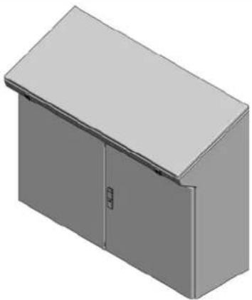
| Type de produit | Armoire électrique (pupitre monobloc) |
| Marque | Rittal |
| Modèle | TP 6742.500 |
| Utilisation | Montage et exploitation selon la notice |
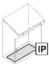
| Indice de protection IP | IP55 |
| Indice de protection IK | IK08 |
| Matériau | Tôle d'acier |
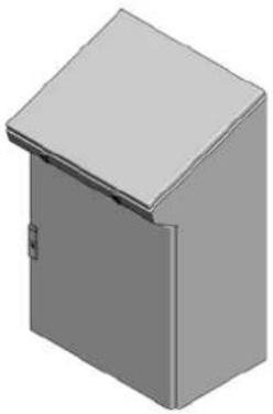
| Couleur | RAL 7035 (gris clair) |
| Dimensions approx. (L x P x H) | 600 x 500 x 1000 mm |
| Poids approx. | 50 kg |
| Fonctions principales | Protection des composants électriques, montage au sol |
| Montage | Sur pieds, avec accessoires de fixation |
| Entretien et nettoyage | Nettoyer avec un chiffon doux et sec |
| Sécurité | Attention : risque d'écrasement. Montage selon notice. |
| Pièces détachées | Disponibles chez Rittal (références sur catalogue) |
| Réparabilité | Composants remplaçables individuellement |
| Garantie | 2 ans (selon conditions Rittal) |
| Température de fonctionnement | -25°C à +55°C |
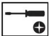
| Accessoires inclus | Vis de montage, clé de sécurité |
| Classe de protection | Classe I |
FOIRE AUX QUESTIONS - TP 6742.500 Rittal
Questions des utilisateurs sur TP 6742.500 Rittal
0 question sur cet appareil. Repondez a celles que vous connaissez ou posez la votre.
Poser une nouvelle question sur cet appareil
Téléchargez la notice de votre Armoire électrique au format PDF gratuitement ! Retrouvez votre notice TP 6742.500 - Rittal et reprennez votre appareil électronique en main. Sur cette page sont publiés tous les documents nécessaires à l'utilisation de votre appareil TP 6742.500 de la marque Rittal.
MODE D'EMPLOI TP 6742.500 Rittal
Rittal – The System.
Faster – better – worldwide.
text_image
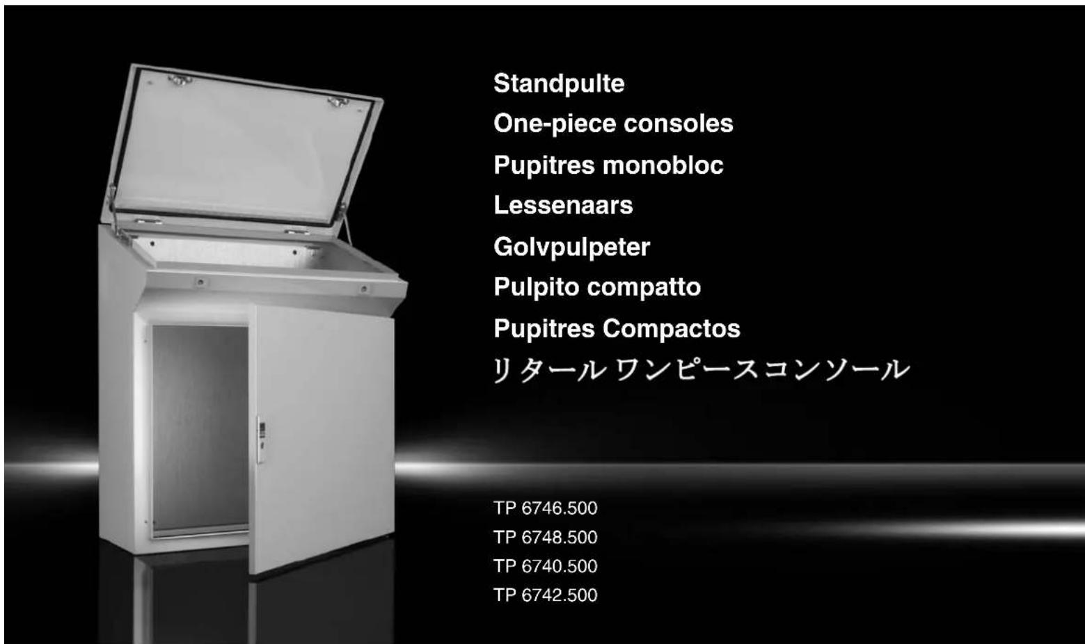
Standpulte One-piece consoles Pupitres monobloc Lessenaars Golvpulpeter Pulpito compatto Pupitres Compactos リタール ワンピースコンソール TP 6746.500 TP 6748.500 TP 6740.500 TP 6742.500Montage- und Bedienungsanleitung Assembly and operating instructions Notice de montage et mode d'emploi Montage- en bedieningshandleidning Montage- och bruksanvisning Istruzioni di montaggio e uso Instrucciones de montaje y empleo 取扱説明書

flowchart
graph LR
    A["ENCLOSURES"] --> B["POWER DISTRIBUTION"]
    B --> C["CLIMATE CONTROL"]
    C --> D["IT INFRASTRUCTURE"]
    D --> E["SOFTWARE & SERVICES"]
    E --> F["RITTAL"]

text_image
RITTAL
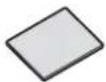
natural_image
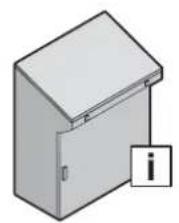
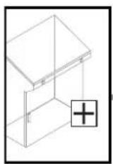
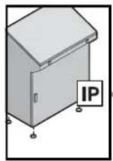
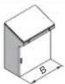
Illustration of a cabinet with a handle and a warning symbol (no text or labels)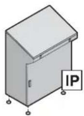
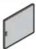
natural_image
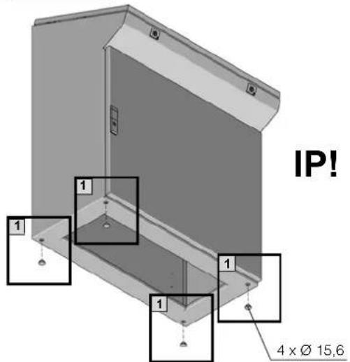
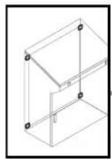
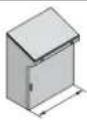
Isometric illustration of a cabinet with mounting feet and a label 'IP' (no text or symbols on the cabinet itself)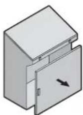
natural_image
3D diagram of a mechanical component with a rotating arrow indicating rotational motion (no text or symbols)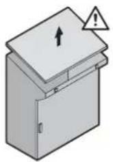
natural_image
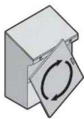
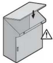
Illustration of a box with an open lid and warning symbol (no text or labels)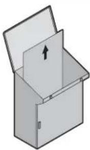
natural_image
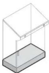
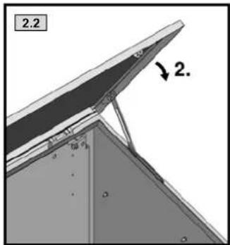
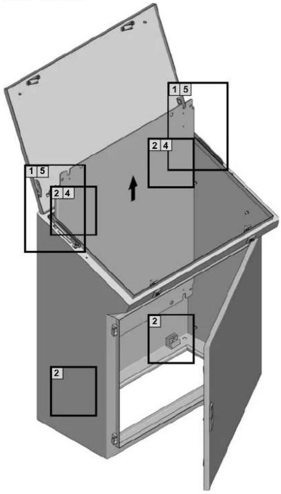
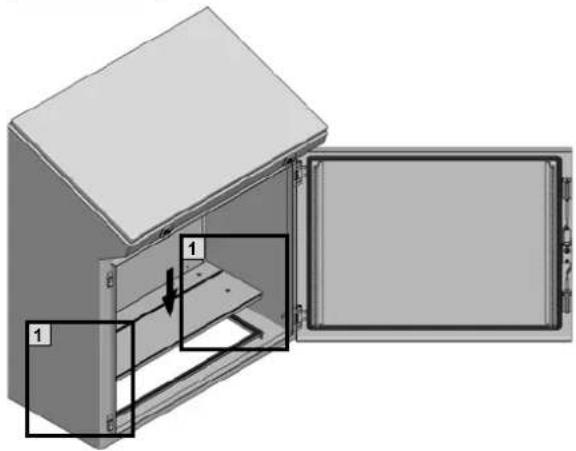
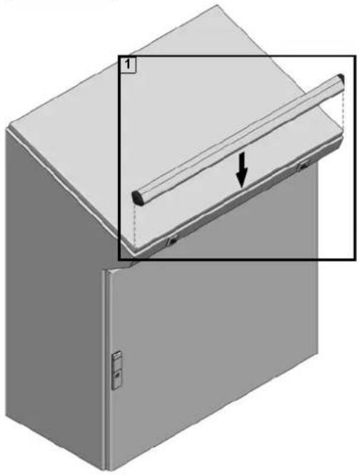
Illustration of an open storage cabinet with a directional arrow indicating upward movement (no text or symbols)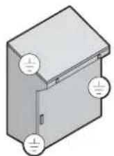
natural_image
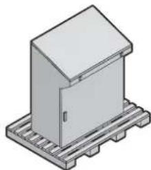
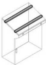
Isometric illustration of a rectangular enclosure mounted on a metal rack (no text or symbols)345/67
891819
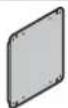
natural_image
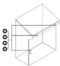
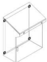
Isometric line drawing of a 3D mechanical or architectural component with mounting holes (no text or symbols)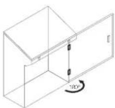
natural_image
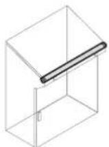
Isometric line drawing of a cabinet or enclosure with a 100-degree angle标注 (no text or symbols beyond the angle indicator)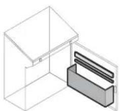
natural_image
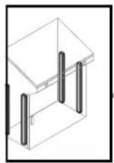
Isometric line drawing of a cabinet or storage unit with a highlighted internal panel (no text or symbols)10 11 12 13 14
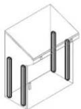
14 15 16 17
 |  | |||
| IP/IK 55/08 55/08 | ||||
 | 1 x 150 N stat. 1 x 150 N stat. | ### | ||
 | 1 x 200 N stat. | links/left: 130 N stat.rechts/right: 200 N stat. | ||
 | 1 x 1500 N stat. 1 x 1750 N stat. | ### | ||
 | 1 x 1 x | 12 | ||
| ### | ∅ 15,6 4 x 4 x | 4 | ||
 | M6 2 x 3 x | 9 | ||
| ### | M8 x 30 1 x 1 x | 18 | ||
| M6 x 12 2 x 3 x | 18 | |||
 | ∅ 8,2 1 x 1 x | 18 | ||
| ∅ 6,1 2 x 3 x | 18 | |||
| ### | M8 3 x 4 x | 18 | ||
| M6 2 x 3 x | 18 | |||
| [WTG8] | A8,4 2 x 3 x | 18 | ||
| A6,4 2 x 3 x | 18 | |||
 | A8 2 x 3 x | 18 | ||
| ### | 4 x 6 x | 18 | ||
text_image
IP! 1 1 1 1 4 x Ø 15,6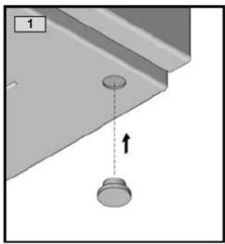
natural_image
Diagram showing a mechanical component with a downward arrow and a circular feature, no text or symbols present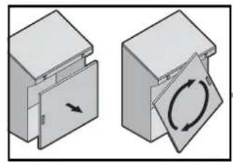
natural_image
Two 3D mechanical components with arrows indicating motion, one open and one closed, showing a circular arrow symbol (no text or labels)
natural_image
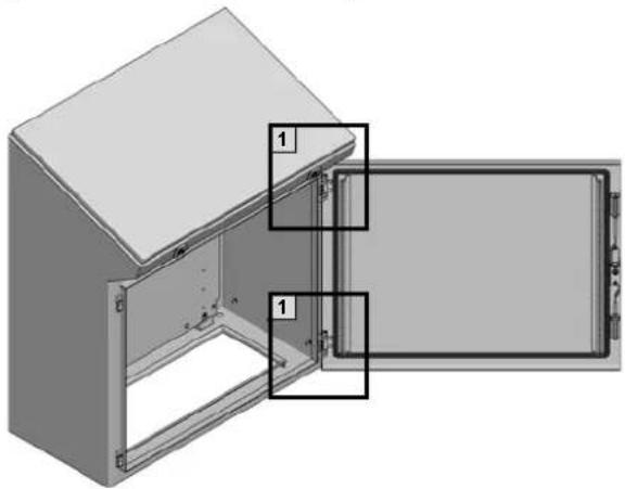
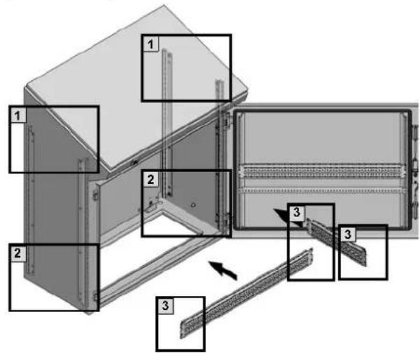
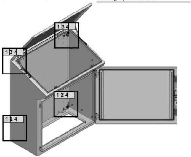
3D diagram of a cabinet with open door and labeled components (no text or symbols present)
text_image
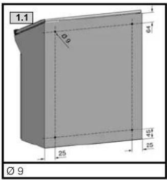
1.1 2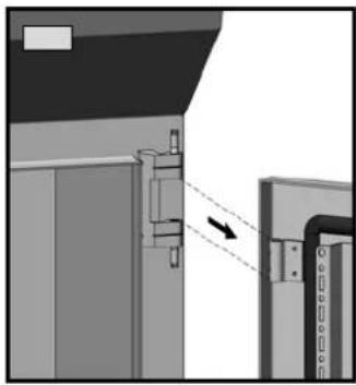
natural_image
Diagram showing a mechanical assembly with a dashed arrow indicating direction, no visible text or symbols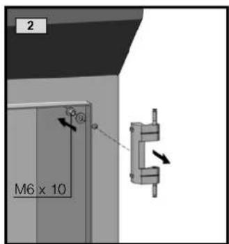
text_image
2 M6 x 10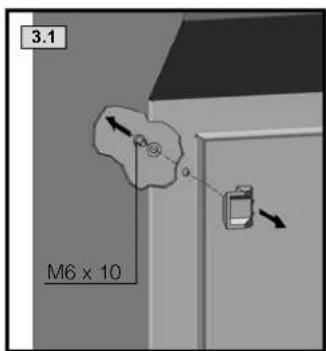
text_image
3.1 M6 x 10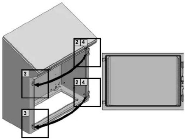
text_image
2 4 3 2 4 3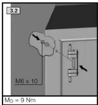
text_image
3.2 M6 x 10 MD = 9 Nm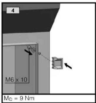
text_image
4 M6 x 10 MD = 9 Nm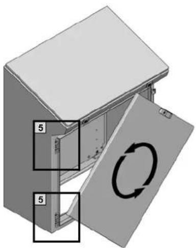
text_image
5 5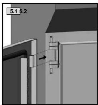
text_image
5.1 5.2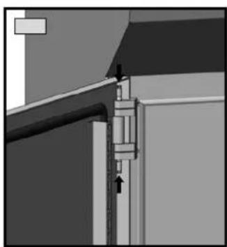
natural_image
Architectural detail showing a structural joint with arrows indicating force or movement (no text or symbols present)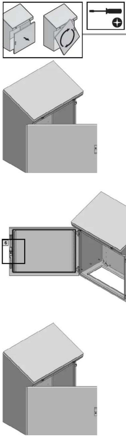
natural_image
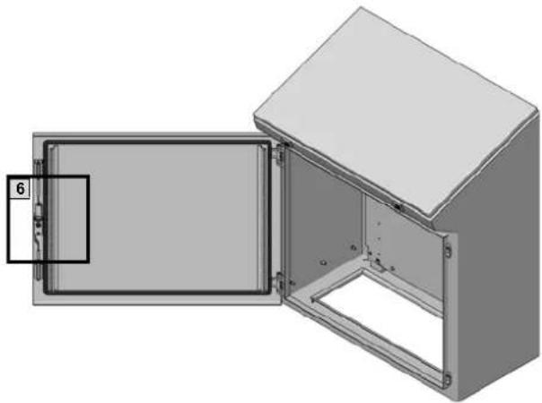
3D diagram of an open industrial enclosure with a labeled component (no text or symbols present)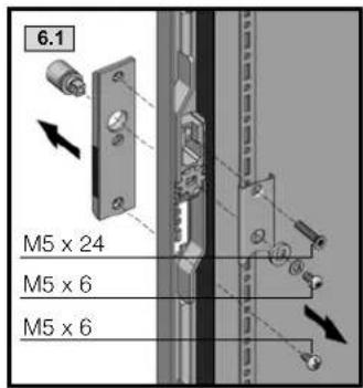
text_image
6.1 M5 x 24 M5 x 6 M5 x 6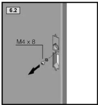
text_image
6.2 M4 x 8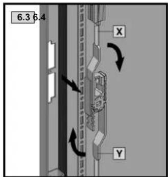
text_image
6.3 6.4 X Y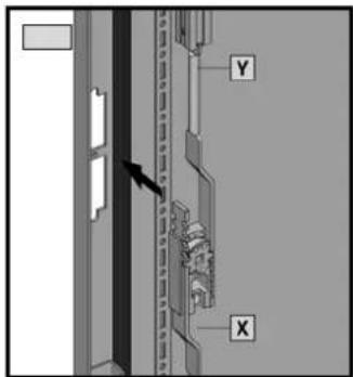
text_image
Technical diagram showing a door panel with labeled components X and Y, and an arrow pointing to a component.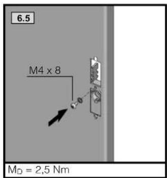
text_image
6.5 M4 x 8 MD = 2,5 Nm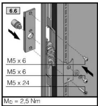
text_image
6.6 M5 x 6 M5 x 6 M5 x 24 MD = 2,5 Nm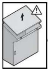


text_image
1 3 2 2 1 3 2 1 3 1 3 1 3 1 3 1 3 1 3 1 3 1 3 1 3 1 3 1 3 1 3 1 3 1 3 1 3 1 3 1 3 1 3 1 3 1 3 1 3 1 3 1 3 1 3 1 3 1 4 1 4 1 4 1 4 1 4 1 4 1 4 1 4 1 4 1 4 1 4 1 4 1 4 1 4 1 4 1 4 1 4 1 4 1 4 1 4 1 4 1 4 1 4 1 4 1 4 1 5 1 5 1 5 1 5 1 5 1 5 1 5 1 5 1 5 1 5 1 5 1 5 1 5 1 5 1 5 1 5 1 5 1 5 1 5 1 5 1 5 1 5 1 5 1 5 1 5 1 6 1 6 1 6 1 6 1 6 1 6 1 6 1 6 1 6 1 6 1 6 1 6 1 6 1 6 1 6 1 6 1 6 1 6 1 6 1 6
natural_image
Close-up of a mechanical component with a lever and arrow indicator (no text or symbols)
natural_image
Mechanical assembly diagram showing a lever mechanism with no visible text or symbols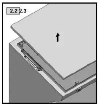
natural_image
3D diagram of a mechanical assembly with labeled parts and an arrow indicating direction (no text or symbols beyond labels)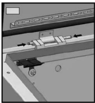
natural_image
Mechanical assembly diagram showing a sliding mechanism with arrows indicating motion (no text or symbols)
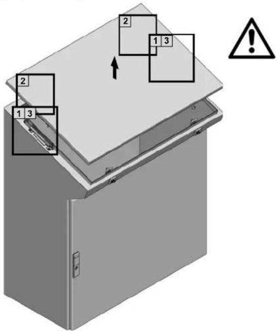
Achtung! Quetschgefahr.
Montage und Betrieb nur gemäß Anleitung.
Attention! Squeezing danger.
Assembly and operating only in accordance with operating manual.
natural_image
Mechanical assembly diagram showing a lever mechanism with a black arrow indicating direction (no text or symbols present)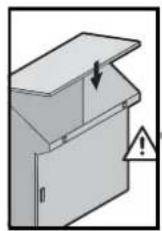

text_image
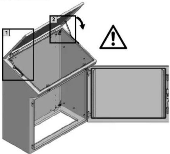
Diagram showing two labeled open doors with warning symbols and a warning triangle, likely illustrating a safety or hazard scenario.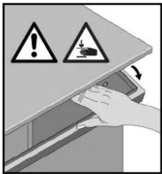
text_image
Warning symbol diagram showing warning signs with exclamation and dislocation arrows, indicating inspection or hazard zones.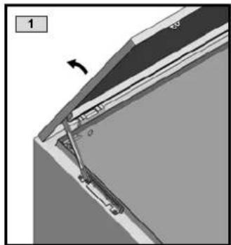
natural_image
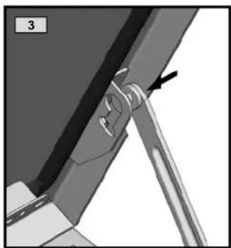
3D diagram of a structural joint or bracket with an arrow indicating direction (no text or symbols present)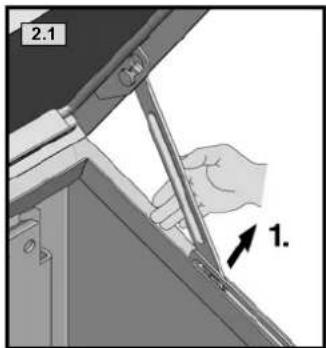
text_image
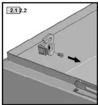
2.1 1.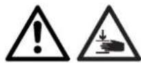
Achtung! Quetschgefahr.
Montage und Betrieb nur gemäß Anleitung.
Attention! Squeezing danger.
Assembly and operating only in accordance with operating manual.
text_image
2.2 2.
text_image
1 5 2 4 2 4 2 2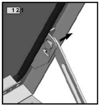
natural_image
Close-up of a mechanical component with a lever and arrow indicator (no text or symbols)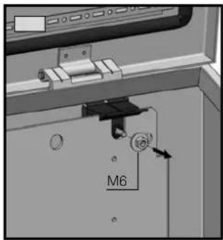
text_image
M6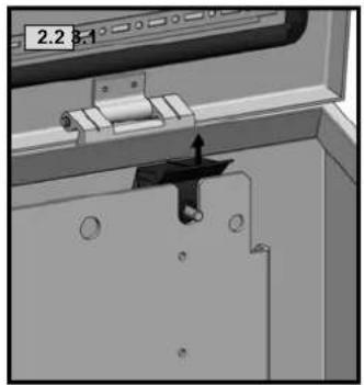
natural_image
Mechanical assembly diagram showing a bracket with mounting holes and a spring-loaded component (no text or symbols)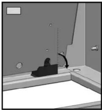
natural_image
Interior view of a bathroom sink with toilet and mirror (no text or symbols visible)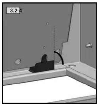
natural_image
Interior view of a bathroom sink with toilet and shower, showing no text or symbols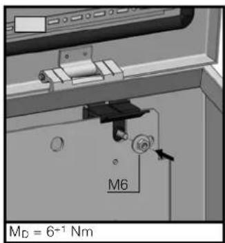
text_image
M6 MD = 6-1 Nm
natural_image
Mechanical assembly diagram showing a lever mechanism with a black arrow indicating motion direction (no text or symbols present)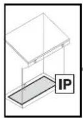
TX25 SW1


natural_image
3D diagram of an open electrical enclosure with labeled components (no text or symbols present)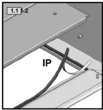
text_image
1.1 1.2 IP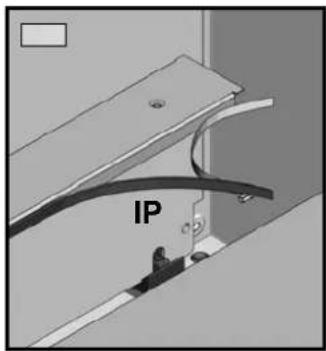
text_image
IP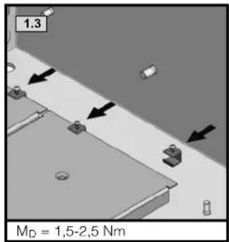
text_image
1.3 MD = 1,5-2,5 Nm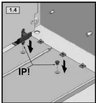
text_image
1.4 IP!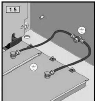
natural_image
Technical diagram of a mechanical assembly with labeled components (no readable text or symbols)
natural_image
Black-and-white collage showing various mechanical components and assembly views (no visible text or symbols)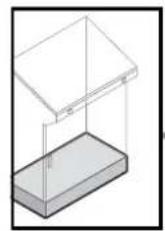
SW8

text_image
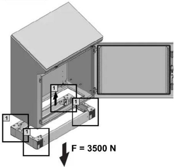
1 1 1 F = 3500 N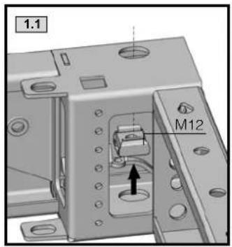
text_image
1.1 M12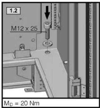
text_image
1.2 M12 x 25 MD = 20 Nm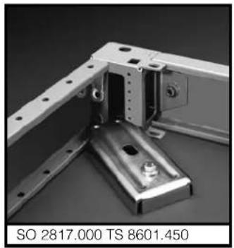
natural_image
Mechanical bracket assembly with metal components and mounting holes (no text or symbols visible)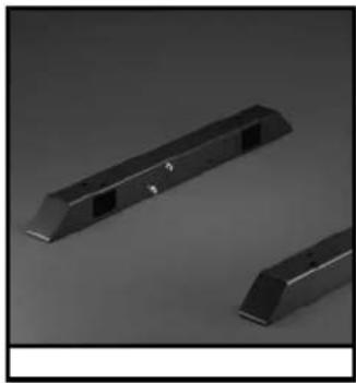
natural_image
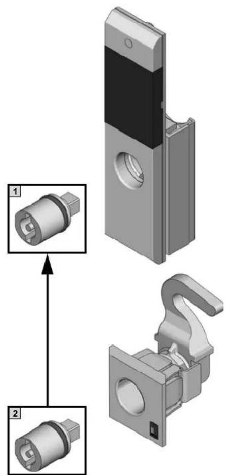
Two black plastic electronic components with slots and mounting holes, shown against a plain gray background (no text or symbols visible)
natural_image
3D mechanical assembly diagram showing two views of a component with internal parts, no text or symbols present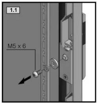
text_image
1.1 M5 x 6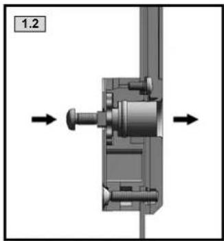
natural_image
Mechanical assembly diagram showing a bolted joint inserted into a housing, with directional arrows indicating movement (no text or symbols present)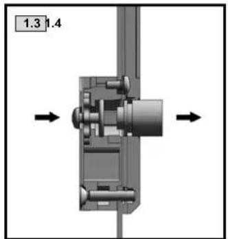
natural_image
Mechanical assembly diagram showing a shaft and housing with directional arrows (no text or symbols)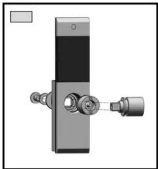
natural_image
Mechanical device with attached ports and a black panel (no visible text or symbols)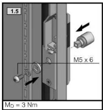
text_image
1.5 M5 x 6 MD = 3 Nm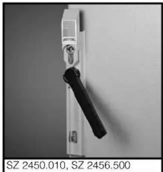
natural_image
Close-up of a white hand handle with black lever, mounted on a plain wall (no text or symbols visible)| 7 mm 2460.000 | |
| 8 mm 2461.000 | |
| 6,5 mm 2480.650 | |
| 7 mm 2462.000 | |
| 8 mm 2463.000 | |
| 2464.000 | |
| Daimler 2465.000 | |
| 3 mm 2466.000 | |
| Fiat 2307.000 |
natural_image
3D mechanical assembly diagram showing a clamp and mounting bracket with directional arrows (no text or symbols)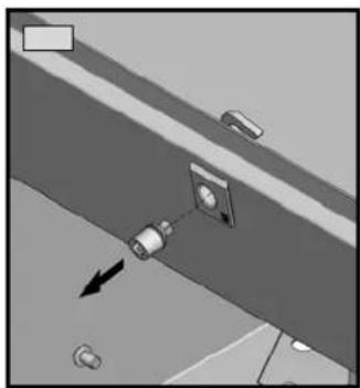
natural_image
Diagram of a mechanical assembly with directional arrows and components (no text or symbols)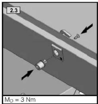
text_image
2.3 M_D = 3 Nm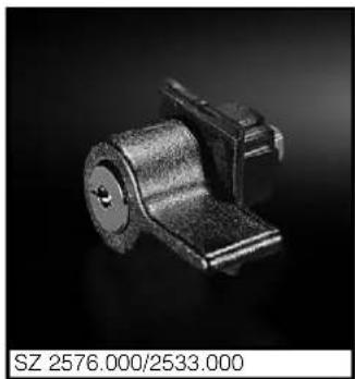
natural_image
Close-up of a metallic mechanical component with a cylindrical body and mounting bracket (no visible text or symbols)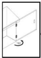
natural_image
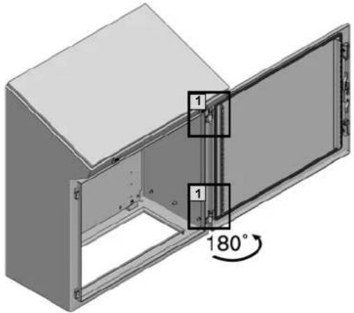
3D diagram of a cabinet or enclosure with labeled components and an 180° angle indicator (no text or symbols beyond basic geometry)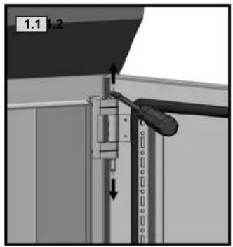
text_image
1.1 2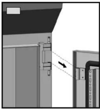
natural_image
Diagram showing a mechanical assembly with a dashed arrow indicating direction, no visible text or symbols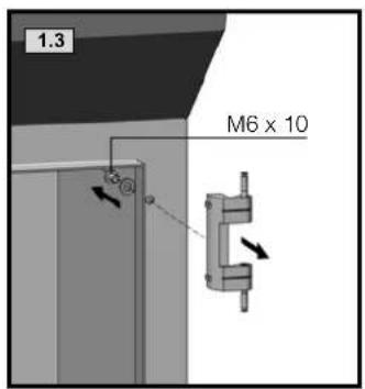
text_image
1.3 M6 x 10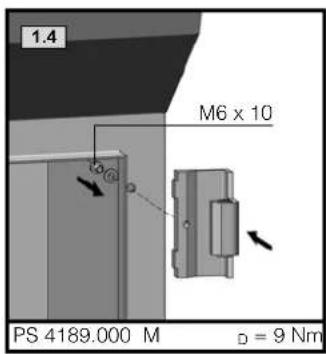
text_image
1.4 M6 x 10 PS 4189.000 M D = 9 Nm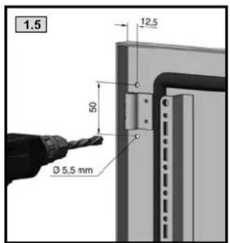
text_image
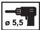
1.5 12.5 50 Ø 5,5 mm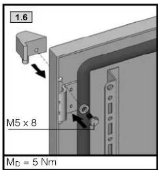
text_image
1.6 M5 x 8 MD = 5 Nm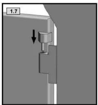
natural_image
Mechanical component with a downward arrow indicating a force or movement (no text or symbols present)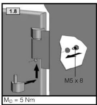
text_image
1.8 M_D = 5 Nm M5 x 8
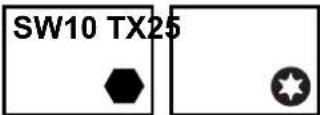
TX25

text_image
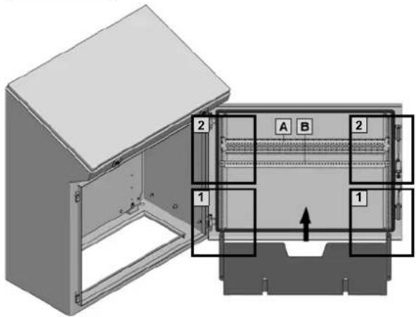
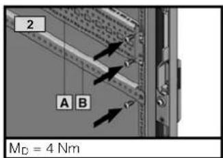
Technical diagram of a device with labeled components and internal structure, showing two views (1 and 2) with annotations A and B.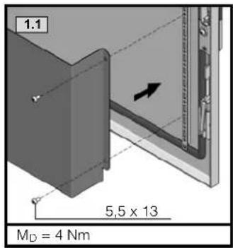
text_image
1.1 5,5 x 13 MD = 4 Nm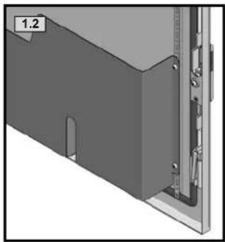
natural_image
3D mechanical part diagram showing a bracket with mounting holes and a close-up view of the side (no text or symbols)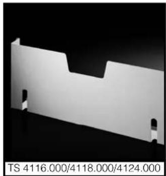
natural_image
Pure mechanical part diagram without any text, numbers, or symbols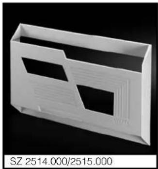
natural_image
White plastic enclosure with two cutouts and a side slot, displayed against black background (no text or symbols on the object itself)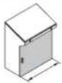 | |||
| 600/1200 800 1000 | |||
| A | 8612.050 | - | 8612.040 |
| B | 4596.000 4598.000 4309.000 | ||
text_image
2 A B M_D = 4 Nm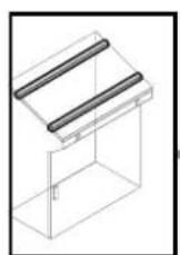
text_image
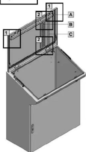
1 2 1 A B C 2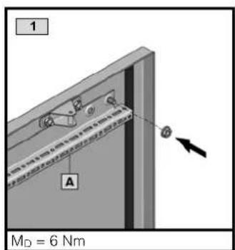
text_image
1 A M_D = 6 Nm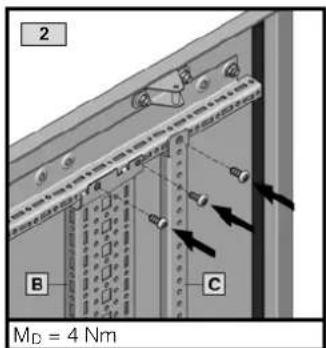
text_image
2 B C MD = 4 Nm| 600 800 1000 1200 | ||||
| A | 5001.050 5001.051 5001.052 | 5001.053 | ||
| B | 8612.040 | |||
| C | 4309.000 | |||
text_image
Technical diagram of a mechanical assembly with numbered components and directional arrows indicating assembly steps.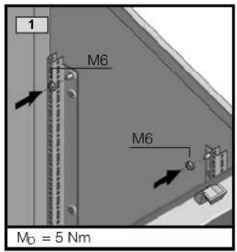
text_image
1 M6 M6 MD = 5 Nm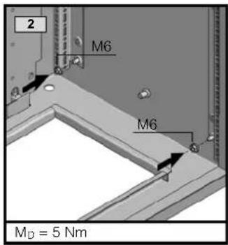
text_image
2 M6 M6 MD = 5 Nm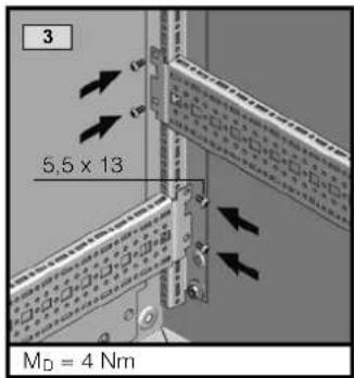
text_image
3 5,5 x 13 MD = 4 Nm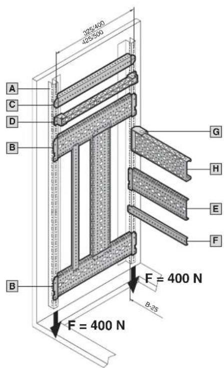
text_image
325/400 425/500 A C D B G H E F B F = 400 N B-25 F = 400 N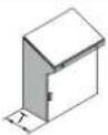 | ||||
| 400 | ||||
| A | 5001.051 | |||
| B | 8612.140 | |||
| C | 4694.000 | |||
| D | 4169.000 | |||
 | ||||
| 600 800 1000 1200 | ||||
| E | 8612.060 8612.080 8612.000 8612.020 | |||
| F | 8800.130 4579.000 -- | |||
| G | 8800.330 | |||
| H | 4376.000 | 4377.000 | 4378.000 | 4387.000 |
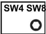
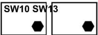
SW10 SW

13

[NO TEXT]
∅ 9
text_image
1 3 4 1 3 4 1 2 4 1 2 4CM 5001.075
Bei dynamischer Belastung
During dynamic load

text_image
1.1 Ø9 Ø4 Ø9 25 25 Ø9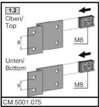
text_image
1.2 Oben/ Top 30 M8 Unten/ Bottom 20 M8 CM 5001.075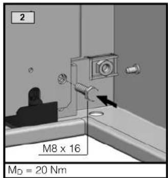
text_image
2 M8 x 16 MD = 20 Nm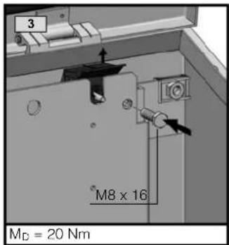
text_image
3 M8 x 16 MD = 20 Nm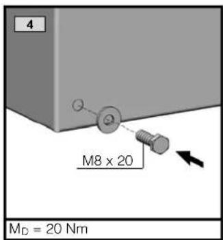
text_image
4 M8 x 20 MD = 20 Nm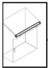
natural_image
3D diagram of a cabinet with an open lid and a diagonal tab, showing a cutaway view (no text or symbols)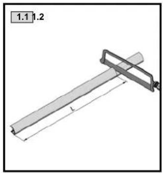
natural_image
Technical drawing of a mechanical lever assembly with labeled dimensions (no text or symbols beyond measurement markers)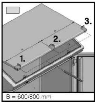
text_image
1. 2. 3. B = 600/800 mm
text_image
1.2 1. 2. 3. 4. 5. B = 1000/1200/1600 mm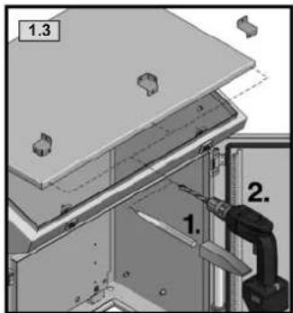
text_image
1.3 1. 2.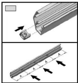
natural_image
Technical illustration of a mechanical component with arrows indicating assembly or movement (no text or symbols present)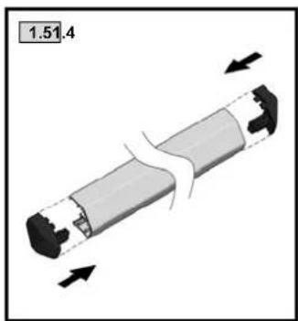
natural_image
Mechanical component diagram showing a cylindrical shaft with internal components and directional arrows indicating motion (no text or symbols)| Best.-Nr. | ||
| 600 573 | 6731.120 | |
| 800 | 773 | |
| 1000 973 | ||
| 1200 1173 |
text_image
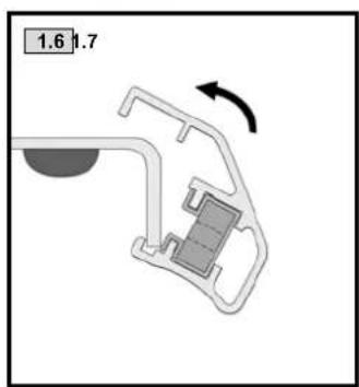
1.6 1.7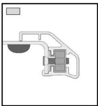
natural_image
Pure mechanical assembly diagram without any text, numbers, or symbols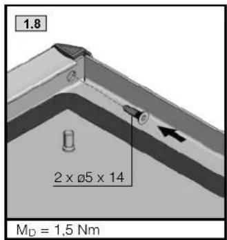
text_image
1.8 2 x Ø5 x 14 MD = 1,5 Nm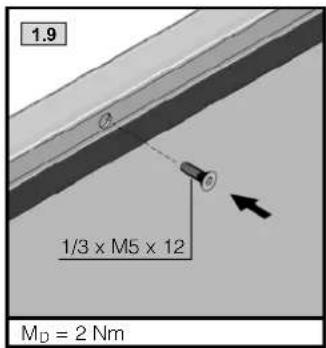
text_image
1.9 1/3 x M5 x 12 MD = 2 Nm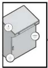
text_image
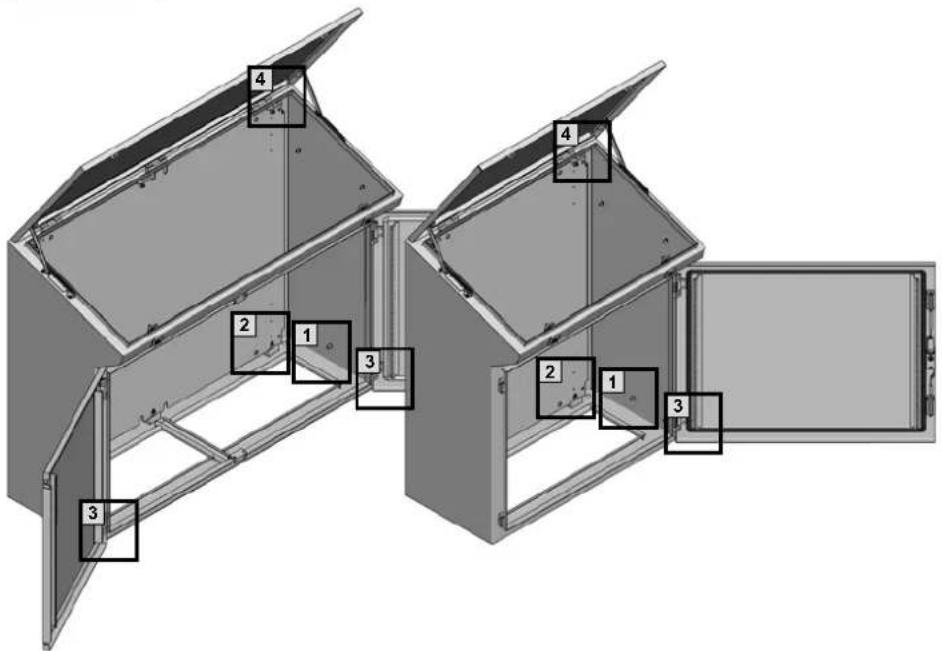
Technical diagram of a multi-compartment enclosure with numbered components, likely for architectural or engineering reference.2 I_in^2 × TK = 8.1 × 10^6 A^2S
text_image
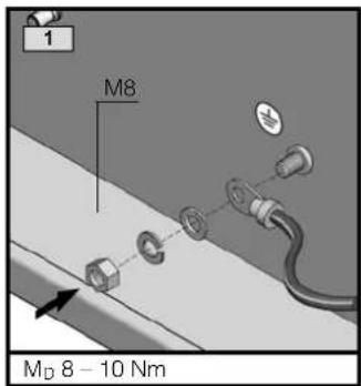
1 M8 MD 8 - 10 Nm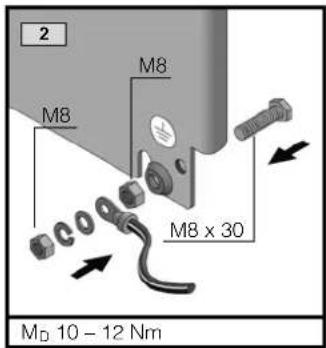
text_image
2 M8 M8 M8 x 30 MD 10 - 12 Nm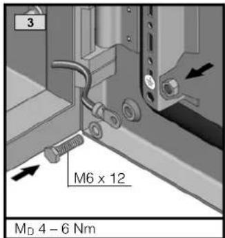
text_image
3 M6 x 12 MD 4 - 6 Nm| 1234 | |||||
| M6 x 30 1x | |||||
| M6 x 12 1x 1x | |||||
| ∅ 8,2 1x | |||||
| ∅ 6,1 1x 1x | |||||
| M8 1x 2x | |||||
| M6 1x 1x | |||||
| A 8,4 1x 1x | |||||
| A 6,4 1x 1x | |||||
| A 8 1x 1x | |||||
| 1x 1x 1x 1x |
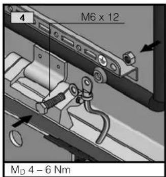
text_image
M6 x 12 M_D 4 - 6 Nm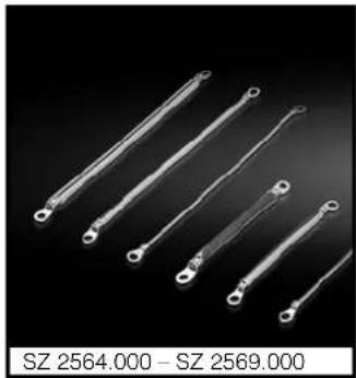
natural_image
Five metallic electrical terminals with terminal leads, displayed against a black background (no text or symbols on terminals)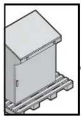


natural_image
3D rendering of a rectangular industrial enclosure with pallets and a lid, no visible text or symbols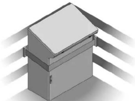
natural_image
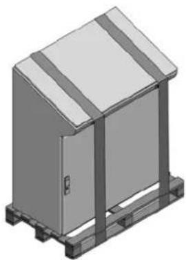
3D rendering of a cabinet with a lid and ventilation grilles (no text or symbols)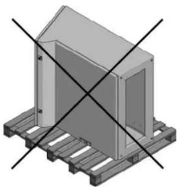
natural_image
3D diagram of a modular building on pallets with diagonal black lines indicating cross-section (no text or symbols)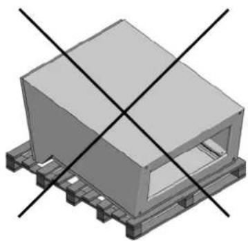
natural_image
3D rendering of a rectangular electronic component with mounting base and two intersecting black lines (no text or symbols)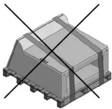
natural_image
3D mechanical component with intersecting diagonal lines (no text or symbols)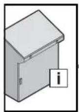
Qs [W]
 | ||||
| B 600 800 | 1000 1200 | |||
| W (Δ=20K) 227 | 277 328 378 | |||
Rittal – The System.
Faster – better – worldwide.
■Enclosures
■Power distribution
■Climate control
■IT infrastructure
■Software & services