TP 6700.500 - Armoire électrique Rittal - Notice d'utilisation et mode d'emploi gratuit
Retrouvez gratuitement la notice de l'appareil TP 6700.500 Rittal au format PDF.
| Type de produit | Armoire électrique (console) |
| Marque | Rittal |
| Modèle | TP 6700.500 |
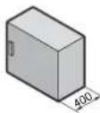
| Dimensions (L x P x H) | 600 x 400 x 400 mm (estimation) |
| Poids | Environ 25 kg (estimation) |
| Indice de protection | IP 55 (NEMA 12) |
| Résistance aux chocs | IK 08 |
| Température de fonctionnement | -20°C à +60°C (estimation) |
| Matériau | Acier laqué (estimation) |
| Couleur | RAL 7035 (gris clair, estimation) |
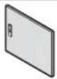
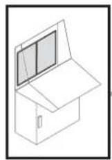
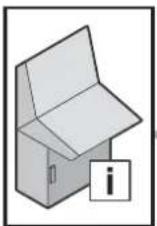
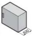
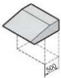
| Montage | Sur console (TopPult) ou au sol |
| Porte | Avec charnières et poignée (estimation) |
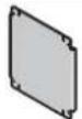
| Panneau de fixation | Oui, pour équipements 19" ou autres |
| Dissipation thermique maxi | Environ 120 W (pour largeur 600 mm, selon tableau) |
| Entretien et nettoyage | Nettoyer avec un chiffon doux et sec. Ne pas utiliser de produits abrasifs ou de solvants. |
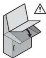
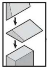
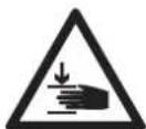
| Sécurité | Risque d'écrasement lors du montage. Suivre les instructions. |
| Pièces détachées et réparabilité | Portes, poignées, charnières, panneaux disponibles via Rittal. |
| Informations générales | Notice de montage et d'utilisation incluse. Système modulaire. |
FOIRE AUX QUESTIONS - TP 6700.500 Rittal
Questions des utilisateurs sur TP 6700.500 Rittal
0 question sur cet appareil. Repondez a celles que vous connaissez ou posez la votre.
Poser une nouvelle question sur cet appareil
Téléchargez la notice de votre Armoire électrique au format PDF gratuitement ! Retrouvez votre notice TP 6700.500 - Rittal et reprennez votre appareil électronique en main. Sur cette page sont publiés tous les documents nécessaires à l'utilisation de votre appareil TP 6700.500 de la marque Rittal.
MODE D'EMPLOI TP 6700.500 Rittal
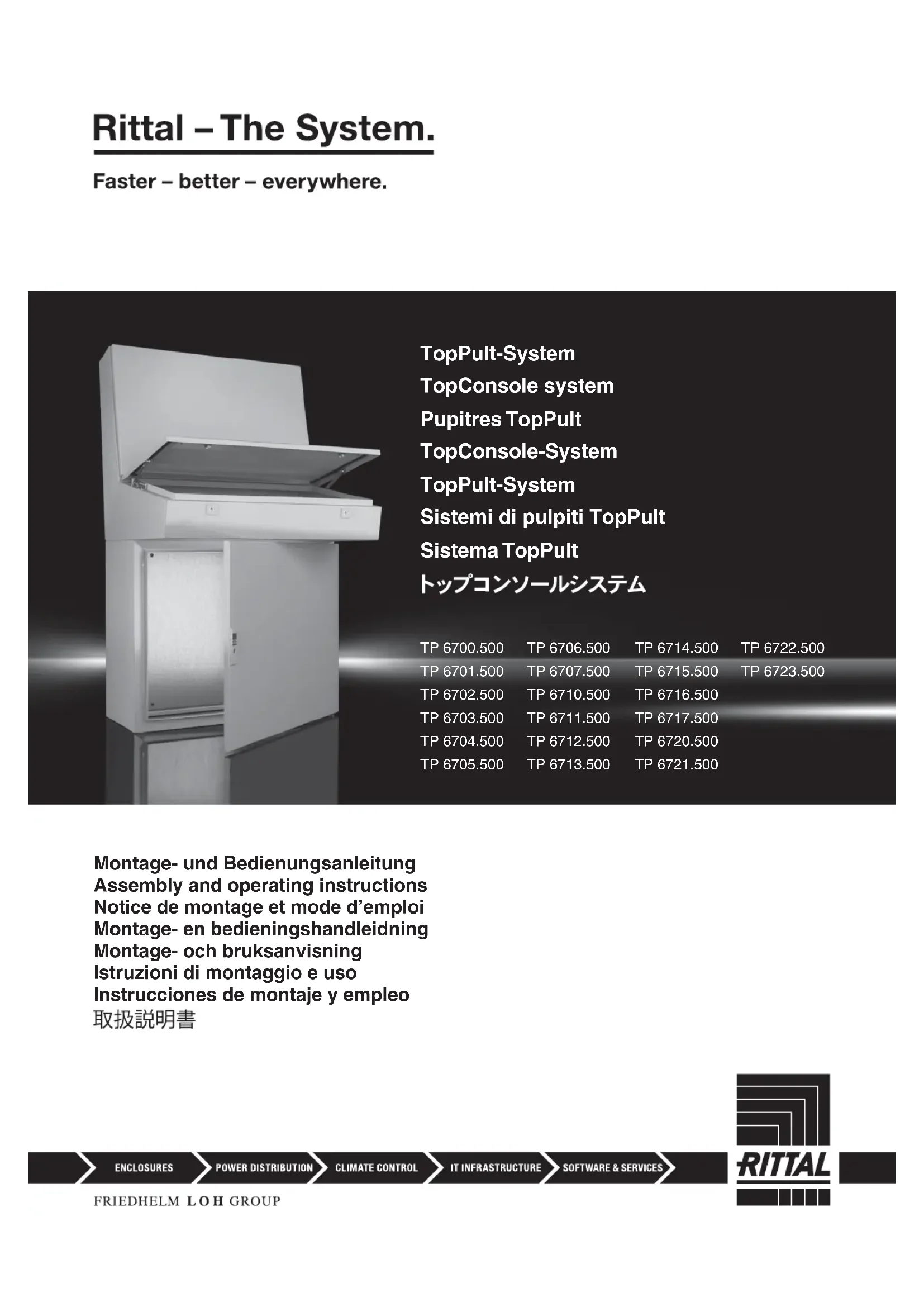
Rittal – The System.
Faster – better – everywhere.
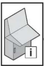
text_image
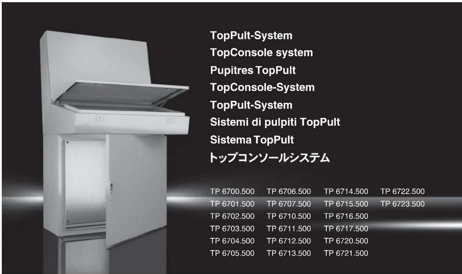
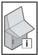
TopPult-System TopConsole system Pupitres TopPult TopConsole-System TopPult-System Sistemi di pulpiti TopPult Sistema TopPult トップコンソールシステム TP 6700.500 TP 6706.500 TP 6714.500 TP 6722.500 TP 6701.500 TP 6707.500 TP 6715.500 TP 6723.500 TP 6702.500 TP 6710.500 TP 6716.500 TP 6703.500 TP 6711.500 TP 6717.500 TP 6704.500 TP 6712.500 TP 6720.500 TP 6705.500 TP 6713.500 TP 6721.500Montage- und Bedienungsanleitung Assembly and operating instructions Notice de montage et mode d'emploi Montage- en bedieningshandleidning Montage- och bruksanvisning Istruzioni di montaggio e uso Instrucciones de montaje y empleo 取扱説明書

flowchart
graph LR
    A["ENCLOSURES"] --> B["POWER DISTRIBUTION"]
    B --> C["CLIMATE CONTROL"]
    C --> D["IT INFRASTRUCTURE"]
    D --> E["SOFTWARE & SERVICES"]
    E --> F["RITTAL"]
flowchart
graph TD
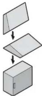
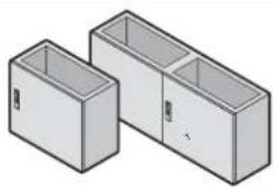
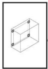
A["Rectangular Box"] --> B["Folded Box"]
B --> C["Final Box"]
natural_image
Isometric illustration of a cardboard box placed on a corrugated pallet (no text or symbols)9 10/11 21 22 23
12 13 14 15 16 16
17 18 19 20
 |  |  | |||||
| IP/UL 50 IP 55/Typ 12 (NEMA 12) IP 55/Typ 12 (NEMA 12) | |||||||
| IK 08 08 08 | |||||||
 |  |  | - | - | |||
 | - |  |  | ||||
 |  | - | - | ||||
 | 1 | x | 1 | 14 | |||
 | ∅9-2x2x | 5 | |||||
| ∅10-2x4x | 5 | ||||||
| ∅15,64x-- | 5 | ||||||
 | ∅6,14x1x1x | 21 | |||||
| ∅8,22x-- | 21 | ||||||
 | A8,13x2x2x | 21 | |||||
 | A6,44x1x1x | 21 | |||||
| A8,43x2x2x | 21 | ||||||
 | M6x12 | 4x1x1x | 21 | ||||
| M8x30 | 1x-- | 21 | |||||
 | 6x3x3x | 21 | |||||
 | M6 | 4x1x1x | 21 | ||||
| M8 | 4x2x2x | 21 | |||||
 | M8 | -4x8x | 4 | ||||
| [DD4S] | M8 | -8x | 16x | 4 | |||
| [SY6] | - | 2x | 2x | 4 | |||
| [47KS] | - | 1x | 1x | 4 | |||

text_image
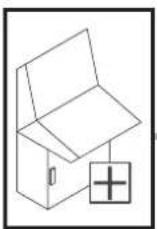
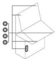
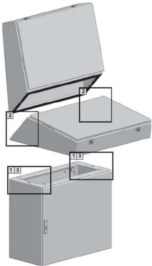
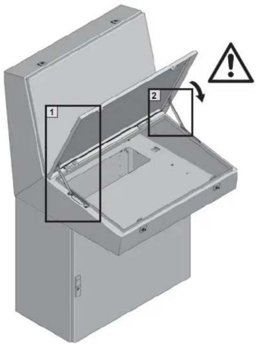
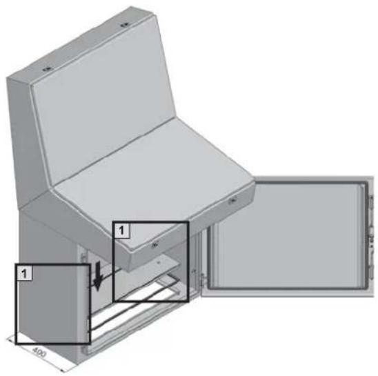
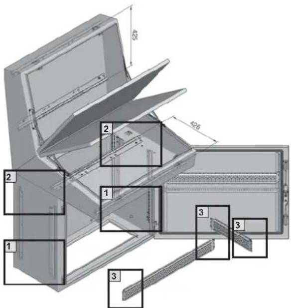
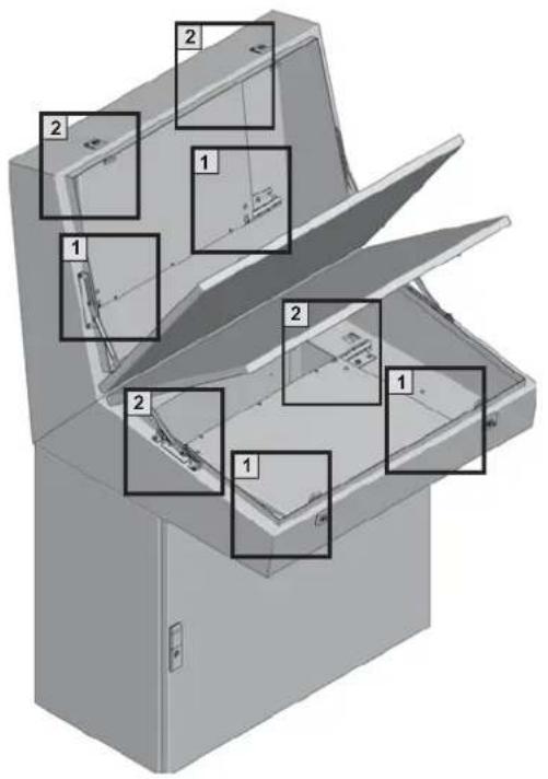
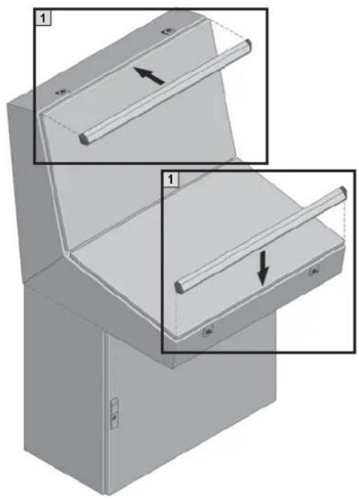
Technical diagram of an open refrigerator with numbered parts labeled 1, 2, and 3 for identification.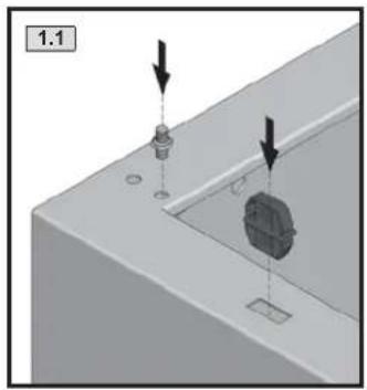
natural_image
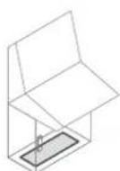
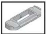
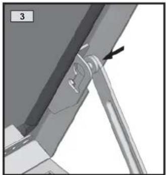
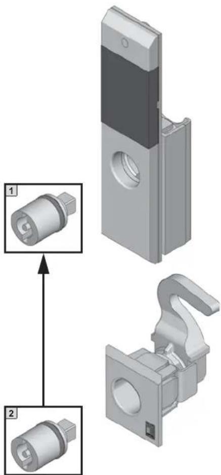
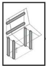
3D mechanical assembly diagram showing a component inserted into a housing with arrows indicating direction (no text or symbols)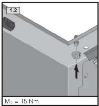
text_image
1.2 MD = 15 Nm
natural_image
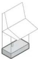
3D mechanical assembly diagram showing a bracket with mounting holes and a directional arrow (no text or symbols)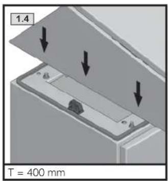
text_image
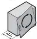
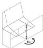
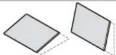
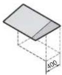
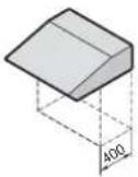
1.4 T = 400 mm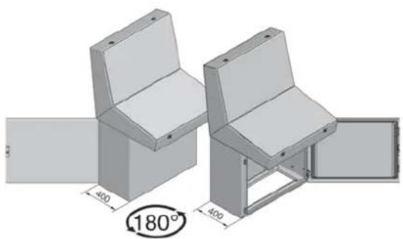
natural_image
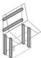
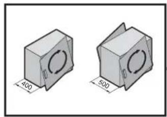
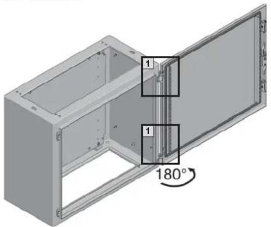
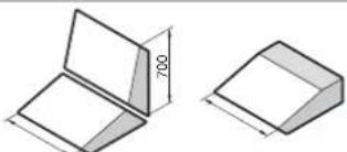
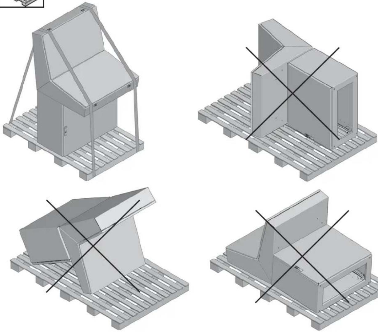
3D architectural rendering of two mechanical furniture units with dimension annotations (400x400) and a 180° angle label, no readable text or symbols beyond measurement markers.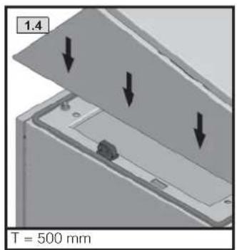
text_image
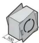
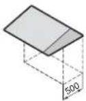
1.4 T = 500 mm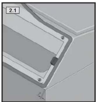
natural_image
3D mechanical part diagram showing a bracket with mounting holes and a central fastener (no text or symbols)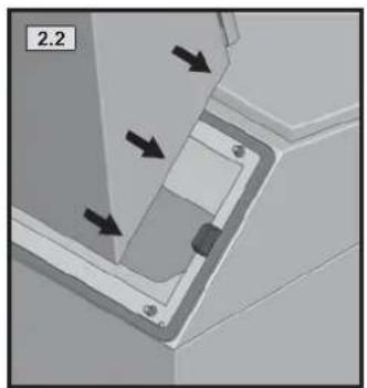
natural_image
Mechanical component diagram showing a bracket with arrows indicating force or movement (no text or symbols)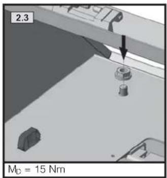
text_image
2.3 M_D = 15 Nm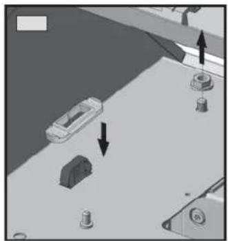
natural_image
Diagram showing a vehicle on a road with directional arrows indicating movement or force (no text or symbols present)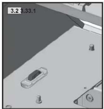
natural_image
3D rendered scene showing a car on a road with mechanical components and a scale marker (no readable text or symbols)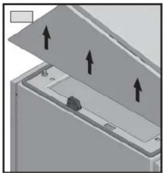
natural_image
Diagram of a device with three upward arrows indicating directional flow or movement, no text or symbols present1
1
2 × ∅ 9
2/4 × ∅ 10
IP!
2/4 × ∅ 10
4 × ∅ 15,6
SW4
1
1
M_D = 5 Nm
1
natural_image
Two 3D mechanical part diagrams with circular cutouts, each labeled with dimensions (400 and 500 units), no text or symbols present.
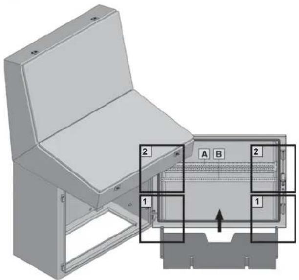
natural_image
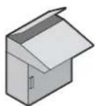
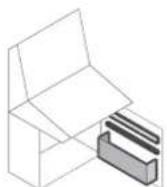
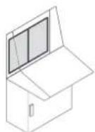
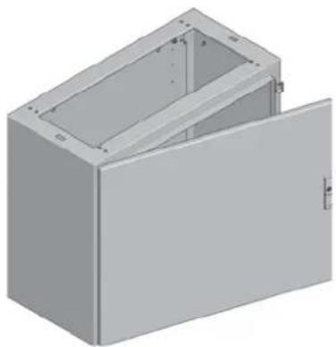
3D rendering of a gray open electrical cabinet or enclosure with internal compartments (no text or symbols visible)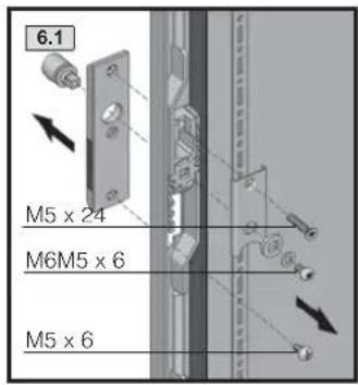
text_image
6.1 M5 x 24 M6M5 x 6 M5 x 6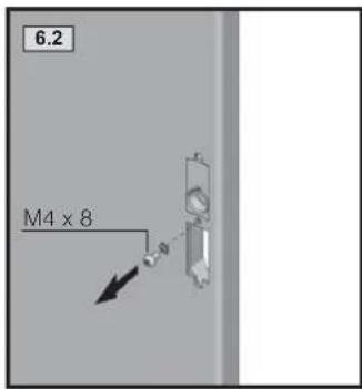
text_image
6.2 M4 x 8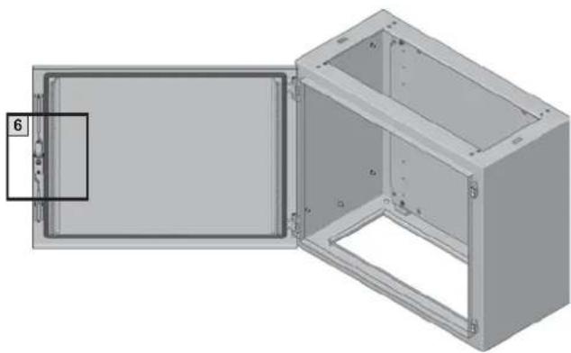
natural_image
3D diagram of an open industrial enclosure with a labeled component (no text or symbols present)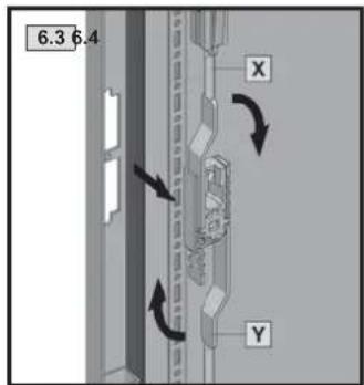
text_image
6.3 6.4 X Y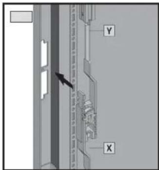
text_image
Diagram showing a door with labeled components Y and X, and an arrow pointing to a section of the door.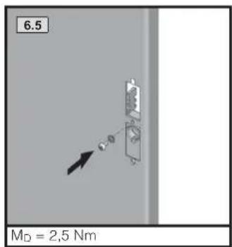
text_image
6.5 MD = 2,5 Nm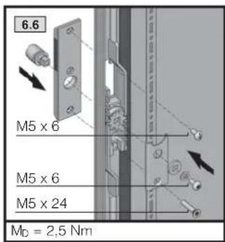
text_image
6.6 M5 x 6 M5 x 6 M5 x 24 MD = 2,5 Nm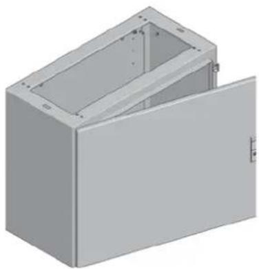
natural_image
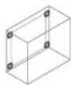
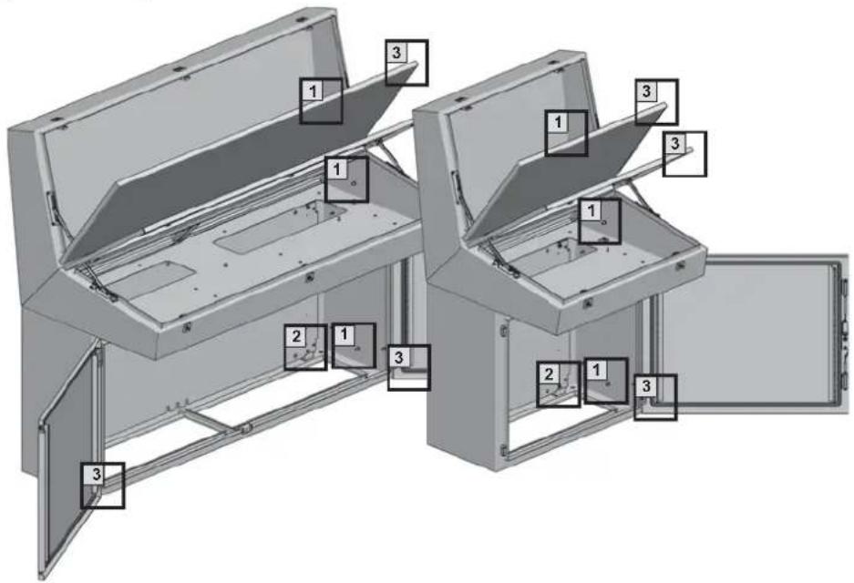
3D rendering of a gray rectangular cabinet with an open lid (no text or symbols visible)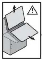

text_image
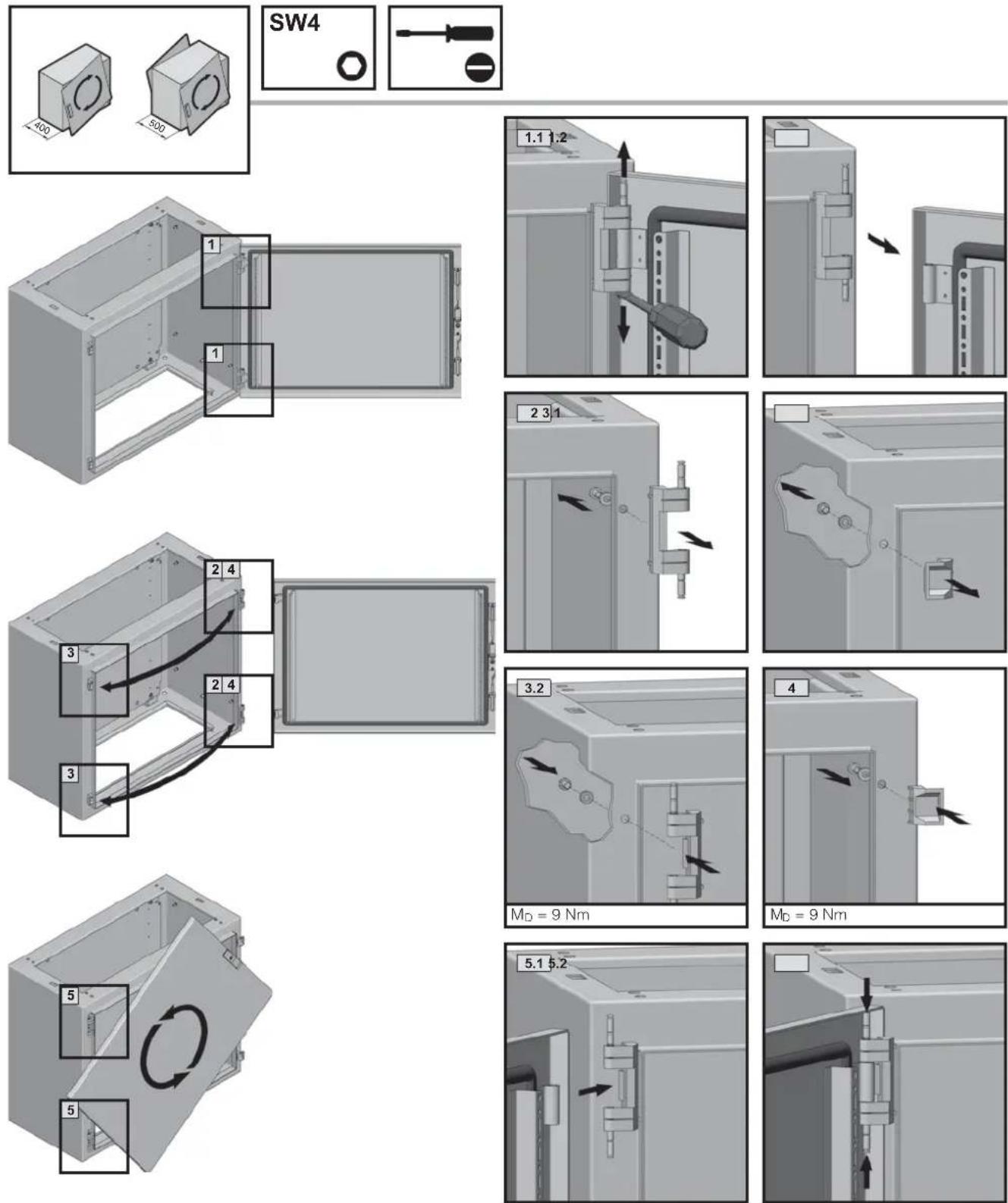
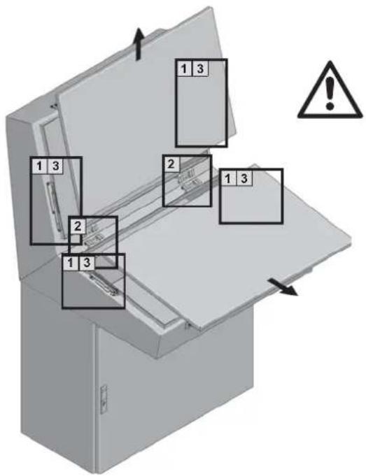
1 3 1 3 2 1 3 1 3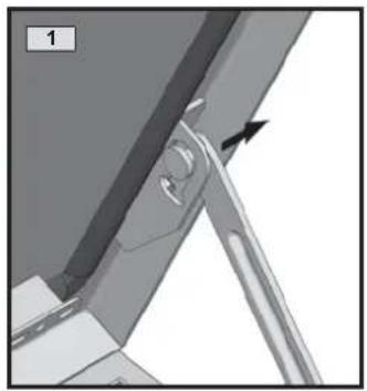
natural_image
Mechanical assembly diagram showing a bracket with a pin and a black arrow indicating direction (no text or symbols)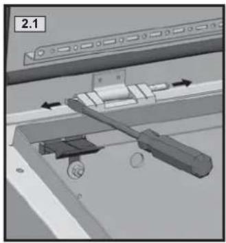
natural_image
Mechanical assembly diagram showing a lever mechanism with directional arrows and components (no readable text or symbols)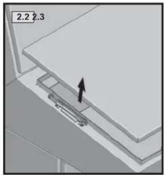
natural_image
3D mechanical assembly diagram showing a lever mechanism with an arrow indicating direction (no text or symbols)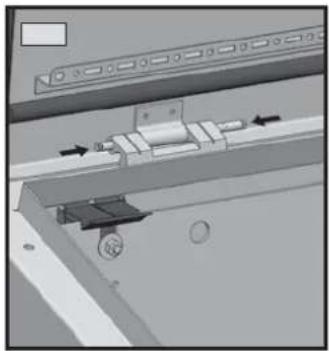
natural_image
Mechanical assembly diagram showing a sliding mechanism with arrows indicating motion (no text or symbols)
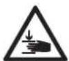
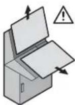
Achtung! Quetschgefahr.
Montage und Betrieb nur gemäß Anleitung.
Attention! Squeezing danger.
Assembly and operating only in accordance with operating manual.
natural_image
Mechanical assembly diagram showing a lever and pivot point with an arrow indicating direction (no text or symbols)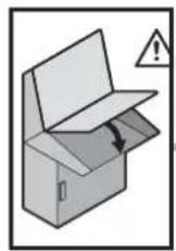

text_image
Diagram of an open electrical cabinet with labeled components and warning symbol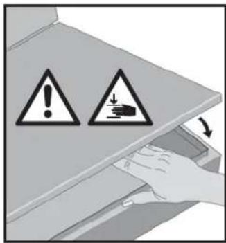
text_image
Warning symbol diagram showing warning signs for chemical hazard and waste disposal, with hand holding a container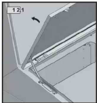
natural_image
Technical diagram of a mechanical assembly with no visible text or symbols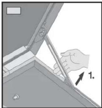
natural_image
Illustration of a hand using a tool to lift a component, labeled with number 1 (no text or symbols on the diagram itself)

Achtung! Quetschgefahr.
Montage und Betrieb nur gemäß Anleitung.
Attention! Squeezing danger.
Assembly and operating only in accordance with operating manual.
text_image
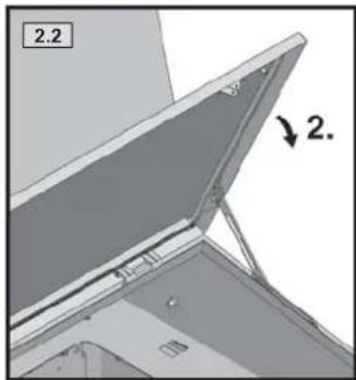
2.2 2.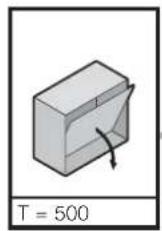
text_image
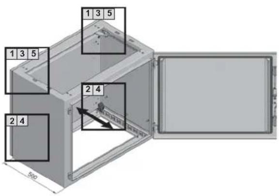
1 3 5 1 3 5 2 4 2 4 500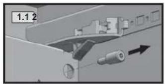
natural_image
Mechanical assembly diagram showing a component with a directional arrow (no text or symbols)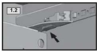
natural_image
Close-up of a mechanical component with an arrow indicating direction, no visible text or symbols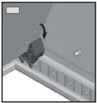
natural_image
3D diagram of a mechanical component with an arrow indicating rotation, no visible text or symbols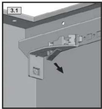
natural_image
Mechanical assembly diagram showing a bracket with a directional arrow indicating motion (no text or symbols present)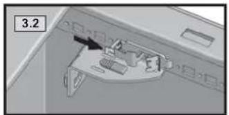
natural_image
Interior view of a room with furniture and a numbered label (3.2), no readable text or symbols present.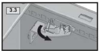
natural_image
Diagram showing a mechanical component with an arrow indicating rotational motion (no text or symbols present)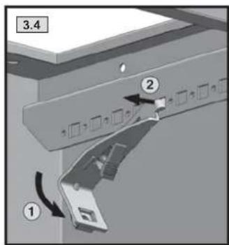
text_image
3.4 ① ②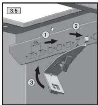
text_image
3.5 ① ② ③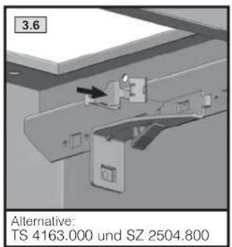
text_image
3.6 Alternative: TS 4163.000 und SZ 2504.800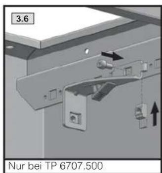
text_image
3.6 Nur bei TP 6707.500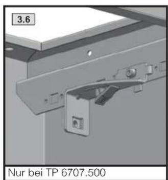
natural_image
Mechanical assembly diagram showing a bracket with mounting holes and a hanging component, labeled '3.6' and 'Nur bei TP 6707.500' (no readable text or symbols beyond labels)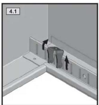
natural_image
3D diagram of a corner wall fixture with arrows indicating movement or force, no text or symbols present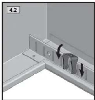
natural_image
3D diagram of a corner fixture with two arrows indicating movement or force, no text or symbols present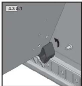
natural_image
Close-up of a mechanical component with a black knob and arrow indicating movement (no text or symbols)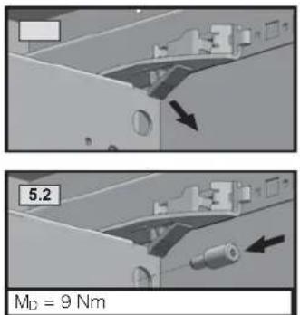
text_image
5.2 MD = 9 Nm

text_image
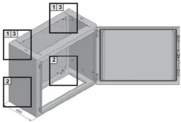
1 3 1 3 2 2 400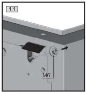
text_image
1.1 M6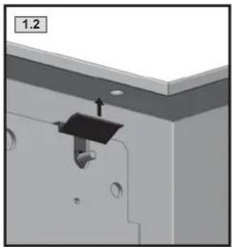
natural_image
3D mechanical assembly diagram showing a bracket with mounting holes and a central component (no text or symbols)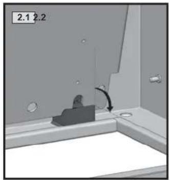
natural_image
Interior view of a room with a wall-mounted fixture and a curved arrow indicating rotation (no text or symbols)
natural_image
Interior view of a bathroom sink with toilet and bathtub (no text or symbols visible)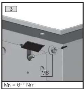
text_image
3 M6 MD = 6^-1 Nm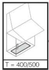

natural_image
3D diagram of a mechanical device with labeled components, showing internal structure and part layout (no text or symbols)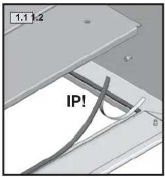
text_image
1.1 1.2 IP!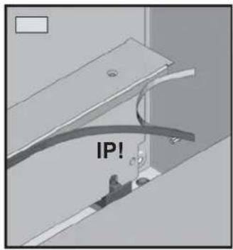
text_image
IP!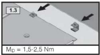
text_image
1.3 M_D = 1,5-2,5 Nm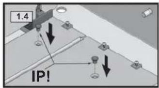
text_image
1.4 IP!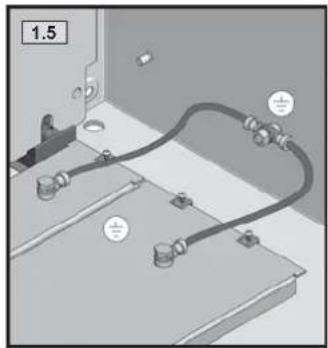
natural_image
Technical diagram of a mechanical assembly with labeled components (no readable text or symbols)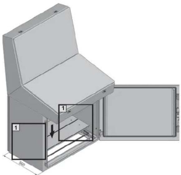
text_image
Technical diagram of a device with labeled components and dimension annotations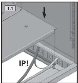
text_image
1.1 IP!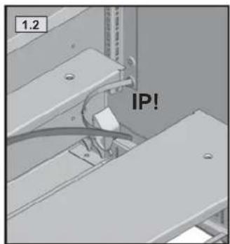
text_image
1.2 IP!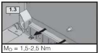
text_image
1.3 M_D = 1,5-2,5 Nm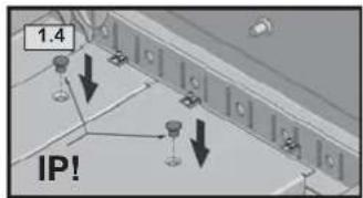
text_image
1.4 IP!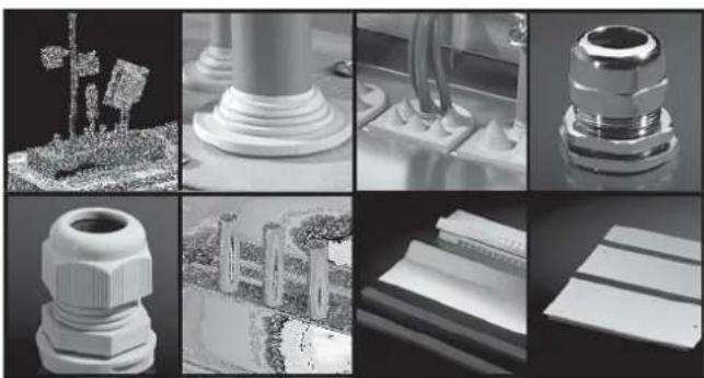
natural_image
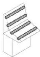
Grid of grayscale product images showing various mechanical components and surfaces, including a 3D-printed base, cylindrical components, and plastic caps (no text or symbols visible)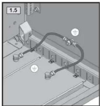
natural_image
Diagram of a mechanical or electrical component with labeled parts and wiring (no readable text or symbols)
SW8

text_image
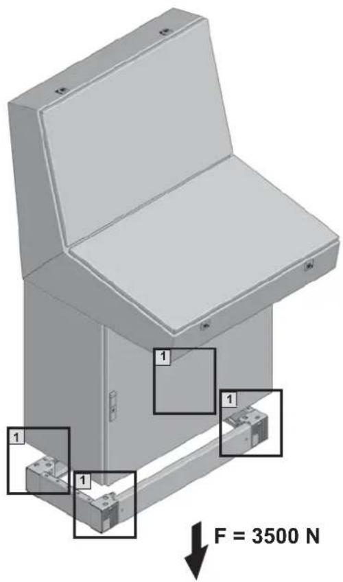
F = 3500 N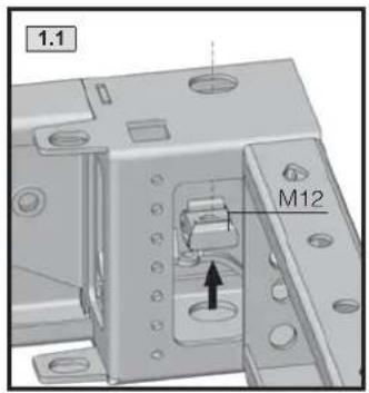
text_image
1.1 M12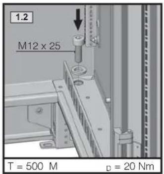
text_image
1.2 M12 x 25 T = 500 M D = 20 Nm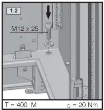
text_image
1.2 M12 x 25 T = 400 M D = 20 Nm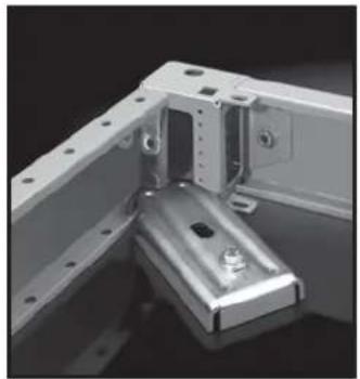
natural_image
Mechanical bracket assembly with metal components and mounting holes (no visible text or symbols)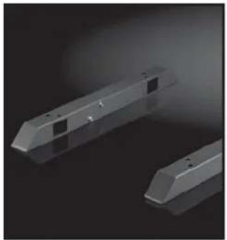
natural_image
3D rendered mechanical components with no visible text or symbols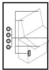
natural_image
3D mechanical assembly diagram showing two views of a component with internal parts, no text or symbols present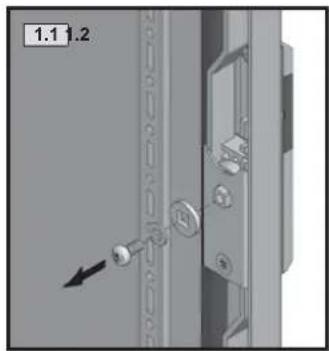
natural_image
Close-up of a door panel with lock and adjustment knob, no visible text or symbols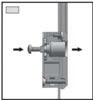
natural_image
Mechanical assembly diagram showing a shaft and housing with directional arrows indicating movement (no text or labels)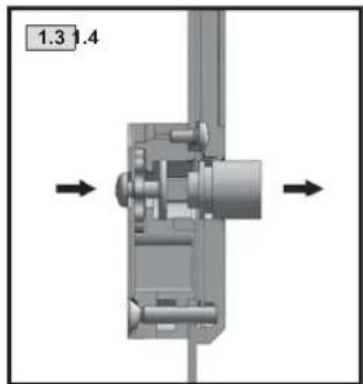
natural_image
Mechanical assembly diagram showing a shaft and housing with directional arrows indicating movement (no text or symbols)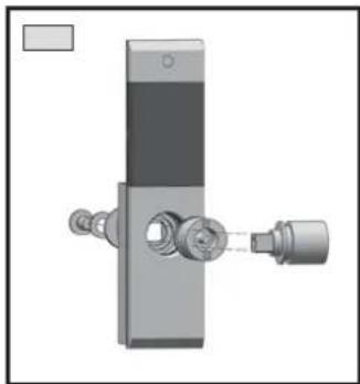
natural_image
Mechanical assembly diagram showing a vertical component with attached parts and a shaft (no text or symbols)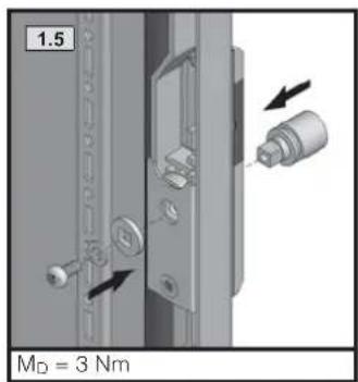
text_image
1.5 MD = 3 Nm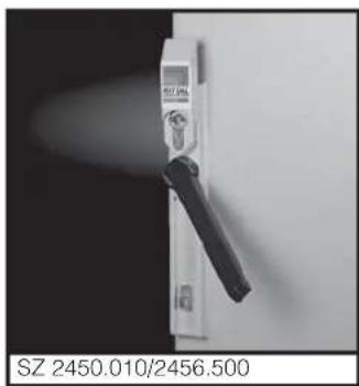
natural_image
Close-up of a white electrical switch with a black handle, mounted on a wall (no visible text or symbols)| 7 mm 2460.000 | |
| 8 mm 2461.000 | |
| 6,5 mm 2460.650 | |
| 7 mm 2462.000 | |
| 8 mm 2463.000 | |
| 2464.000 | |
| Daimler 2465.000 | |
| 3 mm 2466.000 | |
| Fiat 2307.000 |
natural_image
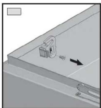
Mechanical assembly diagram showing a lock mechanism with a directional arrow (no text or symbols)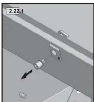
natural_image
Diagram showing a mechanical or electrical component with an arrow indicating direction, no readable text or symbols present.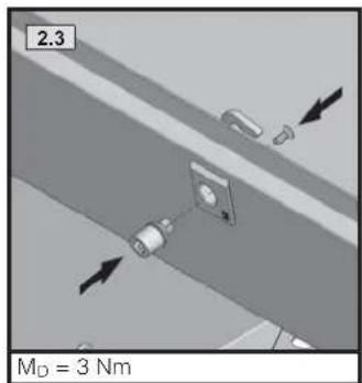
text_image
2.3 M_D = 3 Nm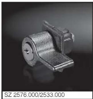
natural_image
Metal mechanical component with cylindrical body and flange, no visible text or symbols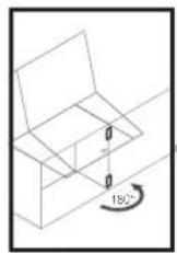
natural_image
3D technical diagram of a mechanical assembly with two labeled components and an 180° angle indicator (no text or symbols beyond labels)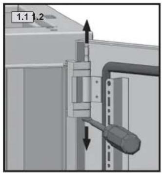
text_image
1.1 1.2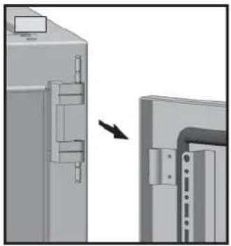
natural_image
Diagram showing a mechanical assembly with an arrow indicating a transformation or change (no text or symbols present)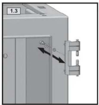
natural_image
Mechanical assembly diagram showing a door with arrows indicating movement or force, next to a bracket (no text or symbols present)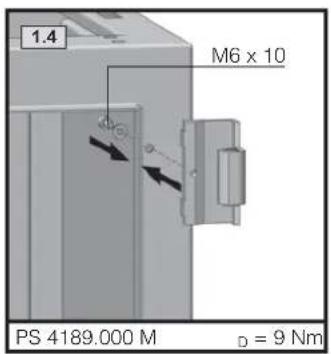
text_image
1.4 M6 x 10 PS 4189.000 M D = 9 Nm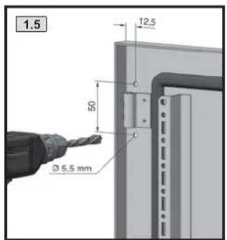
text_image
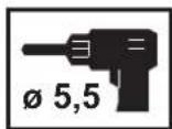
1.5 12.5 50 Ø 5.5 mm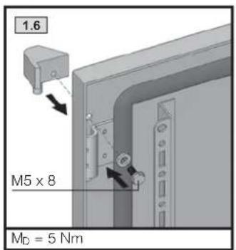
text_image
1.6 M5 x 8 MD = 5 Nm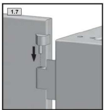
natural_image
Mechanical assembly diagram showing a component being inserted into a housing (no text or symbols visible)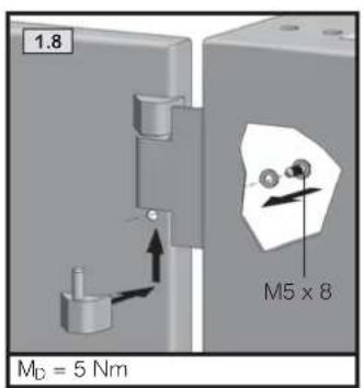
text_image
1.8 M_D = 5 Nm M5 x 8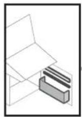
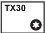
TX25

text_image
Technical diagram of a mechanical device with labeled components and directional arrows indicating assembly or movement.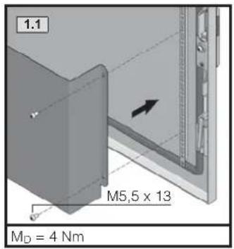
text_image
1.1 M5,5 x 13 MD = 4 Nm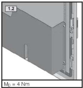
text_image
1.2 M_D = 4 Nm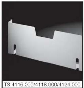
natural_image
White plastic sheet metal component with mounting holes, no text or symbols visible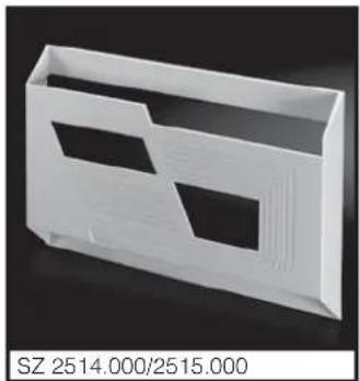
natural_image
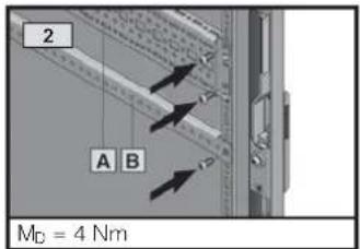
White plastic enclosure with two recessed cutouts, labeled SZ 2514.000/2515.000 (no other text or symbols visible)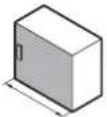 | ||
| 600/1200 800/1600 | ||
| A | 8612.050 - | |
| B | 4596.000 4598.000 | |
text_image
2 A B MD = 4 Nm
text_image
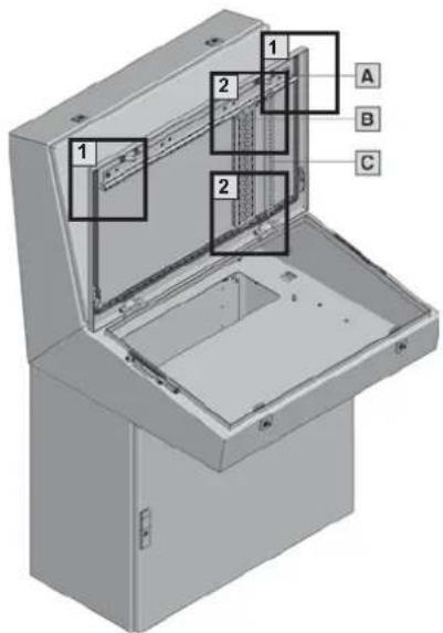
Technical diagram of an open electrical enclosure with labeled components and section views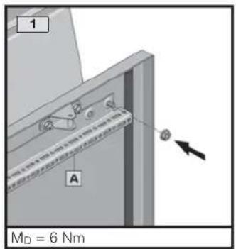
text_image
1 A MD = 6 Nm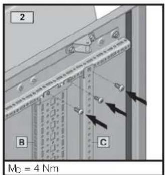
text_image
2 B C MD = 4 Nm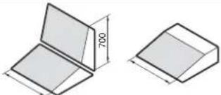 | ||||
| 600 800 1200 1600 | ||||
| A | 5001.050 5001.051 5001.053 5001.054 | |||
| B | 8612.040 | |||
| C | 4309.000 | |||
text_image
Technical diagram of a device with numbered components and dimension annotations in millimeters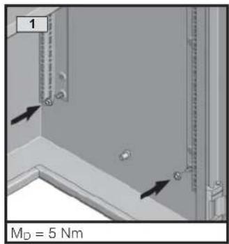
text_image
1 M_D = 5 Nm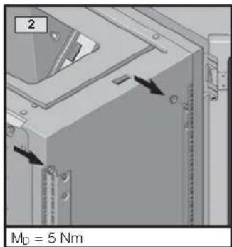
text_image
2 MD = 5 Nm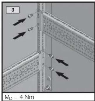
text_image
3 M_D = 4 Nm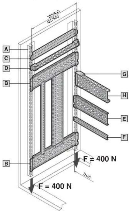
text_image
325/400 425/500 A C D B G H E F B F = 400 N B-25 F = 400 N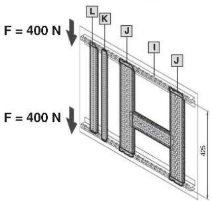
text_image
F = 400 N F = 400 N L K J I J 425| A | 5001.050 | |
| B | 8612.140 8612.150 | |
| C | 4694.000 4695.000 | |
| D | 4169.000 4170.000 | |
 | |||
| 600 800 1200 1600 | |||
| E | 8612.060 8612.080 8612.020 - | ||
| F | 8800.130 4579.000 -- | ||
| G | 8800.330 | ||
| H | 4376.000 4377.000 4378.000 4387.000 | ||
 | |||
| 600 800 1200 1600 | |||
| I | 5001.050 5001.051 5001.053 | 5001.054 | |
| J | 8612.150 | ||
| K | 4695.000 | ||
| L | 8612.250 | ||
TX25

text_image
Technical diagram of a cabinet with numbered components and dimension annotations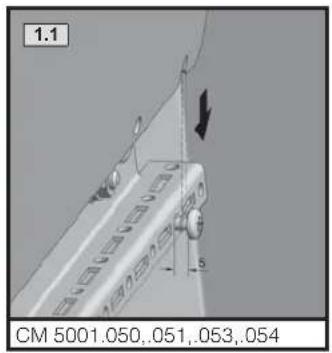
text_image
1.1 CM 5001.050,051,053,054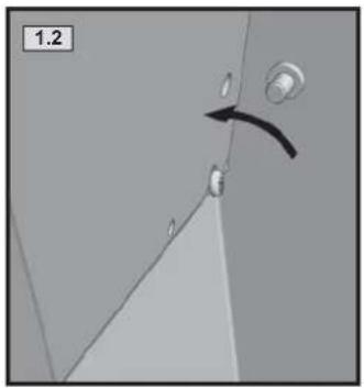
natural_image
3D diagram of a door corner with a black arrow indicating direction (no text or symbols)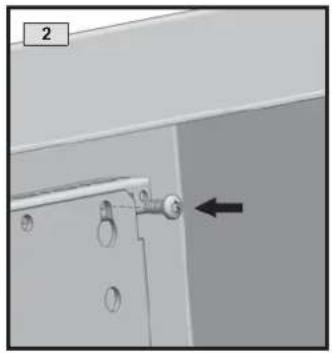
natural_image
Close-up of a mechanical component with a black arrow pointing to a detail (no text or symbols visible)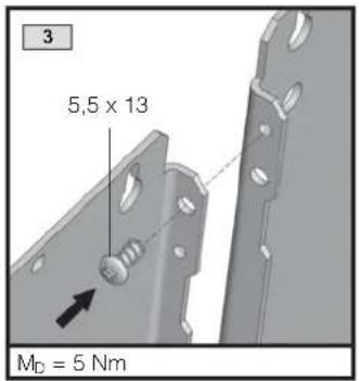
text_image
3 5,5 x 13 MD = 5 Nm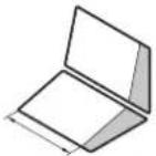 | Max. | F_max |
| 600 1 x TP 6730.330 700 N | ||
| 800 1 x TP 6730.340 700 N | ||
| 1200 | 2 x TP 6730.3101 x TP 6730.340 | 700 N |
| 1600 | 1 x TP 6730.3301 x TP 6730.340 | 700 N |
CM 5001.075
Bei dynamischer Belastung
During dynamic load

text_image
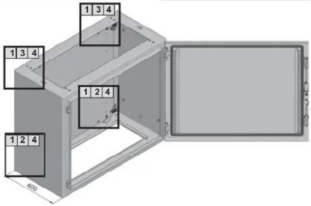
1 3 4 1 3 4 1 2 4 1 2 4 400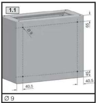
text_image
1.1 Ø9 65 45 40,5 40,5 Ø 9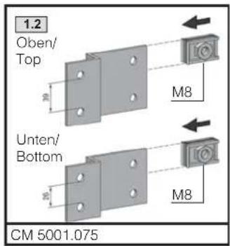
text_image
1.2 Oben/ Top M8 Unten/ Bottom M8 CM 5001.075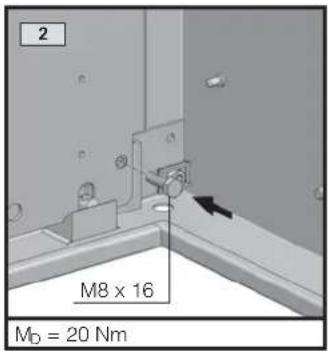
text_image
2 M8 x 16 MD = 20 Nm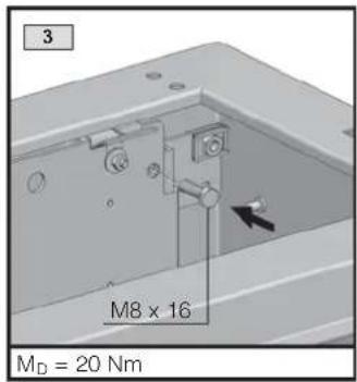
text_image
3 M8 x 16 MD = 20 Nm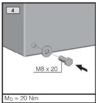
text_image
4 M8 x 20 MD = 20 Nm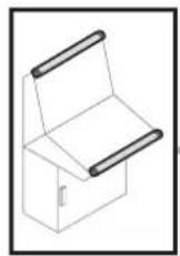
natural_image
3D diagram of a mechanical device with two views showing internal components and directional arrows (no text or symbols)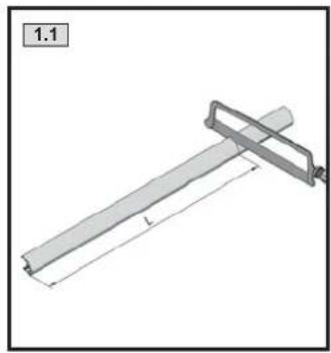
natural_image
Technical drawing of a mechanical lever or support structure with dimension lines (no text or symbols)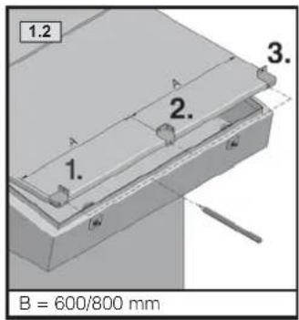
text_image
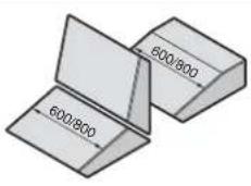
1.2 A 2. 3. 1. B = 600/800 mm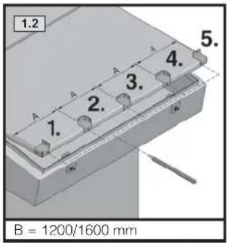
text_image
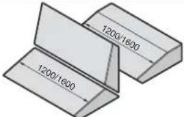
1.2 5. 1. 2. 3. 4. B = 1200/1600 mm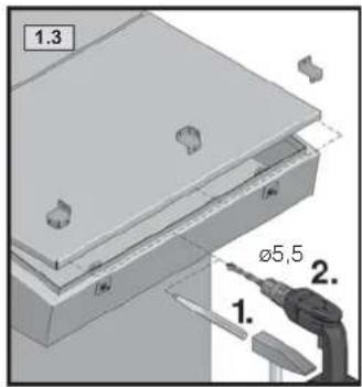
text_image
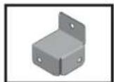
1.3 ø5,5 1. 2.| Best.-Nr. TP | ||
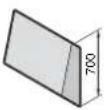
| 600 573 | 6731.120 | |
| 800 | 773 | |
| 1200 1173 | ||
| 1600 1573 |
natural_image
Technical illustration showing two views of a mechanical component with arrows indicating direction (no text or symbols present)
natural_image
Mechanical component diagram showing a cylindrical shaft with mounting flanges and directional arrows indicating motion (no text or symbols)
natural_image
Diagram of a mechanical or architectural component with an arrow indicating rotation (no text or symbols present)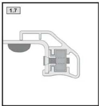
natural_image
Pure mechanical component diagram without any text, numbers, or symbols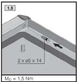
text_image
1.8 2 x Ø5 x 14 MD = 1,5 Nm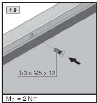
text_image
1.9 1/3 x M5 x 12 MD = 2 Nm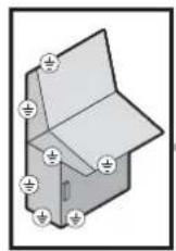
text_image
Technical diagram of a mechanical device with numbered components for identification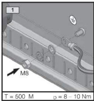
text_image
1 M8 T = 500 M D = 8 - 10 Nm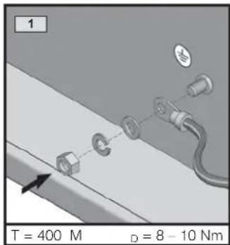
text_image
1 T = 400 M D = 8 - 10 Nm| 1 | 2 | 3 | ||
| M8 x 30 1 x | ||||
| M6 x 12 1 x | ||||
| ∅ 8,2 1 x | ||||
| ∅ 6,1 1 x | ||||
| M8 1 x 2 x | ||||
| M6 1 x | ||||
| A 8,4 1 x 1 x | ||||
| A 6,4 1 x | ||||
| A 8 1 x 1 x | ||||
| 1 x 1 x 1 x |
text_image
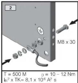
2 M8 x 30 T = 500 M D = 10 - 12 Nm th^2 x TK = 8,1 x 10^6 A^2 s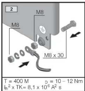
text_image
2 M8 M8 x 30 T = 400 M D = 10 - 12 Nm In² x TK = 8.1 x 10⁶ A² s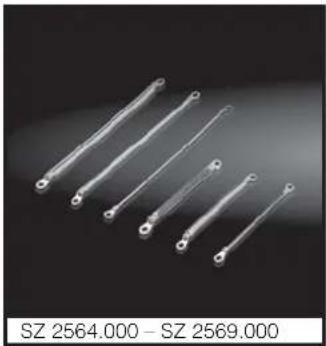
natural_image
Six metallic tool tips arranged diagonally on a dark background (no text or symbols visible)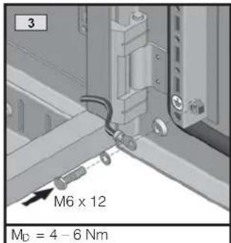
text_image
3 M6 x 12 MD = 4 - 6 Nm
natural_image
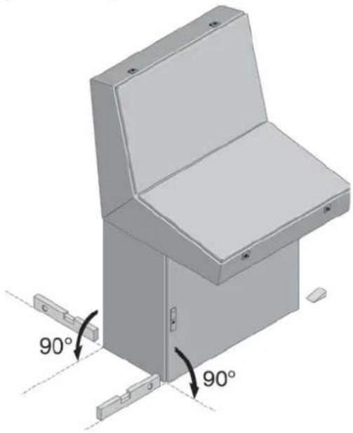
3D diagram of a mechanical cabinet with 90-degree angle annotations (no text or symbols on the diagram itself)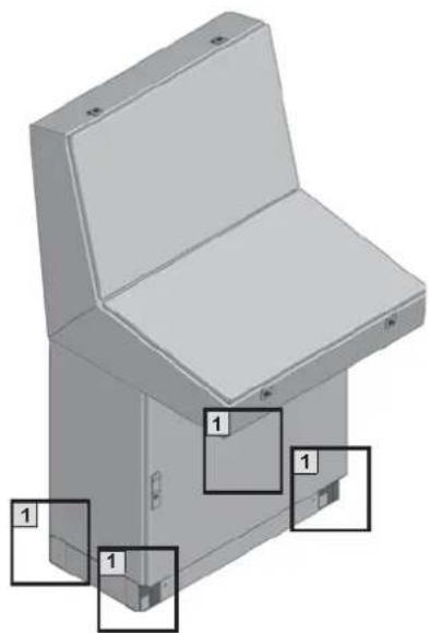
natural_image
3D diagram of a mechanical cabinet or enclosure with labeled parts (no text or symbols present)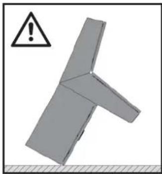
natural_image
3D mechanical component with warning symbol and crosshair (no text or labels)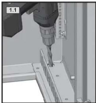
natural_image
3D mechanical assembly showing a drill bit interacting with a workpiece (no visible text or symbols)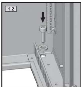
natural_image
Mechanical assembly diagram showing a bolt inserted into a housing with a downward arrow indicating motion (no text or symbols present)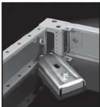
natural_image
Mechanical assembly showing a metal bracket with mounting holes and a mounted component (no visible text or symbols)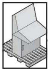


Q_s [W]
 |  |  |  |  | |||
 |  |  |  | ||||
| 600 120 95 90 115 110 100 115 | |||||||
| 800 155 115 110 140 135 115 130 | |||||||
| 1200 220 160 150 200 185 145 160 | |||||||
| 1600 280 205 190 250 235 175 190 | |||||||
Rittal – The System.
Faster – better – everywhere.
■Enclosures
■Power distribution
■Climate control
■IT infrastructure
■Software & services