
PCD25178N - Réfrigérateur Pelgrim - Notice d'utilisation et mode d'emploi gratuit
Retrouvez gratuitement la notice de l'appareil PCD25178N Pelgrim au format PDF.
| Type de produit | Réfrigérateur encastrable |
| Marque | Pelgrim |
| Modèle | PCD25178N |
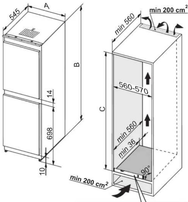
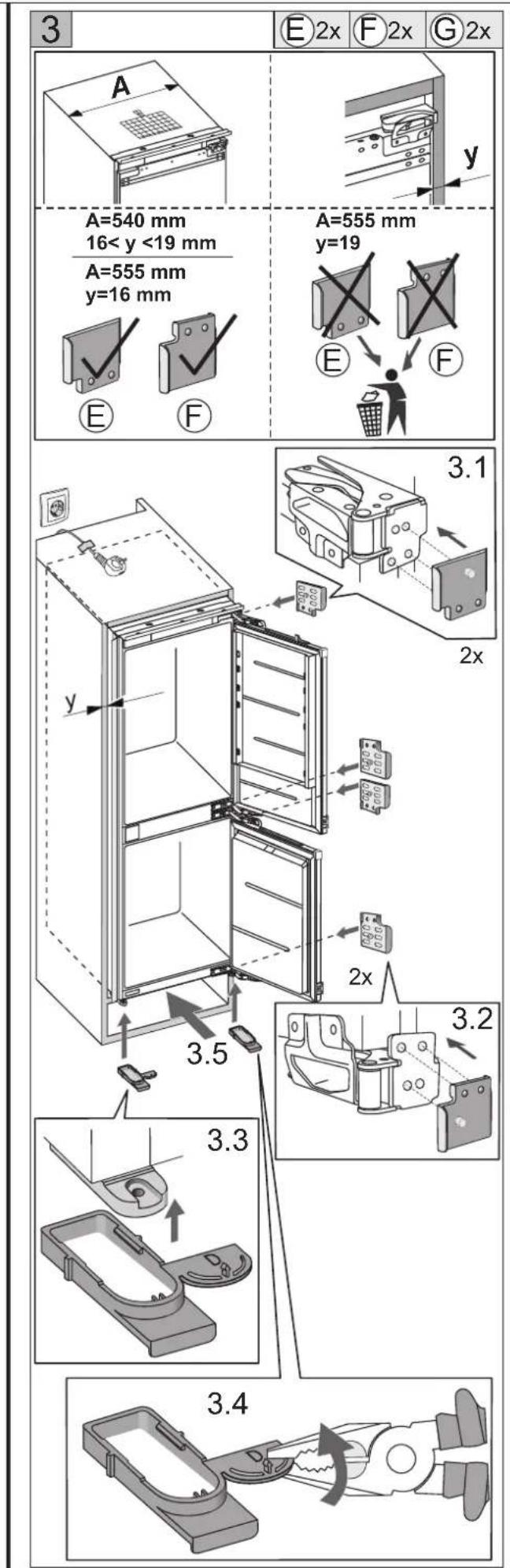
| Largeur | 540 mm |
| Hauteur | 1772 mm |
| Profondeur | 545 mm (approx.) |
| Dimensions de l'encastrement | H 1775-1780 mm |
| Volume total | 250 L (estimation) |
| Classe énergétique | E (estimation) |
| Alimentation électrique | 220-240 V, 50 Hz |
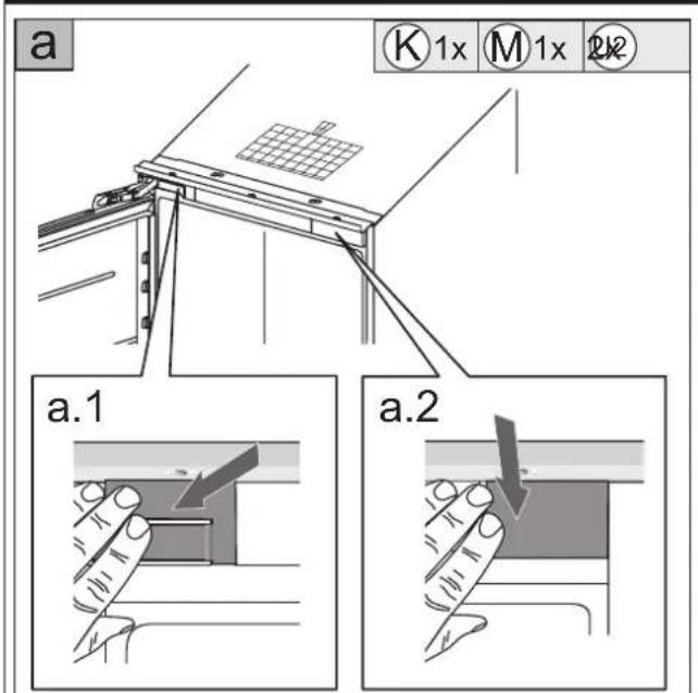
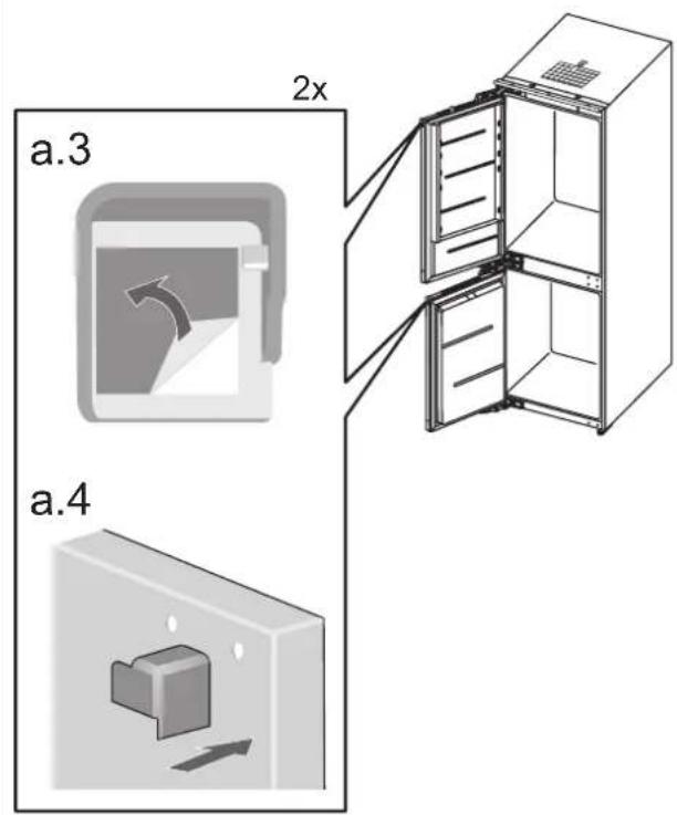
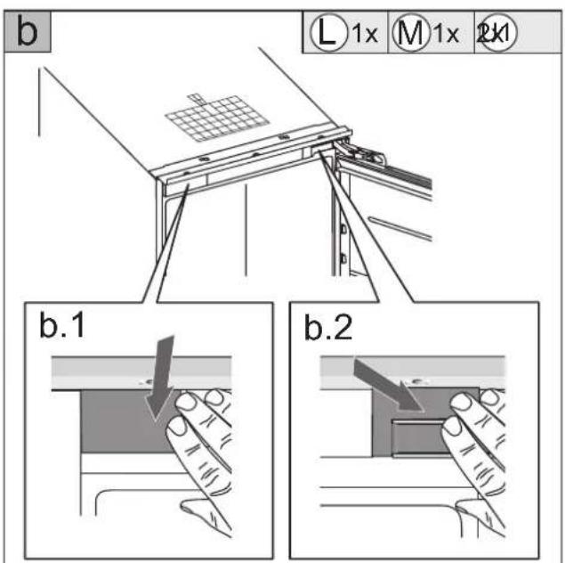
| Réversibilité de la porte | Oui |
| Aération nécessaire | Min. 200 cm² |
| Réfrigérant | R600a (estimation) |
| Niveau sonore | 42 dB (estimation) |
| Poids net | 50 kg (estimation) |
| Type d'éclairage | LED |
| Fonction vacances | Non |
| Capacité de congélation | 4 kg/24h (estimation) |
| Classe climatique | SN-ST |
FOIRE AUX QUESTIONS - PCD25178N Pelgrim
Questions des utilisateurs sur PCD25178N Pelgrim
0 question sur cet appareil. Repondez a celles que vous connaissez ou posez la votre.
Poser une nouvelle question sur cet appareil
Téléchargez la notice de votre Réfrigérateur au format PDF gratuitement ! Retrouvez votre notice PCD25178N - Pelgrim et reprennez votre appareil électronique en main. Sur cette page sont publiés tous les documents nécessaires à l'utilisation de votre appareil PCD25178N de la marque Pelgrim.
MODE D'EMPLOI PCD25178N Pelgrim
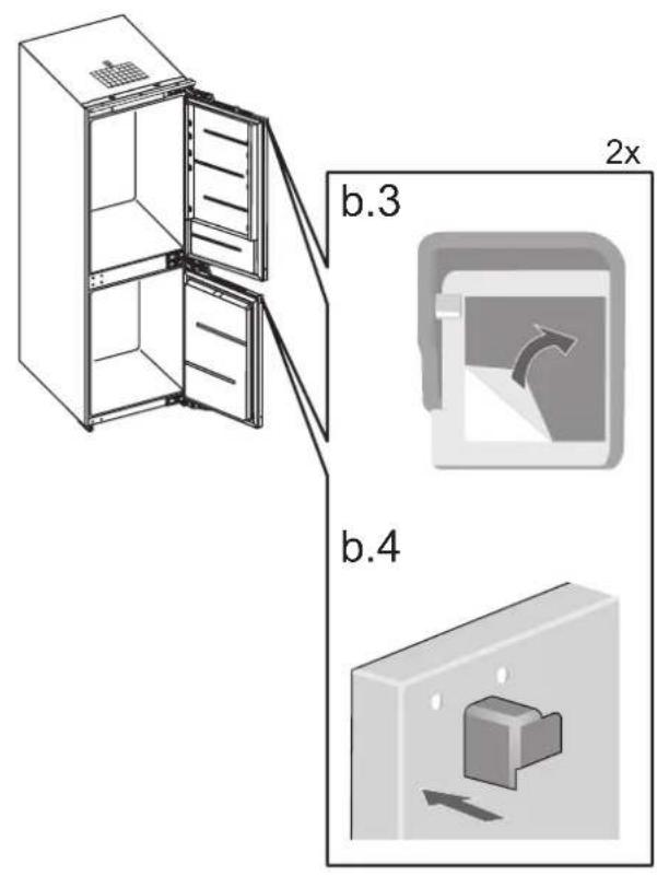
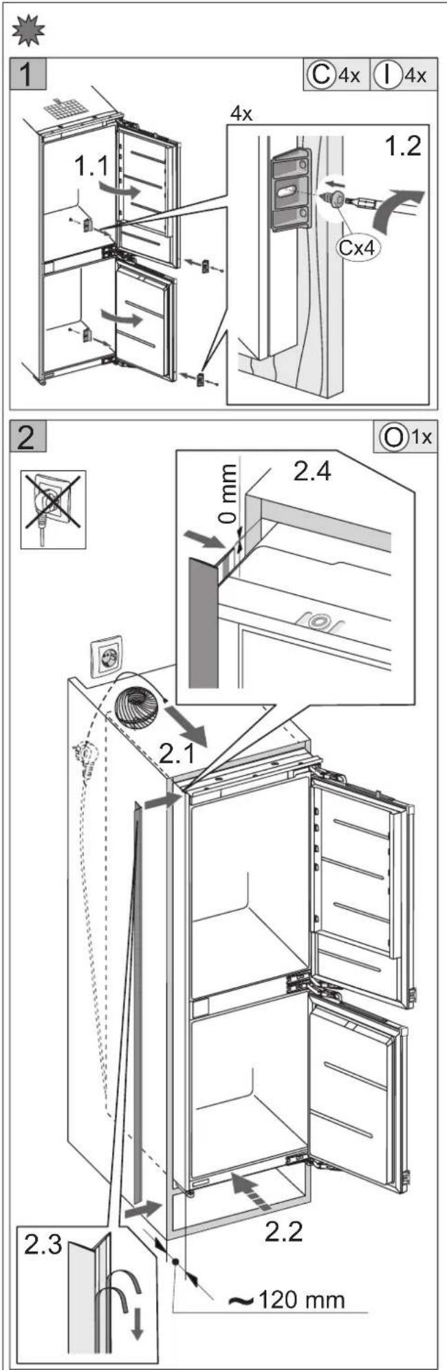
EN MOUNTING INSTRUCTIONS
DE EINBAUANWEISUNG
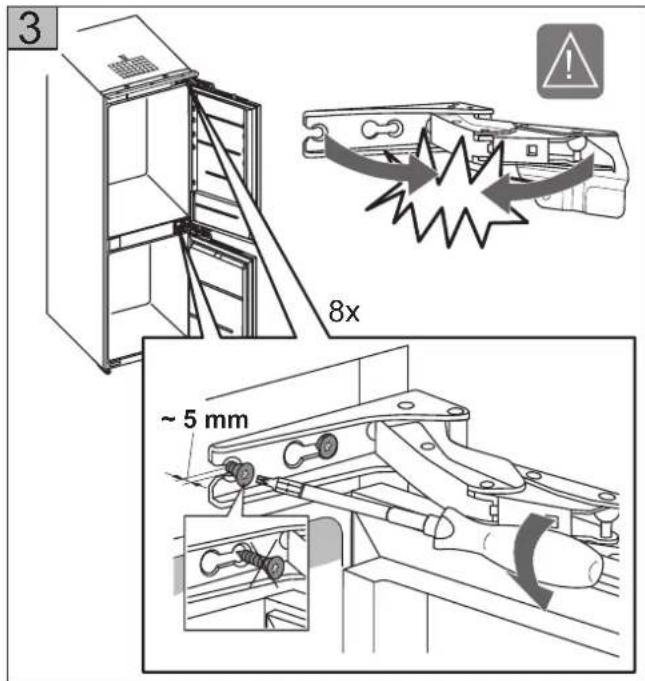
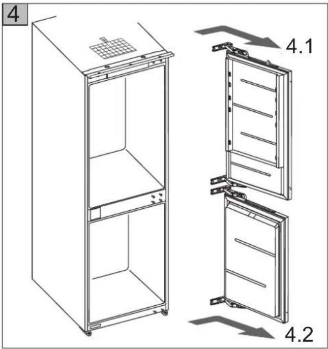
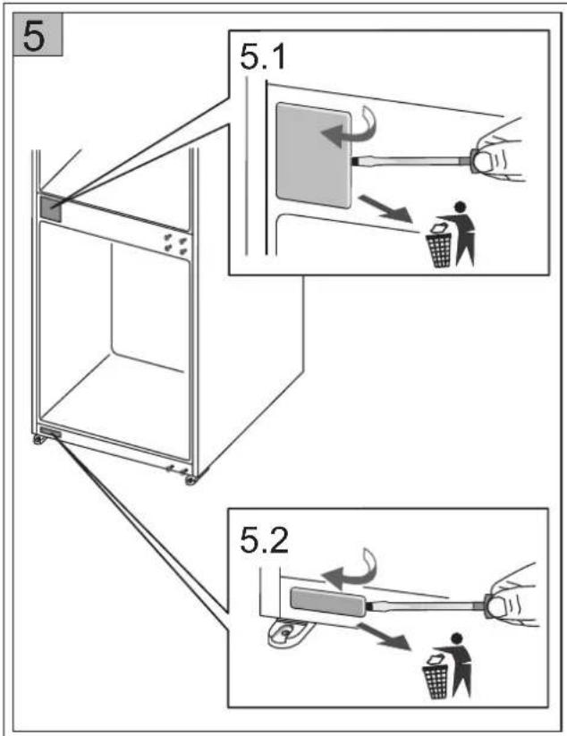
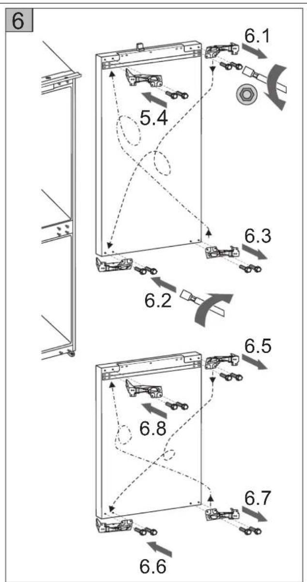
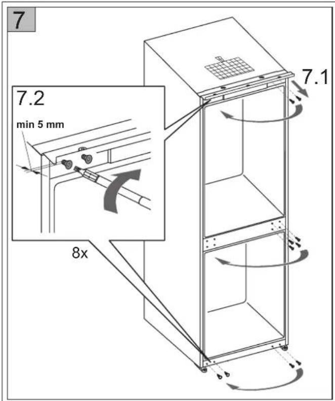
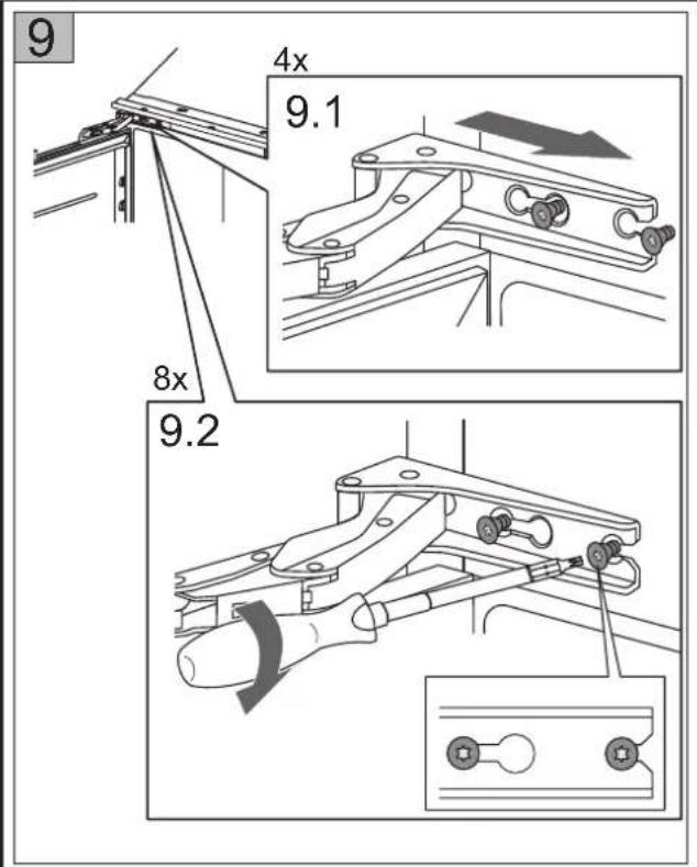
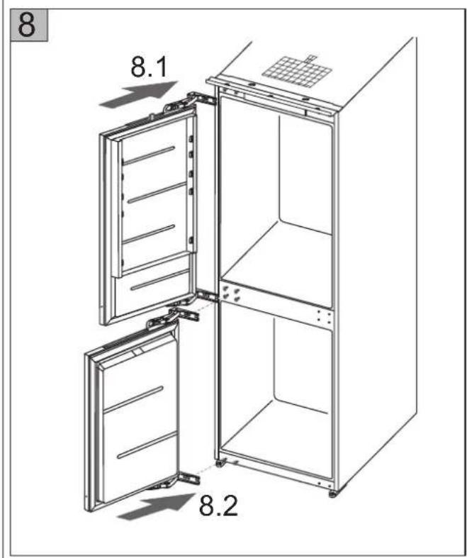
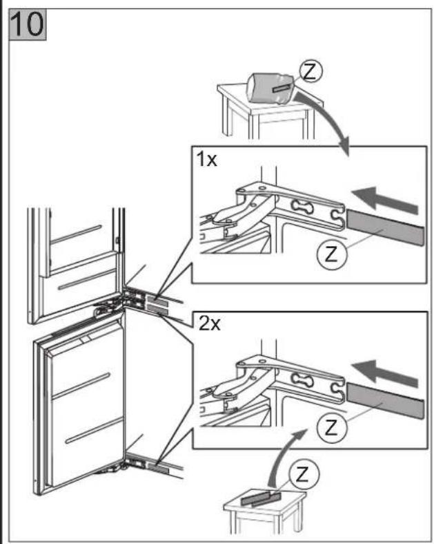
FR NOTICE D'INSTALLATION
NL INBOUW-HANDLEIDING
IT INSTRUZIONI PER L'INSTALLAZIONE
ES INSTRUCCIONES PARA EMPOTRAR
NO MONTERINGSANVISNING
DA MONTERERINGSANVISNING
SE MONTERINGSANVISNING
FI ASENNUSOHJE
SI NAVODILA ZA VGRADNJO
HR UPUTE ZA UGRADNJU
SR UPUTSTVA ZA UGRADNJU
RU РУКОВОДСТВО ПО МОНТАЖУ
KZ ОРНАТУ ЖОННДЕГІ НУСКАУЛЫК
ZH/CN 嵌入安装说明
ZH/TW 嵌入安裝說明

| A (mm) | B (mm) | C (mm) |
| 540 | 1772 | 1775-1780 |
| 555 | 1772 | 1775-1780 |
natural_image
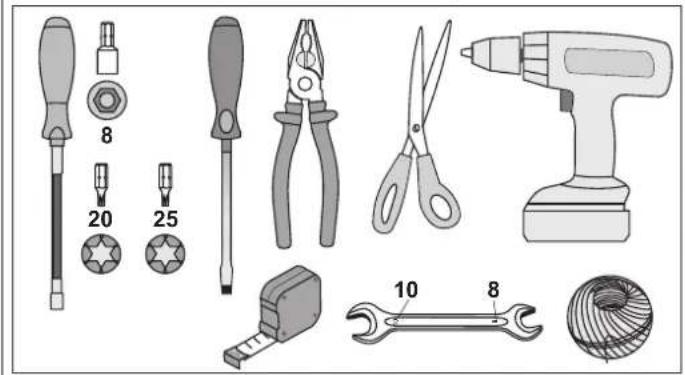
Illustration of various tools including screwdriver, pliers, power tool, and wire coil (no text or symbols present)
natural_image
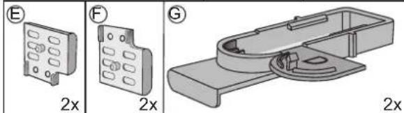
Technical illustration of a mechanical component with three views (E, F, G) showing internal structure and mounting base (no text or symbols)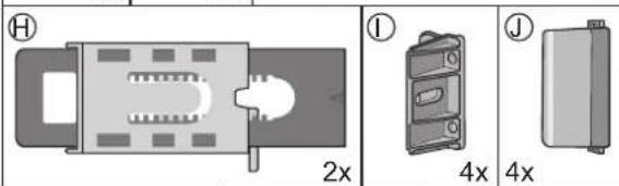
natural_image
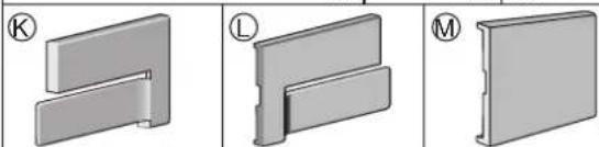
Three 3D mechanical part diagrams labeled K, L, and M, showing different structural configurations (no text or symbols beyond labels)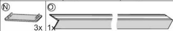
natural_image
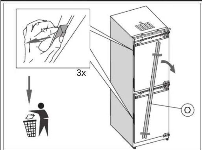
Two 3D rectangular objects with internal markings, one labeled with a circled number (N) and the other with an open circle (O), both scaled at 3x and 1x respectively (no text or symbols on the objects themselves)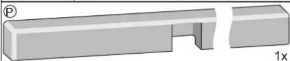
natural_image
3D diagram of a rectangular mechanical part with an open slot and a separate cut section, labeled '1x' (no text or symbols on the object itself)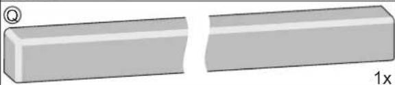
natural_image
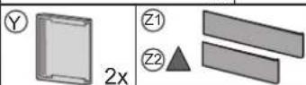
Two 3D rectangular blocks with a small circular symbol on top-left, one cut to form a wedge, the other flat (no text or symbols)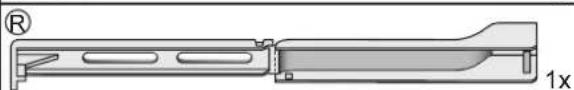
natural_image
Technical line drawing of a mechanical component with no visible text or symbols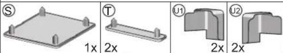
natural_image
Four 3D mechanical part diagrams labeled S, T, U1, U2 with dimension annotations (1x, 2x) — no readable text or symbols beyond labels.
flowchart
graph TD
    A["House 1"] -->|A| Question
    B["House 2"] -->|B| Question
    Question -->|A| Question1
    Question1 -->|B| Question2
    Question2 -->|A| Question3
    Question3 -->|B| Question4
    Question4 -->|A| Question5
    Question5 -->|B| Question6
    Question6 -->|A| Question7
    Question7 -->|B| Question8
    Question8 -->|A| Question9
    Question9 -->|B| Question10
    Question10 -->|A| Question11
    Question11 -->|B| Question12
    Question12 -->|A| Question13
    Question13 -->|B| Question14
    Question14 -->|A| Question15
    Question15 -->|B| Question16
    Question16 -->|A| Question17
    Question17 -->|B| Question18
    Question18 -->|A| Question19
    Question19 -->|B| Question20
    Question20 -->|A| Question21
    Question21 -->|B| Question22
    Question22 -->|A| Question23
    Question23 -->|B| Question24
    Question24 -->|A| Question25
    Question25 -->|B| Question26
    Question26 -->|A| Question27
    Question27 -->|B| Question28
    Question28 -->|A| Question29
    Question29 -->|B| Question30
    Question30 -->|A| Question31
    Question31 -->|B| Question32
    Question32 -->|A| Question33
    Question33 -->|B| Question34
    Question34 -->|A| Question35
    Question35 -->|B| Question36
    Question36 -->|A| Question37
    Question37 -->|B| Question38
    Question38 -->|A| Question39
    Question39 -->|B| Question40
    Question40 -->|A| Question41
    Question41 -->|B| Question42
    Question42 -->|A| Question43
    Question43 -->|B| Question44
    Question44 -->|A| Question45
    Question45 -->|B| Question46
    Question46 -->|A| Question47
    Question47 -->|B| Question48
    Question48 -->|A| Question49
    Question49 -->|B| Question50
A

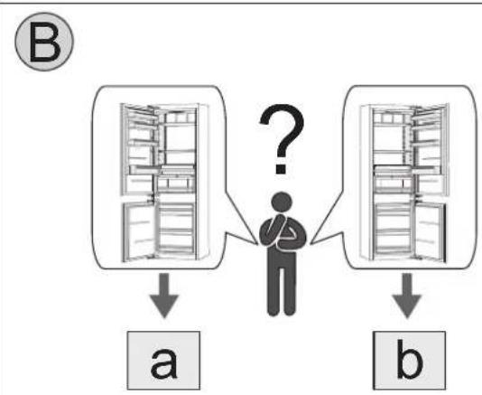
flowchart
graph TD
A["Person"] --> B["a"]
A --> C["b"]
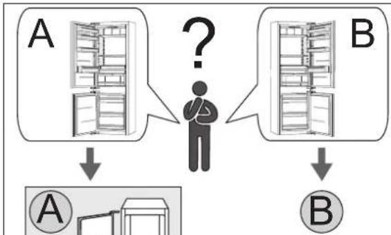
D["Question mark"] --> E["?"]
style D fill:#f9f,stroke:#333
natural_image
Mechanical assembly diagram showing a piston-cylinder joint interacting with a motor (no text or labels)flowchart
graph TD
    subgraph_D["Structure"]
        A1["a= b=c"] --> B1["a= b=c"]
        B1 --> C1["c"]
        C1 --> D1["a= b=c"]
    end
    subgraph_E1["Structure"]
        A2["a≠b≠c"] --> B2["a≠b≠c"]
        B2 --> C2["c"]
        C2 --> D2["a= b=c"]
    end
    subgraph_E2["Structure"]
        A3["a≠b≠c"] --> B3["a≠b≠c"]
        B3 --> C3["c"]
        C3 --> D3["a= b=c"]
    end
    style D fill:#f9f,stroke:#333
    style E1 fill:#ccf,stroke:#333
    style E2 fill:#ccf,stroke:#333
natural_image
Mechanical assembly diagram showing a lever mechanism with no visible text or symbolsnatural_image
Mechanical linkage diagram showing a lever mechanism with motion arrows (no text or symbols)natural_image
Technical line drawing of a mechanical bracket assembly (no text or symbols)natural_image
Technical line drawing of a mechanical bracket assembly (no text or symbols)natural_image
Mechanical assembly diagram showing a bracket with mounting holes and a curved arrow indicating motion (no text or symbols)natural_image
Technical diagram of a mechanical bracket assembly with mounting base (no text or symbols)flowchart
graph LR
    A["Person confused"] --> B["Truck in table with a question mark"]
    B --> C["Truck in trash bin with a checkmark"]

Marque : Pelgrim
Modèle : PCD25178N
Catégorie : Réfrigérateur