FLEX 235 - Caméscope ARRI - Notice d'utilisation et mode d'emploi gratuit
Retrouvez gratuitement la notice de l'appareil FLEX 235 ARRI au format PDF.

| Type de produit | Caméscope cinéma 35mm (MOS) |
| Marque | ARRI |
| Modèle | FLEX 235 |
| Alimentation | 20-35 V DC, prise 2 broches Fischer |
| Température de fonctionnement | -20 °C à +50 °C |
| Humidité de fonctionnement | 5 % à 95 % sans condensation |
| Altitude maximale | 3000 m |
| Vitesses de prise de vue | 1 à 60 images/s (selon magazine, marche arrière possible) |
| Précision de vitesse | +/- 100 ppm sur -20 °C à +50 °C |
| Connectique | Prise d'alimentation 2 broches, 2 prises R/S, prise accessoire 11 broches |
| Accessoires compatibles | UMC-1, UMC-3, RCU-1, WRC-1, ESU-1, IVS-235 |
| Magazines compatibles | Arrimag 120, 120S, ARRI III 150m, 60m (pas les magazines 300m) |
| Fonctions spéciales | Conversion 3/4 perforations, mise à jour logicielle par PC, obturateur miroir |
| Entretien recommandé | Nettoyage des surfaces de contact, vérification de la distance focale de bride |
| Sécurité | Débrancher l'alimentation avant intervention, porter des lunettes de protection |
| Pièces détachées disponibles | Courroies crantées (K5.49859.0, K5.65292.0, K5.65293.0), kit conversion 3 perforations (K2.55018.0) |
FOIRE AUX QUESTIONS - FLEX 235 ARRI
Questions des utilisateurs sur FLEX 235 ARRI
0 question sur cet appareil. Repondez a celles que vous connaissez ou posez la votre.
Poser une nouvelle question sur cet appareil
Téléchargez la notice de votre Caméscope au format PDF gratuitement ! Retrouvez votre notice FLEX 235 - ARRI et reprennez votre appareil électronique en main. Sur cette page sont publiés tous les documents nécessaires à l'utilisation de votre appareil FLEX 235 de la marque ARRI.
MODE D'EMPLOI FLEX 235 ARRI
7/23/2007

Arriflex 235
Service Manual
Prepared for:
Bill Bennett, ASC
Content:
1. Mechanical:
Checking the Flange Focal Distance 3
235 Spacer Plate. 4
3 Perforation Conversion. 5
Adjust Timing. 8
Changing drive belts. 9
2. Electronically:
Scope. 10
Safety advice and conventions. 10
Specifications 11
Connector pin outs. 12
3. Software update:
Software Update Procedure. 13
4. Tools:
Tool list. 15
1. Mechanical:
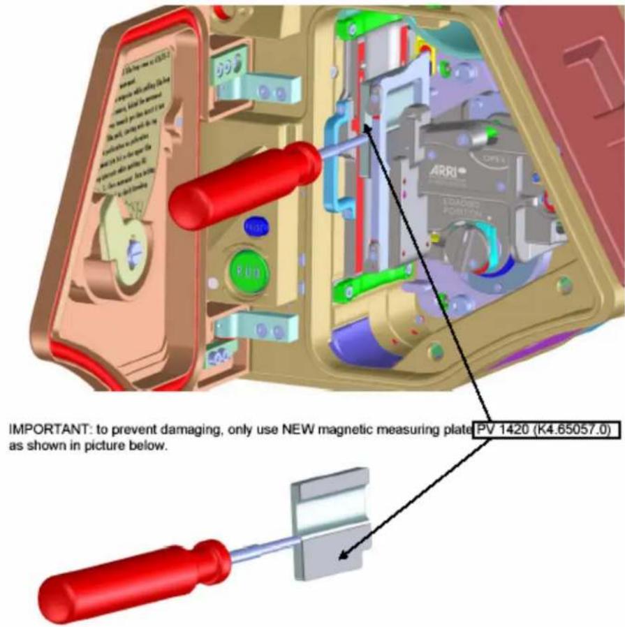
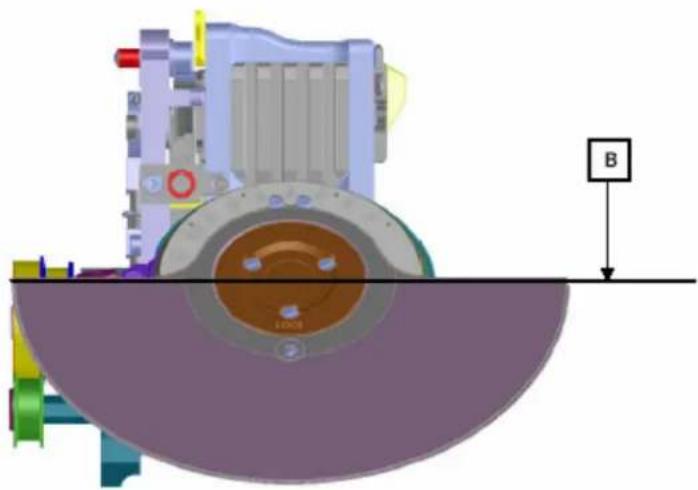
Checking the Flange Focal Distance 51,98 -0,01 mm
Measuring and adjusting is done similar to the 435.
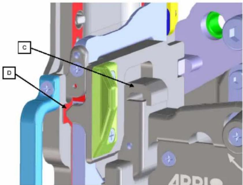
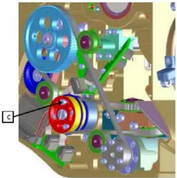
Notes regarding the new ARRIFLEX 235 spacer plate
The film gap between film gate and spacer plate is NOT adjustable!
The nominal film gap of 0.175 mm ± 0.005 mm is guaranteed by manufacturing of the spacer plate. 3 faces (A) are raised 0.175 mm in relation to the 5 ribs (B), which form the back side of the film gap.
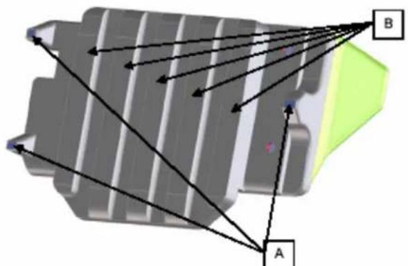
A spring loaded lever (C) presses the 3 faces on the film plane (D) of the film gate. By this means the dimension and parallelism of the film gap is guaranteed. Of course, the mating surfaces must be always kept clean!
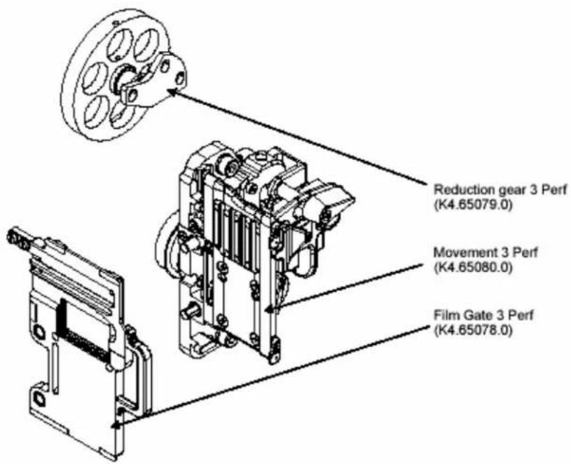
3 Perf Conversion
The ARRIFLEX 235 3 Perf Conversion Kit (K2.55018.0, in preparation) includes:
Notes
- 3 Perf ground glasses are not included in the 3 Perf Conversion Kit. They have to be ordered separately.
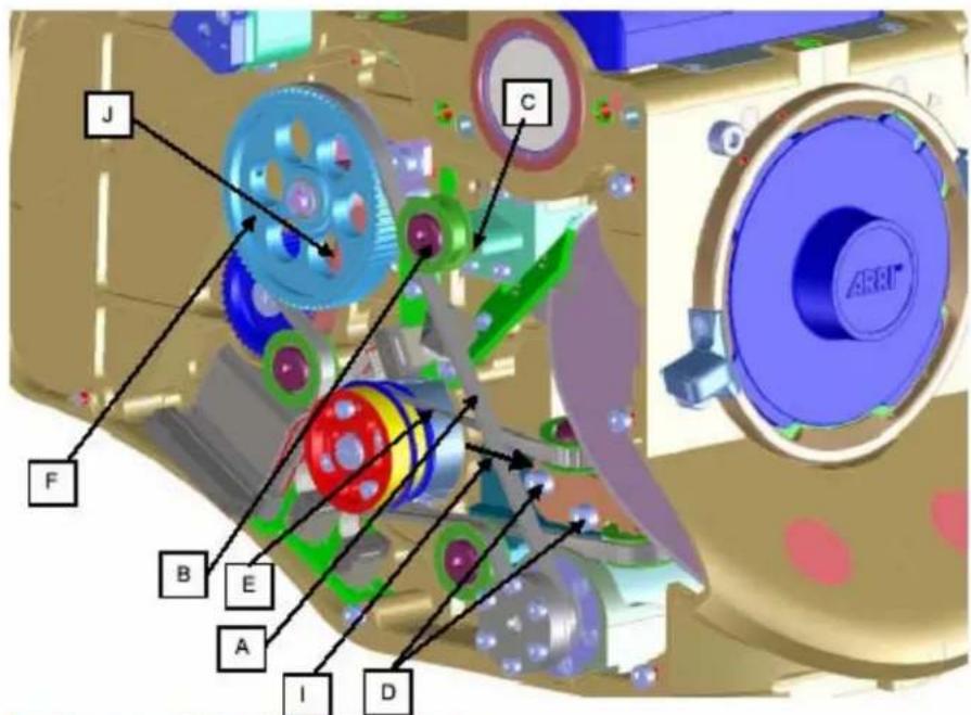
Procedure
- Open movement and take out the 4 Perf film gate.
- Before opening the electronic cover turn the mirror shutter out of the lens-port area toward camera left.
- Open electronic cover (7 screws), take care of connection between electronic cover and body, disconnect electronic cover.
- Remove long drive belt (A)
- Remove upper deflection roller (B) and and mount it in thread (C).
- Untighten screws (D) of roller block.
- Remove shutter drive belt (E) from movement pulley.
- Remove 4 Perf reduction gear (F).
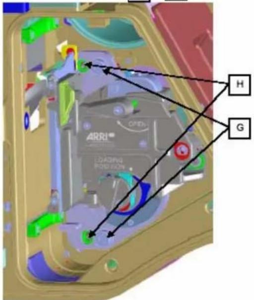
- Remove movement (2 screws (G)) by gently pulling it off from 2 locating pins (H).
- Install 3 Perf movement
- Install 3 Perf reduction gear
- Install shutter drive belt on movement pulley.
- Install long drive belt.
- Adjust belt tensions
apply force of 5 N (l) on roller block to tense shutter drive belt.
Tense long drive belt in such a way, that with a test load of 4 N, belt gives way 5-6mm from tangential situation.
- Tense short drive belt (J) in such a way, that with a test load of 4 N, belt gives way 1-1.5 mm from tangential situation.
- Install 3 Perf film gate.
- Check flange focal distance and parallelism of film gate to PL-mount.
- Adjust timing as described in "Adjust timing".
- Switch electronics to 3 Perf mode:
Activation of the Service Mode
Power-on the camera.
Choose "display mode 4" by pressing the MODE button 3 times.
Keep the SET button pressed and briefly press the SEL button 3 times.
The display changes to Service Mode and the following display appears as long as SET is pressed:
E 25° d 31°
In the 235 Service Mode exist 5 display modes altogether which can be activated in sequence by the MODE button.
In the individual modes, the usual run functions are available. Only differing test data is displayed.
Attention: Emergency switch-off and protective functions may be deactivated occasionally.
Press the MODE button repeatedly until Service display mode 2 will be displayed
Upper line: 3 or 4 perforation
4PERF 0000
To change from 3 to 4 perforation or vice versa keep the SET button pressed down and briefly press the SEL button 4 times. The value toggles between 3 and 4.
Attention: only change this value, if you really want to change the movement type!
Deactivation:
To exit from Service Mode, choose "display mode 4" again, hold the SET button pressed and briefly press SEL button one time or switch-off the camera.
19.Shoot test film.
7/23/2007
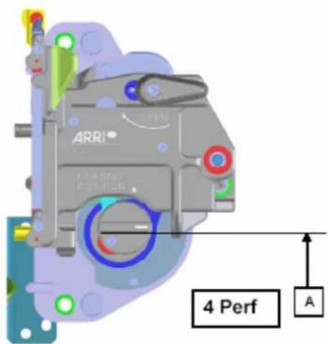
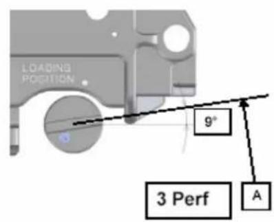
Adjust timing
- Untighten 4 screws (C).
- Position inching knob in position (A). In this position the registration pin penetrates the film at it's maximum.
- Position the mirror shutter in horizontal position (B).
- While keeping Position A and B, tighten 4 screws (C).
- Thread a piece of film and mark frame with a felt pen.
- Check timing, correct timing if required.
7.Shoot a test film.
7/23/2007
Changing drive belts
Required spare parts.
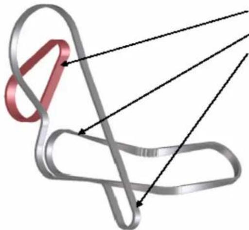
TOOTHED BELT 120 (K5.49859.0)
TOOTHED BELT S2M290-4B (K5.65292.0)
TOOTHED BELT S2M320-4B (K5.65293.0)
2. Electronically:
Scope
The 235 is a small, inexpensive MOS camera which is designed as a single motor cameras with timing belt drive for shutter and movement
The Main electronics of the ARRIFLEX 235 has the following interfaces and functionalities:
- Interface to the UMC-1 and UMC-3, ESU, RCU in a single mixed layout socket. The socket is designed in a way that the standard cables for the CCU-socket of the older cameras are compatible to it and it has three additional contacts for the ESU and ICU in the mid of the standard 8-pins of the CCU socket. This was done due to space restrictions.
Two separated R/S sockets - Optional accessory socket (for interfacing of a capping shutter and other future expansions)
Control and power stage for the camera motor
Display and user interface
The electronics is compatible to the following standard accessories
UMC-1 and UMC-3
RCU-1
WRC-1
ESU-1
IVS-235
The following accessories are not compatible and must not be used on the ARRIFLEX 235
RU
- CCU
Safety advice and conventions
The service must be carried out in a static free environment to prevent any damage to the sensitive electronics.
Disconnect the power cable before assembling, disassembling or any other work on the camera.
When it can not be avoided to run an opened camera always take care that no obstacles are in the way of moving parts.
Always wear safety glasses when running an open camera.
Do not handhold any part or touch a part of the camera while it is running.
Do not reach into the lens port.
Signals beginning with a n^* are low active signals.
Always refer to the current schematics and part lists for the latest version of the electronics.
Specifications
The electronics was designed to operate within the following limitations
Operating temperature: -20°C / +50°C
Humidity: 5% - 95% noncondensing
Altitude: 0 to 3000m
Camera speed
| Magazine | Fps min | Fps max | Reverse operation |
| Arrimag 120 | 1 | 60 | Yes |
| Arrimag 120S | 1 | 60 | Yes |
| Arrimag 300E | - | - | - |
| ARRI III 300m | - | - | - |
| ARRI III 150m | 1 | 60 | Yes |
| ARRI III 60m | 1 | 60 | No |
300m magazines must not be used with the ARRIFLEX 235.
Operating voltage: No
Nominal
20-35 volts dc
Turn on
Vbat>18.4 volts (+1/-0 volts)
Undervoltage switch off
V_bad < 18 volts (+1 / -0 volts)
Not ready below
V_sat < 21 volts (+0.5 / - 0 volts)
Overvoltage
Vbat>37 volts (+/-1 volt)
ESU operation: 3-60fps specified
Phase jitter
less than 4% @ 24fps
as static camera (camera not moved, panned...)
Accessory IF:
Control Interface for ICS
Camera Status
CAN Bus 120 Ohms terminated
Two motor control lines (step & direction)
Signal description: see connector description.
Speed accuracy:
fps: +/-100ppm @-20to +50°C, static camera,
measurement interval ≥ 10s
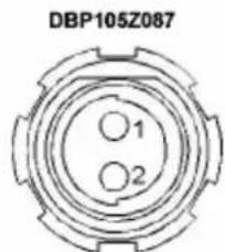
Connector pinouts
| Power supply socket 2pin Fischer E-Cover (W.W.Fischer DBP105Z087-130) | |||
| Pin | Signal | Level / Impedance | Description |
| 1 | GND | Power supply GND | |
| 2 | +24V | Power supply +24 volts | |
| R/S sockets E-Cover (W.W. Fischer DBP102A052-130) | |||
| Pin | Signal | Level / Impedance | Description |
| 1 | GND-AUX | Power supply GND | |
| 2 | 24V-AUX | Power supply +24 volts nom. (electronically fused, not stabilized) | |
| 3 | R/S | I/O | Multilevel R/S Signal according to ARRI specifications |
| Accessory socket 11pin E-Cover (W.W Fischer DBP104A114-130) The pinout is different to the W.W. Fischer factory drawings to maintain continuity with the standard 8-pin Fischer CCU socket | |||
| Pin | Signal | Level / Impedance | Description |
| 1 (W.W. Fischer pin 4) | CCU-TXD | RS232 | Serial interface to the RCU/CCU |
| 2 (W.W. Fischer pin 5) | CCU-RXD | RS232 | Serial interface to the RCU/CCU |
| 3 (W.W. Fischer pin 6) | 24V-AUX | Power supply +24 volts nom. (electronically fused, not stabilized) | |
| 4 (W.W. Fischer pin 7) | GND-AUX | Power supply GND | |
| 5 (W.W. Fischer pin 8) | n.c. | Currently not used / do not connect | |
| 6 (W.W. Fischer pin 9) | S-SECTOR | TTL Out | Shutter signal (was the I/O signal on the standard CCU socket which has never been used) |
| 7 (W.W. Fischer pin 10) | GND-AUX | Power supply GND | |
| 8 (W.W. Fischer pin 11) | PIL | TTL In | Pilot input from the ESU (was the LTC-IN signal on the standard CCU Socket) |
| 9 (W.W. Fischer pin 1) | R/S | Multilevel | Multilevel run/stop signal according to ARRI standard |
| 10 (W.W. Fischer pin 2) | ESU-SEL | TTL-IN | ESU detection signal |
| 11 (W.W. Fischer pin 3) | FIST-200 | TTL-OUT | 200Hz / fps Signal f-list (e.g. for the ICU) |

DBP102A052
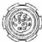
DBP104A114 (ARRI pinning: CCU +3pins)
All views from plug-in-side
3. Software update:
ARRIFLEX 235 SOFTWARE UPDATE PROCEDURE
Software update for the ARRIFLEX 235 can be done via PC - serial port.
The connection between camera and PC can be made via the following cables
K2.55011.0 KC 88-S or the
WLCC cable used for LCC connection
CAUTION: NEVER use CCU-cables KC-24 or KC-30 as they may damage your computer due to an additional power supply connection!
The update software as well as the latest software versions will be available via Internet via
http://www.arri.de/entry/update.htm
The packet consists of
235_Uploader.exe PC execution file
235.ini Control file for 235-upsloader.exe
CMC_F01xx.s19 firmware update file for CMC (Camera Main Controller)
CMC_FL01xx.mhx flashloader update file for CMC
CMC_S01xx.mhx main processor software update file for CMC main processor
IVS_S00xx.s19 software update file for IVS (Integrated Video System)
PIC_S01xx.s19 PIC software update file for CMC (Camera Main Controller)
xx stands for the current version
Load the update software to your PC.
Connect the update cable both on your PC 9-pin serial connector and the camera accessory connector.
Power-on your camera
Start the 235_Uploader.exe on your PC.
The following screen will appear:
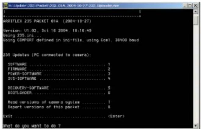
Function description:
1 SOFTWARE
loads another camera software version
2 FIRMWARE
loads another camera firmware version
3 POWER-SOFTWARE
loads another PIC-software version (responsible for power on/off behavior)
4 IVS-SOFTWARE
loads another IVS software version
5 RECOVERY-SOFTWARE
enables recovery from corrupted software, e.g. caused by power-fail during camera update
6 BOOTLoader
loads another camera bootloader software version
7.8
reports software / firmware versions on the screen as per description
Select the requested function by pressing the appropriate keyboard button.
The execution program starts the flashloader prior to the selected function to enable
communication between camera and the PC. This will last a few seconds.
The software inside the camera will be compared to the update version and displayed on the screen. You may then decide to really update the camera (or subsystem) or not.
After the selected function has been executed, the main screen will appear again and let you select another function or exit the program by pressing the "ENTER" button on your keyboard.
Note: If the POWER-SOFTWARE update has been selected, the camera will switch off automatically after update and must be re-powered by pressing the on/off button on the camera.
Switch off your camera. With the next power-on the loaded software will be executed.
4. Tools:
| Ident No. | Description Name | Price Notes | |||
| K4.65057.0 | Measuring plate | FFD | PV1420 | 926.00 | |
| K4.65058.0 | Film transport and channel PV1 | 421 3443.60 | |||
| K4.65056.0 | Film gate side rails PV1422 160 | 4.40 | |||
| K4.65144.0 | Sapphire on side rails PV1429 12 | 14.00 | |||
| 200635 | SW update cable n/a | 240.00 | Recommended | ||
Recomme
Note: Prices are subject to change without notice.