
KSU 250 Mobile - Support d'outil électrique METABO - Notice d'utilisation et mode d'emploi gratuit
Retrouvez gratuitement la notice de l'appareil KSU 250 Mobile METABO au format PDF.

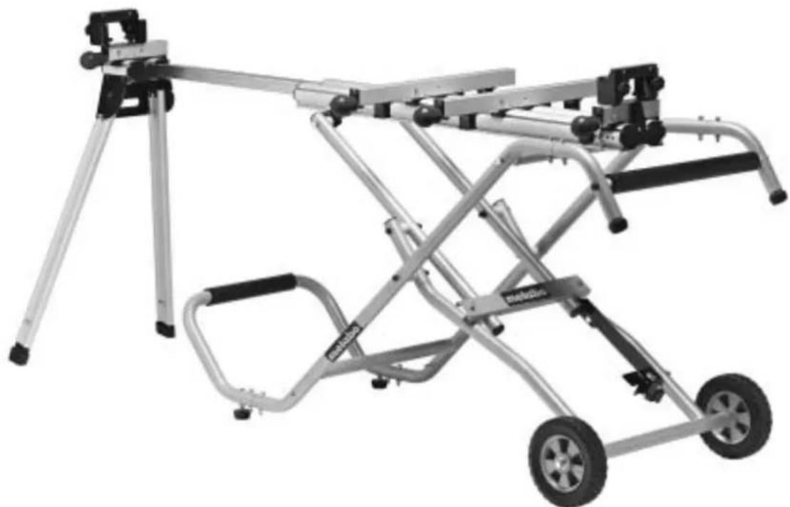
| Type de produit | Support d'outil électrique (poste de travail mobile) |
| Marque | Metabo |
| Modèle | KSU 250 Mobile |
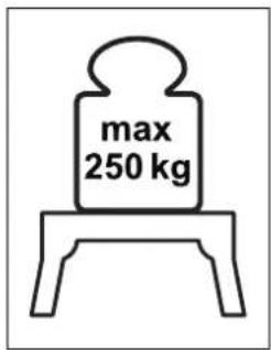
| Capacité de charge maximale | 250 kg |
| Matière principale | Acier robuste |
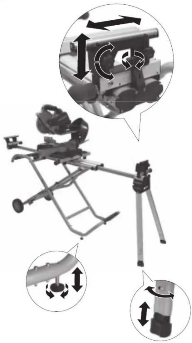
| Hauteur de travail | Réglable en continu |
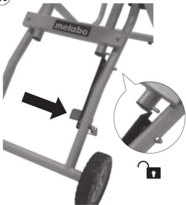
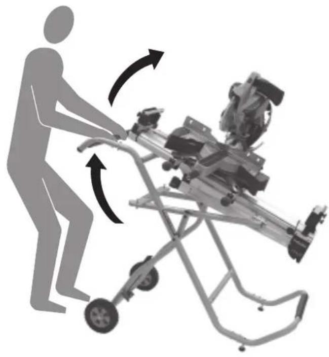
| Roulettes | 2 roues pivotantes, 2 roues fixes avec freins |
| Dimensions (L x l x H) | Environ 1000 x 600 x 800 mm |
| Poids net | Environ 35 kg |
| Plage de réglage en hauteur | De 700 mm à 1000 mm |
| Compatibilité | Scies, ponceuses, défonceuses, etc. |
| Fonctions principales | Support stable, mobilité, réglage en hauteur, blocage de sécurité |
| Entretien et nettoyage | Nettoyer avec un chiffon humide, lubrifier les parties mobiles, vérifier les freins |
| Sécurité | Freins sur roues, verrouillage de hauteur, pieds antidérapants |
| Pièces détachées et réparabilité | Disponibles auprès du SAV Metabo (roues, vis, patins) |
| Garantie | 3 ans (selon conditions Metabo) |
FOIRE AUX QUESTIONS - KSU 250 Mobile METABO
Questions des utilisateurs sur KSU 250 Mobile METABO
0 question sur cet appareil. Repondez a celles que vous connaissez ou posez la votre.
Poser une nouvelle question sur cet appareil
Téléchargez la notice de votre Support d'outil électrique au format PDF gratuitement ! Retrouvez votre notice KSU 250 Mobile - METABO et reprennez votre appareil électronique en main. Sur cette page sont publiés tous les documents nécessaires à l'utilisation de votre appareil KSU 250 Mobile de la marque METABO.
MODE D'EMPLOI KSU 250 Mobile METABO
metabo®
natural_image
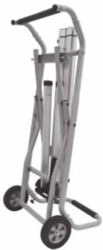
Mechanical support system with metal frame and wheels, no visible text or symbolsKSU 250 Mobile

D Maschinenständer
ENG Workstand
F Montants de la machine
NL Machinestandaard
IT Supporto della macchina
ES Base de la máquina
PT Suporte de máquina
DA Standeren
NO Maskinunderstell
SV Maskinstativ
FIN Jalusta
HU Gépállvány
POL Stojak pod urządzenie
EL Ορθοστάτης μηχανήματος
1


2
natural_image
3D rendering of a mechanical lifting frame with metal rods and support brackets (no text or symbols)3
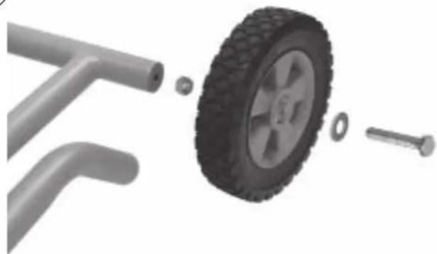
natural_image
3D illustration of a car wheel with attached parts, showing components like a tire, bolts, and a pipe (no text or symbols)4
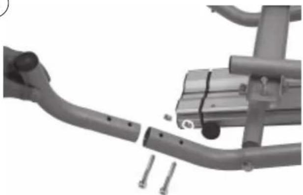
natural_image
Mechanical assembly showing a curved pipe with bolts and a mounted bracket (no visible text or symbols)5
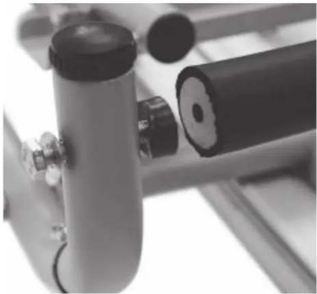
natural_image
Close-up of industrial equipment components including cylindrical tanks and a coiled cable, with no visible text or symbols.6
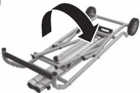
natural_image
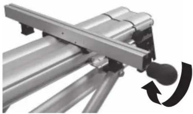
Mechanical vehicle chassis with wheels and a black arrow indicating rotation (no text or symbols)7
natural_image
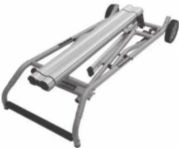
Metal mechanical device with wheels and frame structure (no visible text or symbols)8
natural_image
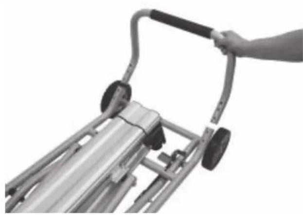
Close-up of a hand gripping a metal ramp lift (no text or symbols visible)9
natural_image
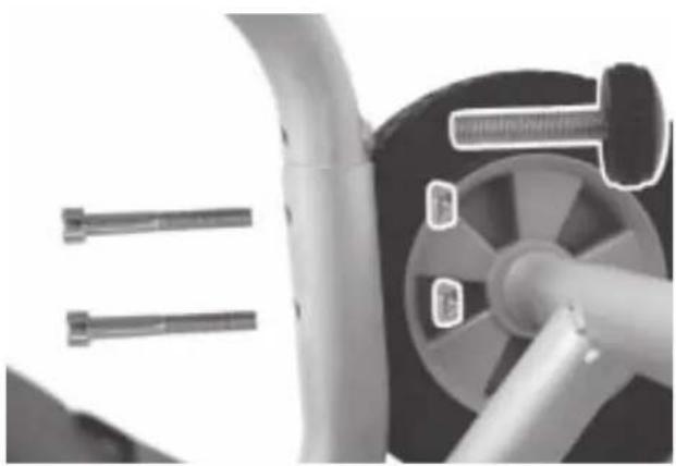
Close-up of a mechanical component with cylindrical parts and a central hub, no visible text or symbols10
natural_image
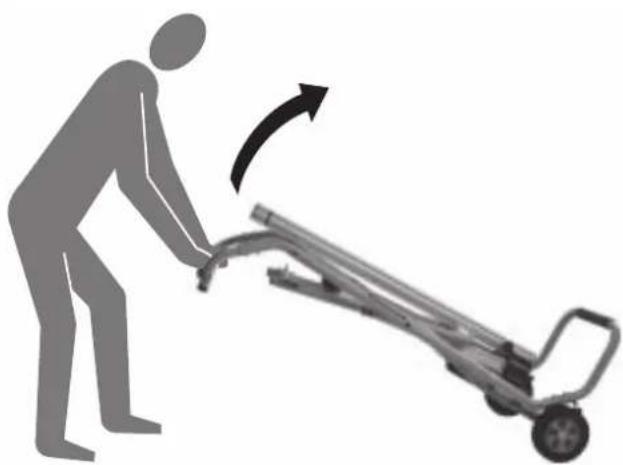
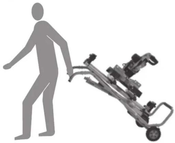
Silhouette of a person pushing a cart with an arrow indicating motion (no text or symbols)11
natural_image
Exterior view of a metal modular cart with wheels and handle (no text or symbols visible)12
natural_image
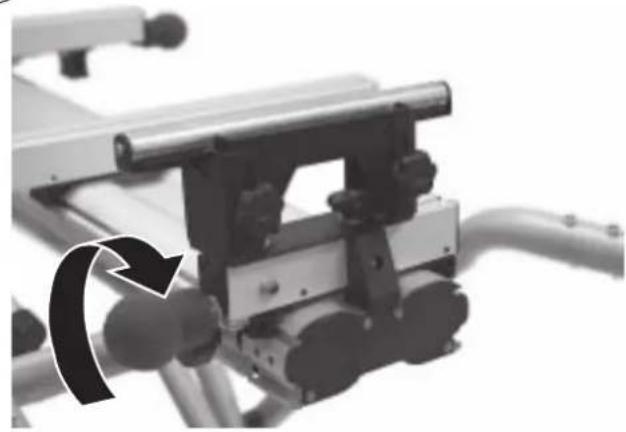
Close-up of a bicycle support structure with a close-up inset showing the mechanism (no text or symbols visible)13
natural_image
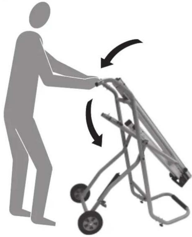
Silhouette of a person pushing a cart with directional arrows indicating motion (no text or symbols)14
natural_image
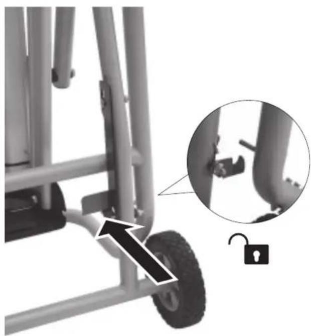
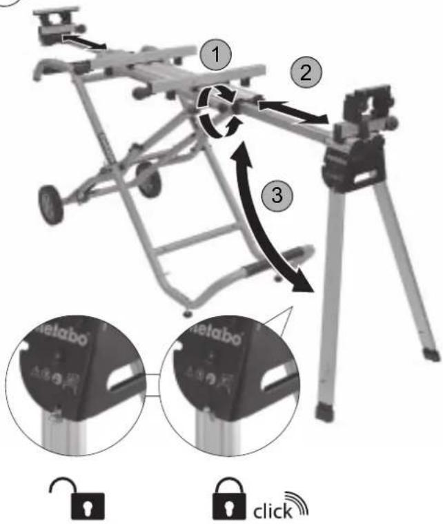
Mechanical device with attached frame and wheels, showing a close-up of a padlock mechanism (no text or symbols visible)15
natural_image
Mechanical assembly diagram showing a lever mechanism with a curved arrow indicating rotational motion (no text or symbols present)16
natural_image
Mechanical assembly with rotating components and a curved arrow indicating rotation (no text or symbols)17
18
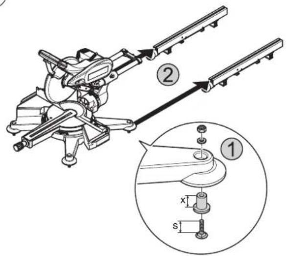
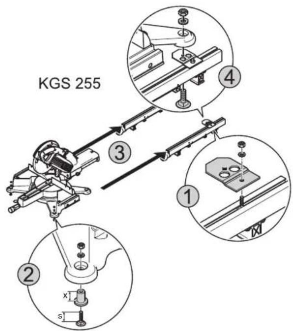
| x (mm) s (mm) | ||
| KS 210 Lasercut 22 55 | ||
| KGS 255 16 40 | ||
| KGS 303 22 40 | ||
| KGT 300 22 40 | ||
| KGS 301/331 22 40 | ||
| KGS 305 26 40 | ||
| KS 216 (M) Lasercut – 25 | ||
| KGS 216 (M) – 32 | ||
| KGS 254 (M) – 32 | ||
| KS 254 Plus – 32 | ||
| KS 305 Plus – 32 | ||
| KGS 216 Plus – 32 | ||
| KGS 254 I Plus – 32 | ||
| KGS 254 Plus – 32 | ||
| KGS 315 Plus – 32 | ||
19
20
natural_image
Mechanical device labeled 'metabo' with a close-up inset showing a lock mechanism (no text beyond label)21
natural_image
Silhouette of a person pushing a wheeled cart with directional arrows indicating motion (no text or symbols)23
natural_image
Silhouette of a person pushing a cart with mechanical components (no text or symbols visible)22
natural_image
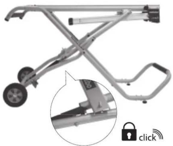
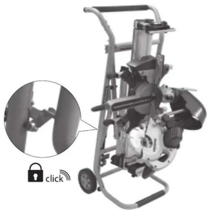
Mechanical device with a lock icon and 'click' annotation, showing internal components and a close-up of a mechanical component (no readable text or symbols)
Marque : METABO
Modèle : KSU 250 Mobile
Catégorie : Support d'outil électrique