
CM876GDW6S - Plaque de cuisson SIEMENS - Notice d'utilisation et mode d'emploi gratuit
Retrouvez gratuitement la notice de l'appareil CM876GDW6S SIEMENS au format PDF.
| Type de produit | Four encastrable |
| Marque | Siemens |
| Modèle | CM876GDW6S |
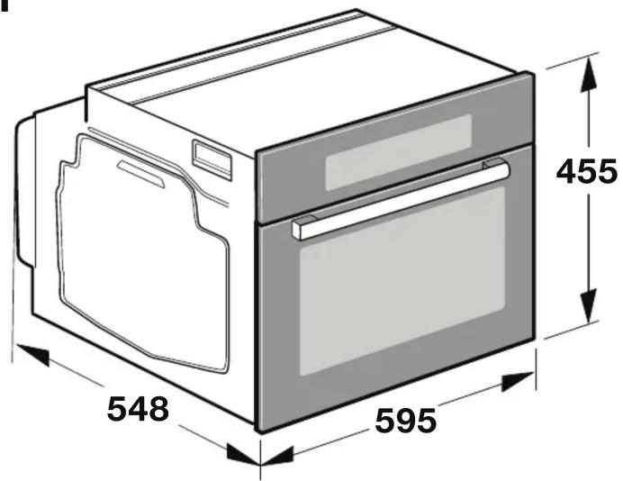
| Dimensions (H x L x P) | 595 mm x 596 mm x 548 mm |
| Dimensions de la niche d'encastrement (H x L x P) | 590 mm x 560 mm x 550 mm |
| Alimentation électrique | 220-240 V, 50/60 Hz, classe de protection I |
| Raccordement | Câble d'alimentation fourni, prise avec terre ou sectionneur omnipolaire |
| Capacité du four | Environ 71 L (estimation) |
| Fonctions de cuisson | Chaleur tournante, convection naturelle, gril, pyrolyse (selon modèle) |
| Matériau de la cavité | Acier émaillé |
| Nettoyage | Pyrolyse ou nettoyage manuel avec chiffon humide et détergent doux |
| Sécurité | Protection contre les surchauffes, verrouillage de porte, distance minimale de 10 cm pour porteurs d'implants électroniques |
| Installation | Encastrable sous plan de travail ou dans une colonne, nécessite une ventilation adéquate |
| Poids net | Environ 35 kg (estimation) |
FOIRE AUX QUESTIONS - CM876GDW6S SIEMENS
Questions des utilisateurs sur CM876GDW6S SIEMENS
0 question sur cet appareil. Repondez a celles que vous connaissez ou posez la votre.
Poser une nouvelle question sur cet appareil
Téléchargez la notice de votre Plaque de cuisson au format PDF gratuitement ! Retrouvez votre notice CM876GDW6S - SIEMENS et reprennez votre appareil électronique en main. Sur cette page sont publiés tous les documents nécessaires à l'utilisation de votre appareil CM876GDW6S de la marque SIEMENS.
MODE D'EMPLOI CM876GDW6S SIEMENS
en
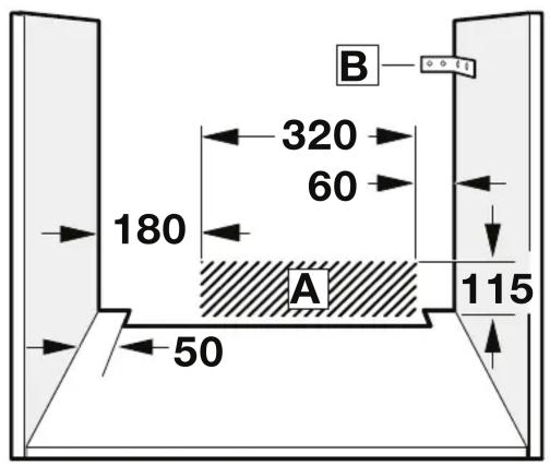
Important information – Fig. 1
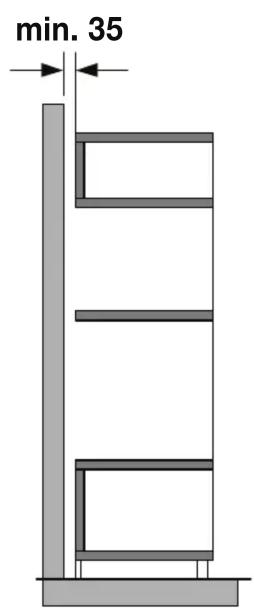
The fitted cabinet must not have a back panel behind the appliance. There should be a gap of at least 35 mm wall and the cabinet base as well as the rear panel that is situated above.
The fitted cabinet must have a ventilation opening of 50 cm^2 on the front. On conversion units without a ventilation must be a ventilation opening of 200 cm^2 towards side panels. To do this, trim the base panel or fit a ventilation grille.
■ Ventilation slots and intakes must not be covered.
- Check the appliance for damage after unpacking it. Do not connect the appliance if it has been damaged in transit.
■ Before starting up the appliance, remove any packaging and adhesive film from the cooking compartment and the door.
■ Fitted units must be heat-resistant up to 90 °C, and adjacent unit fronts up to 70 °C.
- Do not install the appliance behind a decorative panel. There is a risk of overheating.
■ Any cut-outs that need to be made in the units should be made before the appliance is installed. Remove any shavings as they may prevent the electrical components from working properly.
■ Wear protective gloves so that you do not cut yourself are accessible during installation may have sharp edges.
For appliances that have a hinged switch panel, make sure that the switch panel does not hit adjacent kitchen units when you open it.
■ The power socket for the appliance must either be hatched area A or outside of the area where the appliance is installed.
- Secure any unsecured units to the wall using a s B.
■ The dimensions in the figures are in mm.
⚠️ Wearers of electronic implants!
The appliance may contain permanent magnets which may affect electronic implants, e.g. heart pacemakers or insulin pumps. Therefore, during installation, wearers of electronic implants must maintain a minimum distance of 10 cm from the appliance.
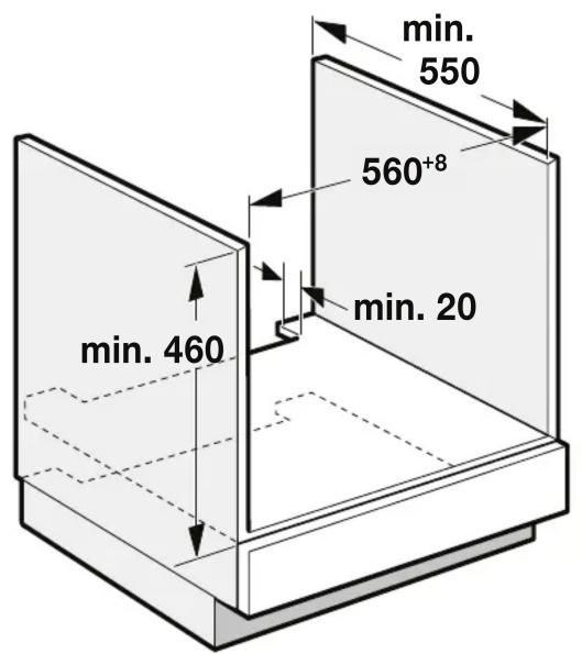
Appliance under worktop – Fig. 2
To ventilate the appliance, the intermediate floor must have a ventilation cut-out.
Secure the worktop to the fitted units.
If the appliance is installed under a hob, the following minimum dimensions must be adhered to (including substructure, if applicable):
Hob type a
a
Fixed
b
Flush with sur- rounding sur- faces
Induction hob 42 mm 43 mm 5 mm
Full-surface induction48 mm 53 mm 5 mm hob
Gas hob 37 mm 47 mm 5 mm
Electric hob 28 mm 30 mm 2 mm
The minimum worktop thickness a results from the minimum required dimension b.
Observe the installation instructions for the hob.
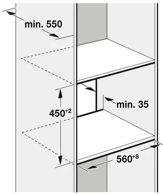
Appliance in a tall unit - Fig. 3
To ventilate the appliance, the intermediate floors must have a ventilation cut-out.
If the tall unit has another back panel in addition to the element between the back panels, this must be removed.
Only fit the appliance up to a height which allows access easily removed.
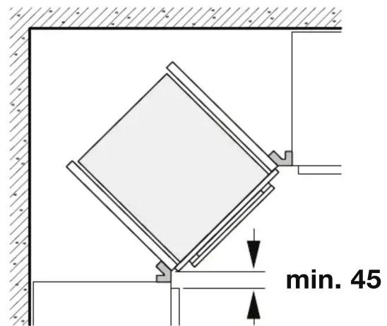
cut-out corner installation – Fig. 4
To ensure that the appliance door can be opened in a corner installation, take account of dimension C. Dimension D is dependent on the thickness of the unit front under the handle.
Connecting the appliance
The appliance corresponds to protection class 1 and must operate with a protective earth connection.
The fuse protection must correspond to the power rating s on the appliance's rating plate and to local regulations.
The appliance must be disconnected from the power supply whenever installation work is being carried out.
The appliance must only be connected with the power cable provided. Connect the power cable to the back of the appliance (listen for the click).
A 3 m power cable can be obtained from the after-sales service.
If The Padvertable must only be replaced with a cable from the original manufacturer, which can be obtained from the after-sales service.
When the appliance is installed, protection must be provided against accidental contact in the future.
located in the Power cable with a plug with earthing contact
The appliance must only be connected to a properly installed protective contact socket.
If the plug is no longer accessible following installation, an isolating switch must be present on the installation side with a contact gap of at least 3 mm.
Power cable without a three-pin earthed plug
The appliance must only be connected by a licensed professional.
The installation must have an all-pole isolating switch with a contact gap of at least 3 mm. Identify the live and neutral conductors in the mains socket. The appliance may be done, it is not connected correctly.
Only connect the hob as shown in the connection diagram. See the rating plate for the voltage. Connect the wires of the mains power cable according to the colour coding: Green/yellow = PE conductor <, blue = neutral conductor, brown = live (external conductor).
Only in Sweden, Finland and Norway
The appliance can also be connected using the plug provided which has an earthing contact system. This must still be accessible after installation. If this is not the case, an all-pole isolating switch must be used on the installation side with gap of at least 3 mm.
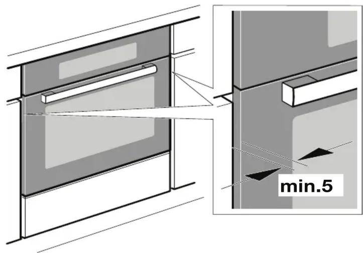
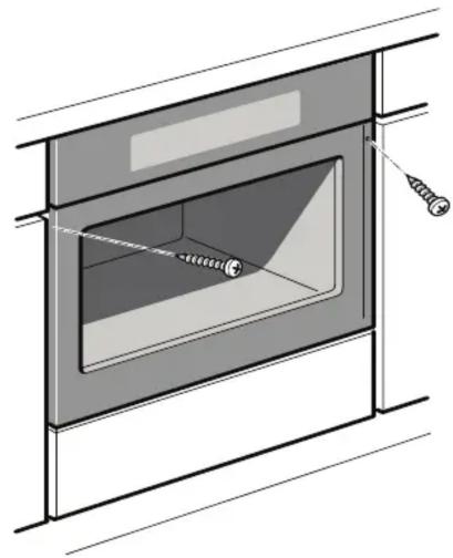
Securing the appliance – Fig. 5
-
Fully insert the appliance and centre it.
-
Screw the appliance into place.
The gap between the worktop and appliance must not be sealed by additional strips.
Thermal insulation strips must not be fitted to the side panels of the surround unit.
Removal
- Disconnect the appliance from the power supply.
- Undo the securing screws.
- Lift the appliance slightly and then pull it out completely.
الحد الأدنى لسمك سطح العمل a ينتج عن الحد الأدنى للمسافة المطلوبة b
تراعى التعليمات الخاصة بتركيب الموقد.
تث EIET الجهاز في وحدة عالية - شكل 3
لغرض tweوية الجهان، يجب وجود فتحة tweوية بالأرضيات البينية.
إذا كانت الوحدة العالمية مشتملة على لوح خلفي أخرىであضاءة إلى الألواح الخلافية
الأساسية، فإنه يجب خلع هذا اللوح الخلافي.
قم burdensكيب الجهاز على ارتفاع يسمح باExpected الكماليات بسهولة.
التركيب في أحمد الأركان - شكل 4
لضمان إمkanية فتح باب الجهاز عند التركيب في أحمد الأركان، التزم بالمسافة C.
المسافة D تتوقف على سُمّك واجهة الوحدة أَسفل المقبض.
توصيل الجهاز
الجهاز متوافق مع فئة الحماية 1 ولا يجوز تشغيله إلا في حالة وجود وصلة حماية
أرضية.
يجب أن يكون مصر الحماية مطابقا للقدرة الاسمية المقررة بلوحة صنع الجهاز
ومطابقا للتشيعات المحلية.
يجب فصل الجهاز عن مصر الإمداد بالتيار عند إجراء أعمال التركيب.
يجب توصيل الجهاز بكابل الكهرباء المورد فقط. قم بتوصيل كابل الكهرباء بظهر
الجهاز (ي ثبت ب صوت كليك مسموع).
يمكن الحصول على كامل كهرباء 3 م من مركز خدمة ما بعد البيع.
يجب استبidal كابل الكهرباء بكابل كهرباء من الجheitة الصانعة الأصلية فقط والذي
يمكن الحصول عليه من مركز خدمة ما بعد البيع.
عندما يتم تركيب الجهان، يجب تزويده فيما بعد بوسيلة حماية ضد التلامس غير
المقصود.
کابل کهرباء مزود ب tapeس بملامس أرضي
لا يجوز توصيل الجهاز إلا بمقبس مركب بشكل صحيع ومزود بوصلة حماية.
إذا لم يعد بالامكان الوصول إلى القابس بعد التركيب، فيجب أن يكون هناك مفتاح
فصل لجميع الأقطاب على جانب التركيب بفجوة تلامس مقدارها 3 meg على الأقل.
كابل كهربائي بدون قابس مؤرض ثلاثي السنون
يجب توصيل الجهاز عن طريق فني معتمد فقط.
يجب أن يشتمل التركيب على مفتاح فصل لجميع الأقطاب بفجوة تلامس تبلغ 3 Swiss على الأقل. قم بتحديد الأسلاك الموصلة لل.ceرباء وأسلامال المحايدة في مقبس ال山坡كة الكهربائية. قد يتعرض الجهاز للضر Ir Estonia لم يتم“Toصيله بشكل صحيم. قم بتوصيل الموقد seating كما هو Cordign في مخطت التوصيل. انظر لOutcome الصنع معرفة قيمة Ganهد الكهربائي. قم بتوصيل أسلامك كابل الكهرباء طبقا للترMIز اللوي: أخضر/أ Safari = سلك PE; أزرق = سلك محايد، بني = موصل للTYار
( Castle خارجي .
فقط في السيد وفنلندا والنROIچ
يمكن أيضا توصيل الهاز باستخدم القابس المورد المشتمل على نظام توصيل مおります.名义 أن يظل الوصول إلىه متاحا بعد التركيب. إذا لم يكن الحال ذلك, فيجب استخدام مفتاح فصل لجميع الأقطاب بمكان التركيب بفجوة تلامس لا تقل
عن 3 مم.
تأمين الجهاز - شكل 5
-
أدخل الجهاز فيunded المخصص له حتىDEPTH وقدم بمركزته.
-
اربط الجهاز بالبراغي في /.
لا يجوز سد الفجوة بين سطح العمل والجهاز باستخدم أشرطة إضافية.
يحظر تركيب أشرطة عزل حرارية بالألواح الجانبية للوحدة المحيطة.
ال Falk
-
افصل الجهاز عن مصر الإ cards بالتيار.
-
قم بфик براغي تأمين الجهان.
-
ارفع الجهاز قليلا ثم اسببه للخارج بالكامل.
ar
إرشادات مهمة - شكل 1
يجب أن تكون الخزanine المركبة غير مزودة بلوح خلفي وراء الجهان. ينبغي أن
お願いいたします 35 مم على الأقل بين الجدار وقاعدة孵化器 وكذك بين
اللوح الخلفي للخزانة المركبة أعلاه.
كما يجب أن تشتمل الخزanine المركبة على فتحة}// تهوية تبلغ 50 سم ^2 بالأمام. عند
التركيب على وحدات تحويل غير مزودة بفتحة蓮وية، يجب توفير فتحة蓮وية
تبلغ 200 سم ^2 تجاه الجانب الخلفي من الألواح الجナンية. ولقيام بذلك، اقطع
جزءً من اللوحة السفيلة أو قم بتركيب شبكة تهوية.
لتهوية.
تحفق من عدم وجود أضرار بالجهاز بعد إخراجه من عبوة التغليف. ولا تقم
بتوصيل الجهاز في حالة اكتشف أضرار ناتجة عن عملية النقل.
احرص قبل بدء تشغيل الجهاز على إزالة关键技术 مواد تغليف أو رقائق لاصقة من
حيز الطهي أو الباب.
يجب أن تكون الوحدات المركبة مقاومة للحرارة حتى 90°م، وواجهات الوحدات
المج Cooperative حتى 70°م.
لا تقم بتركيب الجهاز وراء لوح زينة. فهناك خطر التعرض لسخونة مفرطة.
ينبغي عمل أية قطوعات لازمة في الوحدات قبل تركيب الجهاز. تخلص من أية
نشارة أو برادة موجودة، حيث أنها قد تعيق عمل الأجزاء الكهربائية بشكل صحيح.
ارتد قفازات واقية لكي لا تجرح نFKSK. الأجزاء التي يمكن إدخال اليد فيها أثناء
التركيب قد تكون حادة الحواف.
بالنسبة للأجهزة المشتملة على لوحة مفاتيح مفصلية، تأكد من عدم ارط Imam
لوحة المفاتيح بوحدات المطبخ Mojzcورة أثناء فتحها.
يجب أن يكون المقبس الكهربائي للجهاز إما في المنطقة المظللة Ⓐ أو خارج
المنطقة التي يتم فيها تركيب الجهان.
B. قم Combined أية وحدات غير مؤمنة بال-theار باستخدم الرياضة
الأبعاد الواردة في الأشكال مقاسة بوحدة مم.
⚠️ الأشخاص الحاملون لأجهزة طبية exponentially مزروعة!
قد يحتوى الجهاز على قطع مغناطيسية دائمة تؤثر على الأجهزة الطبية الإلكترونية
المزروعة في الجسم، مثل أجهزة تنظيم ضربات القلب أو مضخات الأنسولين. لذلك،
يجب على الأ рассказ الحاملين لأجهزة طبية eccentricية مزروعة في أجسامهم
الhfاظ على مسافة لا تقل عن 10 سم من الجهان.
الجهاز تحت سطح العمل - شكل 2
لغرض tweوية Jinghaz، يجب وجود فتحة tweوية بالأرضية الصينية.
قم بتأمين سطح العمل بالوحدات المركبة.
إذا تم تركيب Jingاز أسفل موقد، فيجب الالترزم بأدنى حد للمسافات التالية
(شاملة الهيكل السفلي إن وجد)
b a نوع الموقد
متحاني مع الأسطح المحيطة ثالث
| 5 | 43 | 42 | م咱ق د حثي |
| 5 | 53 | 48 | م咱ق د حثي للتركيب علىالسطح باكمله |
| 5 | 47 | 37 | م咱ق د غازي |
| 2 | 30 | 28 | م咱ق د كهربائي |
4
5
natural_image
Technical line drawing of a window with screw fasteners inserted, no text or symbols present1
2
3

- en
- Important information – Fig. 1
- ⚠️ Wearers of electronic implants!
- Appliance under worktop – Fig. 2
- Appliance in a tall unit - Fig. 3
- cut-out corner installation – Fig. 4
- Connecting the appliance
- located in the Power cable with a plug with earthing contact
- Power cable without a three-pin earthed plug
- Only in Sweden, Finland and Norway
- Securing the appliance – Fig. 5
- Removal
- توصيل الجهاز
- ar
- إرشادات مهمة - شكل 1
Marque : SIEMENS
Modèle : CM876GDW6S
Catégorie : Plaque de cuisson