CS656GBS6B - Plaque de cuisson SIEMENS - Notice d'utilisation et mode d'emploi gratuit
Retrouvez gratuitement la notice de l'appareil CS656GBS6B SIEMENS au format PDF.

| Caractéristiques techniques | Détails |
|---|---|
| Type d'appareil | Four encastrable |
| Capacité | 71 litres |
| Type de cuisson | Chaleur tournante, grill, cuisson traditionnelle |
| Classe énergétique | A+ |
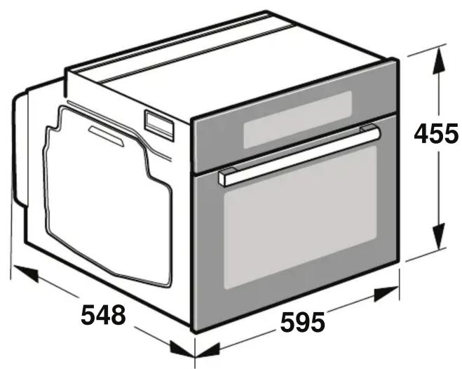
| Dimensions (HxLxP) | 59,5 x 59,4 x 54,8 cm |
| Poids | 35 kg |
| Fonctionnalités supplémentaires | Nettoyage par catalyse, affichage numérique |
| Utilisation | Idéal pour la cuisson de plats variés, facile à utiliser avec des commandes intuitives. |
| Maintenance | Nettoyage régulier recommandé, vérification des joints et des éléments de chauffage. |
| Sécurité | Protection contre la surchauffe, porte froide pour éviter les brûlures. |
| Informations générales | Garantie de 2 ans, service après-vente disponible. |
FOIRE AUX QUESTIONS - CS656GBS6B SIEMENS
Questions des utilisateurs sur CS656GBS6B SIEMENS
0 question sur cet appareil. Repondez a celles que vous connaissez ou posez la votre.
Poser une nouvelle question sur cet appareil
Téléchargez la notice de votre Plaque de cuisson au format PDF gratuitement ! Retrouvez votre notice CS656GBS6B - SIEMENS et reprennez votre appareil électronique en main. Sur cette page sont publiés tous les documents nécessaires à l'utilisation de votre appareil CS656GBS6B de la marque SIEMENS.
MODE D'EMPLOI CS656GBS6B SIEMENS
en
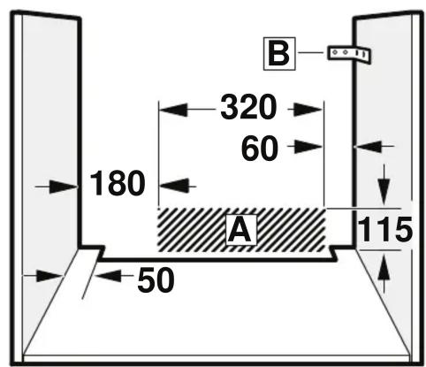
Important information - Fig. 1
This appliance is intended for use up to a maximum height of 2000 metres above sea level.
The safe operation of this appliance can only be has been installed to a professional standard in a these installation instructions. The installer shall be liable for damages incurred as a result of incorrect installation.
Check the appliance for damage after unpacking it. Do not connect the appliance if it has been damaged in transit.
Before starting up the appliance, remove any packaging and adhesive film from the cooking compartment and the door.
Fitted units must be heat-resistant up to 90^ , and adjacent unit fronts up to 70^ .
- Do not install the appliance behind a decorative panel. There is a risk of overheating.
- Any cut-outs that need to be made in the units should be made before the appliance is installed. Remove any shavings as they may prevent the electrical components from working properly.
- Wear protective gloves so that you do not cut yourse are accessible during installation may have sharp edges.
For appliances that have a hinged switch panel, make sure that the switch panel does not hit adjacent kitchen units when you open it.
The power socket for the appliance must either be hatched area A or outside of the area where the appliance is installed.
- Secure any unsecured units to the wall using a s B.
The dimensions in the figures are in mm.
Wearers of electronic implants!
The appliance may contain permanent magnets which may affect electronic implants, e.g. heart pacemakers or insulin pumps. Therefore, during installation, wearers of electronic implants must maintain a minimum distance of 10cm from the appliance.
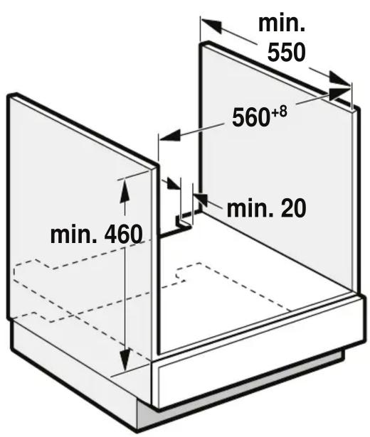
Appliance under worktop - Fig. 2
To ventilate the appliance, the intermediate floor must have a ventilation cut-out.
Secure the worktop to the fitted units.
If the appliance is installed under a hob, the following minimum dimensions must be adhered to (including substructure, if applicable):
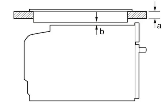
Induction hob 42 mm 43 mm 5 mm
Full-surface induction48 mm 53 mm 5 mm hob
Gas hob 37 mm 47 mm 5 mm
Electric hob 28 mm 30 mm 2 mm
The minimum worktop thickness a results from the minimum required dimension b.
Observe the installation instructions for the hob.
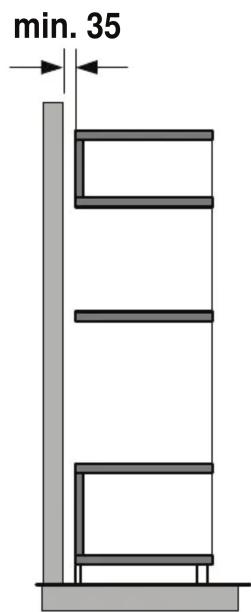
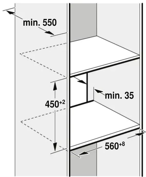
Appliance in a tall unit - Fig. 3
To ventilate the appliance, the intermediate floors must have a ventilation cut-out.
If the tall unit has another back panel in addition to the element back panels, this must be removed.
Only fit the appliance up to a height which allows access to the oven.
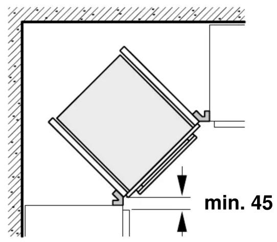
Corner installation - Fig. 4
To ensure that the appliance door can be opened in a corner installation, take account of dimension C. Dimension D is dependent on the thickness of the unit front under the handle.
Controlling the appliance
The appliance corresponds to protection class 1 and must operate with a protective earth connection.
The fuse protection must correspond to the power rating s on the appliance's rating plate and to local regulations.
The appliance must be disconnected from the power supply whenever installation work is being carried out.
The appliance must only be connected with the power cable provided. Connect the power cable to the back of the appliance (listen for the click).
A 3 m power cable can be obtained from the after-sales service. The power cable must only be replaced with a cable from the
original manufacturer, which can be obtained from the after-sales service.
cated in the When the appliance is installed, protection must be provided against accidental contact in the future.
Powergate with a plug with earthing contact
The appliance must only be connected to a properly installed protective contact socket.
If the plug is no longer accessible following installation, an isolating switch must be present on the installation side with a contact gap of at least 3 mm.
Power cable without a three-pin earthed plug
The appliance must only be connected by a licensed professional.
The installation must have an all-pole isolating switch with a contact gap of at least 3mm . Identify the live and neutral conductors in the mains socket. The appliance may be dated it is not connected correctly.
Only connect the hob as shown in the connection diagram. See the rating plate for the voltage. Connect the wires of the mains power cable according to the colour coding: Green/yellow = PE conductor 12 , blue = neutral conductor, brown = live (external conductor).
Only in Sweden, Finland and Norway
The appliance can also be connected using the plug provided which has an earthing contact system. This must still be accessible after installation. If this is not the case, an all-pole isolating switch must be used on the installation side with gap of at least 3 mm.
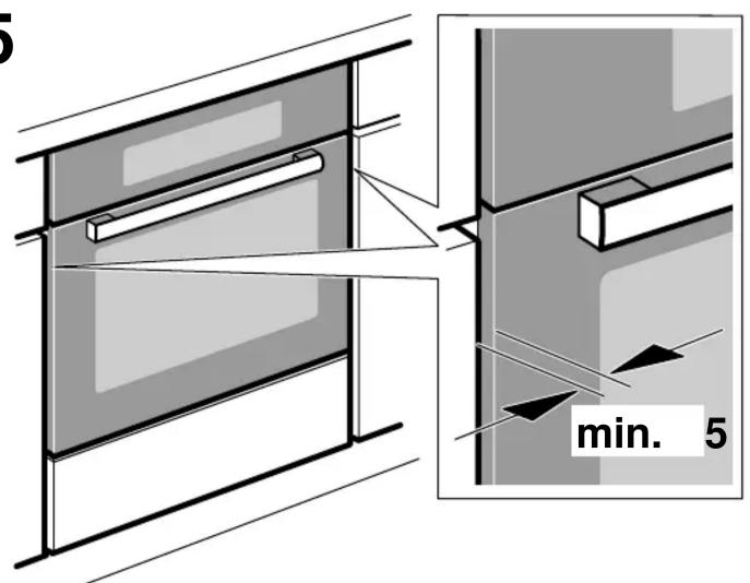
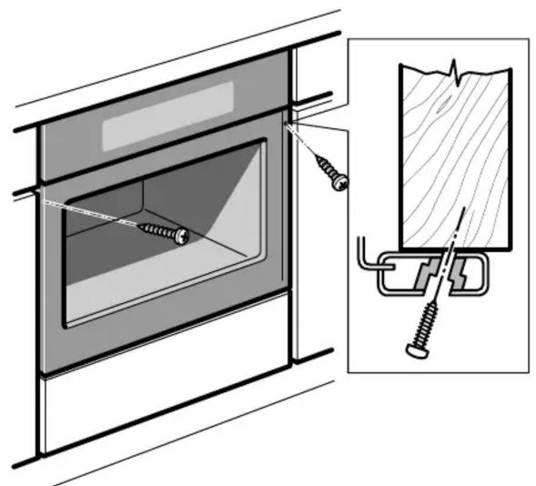
Securing the appliance - Fig. 5
-
Fully insert the appliance and centre it.
-
Screw the appliance into place.
The gap between the worktop and appliance must not be sealed by additional strips.
Thermal insulation strips must not be fitted to the side panels of the surround unit.
Removal
- Disconnect the appliance from the power supply.
- Undo the securing screws.
- Lift the appliance slightly and then pull it out completely.
3 0g- aaiy aaij jgl
a a a a a a a a a a a a a a a a a a a a a a
aallll jnll lulss
y
aIgss sll lss
4o-+jLj
sLey 1e jckj kJd JgKjll djc yol jy
jL
J 1 1
e aagglge gaaagaaaegaaagaaagaaagaaagaaagaaagaaagaaagaaagaaagaaagaaagaaagaaagaaagaaagaaagaaagaaagaaagaaagaaagaaagaaagaaagaaagaaagaaagaaagaaagaaagaaagaaagaaagaaagaaagaaagaaagaaagaaagaaagaa
all
a
JLK JUSSIJIa. 100000000000000000000000000000000000000000
(1)
3.0 Jb bJy 1yL yIa
a 1
x1 = 2,x2 = - 4
.
JU 1 JU
J 1
y
p03 1 Jai y wdi s jy bdi jdi jdi
Jg Jg Jg Jg Jg Jg Jg Jg Jg
Jaae 1
s
()dallgogolglalagogog
j 1
aagl jaiy yg 11 g aiaa baaal baaal baaal
ailll joljoljoljoljoljoljoljoljoljoljoljoljoljoljolj
111=(j)(j)(j)
(20 1
g jllg ggl
y
a 1 1 1 1 1 1 1 1 1 1 1 1 1 1 1 1
3 2 1 0 0 0 0 0 0 0 0 0 0 0 0
5a-14
aJgS JgSlljgl .1
14.25
aLl a bJbJbJbJbJbJbJbJbJbJbJbJbJb
a aai jai jai jai jai jai jai jai jai jai jai jai jai jai jai jai jai jai jai jai jai jai jai jai jai jai jai jai jai jai jai jai jai jai jai jai jai jai jai jai jai jai jai
j1i jie 11 jll
Lolai 111 111 111 111 1.3
ar
1 a-g-aa
2000 1
a
jll jll jll jll jll jll jll jll jll jll jll jll jll jll jll jll jll jll jll jll jll jll jll jll jll jll jll jll jll jll jll jll jll jll jll
a
Jdll 1a e a jilj
Jg Jg j 1
- i.e., 11
aagalol 90 giaagaae aee
070 1
a
aBjdo all jgdo
ailljbj jglll jkssj jbbal lal
aLgS11 1j2u 1s11 1s11 1c Ls jdd,oo
lll jaiy i yj 1i j 1i j 1i j 1i j 1i j
aagaae aee
1 1
1 1
J A aalllalalalalalalalalalalalalalalalalal
sjjillabibio jbbi
aagaiial aajllal aaiiuiu laall gaaiaaiail aie baiaiai
B l_g^_g
.
aegjoll aall aagjgsl 1y jolal
j0g j1 1c Ls Jg Sd aaiu aabolio g bS cJgall
y
10 10 10
aagjzall aalb alg jy
2 oJ - Jaaall jawj j
a a a a a a a a a a a a a a a a a a a a a
s jll sddg lce Jdell cii
Xolw) aJlll l jlll Jyjll Jyjll
:
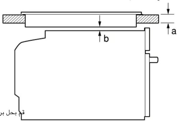
b
a
gaj a
jlaa 1
jL
cbull 2a cbull
5 43 42
5 53 48
cbullolcs
5 47 37 jLg
2 30 28
clawdow jdl llll wjckb oJU Uaalwll
a JaaJI
aagall 5 jJ Jg

4
5

1
2
3