CR676G0S3 - Plaque de cuisson SIEMENS - Notice d'utilisation et mode d'emploi gratuit
Retrouvez gratuitement la notice de l'appareil CR676G0S3 SIEMENS au format PDF.

| Caractéristiques Techniques | Détails |
|---|---|
| Type d'appareil | Non catégorisé |
| Dimensions | Non spécifiées |
| Poids | Non spécifié |
| Capacité | Non spécifiée |
| Consommation énergétique | Non spécifiée |
| Fonctionnalités supplémentaires | Non spécifiées |
| Utilisation | Non spécifiée |
| Maintenance | Non spécifiée |
| Sécurité | Non spécifiée |
| Informations générales | Non spécifiées |
FOIRE AUX QUESTIONS - CR676G0S3 SIEMENS
Questions des utilisateurs sur CR676G0S3 SIEMENS
0 question sur cet appareil. Repondez a celles que vous connaissez ou posez la votre.
Poser une nouvelle question sur cet appareil
Téléchargez la notice de votre Plaque de cuisson au format PDF gratuitement ! Retrouvez votre notice CR676G0S3 - SIEMENS et reprennez votre appareil électronique en main. Sur cette page sont publiés tous les documents nécessaires à l'utilisation de votre appareil CR676G0S3 de la marque SIEMENS.
MODE D'EMPLOI CR676G0S3 SIEMENS
en
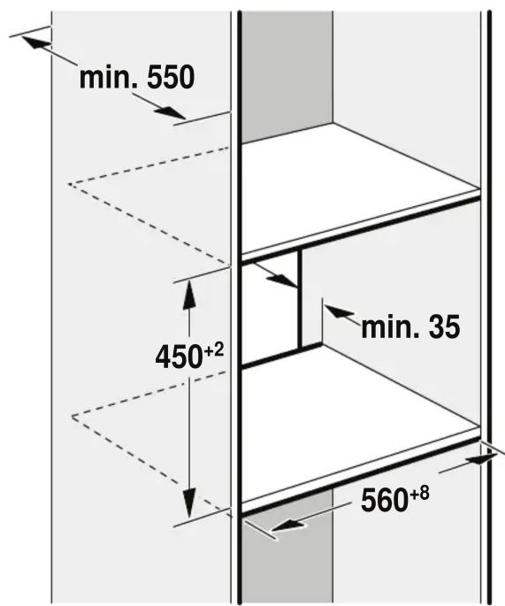
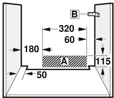
Important information – Fig. 1
This appliance is intended for use up to a maximum height of 2000 metres above sea level.
The safe operation of this appliance can only be has been installed to a professional standard in a these installation instructions. The installer shall be liable for damages incurred as a result of incorrect installation.
- Check the appliance for damage after unpacking it. Do not connect the appliance if it has been damaged in transit.
■ Before starting up the appliance, remove any packaging and adhesive film from the cooking compartment and the door.
■ Fitted units must be heat-resistant up to 90 °C, and adjacent unit fronts up to 70 °C.
- Do not install the appliance behind a decorative panel. There is a risk of overheating.
■ Any cut-outs that need to be made in the units should be made before the appliance is installed. Remove any shavings as they may prevent the electrical components from working properly.
■ Wear protective gloves so that you do not cut yourse are accessible during installation may have sharp edges.
For appliances that have a hinged switch panel, make sure that the switch panel does not hit adjacent kitchen units when you open it.
■ The power socket for the appliance must either be hatched area A or outside of the area where the appliance is installed.
- Secure any unsecured units to the wall using a stand B.
■ The dimensions in the figures are in mm.
⚠️ Wearers of electronic implants!
The appliance may contain permanent magnets which may affect electronic implants, e.g. heart pacemakers or insulin pumps. Therefore, during installation, wearers of electronic implants must maintain a minimum distance of 10 cm from the appliance.
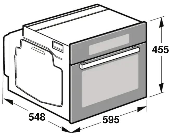
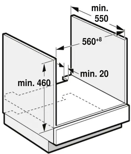
Appliance under worktop – Fig. 2
To ventilate the appliance, the intermediate floor must have a ventilation cut-out.
Secure the worktop to the fitted units.
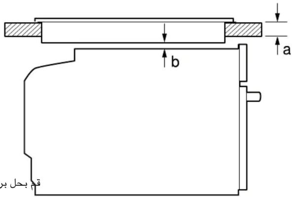
If the appliance is installed under a hob, the following minimum dimensions must be adhered to (including substructure, if applicable):
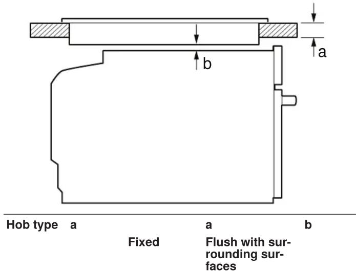
Induction hob 42 mm 43 mm 5 mm
Full-surface induction48 mm 53 mm 5 mm hob
Gas hob 37 mm 47 mm 5 mm
Electric hob 28 mm 30 mm 2 mm
The minimum worktop thickness a results from the minimum required dimension b.
Observe the installation instructions for the hob.
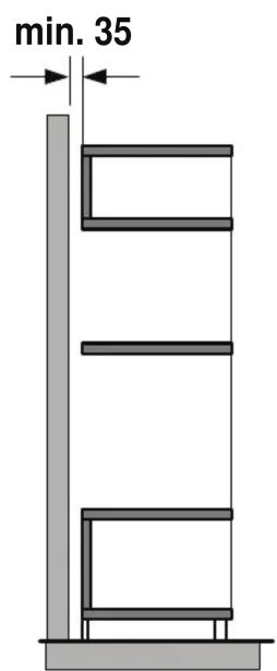
Appliance in a tall unit - Fig. 3
To ventilate the appliance, the intermediate floors must have a ventilation cut-out.
If the tall unit has another back panel in addition to the element back panels, this must be removed.
Only fit the appliance up to a height which allows access granted if it easily removed.
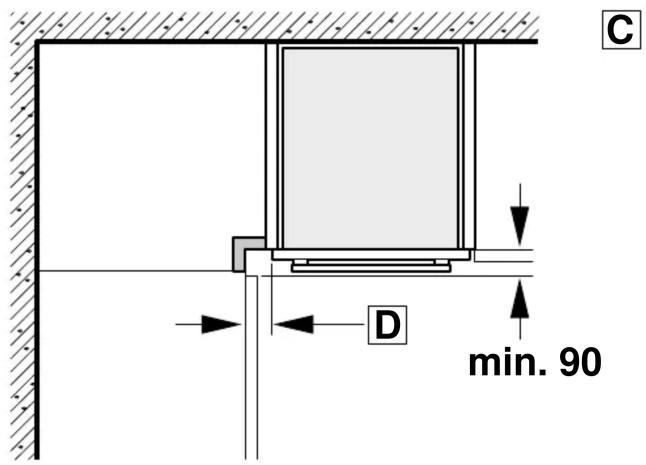
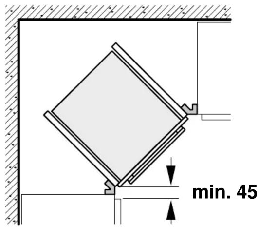
Corner installation – Fig. 4
To ensure that the appliance door can be opened in a corner installation, take account of dimension C. Dimension D is dependent on the thickness of the unit front under the handle.
Connecting the appliance
The appliance corresponds to protection class 1 and must operate with a protective earth connection.
The fuse protection must correspond to the power rating s on the appliance's rating plate and to local regulations.
The appliance must be disconnected from the power supply whenever installation work is being carried out.
The appliance must only be connected with the power cable provided. Connect the power cable to the back of the appliance (listen for the click).
A 3 m power cable can be obtained from the after-sales service. The power cable must only be replaced with a cable from the original manufacturer, which can be obtained from the after-sales service.
located in the When the appliance is installed, protection must be provided against accidental contact in the future.
Power cable with a plug with earthing contact
The appliance must only be connected to a properly installed protective contact socket.
If the plug is no longer accessible following installation, an isolating switch must be present on the installation side with a contact gap of at least 3 mm.
Power cable without a three-pin earthed plug
The appliance must only be connected by a licensed professional.
The installation must have an all-pole isolating switch with a contact gap of at least 3 mm. Identify the live and neutral conductors in the mains socket. The appliance may be done, it is not connected correctly.
Only connect the hob as shown in the connection diagram. See the rating plate for the voltage. Connect the wires of the mains power cable according to the colour coding: Green/yellow = PE conductor 12 , blue = neutral conductor, brown = live (external conductor).
Only in Sweden, Finland and Norway
The appliance can also be connected using the plug provided which has an earthing contact system. This must still be accessible after installation. If this is not the case, an all-pole isolating switch must be used on the installation side with gap of at least 3 mm.
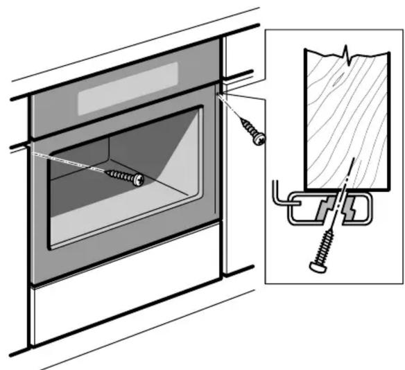
Securing the appliance – Fig. 5
-
Fully insert the appliance and centre it.
-
Screw the appliance into place.
The gap between the worktop and appliance must not be sealed by additional strips.
Thermal insulation strips must not be fitted to the side panels of the surround unit.
Removal
- Disconnect the appliance from the power supply.
- Undo the securing screws.
- Lift the appliance slightly and then pull it out completely.
الجهاز في خزanine مرتفعة - صورة 3
لغرض tweوية الجهاز يجب أن تتوفر بالأرضيات البينية فتحة قطعية للthesize.
إذا كانت الخزanine المرتفعة بها جدار خلفي إضافي فضلا عن الجدران الخلفية
الاساسية، فيجب خلع هذا الجدار الإضافي.
قم burdensكيب الجهاز على ارتفاع يسمح باخراج الكماليات بسهولة.
التركيب في أحمد الأركان - صورة 4
كي يتسنى فتح باب الجهان، احرص عند التركيب في أحمد الأركان على مerationة
المقياس C. ويت十四五 المقياس D على سiek واجهة وحدة المطبخ أسفل المقبض.
توصيل الجهاز
الجهاز مطابق لفئة الحماية 1 ولا يجوز تشغيله إلا في ظل التوصيل بموصل أرضي.
ويجب أن تتم عملية التأمين بالمصر وفقا لبيان القدرة المدون على لوحة الصنع
وببقا للوائح المحلية.
يجب فصل التيار عن الجهاز أثناء إجراء جميع أعمال التركيب.
يجب توصيل الجهاز باستخدم كابل التوصيل المورد فقط. قم بتوصيل كابل
التوصيل بالجهة الخلفية للجهاز (صوت كليك!)
يتوفر لدى خدمة العملاء كابل توصيل بطول 3,0 م.
لا يجوز استبidal كابل التوصيل إلا بكابل أصلي، يمكن الحصول عليه من خدمة
العملاء.
يجب أن تضمن عملية التركيب الحماية من حدوث تلامس.
كابل التوصيل بقابس مزود بموصل أرضي
لا يجوز توصيل هذا小微企业 إلا بمقبس مóriaض ومرکب بشكل صحیح.
في حالة تعذر الوصول إلى القابس بعد التركيب يجب أن يتوافر في /.موع التركيب
تجهيئة فصل لجميع الاقطاب بفجوة تلامس لا تقل عن 3 مم.
كابل التوصيل بدون قابس مزود بموصل أرضي
لا يجوز توصيل الجهاز إلا من قبل فني معتمد.
أثناء التركيب، يجب أن يكون هناك مفتاح فصل لجميع الأقطاب بفتحة تلامس
لا تقل عن 3 مم. ويجب تحديد موصل الطور والموصل المحايد («صفر») بمقبس
التوصيل. فقد تلحق أضرار بالجهاز في حالة توصيله بشكل خاطى.
قم بالتوصيل وفقا لمخطال التوصيل فقط. لمعرفة الجهد الكهربائي انظرلوحة
الصنع. قم بتوصيل أسلاك كابل التوصيل بالشبكة طبقا لأكواد الألوان التالية:
أخضر - أصفر = موصل أرضي (١) ، أزرق = (صفر) موصل محايد، بني = الطور
(موصل خارجي).
فقط في السيد وفنندا والنROIچ
يمكن توصيل الجهاز أيضا باستخدام القابس المرفق المزود بنظام تأريض. ويجب
أن يظل بالإمكان الوصول إلىه بعد التركيب. إذا لم يكون الحال كذلك، فيجب مرة
أخرى استخدام مفتاح فصل لجميع الاقطاب بفتحة تلامس لا تقل عن 3 мм في
موقع التركيب.
تثبيت الجهاز - صورة 5
-
أدخل الجهاز بالكامل وقم بمركزته.
-
أحكم ربط براغى الجهاز.
لا يجوز إحكام غلق الفجوة بين سطح العمل والجهاز بواسطة أشرطة إضافية.
ولا يجوز تركيب أشرطة عزل حراوي بالゲدران الج antibodies للخزanine المحيطة.
ال Falk
-
افصل التيار الكهربائي عن الجهاز.
-
ارفع الجهاز قليلا واسحبه للخارج تماما
-
بحل براغي التثبيي.
إرشادات مهمة - صورة 1
هذا小微企业 مناسب للاستخدام على ارتفاع誌誌誌誌誌誌誌誌誌誌誌誌誌誌誌誌誌誌誌誌誌誌誌誌誌誌誌誌誌誌誌誌誌誌誌誌誌誌誌誌誌誌誌誌誌誌誌誌誌誌�
البحركحد اقصى.
يُشترط للاستخدام الأمن أن يتم التركيب بشكل سليم حسب إرشادات التركيب
هذه. يتحليل فني التركيب المسؤولية عن أية أضرار تنجم عن التركيب faltaي.
■ افحص الجهاز بعد إخراجه من مواد التغليف. ولا تقم بتوصيل الجهاز في حالة
وجود أضرار ناتجة عن عملية النقل.
■ قم بابعاد مواد التغليف والرقاقات Bundesliga من حيز الطهي ومن الباب قبل
التشغيل.
وحدات التركيب يجب أن تImplemented السخولة حتى 90°م، Johا واجهات وحدات
المط breaches المجارية فيجب أن تتحل السخونة حتى 70°م.
لا تقم بتركيب الجهاز خلف غطاء ديكوري. حيث يكون هناك خطر من جراء
السخونة المفرطة.
قم باجراء أعمال القطع في وحدة المطبخ قبل تركيب الجهاز. وقم إIZالة
النشارة، فقد تؤثر سلبا على الأداء الوظيفي للأجزاء الكهربائية.
■ لتجنب الإصدابة بجروح قطعية احرص على ارتداء قفارات واققية. الأجزاء التي
يمكن الوصول إلىها أثناء التركيب يمكن أن تكون حادة الحواف.
في الأجهزة المزودة بلOutcome مفاتيح قابلة للتحريك احرص على مeration profitability
تصقدم لوحة المفاتيح بوحدات المطبخ المجوارة عند الإخراج.
يجب أن يكون مقبس توصيل الجهاز في)nطاق المساحة المظللة Ⓐ أو خارج
نطاqing منطقة التركيب.
قم بتشبيت وحدات المطبخ غير المثبة في الحائط باستخدم الزAOية المتوفرة
B بالأسواق
■ لليمتر.
حاملو الأجهزة الإلكترونية الطبية المزروعة!
يمكن أن يحتوي الجهاز على قطع مغناطيسية دائمة قد تؤثر سلبا على الأجهزة
الإلكترونية الطبية المزروعة مثل منظم ضربات القلب أو مضخات الأنسولين.
لذا حافظ عند التركيب على وجود مسافة لا تقل عن 10 سم نحو الأجنبية
الإلكترونية الطبية المزروعة.
الجهاز أسفل سطح العمل - صورة 2
لغرض têteوية الجهاز يجب أن يتوفر بالأرضية البينية فتحة قطعية للthesesوية.
قم ب*tثبيت سطح العمل على وحدة التركيب.
في حالة تركيب الجهاز أسفل م optimum، يجب الالترام بالأبعاد الدنية التالية (شاملا
الهيكالسفلي عند اللزوم:
b
a
نوع الم Owقد a
تركيب بارز تركيب متحانی
على السطح مع السطح
| م م 5 | م م 43 | م م 42 | مُوْقَدْ حَثِي |
| م م 5 | م م 53 | م م 48 | مُوْقَدْ حَثِي |
على كامل السطح
م ^5
م 47
م 37
م咱قد غاز
م 2
م 30
م 28
م optimum كهربائي
من واقع الحد الأدنى للمسافة اللازمة b يمكن استنتاج الحد الأدنى لسمك سطح
.a العمل
يراعى دليل تركيب الموقد.
4
5

natural_image
Technical diagram showing a mechanical assembly with a spring-loaded component inside a window, and a close-up of a textured surface being inserted into a bracket (no text or symbols present)
1
2
3