DSPIT150 - Détecteur de mouvements Hikvision - Notice d'utilisation et mode d'emploi gratuit
Retrouvez gratuitement la notice de l'appareil DSPIT150 Hikvision au format PDF.

| Caractéristiques techniques | Détecteur de mouvement infrarouge passif (PIR), portée de détection jusqu'à 12 mètres, angle de détection de 110°. |
|---|---|
| Type d'alimentation | Alimentation par batterie ou secteur (selon modèle). |
| Utilisation | Idéal pour la surveillance de zones intérieures et extérieures, compatible avec des systèmes d'alarme. |
| Installation | Montage mural ou plafond, instructions d'installation fournies dans le manuel. |
| Maintenance | Vérifier régulièrement le bon fonctionnement, nettoyer le capteur pour éviter les fausses alarmes. |
| Sécurité | Résistant aux intempéries (selon modèle), cryptage des données pour la transmission sécurisée. |
| Informations générales | Garantie de 2 ans, support technique disponible en cas de besoin. |
FOIRE AUX QUESTIONS - DSPIT150 Hikvision
Questions des utilisateurs sur DSPIT150 Hikvision
0 question sur cet appareil. Repondez a celles que vous connaissez ou posez la votre.
Poser une nouvelle question sur cet appareil
Téléchargez la notice de votre Détecteur de mouvements au format PDF gratuitement ! Retrouvez votre notice DSPIT150 - Hikvision et reprennez votre appareil électronique en main. Sur cette page sont publiés tous les documents nécessaires à l'utilisation de votre appareil DSPIT150 de la marque Hikvision.
MODE D'EMPLOI DSPIT150 Hikvision
TRIPLE BEAM PHOTOELECTRIC DETECTOR
INSTRUCTION MANUAL
DS-PI-T50
DS-PI-T100
DS-PI-T150
DS-PI-T200
DS-PI-T250
-

SUGGESTIONS FOR INSTALLATION 1


Ensure the sensors line of sight is free from any false alarm sources such as bushes, trees, etc. (Pay firm fixing. Ensure the sensors are mounted on a stable and on to the receiver. (Within ± 2^ from the optical axis is not recommended.)
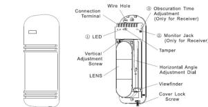
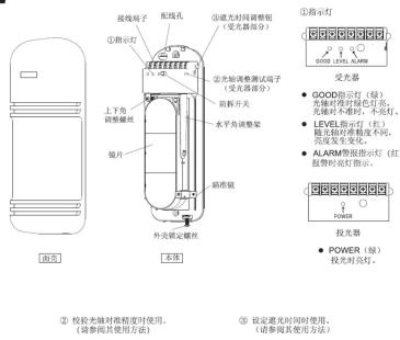
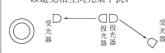
PARTS DESCRIPTION
text_image
Connection Terminal Wire Hole ① LED Vertical Adjustment Screw LENS ② Obscuration Time Adjustment (Only for Receiver) ③ Monitor Jack (Only for Receiver) Tamper Horizontal Angle Adjustment Dial Viewfinder Cover Lock ScrewCOVER
① LED
-
RECEIVER
ND (Green)
:On when optically aligned :Off when optically not align
LEVEL (Red)
:Intensity varies with signal
:Alarm indication lamp
② Monitor jack. Should be used for making the optimum optical axis adjustment (Refer to 'how to use the monitor jack')
③ Obscuration time adjustment: To be used for setting the obscuration time
(Refer to Adjustment of Observation time)

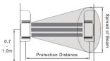
SUGGESTIONS FOR INSTALLATION 2
- Note that here the protection distances refers to the sheet below.
| Model | Protection Distance | Spread of Beam |
| DS-PI-T50 | 50m | 1.5m |
| DS-PI-T100 | 100m | 3m |
| DS-PI-T150 | 150m | 4.5m |
| DS-PI-T200 | 200m | 6.5m |
| DS-PI-T250 | 250m | 9.75m |
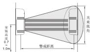
• Height of installation and protection distance
1. 2017年1月1日至2018年1月1日(含)的公司股票交易均价为4.56元/股,与前一交易日收盘价相比,涨幅为-0.97%。
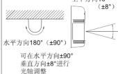
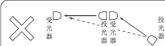
• Direction of installation
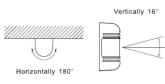
Because angle of reflection mirror is adjustable in ±90^ horizontally and ±8^ vertically, the unit can be installed in various directions.
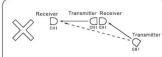
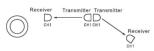
In case of jump phenomenon, as shown ☒ section in the above, change the disposition of transmitter and receiver to the following manner shown ☐ section.

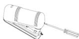
INSTALLATION
- WALL MOUNT
1 Loosen screw holding cover and
remove the cover.
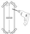
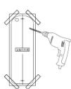
- Attach the mounting pattern
paper to the wall, mark the installation holes, and make
guide holes.
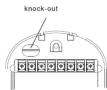
- Break knock-out and pull wire through
through.
[Non-Text]
-
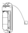
Attach the unit to the wall.
-
Connect wires to the terminal
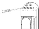
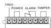
TERMINAL CONFIGURATION
FREE
POWER FREE TAMPER
(2) 12 (3) 12 (4) 12 (5) 12 (6) 12 (7) 12
d
TRANSMITTER
TRANSMITTER
- Wiring distance
Model Wire diameter Voltage DS-PI-T50 DS-PI-T100 DS-PI-T150 DS-PI-T200 DS-PI-T250 12V 24V 12V 24V 12V 24V 12V 24V 12V 24V 0.3mm (p 0.6) 268m 2411m 214m 1929m 179m 1607m 130m 1250m 86m 850m 0.5mm (p 0.8) 469m 4219m 375m 3375m 313m 2813m 245m 2250m 180m 1620m 0.75mm (p 1.0) 625m 5625m 500m 4500m 417m 3750m 310m 2550m 225m 2010m 1.25mm (p 1.2) 938m 8438m 750m 6750m 625m 5625m 475m 4150m 320m 2650m

RECEIVER
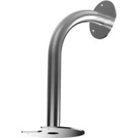
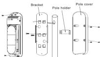
- POLE MOUNT
- Pull the wire through the wire hole of the pole.
where there of the pole.

- Attach the bracket to the pole with the pole holder.
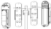
- Pole mount back-to-back
Each bracket to be reversely attached

ADJUSTMENT OF OPTICAL AXIS
- It is important to ensure correct optical alignment between the transmitter and receiver for proper operation.
- Turn on the power supply after uninstallation. Place the viewfinder on either right or left hand side of the lens whichever makes easier viewing.
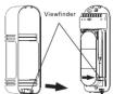
- Look through the viewfinder as shown below.

- Adjust the angle of the lens via the Horizontal angle adjustment and the Vertical adjustment screw so that the sensor can be seen in the center of the Viewfinder. This adjustment is carried out on both the Transmitter and Receiver. Confirm after adjustment that the green GOOD LED is on, otherwise alignment should be readjusted. The red LEVEL LED lamp will be brighter dependent on higher signal levels.
NOTE: After completion of optical adjustment, ensure that both filters on the receiver are replaced to their original position behind the mirrors.
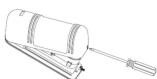
- HOW TO USE THE MONITOR JACK
The best adjustment of optical axis can be done by reading the output voltage of the monitor jack.
Monitor Jack
- insert the meter pins into the monitor jack.
(Pay attention to the polarity because of DC voltage)
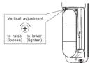
- a) Adjust the horizontal adjustment until the output is at a maximum. b) Adjust the vertical adjustment screw to obtain best signal.
(Do not interrupt beam by hands during the adjustment)
- The following minimum voltages should be obtained to ensure best performance
2.3V for all of the series. If receiver should be re-aligned.
NOTE: If the sensors are too close together then the signal level saturates and the iR beam may be shut-down. This is normal and will only be achieved during bench testing. Signal levels are restored under normal operation distances.

ADJUSTMENT OF OBSCURATION
Set the obscuration time of the receiver by adjusting the obscuration time control to the required setting according to the sketch beside. The obscuration time should be set lower to detect faster moving targets, however care should be taken to note the environmental conditions as the obscuration time should be set higher to ignore conditions where there are a lot of birds or wind blown material.
(1) 本说明仅供参考。

Obscuration time control

fast running at

walking with qu

normal walking

slow action

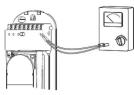
CONFIRMATION OF OPERATION
After completion of the installation, confirm correct operation by suitable walk test. Refer to the following LED indications during the walk test. Confirm tamper operation prior to replacing covers. Confirm system operation with covers replaced.

TROUBLE SHOOTING GUIDE
| Q Symptom | Possible cause | A Remedy |
| Indication lamp of Transmitter does not light. | Improper voltage of power supply | Check power supply and wiring |
| Power supply indication Lamp of Receiver does not light | Improper voltage of power supply | Check power supply and wiring |
| Alarm indication lamp does not light even when the beams are intercepted | 1 Infrared beam from Transmitter is replaced by the receiver, object and sent into the Receiver.2 Three beams are not intercepted at the time.3 Shorter obscuration time than that set up the obscuration time.4 Shorter obscuration time setting to be shorter. | 1 Remove the reflecting object or change in the position for installation and the optical axis direction2 Check three beams to intercept at the time.3 Adjust obscuration time setting to be longer. |
| Although alarm LED lights the beams are intercepted, alarm does not ring. | 1 Broken wires or short on the signal wires.2 Match bridge on the signal connection (Wrong current on the signal wires) | 1 Check the wiring.2 It needs to be repaired. |
| Alarm LED on the Receiver does not turn off. | 1 Inadequate optical axis, which is between the Transmitter and the Receiver.2 Dirty cover or dirty reflection on mirror of the Transmitter and/or Receiver. | 1 Readjust the optical axis.2 Remove the shading objects.3 Clean optics with soft cloth. |
| Intermittent alarm. | 1 Bad wiring connection.2 Change of supply voltage.3 Shading objects moving by wind between the transmitter and the Receiver.4 Unstable installation of the sensor unit.5 Incomplete optical axis adjustment.6 Reddy and other large flying objects intersect the beam | 1 Check the wiring connection.2 Check the voltage (for stabilized supply voltage.)3 Remove the shading objects or change the plane for installation.4 Fix steady.5 Readjust the optical axis.6 Readjust the obscuration time to be longer or reposition. |
NOTE: Conduct a Walk Test at least once a year

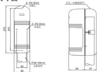
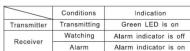
OUTLINE DIMENSION
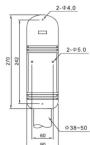
Dimension Unit: mm

SPECIFICATION
| Model | DS-PI-T150 | DS-PI-T100 | DS-PI-T150 | DS-PI-T200 | DS-PI-T250 |
| Alarm Distance | 50m | 100m | 150m | 200m | 250m |
| Max reaching distance | 500m | 1000m | 1500m | 2000m | 2500m |
| Beams NO. | 3 beams | ||||
| Detecting Way | 3 beams Intercepted simultaneously | ||||
| Light Source | Pulse IR LED | ||||
| Response Time | 35~70ms | ||||
| Alarm Output | Relay FORM (C/ONC chargeable), Contact ratings DC 30V 0.5 max, | ||||
| Supply Voltage | DC10.5-28V/(non-polarity) | ||||
| Recommend supply Voltage | DC 12V or 24V/(non-polarity) | ||||
| Supply Current | 70mA | 90mA | 95mA | 100mA | 105mA |
| Operation Temperature Range | -25°C+55°C | ||||
| Tamper Output | Contact Output 1b DC 30V 0.05A max | ||||
| Optic axis adjust angle (Horizontal) | 180°(p80°) | ||||
| Optic axis adjust angle (Vertical) | (°C) (°B) | ||||
| Slight | Removable type | ||||
| Strategy to dew/frost | Ultrasonic structure | ||||
| Other additional functions | Receiving light Indicate. OK Indicate. Testing Terminal | ||||
| Material | PC front cover; ABS Back Cover | ||||
| Environmental humidity | +95%RH | ||||
| Dimensions (H×W×D) | 270mm×90mm×90mm | ||||
| Weight | Around 1100g (Transmitter and Receiver ) | ||||
Model Wire diameter Voltage DS-PI-T50 DS-PI-T100 DS-PI-T150 DS-PI-T200 DS-PI-T250 12V 24V 12V 24V 12V 24V 12V 24V 12V 24V 0.3mm (p 0.6) 268m 2411m 214m 1929m 179m 1607m 130m 1250m 86m 850m 0.5mm (p 0.8) 469m 4219m 375m 3375m 313m 2813m 245m 2250m 180m 1620m 0.75mm (p 1.0) 625m 5625m 500m 4500m 417m 3750m 310m 2550m 225m 2010m 1.25mm (p 1.2) 938m 8438m 750m 6750m 625m 5625m 475m 4150m 320m 2650m
RECEIVER
Model Wire diameter Voltage DS-PI-T50 DS-PI-T100 DS-PI-T150 DS-PI-T200 DS-PI-T250 12V 24V 12V 24V 12V 24V 12V 24V 12V 24V 0.3mm (p 0.6) 268m 2411m 214m 1929m 179m 1607m 130m 1250m 86m 850m 0.5mm (p 0.8) 469m 4219m 375m 3375m 313m 2813m 245m 2250m 180m 1620m 0.75mm (p 1.0) 625m 5625m 500m 4500m 417m 3750m 310m 2550m 225m 2010m 1.25mm (p 1.2) 938m 8438m 750m 6750m 625m 5625m 475m 4150m 320m 2650m


三光束主动红外对射
使用说明书
DS-PI-T50
DS-PI-T100
DS-PI-T150
DS-PI-T250
F© C€

安装上的注意事项1
- 请避免在以下场合设置本探测器


确保在探测器的视线上没有任何误报源,例如灌木丛、树木等。(注意这些物体可能随季节而改变)
确保在探测器被安装在一个稳定和坚固的安装物上面。
确保强力阳光或者汽车的车灯不直接照射到受光器上。(不建议在离光轴±2°内)
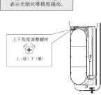
部件名称—光轴调整
1
②校验光轴对准精度时使用。(请参阅其使用方法)
③ 设定遮光时间时使用。(请参阅其使用方法)

安装上的注意事项2
- 安装高度及警戒距离
| 型号 | 警戒距离 | 光束张角 |
| DS-PI-T50 | 50m | 1.5m |
| DS-PI-T100 | 100m | 3m |
| DS-PI-T150 | 150m | 4.5m |
| DS-PI-T200 | 200m | 6.5m |
| DS-PI-T250 | 250m | 9.75m |
- 光轴调整范围
长距离警戒时可使用多组探
测器,请按下图方式安装,以避免相互间光束干扰。

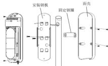
安装方法
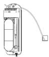
- 拆下固定螺丝取下面壳。
2.将附带的安装对位图粘在墙上,按其孔位打孔。
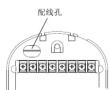
3.将电缆穿过配线孔进行配线。
-
将本体固定在墙上。
-
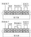
将电缆接入配线端子。
- 配线距离
| 机种\线柱\电压 | DS-PI-T50 | DS-PI-T100 | DS-PI-T150 | DS-PI-T200 | DS-PI-T250 | |||||
| 12V | 24V | 12V | 24V | 12V | 24V | 12V | 24V | 12V | 24V | |
| 0.3mm (g 0.6) | 268m | 2411m | 214m | 1929m | 179m | 1607m | 130m | 1250m | 86m | 850m |
| 0.5mm (g 0.8) | 469m | 4219m | 375m | 3375m | 313m | 2813m | 245m | 2250m | 180m | 1620m |
| 0.75mm (g 1.0) | 625m | 5625m | 500m | 4500m | 417m | 3750m | 310m | 2550m | 225m | 2010m |
| 1.25mm (g 1.2) | 938m | 8438m | 750m | 6750m | 625m | 5625m | 475m | 4150m | 320m | 2650m |
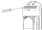
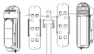
- 固定安装方式
- 在支架上开好引线孔,


↑
- 取下面壳。 3. 将基板固定在支架上。
- 背对背安装时参考下图

-
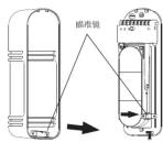
取下面壳后输入电源。
-
将瞄准镜取下,并照图装配。
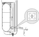
3.距离瞄准镜10cm左右,在右边观察瞄准效果
- 调整上下角调整螺丝及水平调整架,
使对面的探测器影像落入雁雀板中间位置。此时受光器的GOOD指示灯座点
亮。(指示灯不亮时请继续调整光轴)
红色LEVEL指示灯越亮,
-
最佳之光轴调整方法—量度测试孔之输出
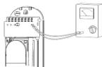
-
将测试笔插入测试孔位(注意“+”,“=”极性)
作垂直调整,方法与水平角度相同
- 如果 2.3V 或以上的电压不能获得,则投光器及
受光器要再作调整

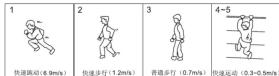
遮光时间的调整
通过旁边的草图得到要求的设置值,调节“遮光时间的调整”来设置受光器的遮光时间。遮光时间必须设置成较小值以便检测较快的移动目标。然而应该考虑各种环境情况,比如当有鸟或者被风吹动的物体时,遮光时间应该设置为较大值来忽略这些情况。

遮光时间的调整

动作确认
在完成安装后,通过恰当的步行测试来确认运行正常。在步行测试时参考下列指示灯。安装面罩前确认防拆功能运作正常。盖面罩后确认系统运作正常。
| 状态 | 表示 | |
| 投光器 | 投光时 | POWER指示灯亮 |
| 受光器 | 警戒时 | GOOD和LEVEL指示灯亮 |
| 警报时 | ALARM警报指示灯亮 |
注意:步行测试至少每年进行一次

异常时的检查
| 故障现象 可能原因 梅修对策 | ||
| 投光器指示灯不亮 | 电源电压大小差 查看电源和线性 | |
| 受光器指示灯不亮 | 电源电压大小差 查看电源和线性 | |
| 无线链断测时是否指示灯不亮 | 1 来自下负荷的红外光束被另一个物体反射进入光束者 2 三个负载没有时间被断断 逆跳时间小于个超载控制设预定的时间 | 1 移开短射物体或者改变安位位置和光轴方向 2 检注一个光束被同时遮断, 6 将遮断时间设置逻辑到较低值 |
| 无线链断测时虽然有 | 1 信号线浮通或者接地 2 信号线指示灯间隔 (信号线上有不正常的电流) | 1 检查线连接 2 漂直波接收 |
| 报警警示不响 | 1 车轴调整不当者 2 投光器和光束者无制除掉物。 2 投光器和光束者的外罩或者反射镜上有污物 | 1 重新调整至轨 2 排异障碍物 3 用具有清洁光学部分 |
| 在受光器上的报警灯常亮不熄灭 | ||
| 断断续段连接 | 1 不良配线连接 2 供电电压变化 3 投光器和光束器有被风功的障碍物 4 安装与稳固 5 未完全改变故障感 6 当或者其它下的灯饰速断走水 | 1 检查系统连接 2 检查供电电压上的稳定性电压 3 排异障碍物或改变安装位置 4 安装牢固 5 重新调整至轨 6 重新调整跳断时间,把时间调出或刷新设置 |

技术参数
| 型号 | DS-PI-T50 | DS-PI-T100 | DS-PI-T150 | DS-PI-T200 | DS-PI-T250 |
| 繁荣的路 | 50m | 100nm | 150m 200n | h | 250n |
| 最大到达距离 | 500nm 100m | 1500nm 200nm | 2500nm | ||
| 光束数 | 3座 | ||||
| 探测方式 | 无光束同时遮掩地址 | ||||
| 光圈 | 脉冲灯外光束 | ||||
| 感应强度 | 35~700mA | ||||
| 装置输出 | 换电节点可输出1C,接点容量DC 30V 0.5Amax. | ||||
| 电源电压 | DC10.5~28V(无极性) | ||||
| 推荐工作电压 | DC 12V或者24V(无极性) | ||||
| 消耗电流DC 12V) | 70mA 90mA 95mA | 100mA 10mA | |||
| 启用温度范围 | -25°C~+55°C | ||||
| 因拆除出 | 接点输出至DC 30V 0.05A max | ||||
| 光脑调整角度(水平) | 180°(+90°) | ||||
| 光脑调整角度(垂直) | 16°(+8°) | ||||
| 振荡器 | 可拆置式 | ||||
| 经露、照封地 | 超声波里程 | ||||
| 其他附加功能 | 受光指示、OK指示、测试端子 | ||||
| 材质 | 面罩PCB材质:底壳AB3树脂 | ||||
| 环境湿度 <95%RH | 270mm×90mm×90mm | ||||
| 外形尺寸 | 重量约1100g(受光罩-投光罩) | ||||

外形尺寸图