DSPIT200 - Détecteur de présence Hikvision - Notice d'utilisation et mode d'emploi gratuit
Retrouvez gratuitement la notice de l'appareil DSPIT200 Hikvision au format PDF.
| Caractéristiques Techniques | Non spécifiées |
|---|---|
| Utilisation | Non spécifiée |
| Maintenance et Réparation | Non spécifiée |
| Sécurité | Non spécifiée |
| Informations Générales | Non spécifiées |
FOIRE AUX QUESTIONS - DSPIT200 Hikvision
Questions des utilisateurs sur DSPIT200 Hikvision
0 question sur cet appareil. Repondez a celles que vous connaissez ou posez la votre.
Poser une nouvelle question sur cet appareil
Téléchargez la notice de votre Détecteur de présence au format PDF gratuitement ! Retrouvez votre notice DSPIT200 - Hikvision et reprennez votre appareil électronique en main. Sur cette page sont publiés tous les documents nécessaires à l'utilisation de votre appareil DSPIT200 de la marque Hikvision.
MODE D'EMPLOI DSPIT200 Hikvision
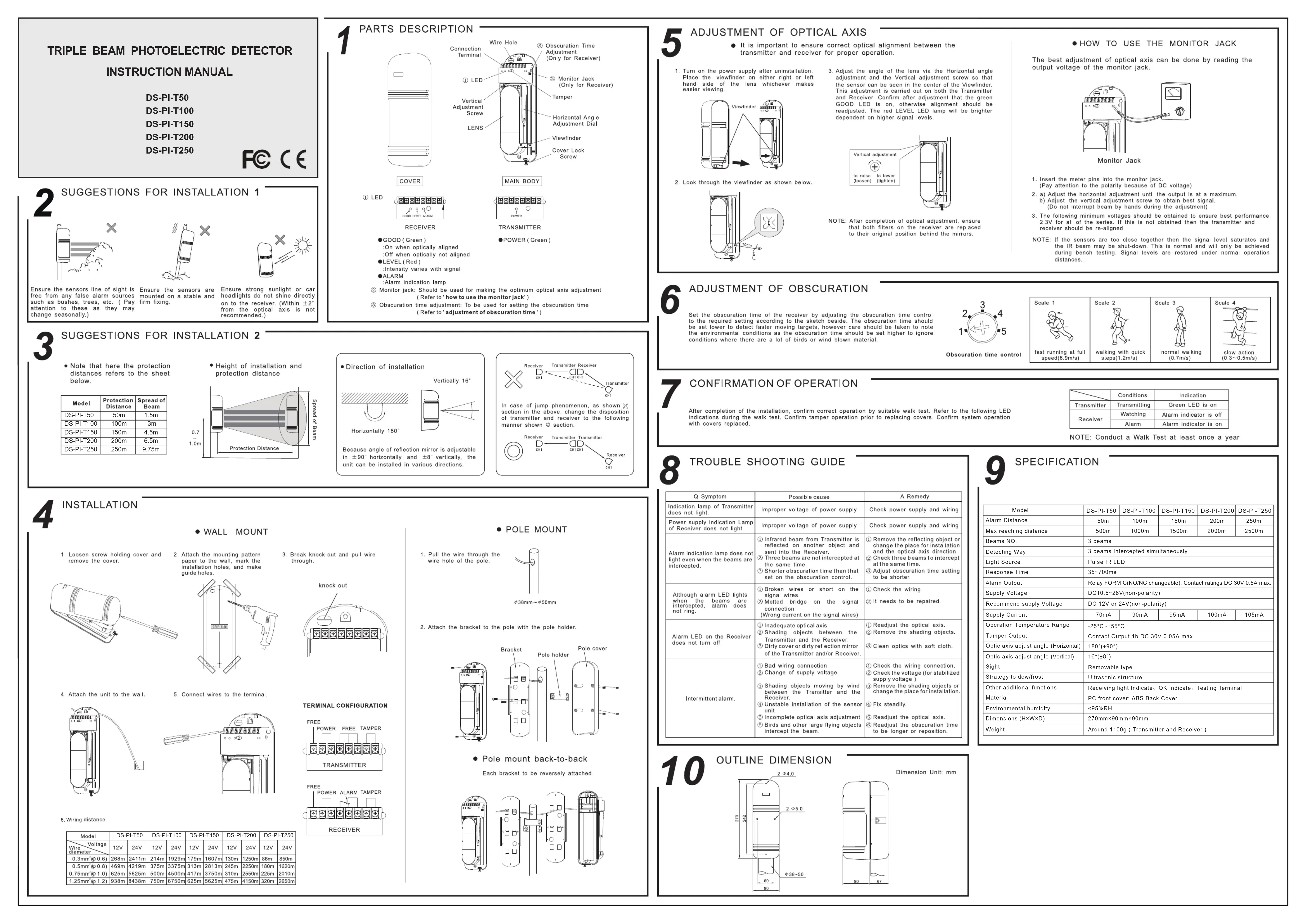
TRIPLE BEAM PHOTOELECTRIC DETECTOR
INSTRUCTION MANUAL
DS-PI-T50
DS-PI-T100
DS-PI-T150
DS-PI-T200
DS-PI-T250
FC C E
PARTS DESCRIPTION
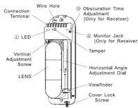
COVER
中
0005 LEVEL:AMM P#E#ED/LEVEL:AMM
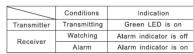
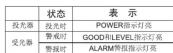
RECEIVER
GOOD (Green) On when optically aligned
Off when optically not align
LEVEL (Red) intensity varies with region
ALARM
Alarm indication lamp Monitor jack Should be
(Refer to 'how to use the m
Obscuration time adjustment: To be used for setting the obscuration time
Refer to adjustment of obscuratlon time
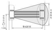
SUGGESTIONS FOR INSTALLATION 2
Note that here the protection
distances refers to the sheet
3
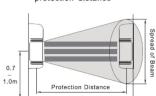
Height of installation and protection distance

-Direction of installation
Because angle of reflection mirror is adjustable, the angle of reflection mirror unit can be installed in various directions.

AD = AC = 1
In case of jump phenomenon, as shown
section in the above, change the disposition of transmitter and receiver to the following
manner shown O section.
Receiver Transmitter Transmitter
中
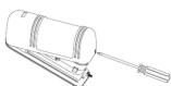
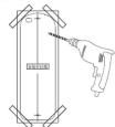
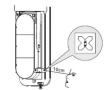
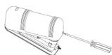
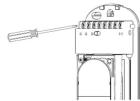
4 INSTALLATION
1 Loosen screw holding cover and
remove the cover.
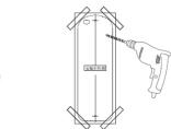
WALL MOUNT
- Break knock-out and pull wire
through.
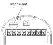
-
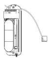
Attach the unit to the wall.
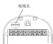
-
Connect wires to the terminal
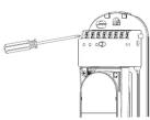
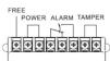
TERMINAL CONFIGURATION
FEE
POWER FREE TAMPER
TRANSMITTER
- Wiring distance
Model: DS-150 DS-PI-100 DS-PI-150 DS-PI-200 DS-PI-250
Vehicle Voltage 12V 34V 12V 24V 12V 24V 12V 24V 12V
Power Voltage 12V 34V 12V 24V 12V 24V 12V 24V 12V
Weight (g) 8.0 (6.8) 49.6 (37.9) 49.6 (37.9) 37.9 (37.9) 37.9 (37.9) 37.9 (37.9) 37.9 (37.9) 37.9 (37.9) 37.9 (37.9) 37.9 (37.9) 37.9 (37.9) 37.9 (37.9)
Weight (g) 8.0 (6.8) 49.6 (37.9) 49.6 (37.9) 37.9 (37.9) 37.9 (37.9) 37.9 (37.9) 37.9 (37.9) 37.9 (37.9) 37.9 (37
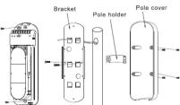
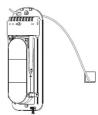
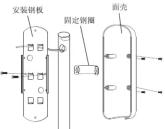
POLE MOUNT
RECEIVER
- Pull the wire through the
wire hole of the pole.

38mm 50mm
- Attach the bracket to the pole with the pole holder
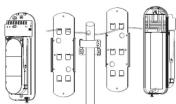
- Pole mount back-to-back
Each bracket to be reversely attached
ADJUSTMENT OF OPTICAL AXIS
It is important to ensure correct optical alignment between the transmitter and receiver for proper operation.
transmitter and receiver for proper operation
1.2
- Pull on the power supply after installation. Place the viewfinder on either right or left
hand side of the lens whichever makes
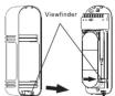
- Look through the viewfinder as shown below.
- Adjust the angle of the lens via the Horizontal Angle Adjustment (H) to achieve the desired angle of the sensor can be seen in the center of the Viewfinder and the vertical axis of the sensor. The H is set to 0, and Receiver Confirm after adjustment that the green light is turned off. The receiver confirm is readjusted. The red LEVEL LED temp will be brighter than the green level.
NOTE: After completion of optical adjustment, ensure that both sides of the camera are aligned.
that both filters on the receiver are replaced to their original position behind the mirrors.
HOW TO USE THE MONITOR JACK
The best adjustment of optical axis can be done by reading the output voltage of the monitor jack.
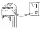
Monitor Jack
- Insert the meter pins into the monitor jack.
(Pay attention to the polarity because of DC voltage)
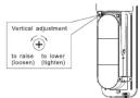
- a) Adjust the nonhorizontal adjustment until the output is at a b) Adjust the vertical adjustment screw to obtain best sign
Do not interrupt beam by hands during the adjustment
- The following minimum voltages should be obtained to ensure best 3.20 for all of the series: If this is not obtained then the transp
1.39 for an of the serial: 1.1 receiver should be re-aligned.
NOTE: If the sensors are too close together then the signal level saturates and
the iR beam may be shut-down. This is normal and will only be achieved during launch testing. Gromil's law does not control the normal operation
during some distances.
ADJUSTMENT OF OBSCURATION
Set the obsecuration time of the receiver by adjusting the obsecuration time control. The obsecuration time is set to 0.5 s for the first time, and it is set to 1 s for the second time. The obsecuration time is set to 2 s for the first time, and it is set to 3 s for the second time. The environmental conditions as the obsecuration time should be set higher to improve the performance of the system.

Obscuration time control
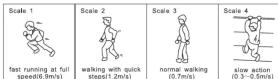
CONFIRMATION OF OPERATION
After completion of the installation, confirm correct operation by suitable walk test. Refer to the following LED circuit during the walk test. Confirm tamper operation prior to replacing covers. Confirm system operation with covers and the installation.
NOTE: Conduct a Walk Test at least once a year
TROUBLE SHOOTING GUIDE
| Q Symptom | Possible cause | A Remedy |
| Indication lamp of Transmitter does not light. | Improper voltage of power supply | Check power supply and wiring |
| Power supply indication Lamp of Receiver does not light. | Improper voltage of power supply | Check power supply and wiring |
| Alarm indication lamp does not light even when the beams are intercepted. | ① Infrared beam from Transmitter is reflected and directed at the object and sent into the Receiver; ② Short or short duration time not intercepted at the same time ③ Shorter obscuration time than that at the receiver; ④ No obscuration during the same time | ① Remove the reflecting object or shade for protection and the optical axis direction ② Remove the objects to intercept at the same time ③ Adjust obscuration time setting to be shorter to the shortest course |
| Although alarm LED lights when the beams and intercepted, alarm does not ring. | ① Broken wires or short on the signal wires ② The beam on the signal connection (reception unit) on the signal wires | ① Check the wiring. ② It needs to be repaired. |
| Alarm LED on the Receiver does not turn off. | ① inadequate optical axis ② Shading objects between the transmitter and the Receiver ③ Dirty cover or dirty reflection mirror of the Transmitter and/or Receiver. | ① Readjust the optical axis. ② Remove the shading objects. ③ Clean optics with soft cloth. |
| Intermittent alarm. | ① Bad wiring connection. ② Change of supply voltage. ③ Shading objects moving by wind or rain, snow, snow, ice and the receiver. ④ Unstable installation of the sensor unit. ⑤ Complete optical axis adjustment ⑥ Binds and other large flying objects intercept the beam | ① Check the wiring connection. ② Check the voltage (or stabilized supply voltage). ③ Remove the shading objects or shade for installation. ④ Fix steadily. ⑤ Readjust the optical axis ⑥ Readjust the obscuration time to be longer or reposition. |
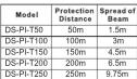
SPECIFICATION
| Model | DS-PL-T150 | DS-PL-T100 | DS-PL-T150 | DS-PL-T7200 | DS-PL-T2300 |
| Alarm Distance | 50m | 100m | 150m | 200m | 250m |
| Max reaching distance | 500m | 1000m | 1500m | 2000m | 2500m |
| Beans NO | 3 beams | ||||
| Detecting Way | 3 beams intercepted simultaneously | ||||
| Light Source | Pulse IR LED | ||||
| Response Time | 35~700ms | ||||
| Alarm Output | Relay FORM (C/NONE changeable), Contact ratings DC 36V 0.5A max. | ||||
| Supply Voltage | DC10.5-28V(non-polarity) | ||||
| Recommend supply Voltage | DC 12V or 24V(non-polarity) | ||||
| Supply Current | 70mA | 90mA | 95mA | 100mA | 105mA |
| Operation Temperature Range | -25°C to +55°C | ||||
| Tampeter Output | Contact Output: 1b DC 30V 0.05A max | ||||
| Optic axis adjust angle (Horizontal) | 80°(±9°) | ||||
| Optic axis adjust angle (Vertical) | 16°(°) | ||||
| Sight | Removable type | ||||
| Strategy to dew/ frost | Ultrasonic structure | ||||
| Other additional functions | Receiving light indicate: OK Indicate - Testing Terminal | ||||
| Material | PC front cover: A/B Back Cover | ||||
| Environmental Humidity | <95%RH | ||||
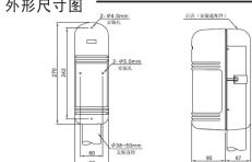
| Dimensions (H+W+D) | 270mm×90mm×90mm | ||||
| Weight | Around 1100g (Transmitter and Receiver ) | ||||
10 OUTLINE DIMENSION
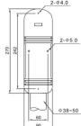
Dimension Unit: mm

三光束主动红外对射
使用说明书
DS-PI-T50
DS-PI-T100
DS-PI-T150
DS-PI-T200
DS-P1-T250
FC C E
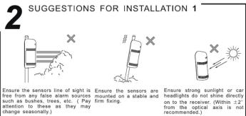
安装上的注意事项1
- 请避免在以下场合设置本探测器

请在调查结束的线段上没有任何“折痕”(如图1-20);
(注:此表格中除更新部分而变更)

确保在探测器被安装在一个稳定和坚固的安装物上面。

确保盈利能力或成为汽车的刹车点不直接损害到竞品者,而要通过创新来赢得消费者。
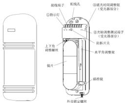
部件名称一光轴调整
曲亮


3 安装上的注意事项2
安装高度及警戒距离
| 型号 | 带宽距离 50m | 光束角 波 |
| DS-P-TL90 | 1.5m | |
| DS-P-TL100 | 100m | |
| DS-P-TL150 | 150m | |
| DS-P-TL200 | 200m | |
| DS-P-TL250 | 250m |
光轴调整范围
(±8°)
水平方向180°(±90°)
可在水平方向±90
垂直方向±8°进行光轴调整


4 安装方法
1.供于固是绿以取下固%。
- 墙壁安装方式
- 将附带的安装对位图粘在墙上,按其孔位打孔。
- 将电缆穿过配线孔进行配线。
4.将本体固定在墙上。
- 将电缆接入配线端子。
预备端子 1.电源,服务端子 端子
投光器
预备端子 电源 警报输出 关断点
受光器
- 固定安装方式
1.在支架上开好引线孔
并引出电缆线。

支票外径:1mm×9mm
2.取下面壳。 3.将基板固定在支架上。
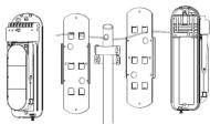
- 背对背安装时参考下图
5
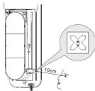
1.取下面壳后输入电源
2.将瞄准镜取下,并照图装配。
3.距离瞄准镜10cm左右,在右边观察瞄准效果
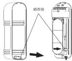
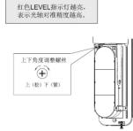
1.调整上下角调整螺丝及水平调整架,
使对面的探测器影像落入瞄准机中并位置。此时受光器的6000指示灯应点
亮。(指示灯不亮时请继续调整光轴)
-最佳之光轴调整方法一量度测试孔之输出
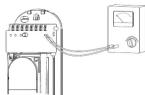
- 将测试笔插入测试孔位(注意“#”、“#”极性);
-
按住鼠标不动,按住鼠标不放,按住鼠标不放。
-
先测量水平角度,直至测试电压输出最大,然后作垂直调整,方法与水平角度相同。
3.如果2.3V或以上的电压不能获得,则投光器及
受光器要再作调整。
6
遮光时间的调整
通过旁边的草图得到要求的设置值,调节“滤光时间的调整”来设置受光器的遮光时间。
遮光时间必须设置成较小值以便检测较快的移动目标。然而应该考虑各种环境情况,比如当有鸟或者被风所动的物体时。遮光时间应该设置为较大值来忽略这些情况。

光时间的调整
7
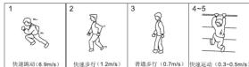
动作确认
在完成安装后,通过恰当的步行测试来确认运行正常。在步行测试时参考下列指示灯
安装面罩前确认防拆功能运作正常。盖面罩后确认系统运作正常
注意:步行测试至少每年进行一次
异常时的检查
| 故障现象可能原因是维修方法 | |
| 投光器指示灯不亮 | 电源电压不合法检查电源和线路 |
| 受光指示灯不亮 | 电源电压不合法检查电源和线路 |
| 光线被遮蔽时蓝闪 照指示灯不亮 | ① 来自于投影罩的红外光束另一物体 反射进入光线。 ② 主要考虑有时间滤波器。 ③ 远视判断不归于投影控制设定的时间 |
| 光线被遮蔽时蓝闪烁 警报指示灯不亮,但 报警声不响 | ① 信号被关闭或者短路 ② 在信号流速有限的持续 (信号线上有不止的电流) |
| 在受光器上的黑光 常亮不熄灭 | ① 光栅调整不当② 在投影器和光源之间有障碍物。 ③ 投影和光源的外罩或者反倾板上 有污迹 |
| 渐渐继续报警 | ① 不可靠或损坏 ② 供电电压变化 ③ 在投影头和光源没有被风吹动的障碍物。 ④ 安装变压器 ⑤ 未完成光阑调整 ⑥ 乌布或者其他灯下行踪者断光束 |
10
9 技术参数
| 型号 | DS-Pi-T50 | DS-Pi-T100 | DS-Pi-T150 | DS-Pi-T200 | DS-Pi-T250 |
| 警戒距离 | 50m | 100m | 150m 200m | 250m | |
| 最大距离距离 | 500m/100m | in 1500m 200m | 2500m | ||
| 光束数 | 3星 | ||||
| 探测方式 | 光电同步监测检校式 | ||||
| 光圈 | 施对冷外光束 | ||||
| 曝光度范围 | 3~700nm | ||||
| 被测输出 | 继电器调节或12位。接单置零DC 30V 0.5Amax。 | ||||
| 电源电压 | DC10.5-28V(无极性) | ||||
| 推荐工作电压 | DC 12V/高/低24V(无极性) | ||||
| 待录电流(DC 12V) | 70mA/90mA | 95mA | 100mA | 105mA | |
| 使用温度范围 | -25°C/+55°C | ||||
| 防抖输出 | 按点输出DC 30V 0.05A max | ||||
| 光轴调整角度(水平) | 180°(±90°) | ||||
| 光轴调整角度(垂直) | 10°(±8°) | ||||
| 可调器 | 可调器式 | ||||
| 进路、载波对准 | 超声波结构 | ||||
| 其他附加功能 | 受光指示、OK指示、测试端子 | ||||
| 材质 | 聚丙烯胶;底壳ABS树脂 | ||||
| 环境温度<95%RH | 270mm×90mm×90mm | ||||
| 外形尺寸 | 270mm×90mm×90mm | ||||
| 重量 | 约1100g(受光反射-投光量) | ||||