
WHTR41200C - Déclencheur à distance HAGER - Notice d'utilisation et mode d'emploi gratuit
Retrouvez gratuitement la notice de l'appareil WHTR41200C HAGER au format PDF.

| Caractéristiques techniques | Déclencheur à distance HAGER WHTR41200C, compatible avec divers systèmes de gestion d'énergie. |
|---|---|
| Utilisation | Permet de contrôler à distance des appareils électriques, idéal pour la domotique et la gestion d'énergie. |
| Maintenance et réparation | Vérifier régulièrement les connexions et l'état des composants. Remplacer les pièces défectueuses selon les recommandations du fabricant. |
| Sécurité | Respecter les normes de sécurité électrique lors de l'installation. Ne pas manipuler sous tension. |
| Informations générales | Produit conçu pour une utilisation intérieure, vérifier la compatibilité avec votre installation électrique avant l'achat. |
FOIRE AUX QUESTIONS - WHTR41200C HAGER
Questions des utilisateurs sur WHTR41200C HAGER
0 question sur cet appareil. Repondez a celles que vous connaissez ou posez la votre.
Poser une nouvelle question sur cet appareil
Téléchargez la notice de votre Déclencheur à distance au format PDF gratuitement ! Retrouvez votre notice WHTR41200C - HAGER et reprennez votre appareil électronique en main. Sur cette page sont publiés tous les documents nécessaires à l'utilisation de votre appareil WHTR41200C de la marque HAGER.
MODE D'EMPLOI WHTR41200C HAGER
Safety instructions
Electrical equipment may only be installed and assembled by a qualified electrician. Always follow the relevant accident prevention regulations of the country.
Failure to comply with these installation instructions may result in damage to the device, fi - ro or other hazards.
When installing and routing cables, always use the same type of cable and standards for SELV electrical circuit.
These instructions are an integral component of the product and must be retained by the end user.
Design and layout of the device
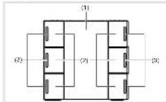
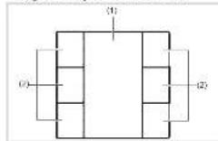
Figure 1: Front view push-button # buttons
Figure 2: Front view camera button 6 clicks with LED and backlighting, with an without IR receiver
(1) Labeling field insert with backlighting
(2) Bullets (number dependent on the variable)
(3) Status LEDs
Function
System information
This device is a product of the KNX system and corresponds to the KNX guidelines. Detailed specialized knowledge obtained from KNX training courses
is required for understanding. The planning, installation and operation of the car can use this help of KNX-smart software.
system link commissioning
The function of the device is software-dependent. The software is to be taken from the product database. You can find the latest version of the product database, technical descriptions as well as conversion and additional support programmes on our website.
easy link commissioning
The function of the device is configuration-dependent. The config generation can also be done using devices developed specially for simple setting and commissioning.
The type of configuration is only possible with devices of the easy link system, easy link stands for easy, visually supported comfallsorbering. Functional configuration is also possible to be in the six outputs by means of a service module:
Correct use
- Operation of loads, e.g. light on/off, dimming,
-
Blind up/down, saving and opening light scenes,
-
Installation into wall box of 45mm depth
- Mounting in trunking
Product characteristics push-button
Commissioning and programming in S-mases and E-mases
- Push-button functions: switchingdlimming,bind control, value transmitter, scene call-up, specifcation of the healing operating mode, priory, allocating switch and converter function
Integrated bus application unit
Lahling field
Additional product characteristics IR push
button with LED Ⅲ Mount f ring plate (f) One status LED per push button position. Note OBSENT
Function and colour of the status LEDs configurable for the device
- Labelling field can be illuminated
Additional product characteristics IR pushbutton with LED
One status LED per pushbutton
Function and outc of the status LEDs configurable for the device
-IR interface with 12 IR channels
- Labelling field can be illuminated
Operation
The functions of the buttons, their operation and the activation of the loads can be adjusted individually for each device.
There are two operating modes:
- Single-surface operation:
Switching lightning on/off or dimming brighter caskers is carried out alternately by repeated pressing of the button.
Two surface operation. Two superposed push-bullons form a function pair. For example, pressing the top surface switches, lighting on makes it brighter, pressing the bottom surface switches it off make it darker.
Operating a function or load
Loads, such as lighting, birds, etc., are operated using the push buttons, which are dependent on the device programming.
The underlying function is executed:
The actuation pulse lasts for the duration of the actuation. Depending on the function, short and long pulses can trigger different actions, e.g. switching or turning.
Function infrared receiver
The infrared devices are B listed with a 12 channel IR receiver. They can be controlled on an operated via a computer, or by the use of a computer control board. The master control allows the same setup of functions as with the conventional local push-ballation functions.
Information for electricians
Installation and electrical connection
DANGER!
Touching live parts in the installation environment can result in an electric shock!
An electric shock can be lethal! Disconnect the connecting cable before working on the device and cover all five parts in the area.
Connecting and installing the device (if figure 3)
Installation into wall box
- Mount a xing plate (ii) to a wall box in the correct position: Note OEBENTOP
ount the device vertically only.
For horizontal mounting the device needs separate accessories (see Accessories).
Press cover plate (5) with front frame (4) onto flinging ring (5) until fastening cleve (3) smeps into piece.
Attach push-button front (2) on the f1ush-mounted insert (3).
Circuit bus connection cable to device (3)
- Open the device (1) into the vehicle plate (2)
1
- Remove device (3):
Disconnect bus line from device (3).
Press cover plate (5) with front frame (4) onto fixing ring (6) until fastening cleav (3) snaps into place.
Attach push-button front [2] on the first mounted insert [3].
Circuit bus connection cable to device (3).
Snap the device (3) into the fixing plate (6).
Dismantling
Remove device (3).
Disconnect bus line from device (3)
Commissioning
system link - Loading the physical address and application software.
The physica address is only ever assigned to the system. The physical device can ever be in programming mode.
If available, release the labeling file instead with bank cover (1) using the programming button
(7)
Switch on bus voltage
Free programing section:
The programming LED light up.
bus voltages is present
Load the physical address into the device.
I. Load application software Note down the above
cal address on the labelling f iid.
The loading of non-compatible application software is indicated by f ashing of the status LEI
(3)
Kazach sampling is a insert with blank cover (1).
easy link
Information on the system conforl generation can be taken from the extensive description of the service and its operation.
Appendix
Technical data
KNX medium TP 1
Gnduction mode system link, easy link
Bated volume KNX 21.32V=5FV
Current consumption KNX 20 mA
Connection mode KNX bus connection terminal
Dimensions(W×H×D) 45×45×17 mm Degree of protection IR-20
Prrnction class
Operating temperature -5 +45C
Storage temperature -20..+70°C
Standards EN 60689-2-1 EN 60689-1 EN 50433
Troubleshooting
Bus operation is not possible.
Gauge Bus voltage is not present.
Check bus connection terminals for correct
Check this volume by briefly pressing the
programming button (7), rad programming LED
lights up if bus voltage is present.
All status LEDs flashing
Cause: The loaded application programme and evaluation metrics are not compatible.
Install new application programme or mount
suitable application module.
Accessories
Bua connecting terminals 1608
Accessories horizontal mounting
Fixing ring electronic process 1N1409825
Exrcf frame WH2028139xZ
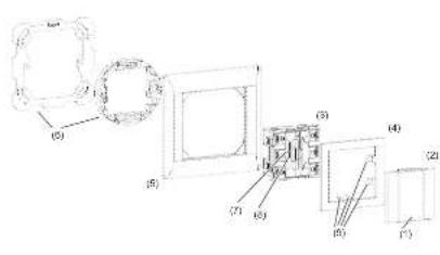
(1) Blank cover and labeling field insert for push-bution and push-bution
with LED (not within scope of delivery). 2) Push button front LED (not within scope
(3)6 buttons KNX-PCU, RGB LED
(4) Cover plate with class (not within scope of delivery)
(5) Frame (not Included)
(6) Fixing plate with attachment ring (not within scope of delivery); (7) Progargaining system
8)ProgrammingLED
(9) Fasting claws
Figure 3. Assembly of the device
Caeer Disp#sion of the Proeet
A
Applicable in the European Union and other European countries with separate collection systems.
To make abstract on the product in the formulae, one must find. The method may be described with the household market of the first type of product. For example, if the household market is a market where the health care system is not controlled, the health care market should allocate copies to this product. This is because the health care market is a market that is economically superior. The reasonable use of such markets remains.
The calculated user's output collected by the user receives their input. They can use the user's input to determine the location of the device, where and how they can take this device for environmentally safe transport.
The mean values of the three parameters are shown in Table 1. The results show that the average value of the mean difference between the two groups is 0.25 .
Usable in all Europe (and in Switzerland).