Cordoba - Armoire Wehkamp - Notice d'utilisation et mode d'emploi gratuit
Retrouvez gratuitement la notice de l'appareil Cordoba Wehkamp au format PDF.
| Type de produit | Armoire |
| Marque | Wehkamp |
| Modèle | Cordoba |
| Dimensions (H × L × P) | 1998 × 1500 × 595 mm |
| Poids approximatif | 65 kg (estimation) |
| Matériau principal | Panneau de fibres de bois à densité moyenne (MDF) ou panneau de particules |
| Finition disponible | Blanc haut brillant, Blanc, Chêne, Miroir + Blanc |
| Nombre de portes | 2 portes (configuration standard) |
| Nombre de tiroirs | Non spécifié (probablement 0-2 selon variante) |
| Étagères incluses | Oui, plusieurs (quantité variable selon modèle) |
| Type de montage | À assembler soi-même (DIY) |
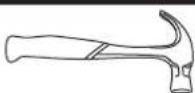
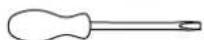
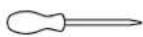
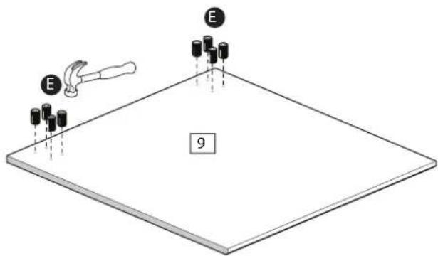
| Outils nécessaires | Tournevis cruciforme, marteau, clé Allen (non fournis) |
| Fixation murale recommandée | Oui, pour la sécurité (antirrenversement) |
| Numéro de modèle de référence | Cordoba 150 (3881006, 3890602, etc.) |
| Entretien et nettoyage | Essuyer avec un chiffon doux légèrement humide. Éviter produits abrasifs. |
| Pays d'origine | Non spécifié (probablement Europe) |
| Garantie | 2 ans (standard Wehkamp) |
FOIRE AUX QUESTIONS - Cordoba Wehkamp
Questions des utilisateurs sur Cordoba Wehkamp
0 question sur cet appareil. Repondez a celles que vous connaissez ou posez la votre.
Poser une nouvelle question sur cet appareil
Téléchargez la notice de votre Armoire au format PDF gratuitement ! Retrouvez votre notice Cordoba - Wehkamp et reprennez votre appareil électronique en main. Sur cette page sont publiés tous les documents nécessaires à l'utilisation de votre appareil Cordoba de la marque Wehkamp.
MODE D'EMPLOI Cordoba Wehkamp
Cordoba 150
text_image
3881006 + 3890602 3881006 + 3890606 3881022 + 3890622 3881006 + 38906806 1500mm 595mm 1998mm 3881006 + 3890602 Hoogglans Wit 3881006 + 3890606 Wit 3881022 + 3890622 Eiken 3881006 + 38906806 Spiegel + Witmontage tekening assembly drawing montagezeichnung croquis montaj resmini
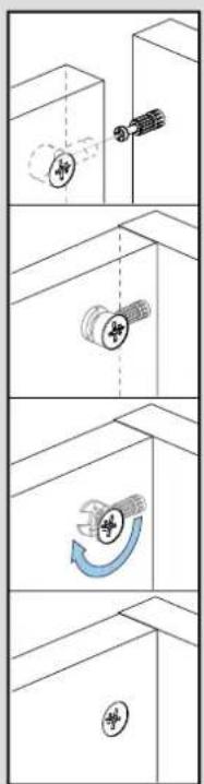
- Bestudeer zorgvuldig de montagetekening voordat u met monteren begint.
- Neem de onderdelen en panelen voorzichtig uit de verpakking en leg ze op volgorde en controleer of alles compleet is.
- Leg het verpakkingsmateriaal ter bescherming onder het te monteren artikel.
- Volg met het monteren exact het stappenplan zoals in de tekening aangegeven.
- Begin met het monteren, wees voorzichtig, forceer niets.
-
Bewaar deze montagetekening zorgvuldig. U heeft deze misschien nodig in het geval u onderdelen wilt aanvragen.
-
Study the assembly drawing carefully before starting the assembly.
- Carefully remove the parts and panels from the packing and place them in sequence. Check to see that nothing is missing.
- For extra protection, place the packing material under the item to be assembled.
- When assembling, follow the step-by-step instructions exactly as given on the drawing.
- Start the assembly. Be careful not to force anything.
-
Take care to save the assembly drawing. It could be needed in case you need to order parts.
-
Studieren Sie die Montagezeichnung gut, bevor Sie mit der Montage beginnen.
- Nehmen Sie die Zubehörteile und Paneelen vorsichtig aus der Verpackung, legen Sie sie in die richtige Reihenfolge und kontrollieren Sie, ob alles komplett ist.
- Legen Sie das Verpackungsmaterial zum Schutz unter den zu montierenden Artikel.
- Folgen Sie bei der Montage genau dem Schritteplan, wie er in der Zeichnung angegeben ist.
- Beginnen Sie mit der Montage, seien Sie vorsichtig, übereilen Sie nichts.
-
Bewahren Sie diese Montagezeichnung gut auf. Sie benötigen diese möglicherweise zur Bestellung von Zubehörteilen.
-
Examinez soigneusement le croquis avant de procéder au montage.
- Sortez soigneusement les pièces et les panneaux de leur emballage, placez-les dans l'ordre et assurez-vous que rien nemanque.
- Placez le matériel d'emballage protecteur sous l'article à monter.
- Suivez scrupuleusement les étapes de montage comme indiqué sur le croquis.
- Commencez le montage. Soyez prudent et ne forcez pas.
-
Conservez soigneusement le croquis de montage. Vous en aurez peut-être besoin lorsque vous souhaiterez remplacer un élément.
-
Montaj i?ine ba?lamadan önce montaj resmini dikkatle inceleyiniz.
- Parçaları ve panoları ambalajından özenle çıkartınız, sıraya koyunuz ve her?eyin tam olup olmadığı?ını kontrol ediniz.
- Monte edilecek nesnenin altına, koruma amacıyla ambalaj malzemesi seriniz.
- Montaj sırasında resimde belirtildi?i gibi safha planını takip ediniz.
- Montaja ba?layınız, dikkatli olunuz ve hiç bir parçayı zorlamayınız.
- Bu montaj resmini iyice saklayınız. ?leride parça ihtiyacı sırasında gerekli olabilir.
text_image
(1) يجب النظر في رسمagraب بندقة قيل الشروع في عمليةagraب. (2) يجبistes الأقصام والألواح من العليا بحذر ووضعها حسب ترتيب كما يجب التأكد من وجود جميع الأقصام. (3) ضع مواد التغليف تحت السلعة المقرير neuro stripes Alberta. (4) يجب متابعة المراحل الموصوفة في رسمagraب خطوة خطة. (5) أبدأ عمليةagraب، يجب القيام بنلك بحذر، لا تربط شينا بشدة حتى لا تخسر شينا. (6) يجب حفظ هذا الرسم. إذا أردت طلب أقصام احتناطية قد تحناجه.Cordoba 150
38810 06
3881022
natural_image
Pure vertical line diagram with evenly spaced dots and endpoints (no text or symbols)
P2883
(199.8 × 52.9cm)
natural_image
Pure vertical line with evenly spaced dots, no text or symbols present
P2882
(199.8×55.8cm)
natural_image
Pure vertical line pattern with evenly spaced dots, no text or symbols present
P2886
(190.3 × 49cm)
natural_image
Simple vertical dashed line with three dots at the top and bottom (no text or symbols)
BO3430 x2
(193 × 74cm)
natural_image
Empty white rectangle with two small black dots at the top and bottom corners (no text or symbols)
P1889
(146.9×51cm)
natural_image
Blank white rectangle with a thin border and two small black dots at the top (no text or symbols)
P1891
(146.9 x 51.1cm)


P7242 x2
(146.9×6cm)
38906 06
38906 22

P1893 x2
(72.7 × 48.8cm)

P3267 x4
(76.5 x 65cm)

P3268 x2
(76.5 × 65.1cm)
38906 02

P1893 x2
(72.7 x 48.8cm)
natural_image
Blank white image with four corner markers (no text or symbols)
FA3266 x2
(195.2×76.5cm)
38906 806

P1893 x2
(72.7 × 48.8cm)

P3267 x2
(76.5 × 65cm)

P3268
(76.5 × 65.1cm)
natural_image
Blank white image with no visible content, text, or symbols
PS3266
(195.2×76.5cm)
Cordoba 150
1/2
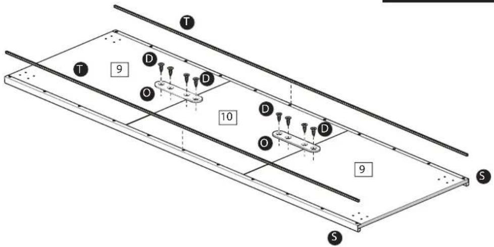
A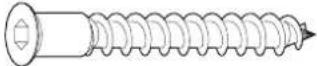 x 4 (5x40mm) x 4 (5x40mm) | FK1005 | B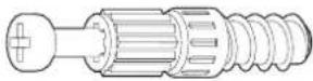 x 18 (5x24mm) x 18 (5x24mm) | FK1011 | C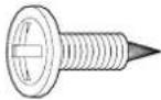 x 77 (4x15mm) x 77 (4x15mm) | FK1400 |
D x 22 (4x12.5mm) x 22 (4x12.5mm) | FK1309 | E x 32 (5x9mm) x 32 (5x9mm) | FK1082 | F x 60 x 60 | FK1515 |
G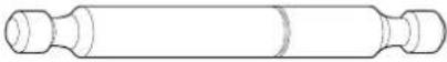 x 3 (5x66.5mm) x 3 (5x66.5mm) | FK1052 | H x 8 (8x30mm) x 8 (8x30mm) | FK1411 | I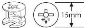 x 24 (15x12mm) x 24 (15x12mm) | FK1012 |
J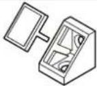 x 2 x 2 | FK1248 | K x 4 x 4 | FK1217 | L x 2 x 2 | FK1234 |
M x 1 x 1 | FK1235 | N x 1 x 1 | FK1419 | O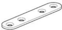 x 4 x 4 | FK1236 |
P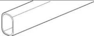 x 2 (719mm) x 2 (719mm) | PM1892 | Q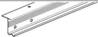 x 1 (1469mm) x 1 (1469mm) | PM1612 | R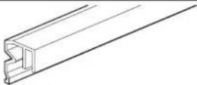 x 1 (1469mm) x 1 (1469mm) | PK1612 |
S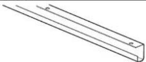 x 3 (1952mm) x 3 (1952mm) | PM1652B | T x 3 (1952mm) x 3 (1952mm) | PM1652C | U x 1 (1952mm) x 1 (1952mm) | PM1652D |
V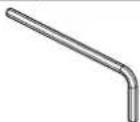 x 1 (3mm) x 1 (3mm) | FK1013 | W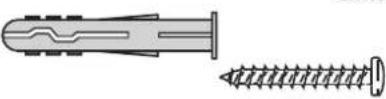 x 1 (6mm) x 1 (6mm) | ZF99936 |
2/2
AA x2 (3.5x35mm) x2 (3.5x35mm) | ZF9997I | AB x11 (3.5x25mm) x11 (3.5x25mm) | ZF9997K | AC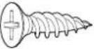 x33 (4x15mm) x33 (4x15mm) | ZF9997L |
AD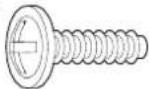 x2 (4x14mm) x2 (4x14mm) | ZF9997J | AE x1 x1 | ZF9997F | AF x2 x2 | ZF9997E |
AG x2 x2 | ZF9997G | AH x2 x2 | ZF9997H | AI x2 x2 | ZF9997C |
AJ x2 x2 | ZF9998D | AK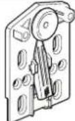 x2 x2 | ZF9997B | AL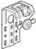 x2 x2 | ZF9997A |
05101520253035404550556065707580859095100
105 110115150125130135140145150155160165170
[Non-Text]
Cordoba 150
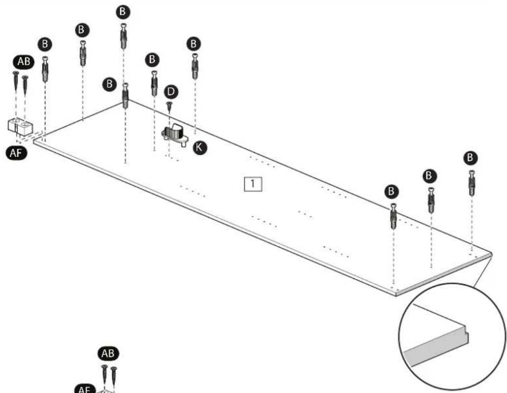
1
2
text_image
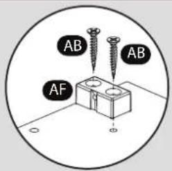
AB AB AF3
text_image
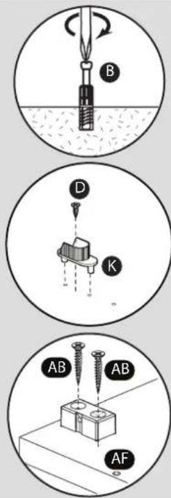
AB B B B B D K AF 1 B B B AB AF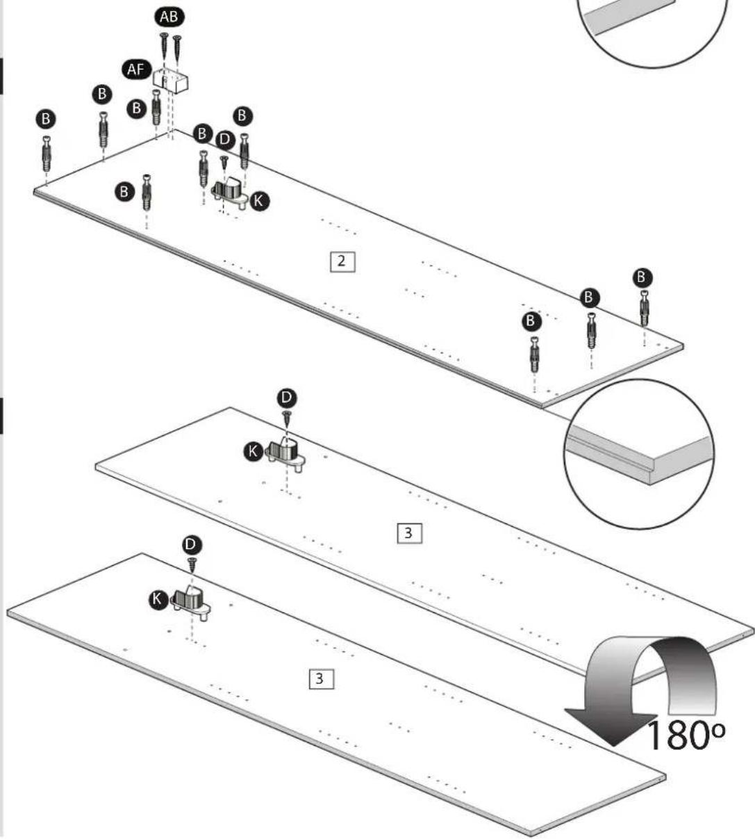
text_image
AB AF B B B B B B 2 B B B D K K D 3 K D 3 180°Cordoba 150
4
natural_image
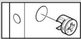
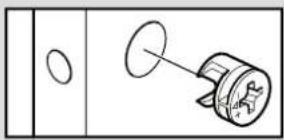
Simple line drawing of a mechanical component with a circular end and a cylindrical shaft (no text or symbols)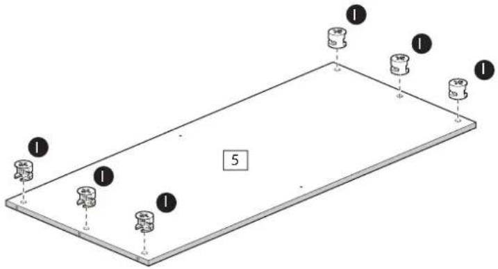
text_image
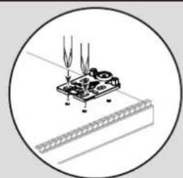
Diagram of a 3D rectangular plate with labeled mechanical components and numbered parts5
natural_image
Simple line drawing of a door handle with a circular opening and a cylindrical component inserted (no text or symbols)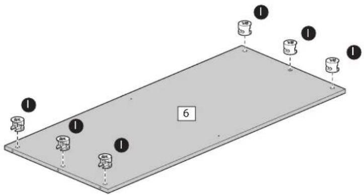
text_image
1 1 1 1 66
natural_image
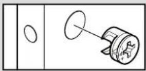
Simple line drawing of a door handle with a circular opening and a mechanical component (no text or symbols)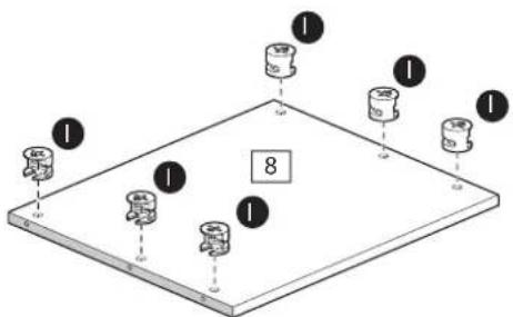
text_image
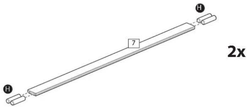
Diagram showing a 3D object with labeled components and numbered parts, likely illustrating a mechanical or electronic assembly.2x
7
text_image
7 H 2xCordoba 150
8
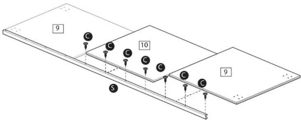
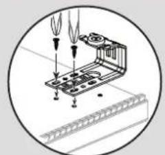
9
flowchart
graph TD
    A["Left Channel"] --> B["Right Channel"]
    B --> C["Bottom Channel"]
    style A fill:#f9f,stroke:#333
    style B fill:#bbf,stroke:#333
    style C fill:#dfd,stroke:#333
10
text_image
Diagram illustrating a mechanical or electrical system with labeled components and directional arrows, likely illustrating a system or process.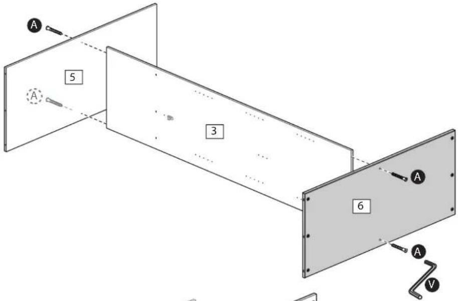
text_image
A 5 A 3 6 A A V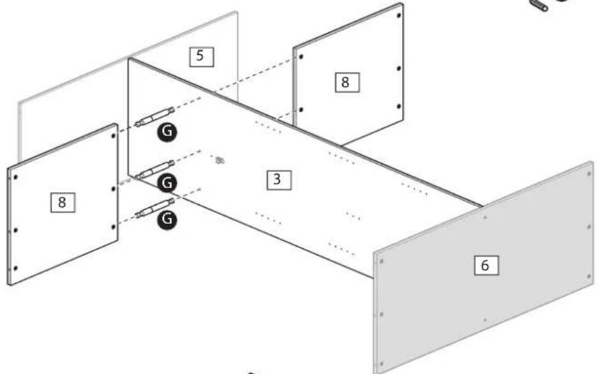
text_image
5 8 3 6 G G G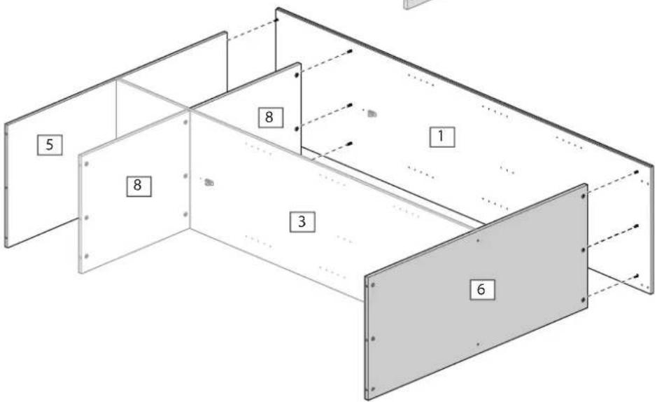
text_image
5 8 8 1 3 611
text_image
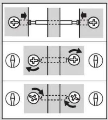
Diagram showing four sequential steps of a mechanical or electrical component assembly, with labeled parts and directional arrows.
text_image
Technical diagram of a modular device with numbered components and an inset showing electrical switch connections.12
text_image
A:A = B:B ±150mm F N
text_image
A B C F 4 2 N B 6 A C F F13
text_image
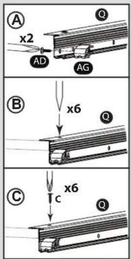
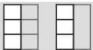
A x2 AD Q AG B x6 Q C x6 Q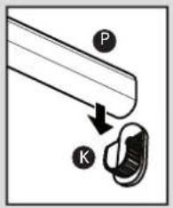
text_image
Diagram showing a mechanical component with labeled parts P and K, indicating a step or assembly.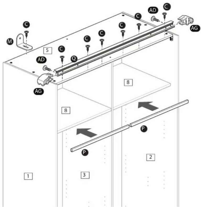
text_image
C M 5 AD Q C C C C AD C AG 8 1 3 2 P P14
text_image
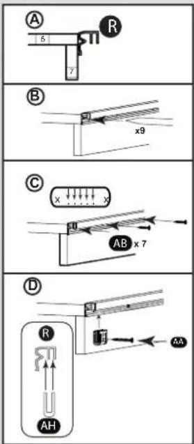
A 5 7 R B x9 C x x AB x 7 D R AH AA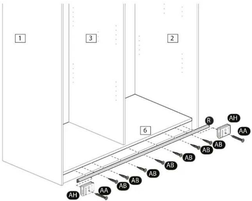
text_image
1 3 2 6 R AH AA AB AB AB AB AB AB AB AH AACordoba 150
15.1
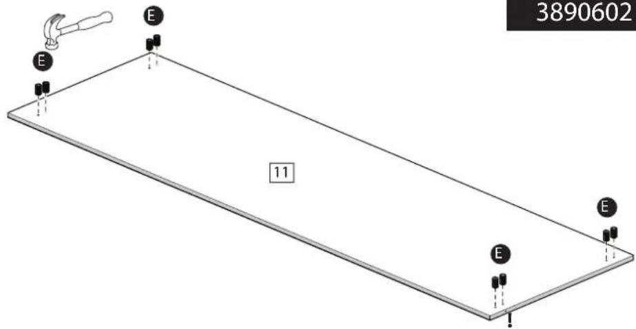
text_image
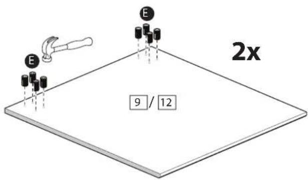
E E 2x 9 / 123890606
3890622
38906806
15.2
text_image
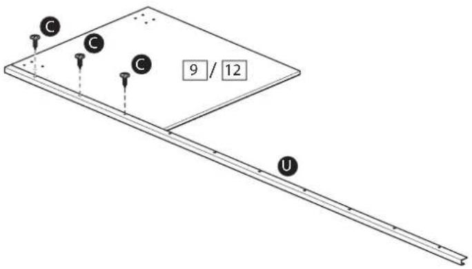
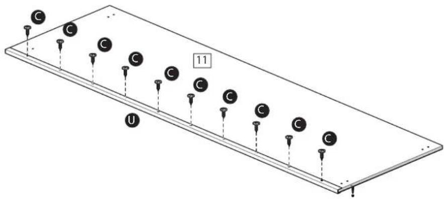
C C C 9 / 12 U15.3
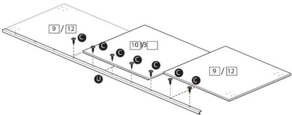
text_image
9 / 12 C C C C C 10 1/3 C C C C U 9 / 1215.4
text_image
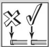
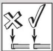
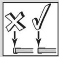
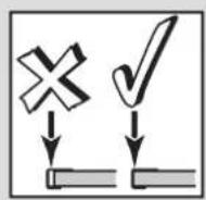
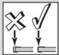
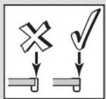
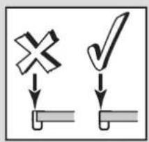
Diagram showing two process steps with a cross and checkmark symbols, likely indicating selection or confirmation.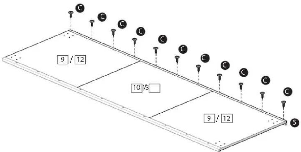
text_image
C C C C C C 9 / 12 10 1/3 9 / 12 S15.5
text_image
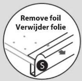
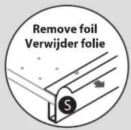
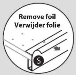
Remove foil Verwijder folie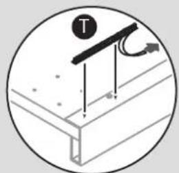
natural_image
Diagram of a mechanical assembly with a tool and directional arrows, no text or symbols present15.6
natural_image
Diagram of an electronic component with wires and a labeled section (no readable text or symbols)
natural_image
Diagram of a mechanical assembly with arrows indicating force or movement (no text or symbols)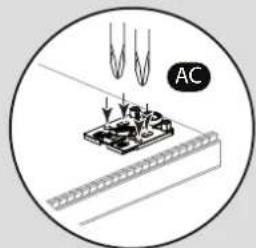
text_image
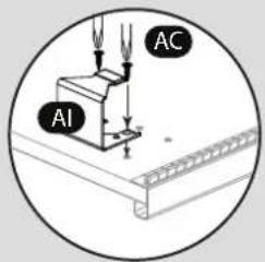
AC15.7
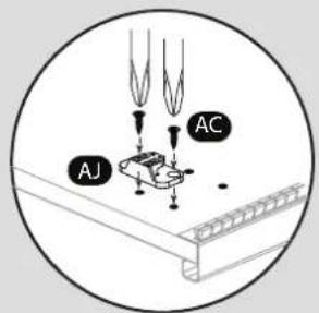
text_image
AJ AC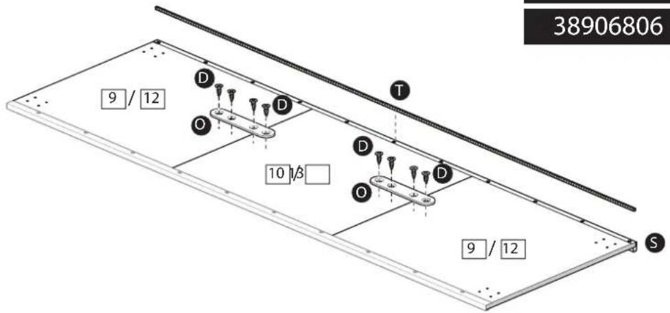
text_image
38906806 9 / 12 D O D 10 1/8 T D O D 9 / 12 S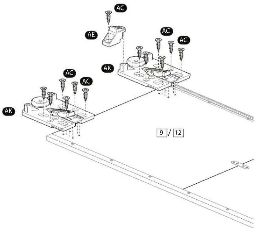
text_image
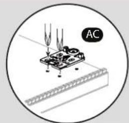
AC AE AC AC AK AK 9 / 12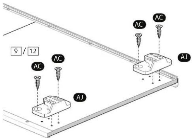
text_image
9 / 12 AC AC AC AJ AJ15.1
3890602
text_image
3890602 E E 11 E E15.2
text_image
C C C C C C C C C C C C U 1115.3

text_image
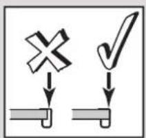
Diagram showing two labeled symbols: a cross and a checkmark, both pointing downward to a surface.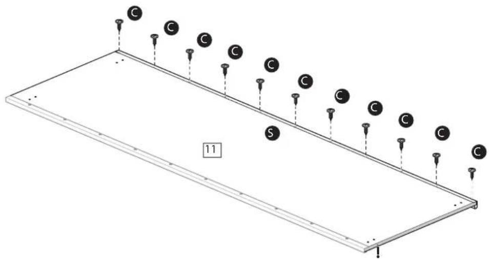
text_image
C C C C C C S 1115.4
3890602
text_image
Remove foil Verwijder folie
natural_image
Diagram showing a mechanical assembly with a rod and force arrow, no text or symbols present15.5
natural_image
Diagram of a microchip mounted on a base with wires extending upward (no text or symbols)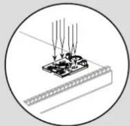
natural_image
Diagram of a mechanical assembly with arrows indicating force or movement (no text or symbols)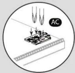
text_image
AC15.6
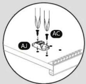
text_image
AJ AC
text_image
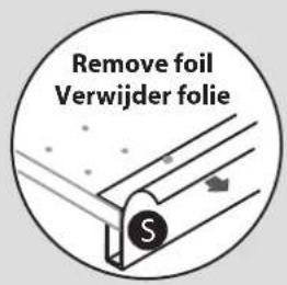
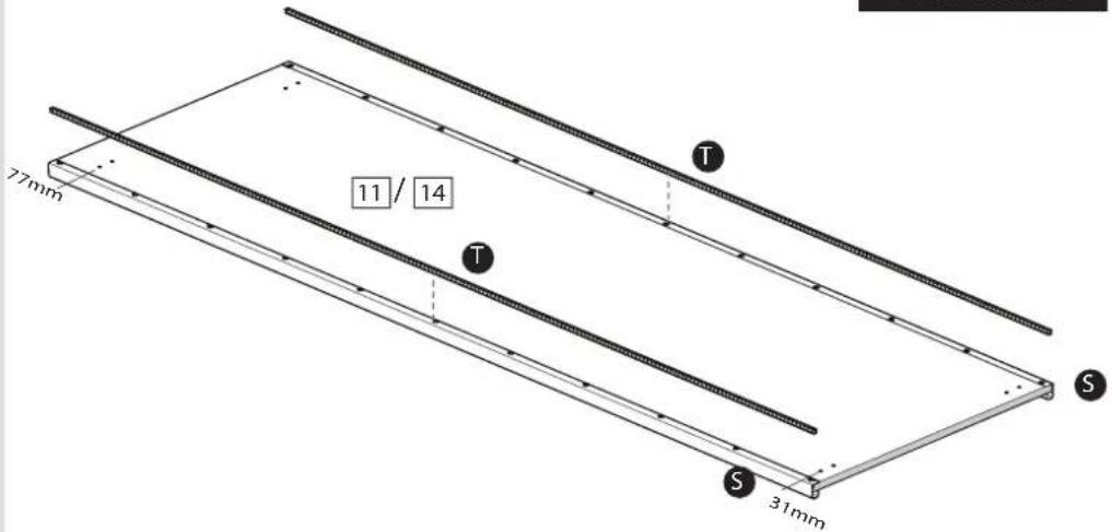
77mm 11 31mm T S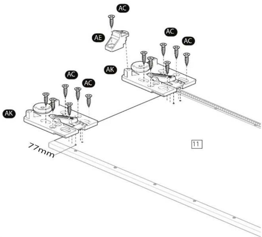
text_image
AC AE AC AK AC AC AK 77mm 11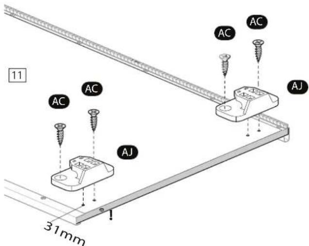
text_image
11 AC AC AC AC AJ 31mm16a
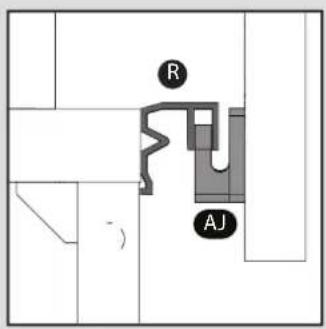
text_image
R AJ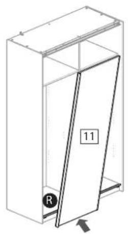
natural_image
Isometric line drawing of a cabinet or enclosure with a door and labeled part (no text or symbols beyond basic labels)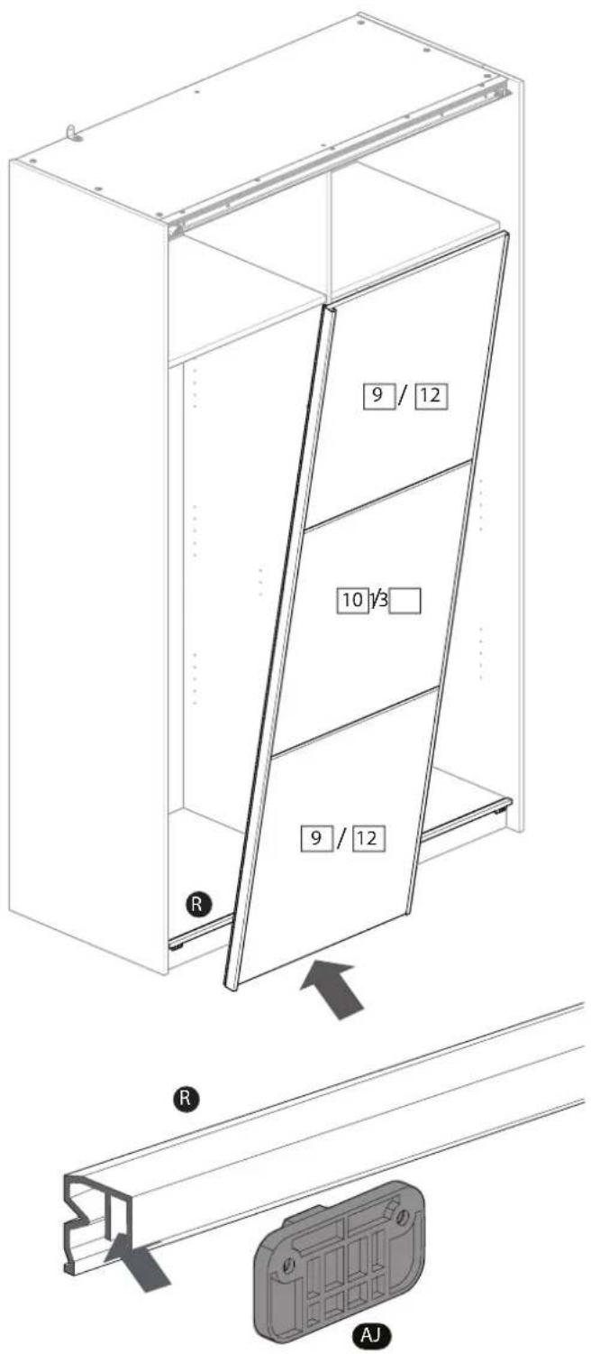
text_image
9 / 12 10 1/3 9 / 12 R R AJ16b
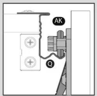
text_image
AK Q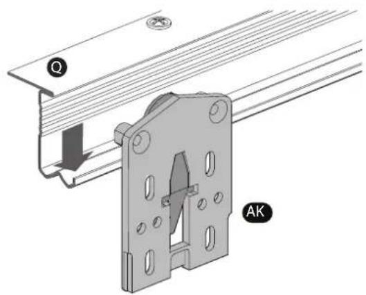
text_image
Technical diagram showing a mechanical assembly with labeled components and directional arrow indicating motion or force.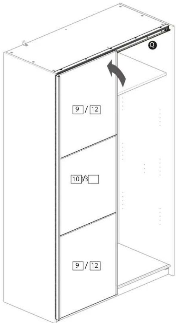
text_image
9 / 12 10 1/3 9 / 12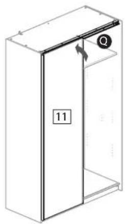
natural_image
Isometric line drawing of a cabinet with labeled door and window (no text or symbols)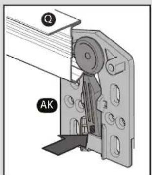
text_image
Q AK17.1
3890606
3890622
17.2
text_image
E E 9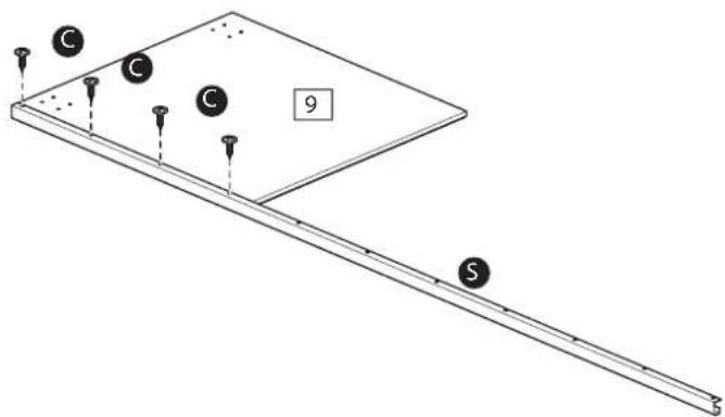
text_image
C C C 9 S17.3
text_image
9 C C C C 10 C C S 917.4
text_image
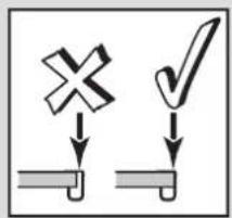
Diagram showing two labeled symbols: a cross and a checkmark, both pointing downward to a textured surface.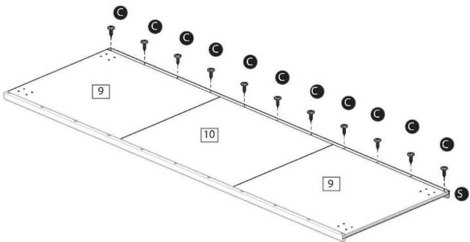
text_image
C C C C C C C C C C 9 10 9 S17.5
text_image
Remove foil Verwijder folie
natural_image
Diagram of a mechanical assembly with labeled component T and directional arrows (no text or symbols beyond basic labels)17.6
natural_image
Diagram of a laboratory setup with test tubes and test tubes being heated by tweezers (no text or labels)
natural_image
Technical line drawing of a mechanical assembly with no visible text or symbols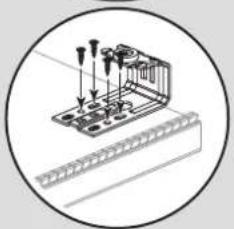
natural_image
Technical illustration of a mechanical assembly with clamps and a ruler, enclosed in a circular frame (no text or symbols)17.7
text_image
AI AC3890606
3890622
text_image
T 9 D O D 10 D O D 9 S S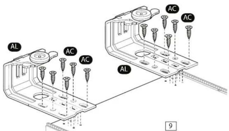
text_image
AL AC AC AL AC AC 9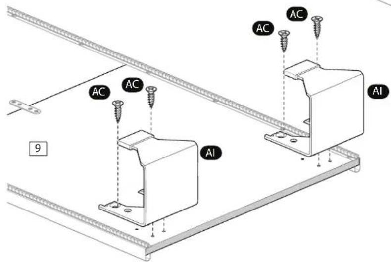
text_image
AC AC AC AC AI 9Cordoba 150
38906806
17.1
17.2
text_image
Diagram showing two labeled symbols: a cross and a checkmark, both pointing downward to a textured surface.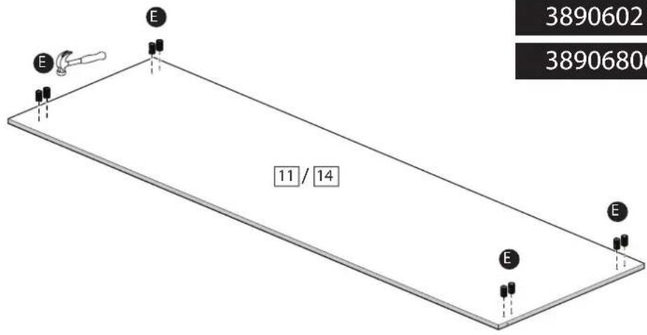
text_image
3890602 3890680 E E 11 / 14 E E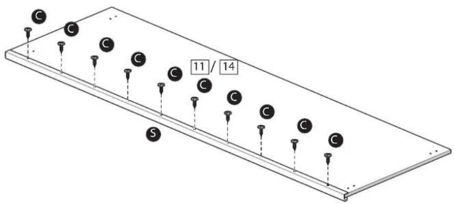
text_image
C C C C C 11 / 14 S17.3
text_image
Diagram showing two labeled symbols: a cross and a checkmark, both pointing downward to a surface.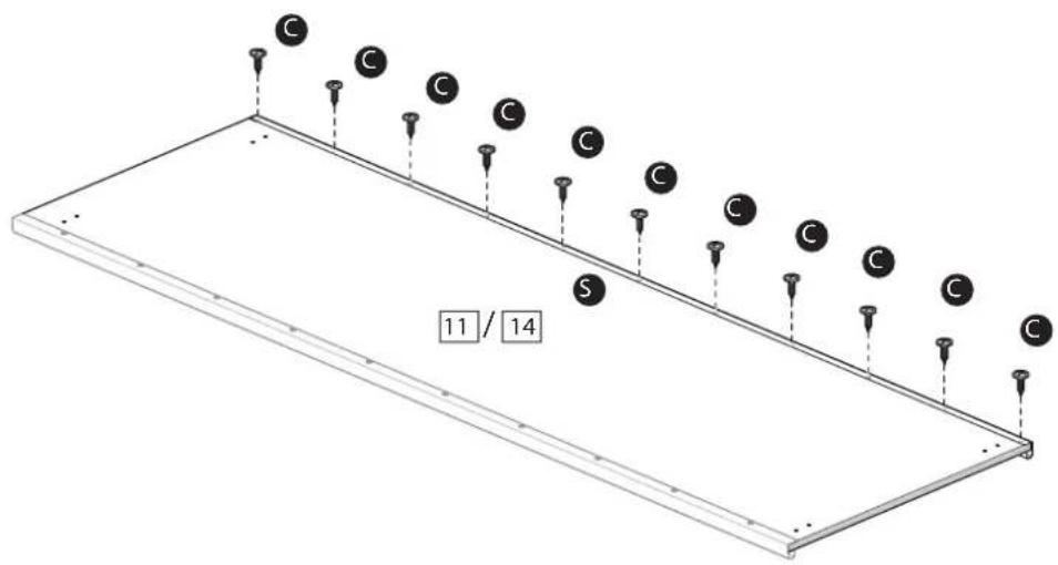
text_image
C C C C C C C C C C C S 11 / 14 C17.4
text_image
Remove foil Verwijder folie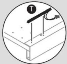
natural_image
Diagram of a mechanical assembly with labeled components and arrows, no readable text or symbols present.3890602
38906806
text_image
77mm 11 / 14 T T S 31mm S17.5
natural_image
Diagram of a laboratory setup with test tubes and a ruler, no visible text or symbols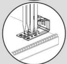
natural_image
Technical line drawing of a mechanical assembly with no visible text or symbols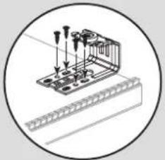
natural_image
Technical illustration of a mechanical assembly with clamps and a ruler, no text or symbols present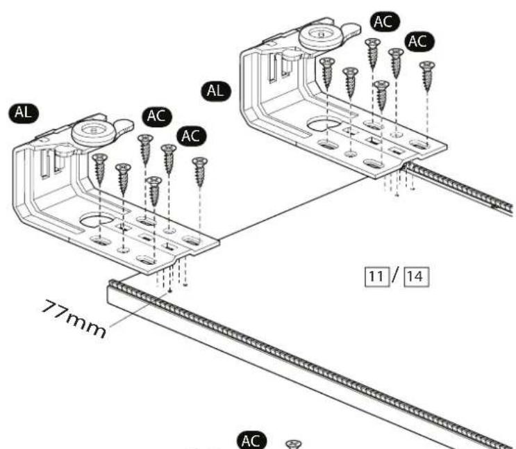
text_image
AL AC AC AL AC AC 11 / 14 77mm AC17.6

text_image
AC AI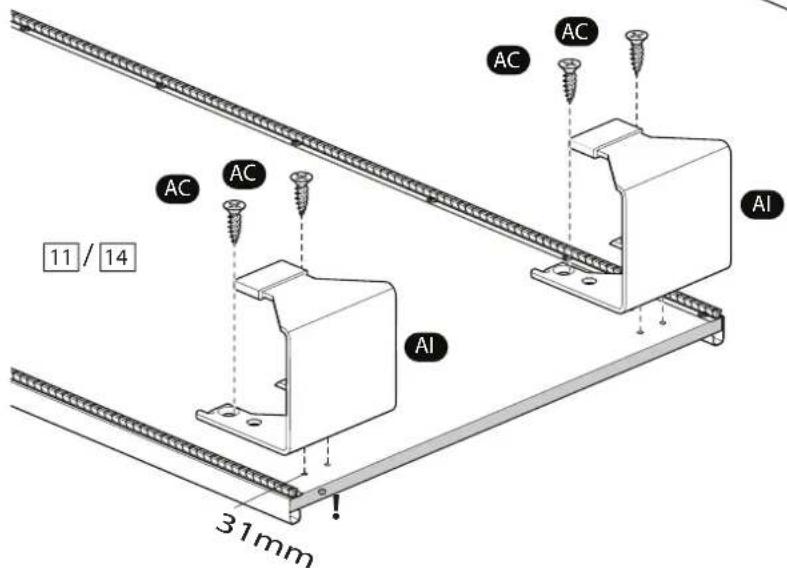
text_image
11 / 14 31mm AC AC AC Al Al18a

text_image
R AI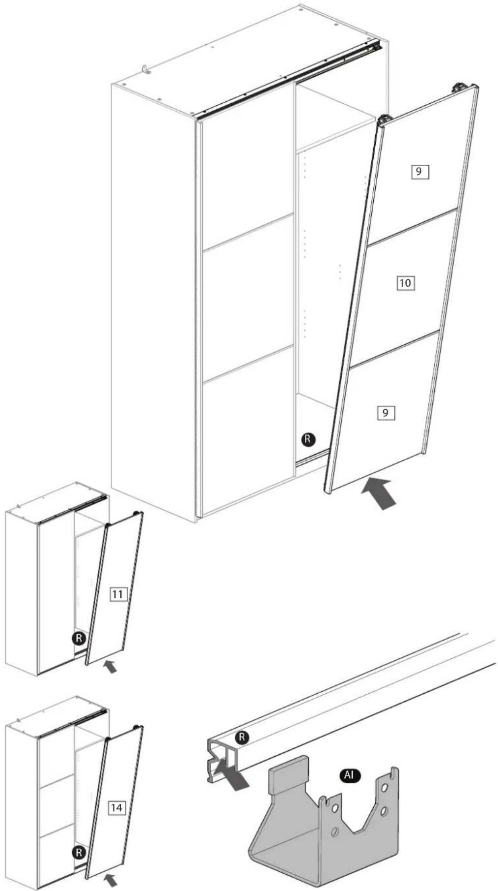
text_image
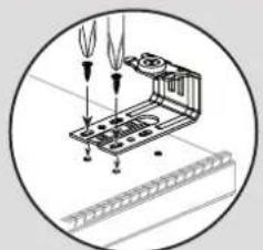
Technical diagram showing exploded and assembled views of a cabinet with numbered components and a metal bracket labeled 'AI'.18b
text_image
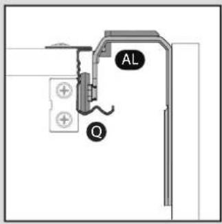
AL Q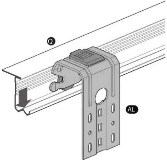
text_image
Q AL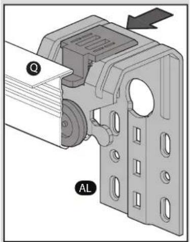
text_image
Q AL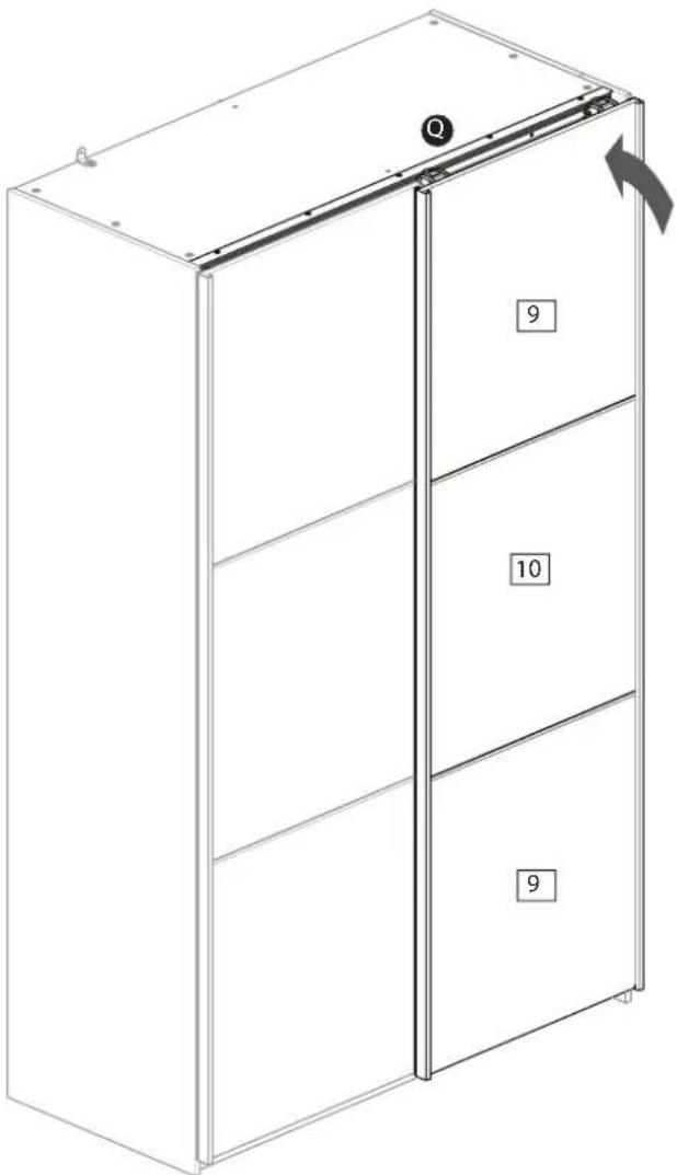
text_image
Q 9 10 9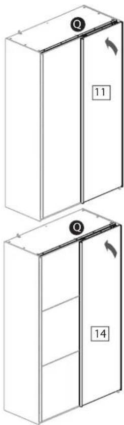
text_image
11 1419
text_image
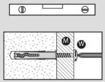
Technical diagram showing a mechanical assembly with labeled parts M and W, including a threaded rod and a fastener.