
RK4X - Système home cinéma Kramer - Notice d'utilisation et mode d'emploi gratuit
Retrouvez gratuitement la notice de l'appareil RK4X Kramer au format PDF.

| Type de produit | Adaptateur rack 19 pouces |
| Marque | Kramer |
| Modèle | RK4X |
| Catégorie | Système home cinéma (adaptateur rack) |
| Dimensions (approx.) | 48,3 cm (largeur) x 4,4 cm (hauteur 1U) x 15 cm (profondeur) |
| Poids (approx.) | 0,8 kg |
| Matériau | Métal (acier) |
| Compatibilité | Conçu pour monter le Kramer VS-4X (et autres machines compatibles) |
| Unités par adaptateur | 2 machines (selon le modèle) |
| Espace rack requis | 1U (unité rack) |
| Contenu du kit | Adaptateur, équerres, vis M3x8, écrous et rondelles, couvercle, manuel utilisateur |
| Installation | Montage en rack 19 pouces standard, nécessite tournevis cruciforme et allen |
| Fixation | Vis M3x8 noires Philips, vis coniques M3x6, écrous M3 |
| Utilisation | Montage d'appareils de bureau Kramer en rack professionnel |
| Température de fonctionnement | 0°C à 40°C |
| Garantie | 3 ans (pièces et main-d'œuvre) |
| Entretien et nettoyage | Essuyer avec un chiffon sec et doux. Ne pas utiliser de produits abrasifs. |
| Sécurité | Débrancher l'appareil avant installation. Utiliser uniquement les vis fournies. |
| Pièces détachées | Vis et équerres disponibles auprès du fabricant |
| Réparabilité | Réparation par un centre agréé Kramer |
FOIRE AUX QUESTIONS - RK4X Kramer
Questions des utilisateurs sur RK4X Kramer
0 question sur cet appareil. Repondez a celles que vous connaissez ou posez la votre.
Poser une nouvelle question sur cet appareil
Téléchargez la notice de votre Système home cinéma au format PDF gratuitement ! Retrouvez votre notice RK4X - Kramer et reprennez votre appareil électronique en main. Sur cette page sont publiés tous les documents nécessaires à l'utilisation de votre appareil RK4X de la marque Kramer.
MODE D'EMPLOI RK4X Kramer
Kramer Electronics, Ltd.
USER MANUAL
19-inch Rack Adapters
IMPORTANT: Before proceeding, please read paragraph entitled
"Unpacking and Contents"
Table Of Contents
Section Name Page
1 INTRODUCTION 2
-
HOW DO I GET STARTED? 2
-
UNPACKING AND CONTENTS 2
-
INSTALLATION 2
4.1 MOUNTING YOUR MACHINE IN THE RACK ADAPTER 2
-
THE ADAPTERS TABLE 3
-
The RK-10 Adapter Installation 5
-
The RK-MED Adapter Installation 6
-
The RK-MEDN Adapter Installation 7
-
The RK-50R Adapter Installation 8
-
The RK-50RN Adapter Installation 9
-
The RK-SM Adapter Installation 10
-
The RK-4E/S Adapter Installation 11
-
The RK-MED80 Adapter Installation 12
-
The RK-80 Adapter Installation 13
-
The RK-T1 Adapter Installation 15
-
The RK-T3 Adapter Installation 16
-
The RK-81 Adapter Installation 17
-
The RK-81X Adapter Installation 19
-
The RK-40 Adapter Installation 20
-
The RK-4X Adapter Installation 21
Limited Warranty 22
1 INTRODUCTION
Congratulations on your purchase of this Kramer Electronics Rack Adapter. Since 1981, Kramer has been dedicated to the development and manufacture of high quality video/audio equipment. The Kramer line has become an integral part of many of the best production and presentation facilities around the world. In recent years, Kramer has redesigned and upgraded most of the line, making the best even better. Kramer's line of professional video/audio electronics is one of the most versatile and complete available, and is a true leader in terms of quality, workmanship, price/performance ratio and innovation. In addition to the Kramer product you have just purchased, Kramer also offers a full line of high quality distribution amplifiers, switchers, processors, interfaces, controllers and computer-related products. This manual includes instructions for mounting your desktop machine in this 19-inch rack adapter.
2 HOW DO I GET STARTED?
The fastest way to get started is to take your time and do everything right the first time. Taking 15 minutes to read the manual may save you a few hours later. You don't even have to read the whole manual. If a section doesn't apply to you, you don't have to spend your time reading it.
3 UNPACKING AND CONTENTS
The items contained in your Kramer rack adapter package are listed below. Please save the original box and packaging materials for possible future shipment.
19-inch Adapter
Additional mechanical parts (screws, nuts etc.)
User Manual
Kramer Concise Product Catalog
4 INSTALLATION
4.1 Mounting your machine in the rack adapter
The rack adapter you have purchased is designed to help you install one of the Kramer's desktop machines into a standard 19" rack.
In this booklet, there are installation descriptions of all standard rack adapters of Kramer.
Before installing, you should do the following:
☒ Unpack the rack adapter kit.
☒ Have handy a Philips and an Allen screwdrivers.
Read carefully the following instructions.
☒ Disconnect the mains voltage and all cables connected to the machine that is being mounted in the rack adapter before proceeding with the installation.
^ = Old box - 24.5x18x4.5 cm (9.6"x7"x1.77")
* = New box -22× 18× 4.5 cm (8.66"x7"x1.77")
5 THE ADAPTERS TABLE
*** = Suitable only for the 1U adapter.
| Adapter Kramer Name | US Name | For Products Units | per adapter | Kramer catalog No. |
| VM-10 RK-10 VM-10AN, VS-6EII 1 60-100000 | ||||
| VPS-2U RK-MED 60-200000 | OP-1R, OP-1T, OP-2, SG-8, SG-9, SG-11, VA-15, VM-5AD, VM-9S, VM-40, VM-42, VP-3, VP-31, VP-102, VS-16A, VS-16N, VS-421, (VP-4, VS-24N)* | 1 | ||
| VPS-1U RK-MEDN | 60-200050 (new) | |||
| 50-55 2U RK-50R 60-500000 | FC-10, FC-10D, OC-1N, SG-6, TP-1N, TP-2N, TP-11N, TP-12N, VA-11, VA-12, VA-50P, VM-2N, VM-50A, VM-50H, VM-50YC, VM-50V, VP-2xl, VM-101, VS-55, VS-55A, VS-55V, VS-55YC | 2 | ||
| 50-55 1U RK-50RN | 60-500050 (new) | |||
| TP RK-SM TP-4 TP-5N, TP-6, VM-3AB, VM-3C, VM-3D, VM-3L, VM-3M, VM-3S, VM-3V, VS-33V | 3 60-300000 | |||
| VS-4E/S | RK-4E/S | VS-4E, VS-4YC | 2 | 60-400000 |
| SP-40 | RK-40 SP-40 | 1 60-400050 | ||
| 80A/80V | RK-MED80 | SP-4200, VM-80A, VM-80V, VM-9YC, VM-5S, VP-32xl(VP-4, VS-24N)** | 2 | 60-800000 |
| 80A/80V (new) | RK-80 | 60-800050 (new) | ||
| TOOLS 1U RK-T1 | 3 60-90000 | 0All Kramer Tools(103YC, 104L)*** | ||
| TOOLS 3U RK-T3 | 8 60-900050 | |||
| VS-81A/V/YC RK- | 81 VS-81A, | VS-81V, VS-81YC 2 60-810000 | ||
| VS-81X RK-81X | VS-81X 1 60-810050 | |||
| VS-4X RK-4X VS-4X 2 60-650000 | ||||
6 THE RK-10 ADAPTER INSTALLATION
This adapter is suitable for mounting the Kramer VM-10AN and VS-6EII into a 2U rack space.
- Remove the four rubber feet.
- Remove the cover (screws B).
- Drill 4 holes "A" ∅2.2mm in the cover (2 on each side).
- Insert the opened machine into the adapter.
- Replace the cover onto the machine and secure using the four screws "B".
- Fasten the adapter to the machine using four screws (into the newly drilled holes "A").
7 THE RK-MED ADAPTER INSTALLATION
This adapter is suitable for mounting the following Kramer machines into a 2U rack space: OP-1R, OP-1T, OP-2, SG-8, SG-9, SG-11, VA-15, VM-5AD, VM-9S, VM-40, VM-42, VP-3, VP-31, VP-102, VS-16A, VS-16N, VS-421, (VP-4, VS-24N, see note at table above)*
- Tighten holders using 4 black Allen M3x8.0 screws.
- Remove Philips black M3x4.0 screws.
- Insert machine into the adapter.
- Tighten machine using 2 Philips black M3x4.0 screws.
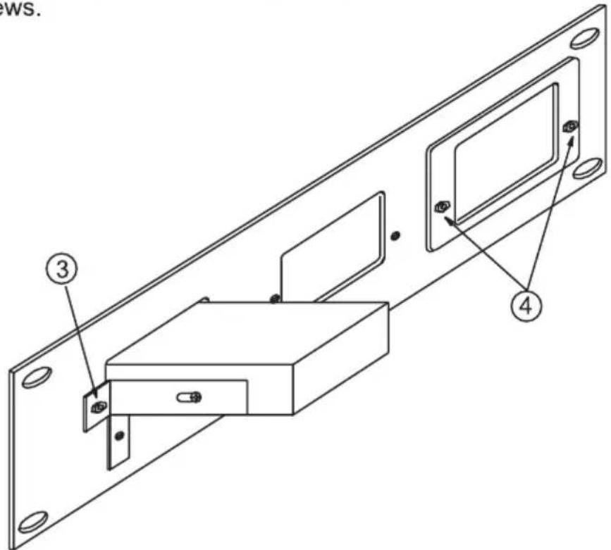
8 THE RK-MEDN ADAPTER INSTALLATION
This adapter is suitable for mounting the following Kramer machines into a 1U rack space: OP-1R, OP-1T, OP-2, SG-8, SG-9, SG-11, VA-15, VM-5AD, VM-9S, VM-40, VM-42, VP-3, VP-31, VP-102, VS-16A, VS-16N, VS-421, (VP-4, VS-24N, see note at table above)*
① REMOVE THE 2 SCREWS FROM THE RIGHT-HAND SIDE OF THE MACHINE.
② TIGHTEN THE BRACKET USING 2 M3x6 BLACK CONE SCREWS.
③ REMOVE THE 2 SCREWS FROM THE LEFT-HAND SIDE OF MACHINE.
④ TIGHTEN THE SECOND BRACKET USING 2 M3x6 BLACK CONE SCREWS.
9 THE RK-50R ADAPTER INSTALLATION
This adapter is suitable for mounting the following Kramer machines into a 2U rack space: FC-10, FC-10D, OC-1N, SG-6, TP-1N, TP-2N, TP-11N, TP-12N, VA-11, VA-12, VA-50P, VM-2N, VM-50A, VM-50H, VM-50YC, VM-50V, VP-2xl, VM-101, VS-55, VS-55A, VS-55V, VS-55YC.
- Remove the rubber feet from the bottom of the machine.
- Insert the machine into the adapter.
- Using the plastic nuts, attach the brackets to the machine.
- Using the metal screws, attach the brackets to the body of the adapter.
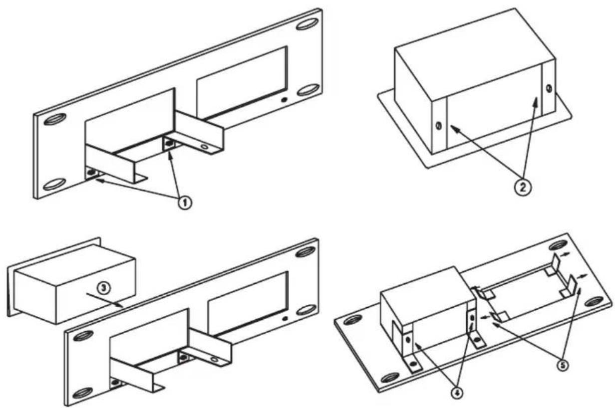
10 THE RK-50RN ADAPTER INSTALLATION
This adapter is suitable for mounting the following Kramer machines into a 1U rack space: FC-10, FC-10D, OC-1N, SG-6, TP-1N, TP-2N, TP-11N, TP-12N, VA-11, VA-12, VA-50P, VM-2N, VM-50A, VM-50H, VM-50YC, VM-50V, VP-2xl, VM-101, VS-55, VS-55A, VS-55V, VS-55YC.
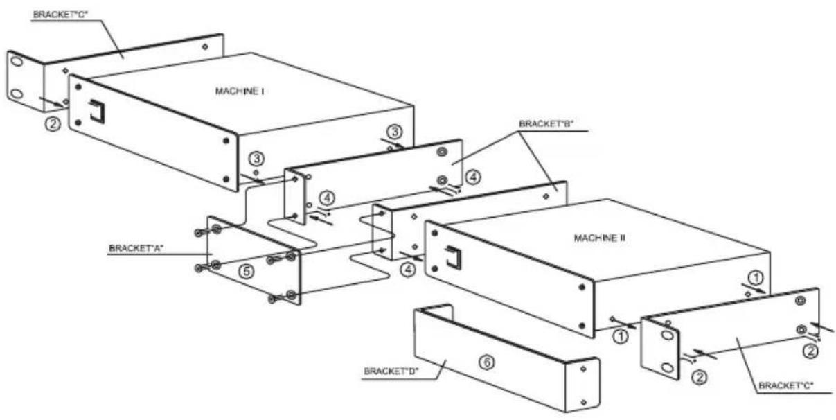
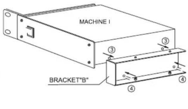
① REMOVE THE 2 SCREWS FROM THE LEFT-HAND SIDE OF MACHINE I, AND FROM THE RIGHT-HAND SIDE OF MACHINE II.
② TIGHTEN THE 2 BRACKETS "C" USING 4 M3x6 BLACK CONE SCREWS (SUPPLIED WITH BRACKETS).
③ TAKE OUT 2 SCREWS FROM THE OTHER SIDE OF EACH MACHINE.
④ TIGHTEN THE 2 BRACKETS "B" USING 4 M3x6 BLACK CONE SCREWS.
⑤ TIGHTEN BRACKET "A" USING 4 M3x6 BLACK CONE SCREWS.
⑥ BRACKET "D" IS PROVIDED TO COVER ONE OF THE OPENINGS IF THE ADAPTER IS USED WITH ONLY ONE MACHINE.
11 THE RK-SM ADAPTER INSTALLATION
This adapter is suitable for mounting the following Kramer machines into a 2U rack space: TP-4, TP-5N, TP-6, VM-3AB, VM-3C, VM-3D, VM-3L, VM-3M, VM-3S, VM-3V, VM-3Sxl, VM-3Vxl, VS-33V.
flowchart
graph TD
    A[" "] --> B[" "]
    C[" "] --> D[" "]
    E[" "] --> F[" "]
    G[" "] --> H[" "]
natural_image
Technical line drawing of a mechanical bracket with mounting flanges and a labeled component (no text or symbols)- Remove 2 Philips black M3x4.0 screws.
- Tighten "holders" using 2 Philips black M3x4.0 screws as drawn.
- Tighten machine to panel using 2 black Allen M3x8.0 screws.
- If necessary, insert cover and tighten using 2 black Allen M3x8.0 screws.
12 THE RK-4E/S ADAPTER INSTALLATION
This adapter is suitable for mounting the following Kramer machines into a 2U rack space: VS-4E, VS-4YC.
- Tighten holders using 2 black Allen M3x8.0 screws.
- Remove 2 Philips 4x1/4" screws.
- Insert machine into adapter.
- Tighten the machine using 2 Philips 4x1/4" screws.
- If necessary, insert the cover and bend the "ears".
13 THE RK-MED80 ADAPTER INSTALLATION
This adapter is suitable for mounting the following Kramer machines into a 1U rack space: SP-4200, VM-80A, VM-80V,VM-9YC, VM-5S, VP-32xl (VP-4, VS-24N, see note above)**.
-
Remove the 4 M3x8.0 allen screws. ①
-
Remove the nut and lock washer
- Tighten the machines using M3x8.0 black Allen screws.
- Tighten nut and lock washer.
- Tighten bracket using 2 M3x4.0 black Philips screws.
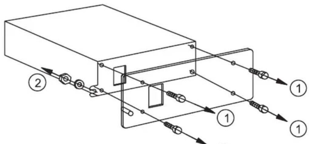
14 THE RK-80 ADAPTER INSTALLATION
This adapter is suitable for mounting the following Kramer machines into a 1U rack space: SP-4200, VM-80A, VM-80V, VM-9YC, VM-5S, VP-32xl (VP-4, VS-24N, see note above)**.
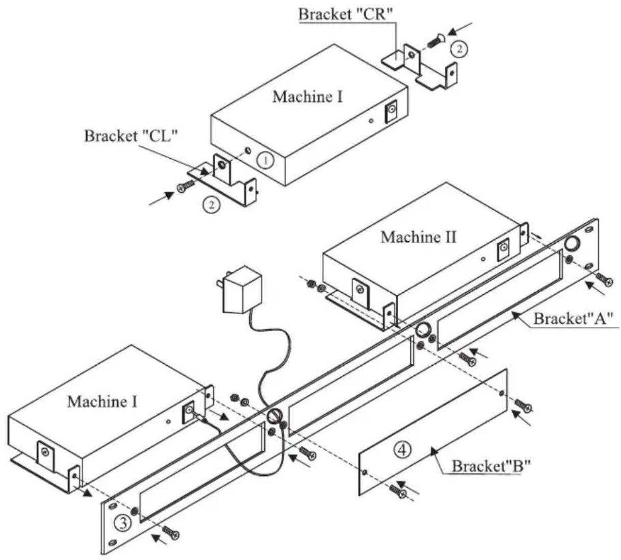
① REMOVE THE 2 SCREWS FROM THE LEFT-HAND SIDE OF MACHINE I.
② TIGHTEN THE BRACKET "A" USING 2 M3x6 BLACK CONE SCREWS.*
③TAKE OUT 2 M3x4 BLACK PHILLIPS SCREWS FROM OTHER SIDE OF MACHINE I.
④ TIGHTEN THE BRACKET "B" USING 2 M3x4 BLACK PHILLIPS SCREWS.
* BLACK CONE SCREWS SUPPLIED WITH BRACKETS.
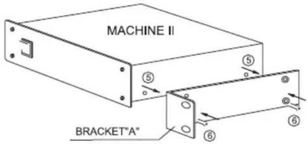
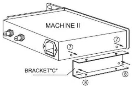
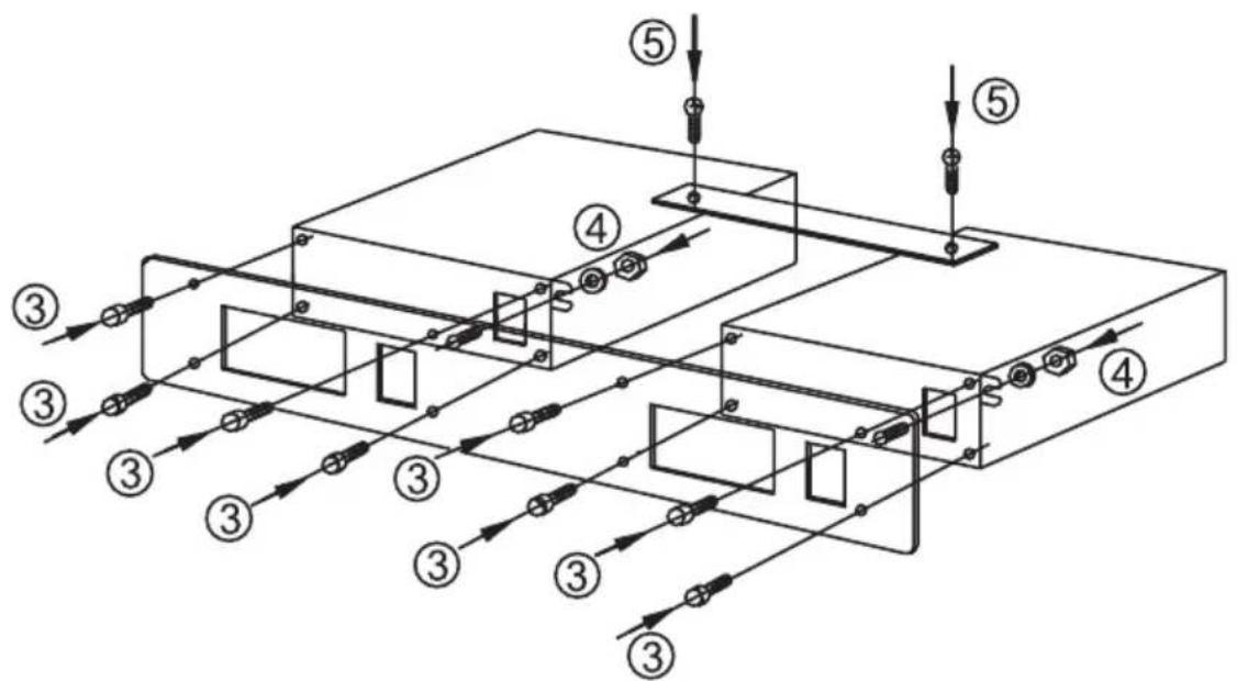
⑤ REMOVE THE 2 SCREWS FROM THE RIGHT-HAND SIDE OF MACHINE II.
⑥ TIGHTEN THE BRACKET "A" USING 2 M3x6 BLACK CONE SCREWS.
⑦ TAKE OUT 2 M3x4 BLACK PHILIPS SCREWS FROM OTHER SIDE OF MACHINE II.
⑧ TIGHTEN THE BRACKET "C" USING 2 M3x4 BLACK PHILIPS SCREWS.
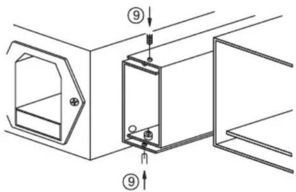
⑨ CONNECT BOTH MACHINES, AS SHOWN AND TIGHTEN USING 4 M3x4 BLACK PHILIPS SCREWS.
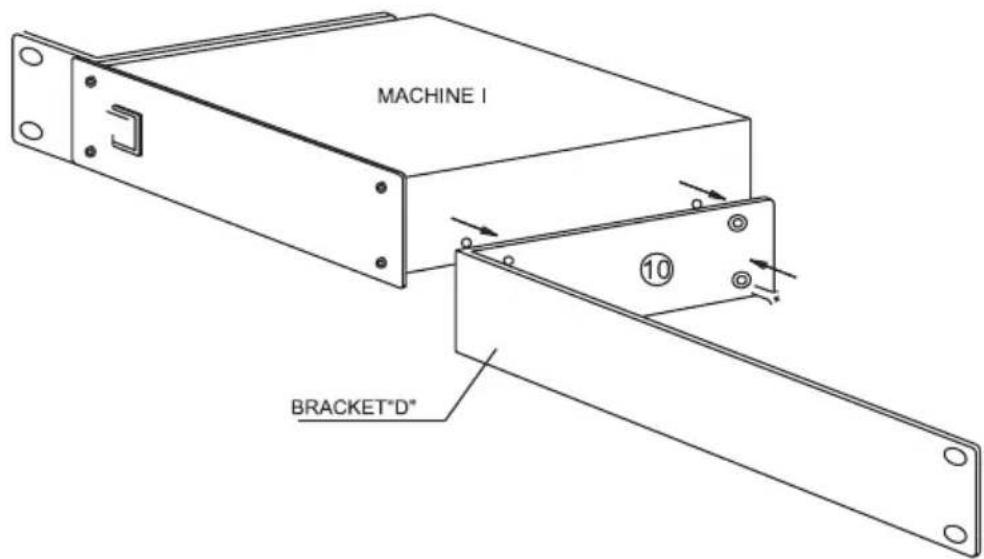
⑩ A BRACKET "D" IS PROVIDED TO COVER ONE OF THE OPENINGS IF THE ADAPTER IS TO BE USED FOR ONLY ONE MACHINE. REMOVE THE 2 SCREWS FROM THE RIGHT- HAND SIDE OF MACHINE I (OR FROM THE LEFT-HAND SIDE OF MACHINE II) AND TIGHTEN BRACKET "D" USING 2 M3x6 BLACK CONE SCREWS.
15 THE RK-T1 ADAPTER INSTALLATION
This adapter is suitable for mounting all the Kramer Tools machines into a 1U rack space.
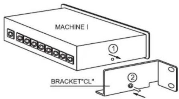
METHOD OF ASSEMBLY
① Remove the screw from the left hand side and from the right hand side of Machine I
② Tighten the Brackets "CL" and "CR" osing M3x6 black cone screws
③ Tighten Bracket "A" using M3x8 black Phillips screws (supplied with the bracket)
④ An additional BRACKET "B" is provided to cover one of the openings when only two machines are installed in the adapter.
16 THE RK-T3 ADAPTER INSTALLATION
This adapter is suitable for mounting all the Kramer Tools machines (besides the 103YC and 104L) into a 3U rack space.
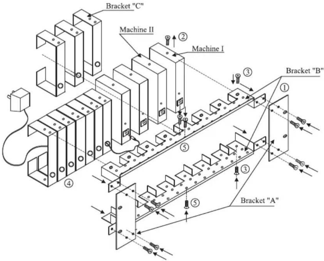
METHOD OF ASSEMBLY
① Tighten the 2 brackets "B" and the 2 brackets "A" using 8 M3x6 black Phillips screws (supplied with the brackets)
② Remove the screw from the left-hand side and from the right hand side of each machine (Kramer "TOOL")
③ Tighten the machines and brackers "B" using 2 M3x6 black cone screws
④ Tighten the brackets "C" and brackets "B" using 3 M3x8 black Phillips screws
⑤ To fill up empty unused spaces use brackets "C"
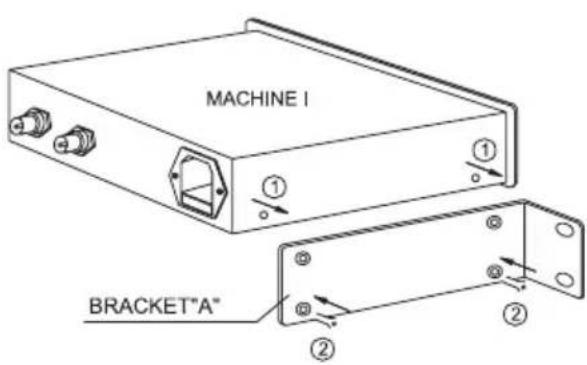
17 THE RK-81 ADAPTER INSTALLATION
This adapter is suitable for mounting the following Kramer machines into a 1U rack space: VS-81A, VS-81V, VS-81YC.
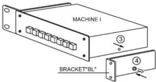
① REMOVE THE SCREW FROM THE LEFT- HAND SIDE OF MACHINE I.
② TIGHTEN THE BRACKET "CL" USING A M3x6.0 BLACK CONE SCREW.*
③ TAKE OUT THE SCREW FROM OTHER SIDE OF MACHINE I.
④ TIGHTEN THE BRACKET "BL" USING A M3x6.0 BLACK CONE SCREW.
* BLACK CONE SCREWS SUPPLIED WITH BRACKETS.
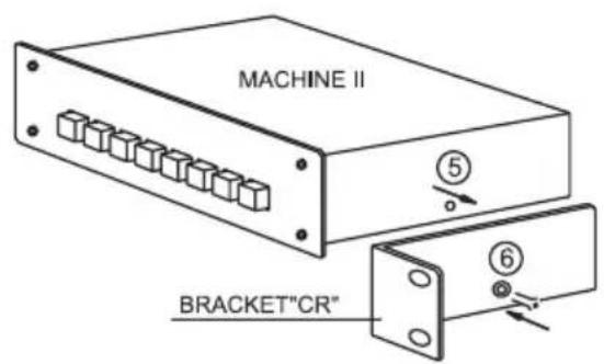
⑤ REMOVE THE SCREW FROM THE RIGHT- HAND SIDE OF MACHINE II.
⑥ TIGHTEN THE BRACKET "CR" USING A M3x6.0 BLACK CONE SCREW.
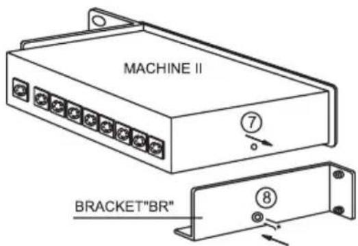
⑦ REMOVE THE SCREW FROM OTHER SIDE OF MACHINE II.
⑧ TIGHTEN THE BRACKET "BR" USING A M3x6.0 BLACK CONE SCREW.
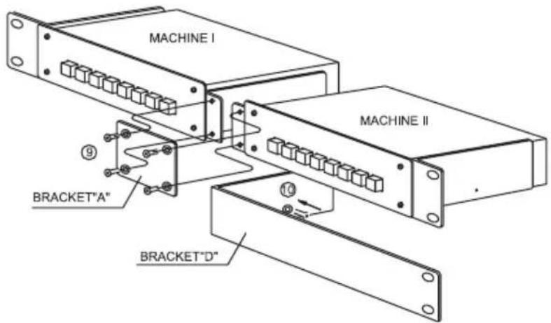
⑨ TIGHTEN BRACKET "A" USING 4 M3x6 BLACK CONE SCREWS.
⑩ A BRACKET "D" IS PROVIDED TO COVER ONE OF THE OPENINGS IF THE ADAPTER IS USED FOR ONLY ONE MACHINE. TIGHTEN BRACKET "D" TO THE RIGHT-HAND SIDE OF MACHINE I USING M3x6 BLACK CONE SCREW.
18 THE RK-81X ADAPTER INSTALLATION
This adapter is suitable for mounting the following Kramer machine into a 1U rack space: VS-81X.
① REMOVE THE 2 SCREWS FROM THE LEFT AND RIGHT-HAND SIDES OF COVER.
② TIGHTEN THE BRACKETS USING FOUR M3x6 BLACK CONE SCREWS AS DRAWING.
(BLACK CONE SCREWS SUPPLIED WITH BRACKETS.)
19 THE RK-40 ADAPTER INSTALLATION
This adapter is suitable for mounting the following Kramer machine into a 1U rack space: SP-40.
① REMOVE THE 2 SCREWS FROM THE LEFT AND RIGHT-HAND SIDES OF COVER.
② TIGHTEN THE BRACKETS USING FOUR M3x6 BLACK CONE SCREWS AS DRAWING.
(BLACK CONE SCREWS SUPPLIED WITH BRACKETS.)
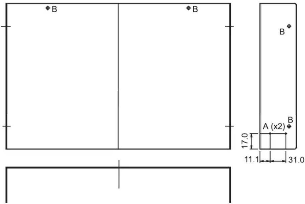
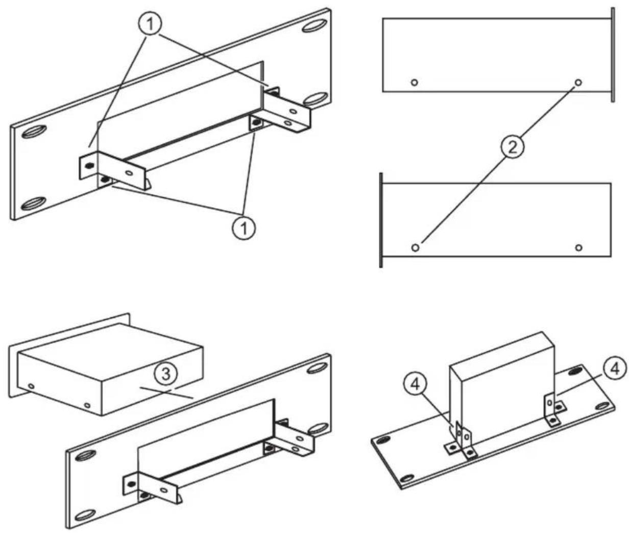
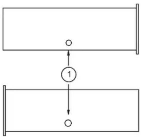
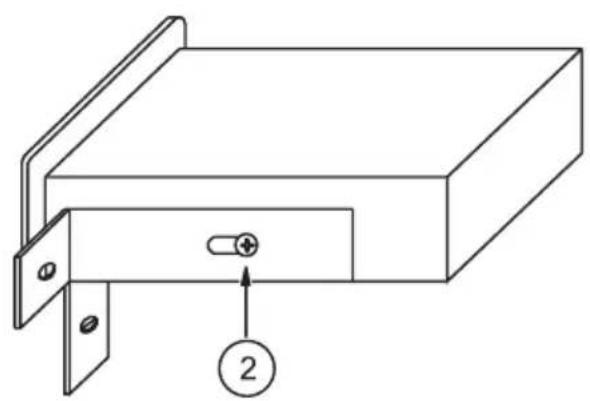
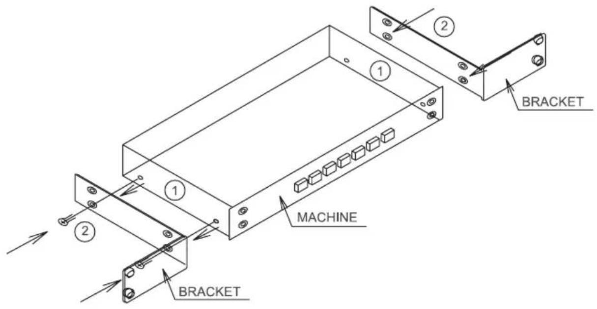
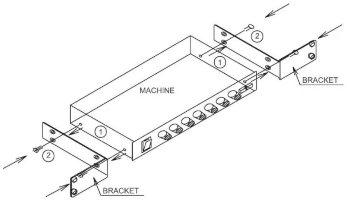
20 THE RK-4X ADAPTER INSTALLATION
This adapter is suitable for mounting the following Kramer machine into a 1U rack space: VS-4X.
ASSEMBLY PROCEDURE
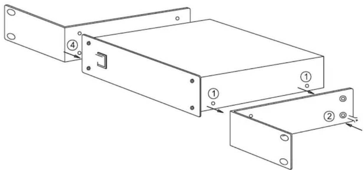
① INSERT THE MACHINE INTO THE ADAPTER.
② LOOSEN THE 2 SCREWS ON EACH SIDE OF THE MACHINE.
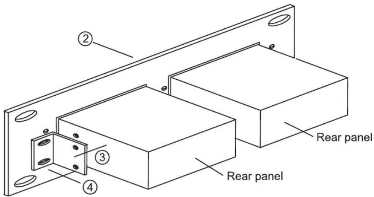
③ INSERT 2 BRACKETS SO THAT THE SLOT OF EACH BRACKET, WILL BE BETWEEN THE MACHINE AND THE HEAD OF THE SCREWS.
④ TIGHTEN THE 2 BRACKETS TO THE ADAPTER USING M3x8 SCREW PHILIPS BLACK.
⑤ TIGHTEN THE 2 SIDE SCREWS WITH FLEXIBLE SCREWDRIVER (IF NECESSARY).
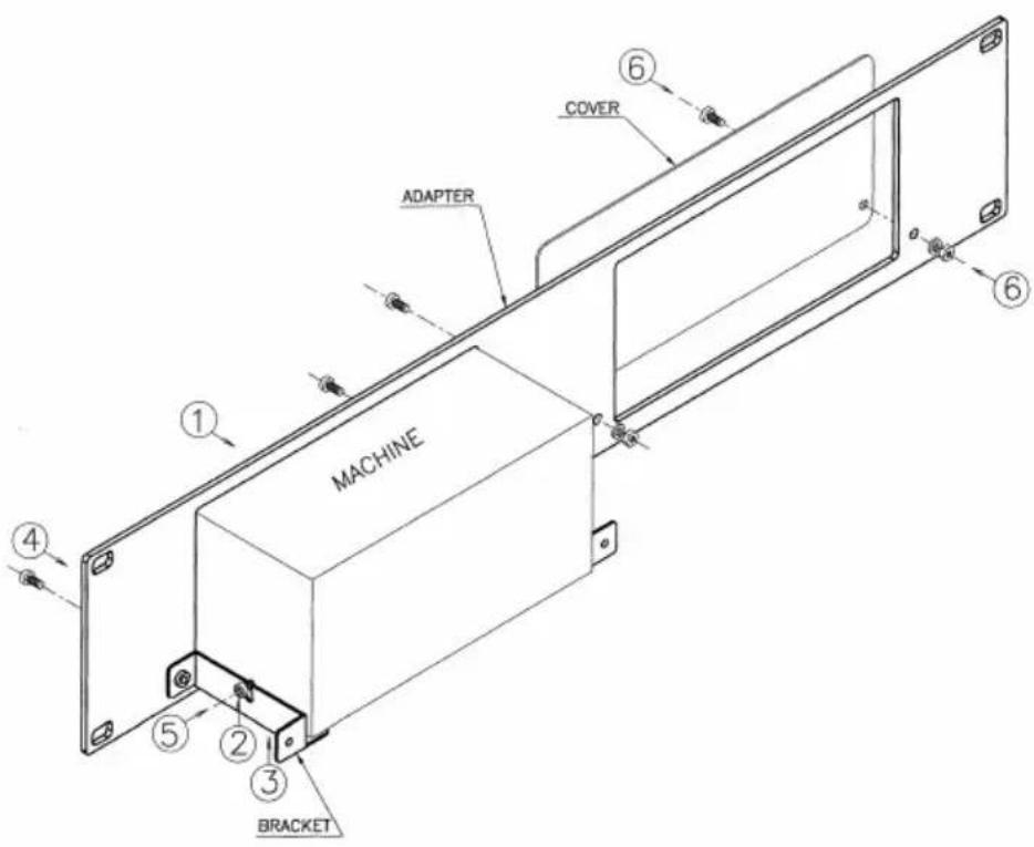
⑥ IF NO MACHINE IS USED IN OTHER LOCATION TIGHTEN THE PROVIDED COVER TO THE ADAPTER USING 2 M3x8 SCREWS PHILIPS BLACK, 2 NUTS AND 2 LOCK WASHER.
* M3x8 SCREWS PHILIPS BLACK, NUTS M3 AND LOCK WASHER M3 ARE SUPPLIED WITH THE ADAPTER.
LIMITED WARRANTY
Kramer Electronics (hereafter Kramer) warrants this product free from defects in material and workmanship under the following terms.
HOW LONG IS THE WARRANTY
Labor and parts are warranted for three years from the date of the first customer purchase.
WHO IS PROTECTED
Only the first purchase customer may enforce this warranty.
WHAT IS COVERED AND WHAT IS NOT COVERED
Except as below, this warranty covers all defects in material or workmanship in this product. The following are not covered by the warranty:
1) Any product which is not distributed by Kramer, or which is not purchased from an authorized Kramer dealer. If you are uncertain as to whether a dealer is authorized, please contact Kramer at one of the agents listed in the web site www.kramerelectronics.com.
2) Any product, on which the serial number has been defaced, modified or removed.
3) Damage, deterioration or malfunction resulting from:
a) Accident, misuse, abuse, neglect, fire, water, lightning or other acts of nature.
b) Product modification, or failure to follow instructions supplied with the product.
c) Repair or attempted repair by anyone not authorized by Kramer.
d) Any shipment of the product (claims must be presented to the carrier).
e) Removal or installation of the product.
f) Any other cause, which does not relate to a product defect.
g) Cartons, equipment enclosures, cables or accessories used in conjunction with the product.
WHAT WE WILL PAY FOR AND WHAT WE WILL NOT PAY FOR
We will pay labor and material expenses for covered items. We will not pay for the following:
1) Removal or installations charges.
2) Costs of initial technical adjustments (set-up), including adjustment of user controls or programming. These costs are the responsibility of the Kramer dealer from whom the product was purchased.
3) Shipping charges.
HOW YOU CAN GET WARRANTY SERVICE
1) To obtain service on you product, you must take or ship it prepaid to any authorized Kramer service center.
2) Whenever warranty service is required, the original dated invoice (or a copy) must be presented as proof of warranty coverage, and should be included in any shipment of the product. Please also include in any mailing a contact name, company, address, and a description of the problem(s).
3) For the name of the nearest Kramer authorized service center, consult your authorized dealer.
LIMITATION OF IMPLIED WARRANTIES
All implied warranties, including warranties of merchantability and fitness for a particular purpose are limited in duration to the length of this warranty.
EXCLUSION OF DAMAGES
Kramer's liability for any defective products is limited to the repair or replacement of the product at our option. Kramer shall not be liable for:
1) Damage to other property caused by defects in this product, damages based upon inconvenience, loss of use of the product, loss of time, commercial loss; or:
2) Any other damages, whether incidental, consequential or otherwise. Some countries may not allow limitations on how long an implied warranty lasts and/or do not allow the exclusion or limitation of incidental or consequential damages, so the above limitations and exclusions may not apply to you.
This warranty gives you specific legal rights, and you may also have other rights, which vary from place to place. NOTE: All products returned to Kramer for service must have prior approval. This may be obtained from your dealer.
For the latest information on our products and a list of Kramer distributors, visit our Web site: www.kramerelectronics.com.
Updates to this user manual may be found at http://www.kramerelectronics.com/manuals.html. We welcome your questions, comments and feedback.

C €
- Kramer Electronics, Ltd.
- USER MANUAL
- 19-inch Rack Adapters
- Table Of Contents
- Section Name Page
- INTRODUCTION
- HOW DO I GET STARTED?
- UNPACKING AND CONTENTS
- 19-inch Adapter
- INSTALLATION
- Mounting your machine in the rack adapter
- THE RK-10 ADAPTER INSTALLATION
- THE RK-MED ADAPTER INSTALLATION
- THE RK-MEDN ADAPTER INSTALLATION
- THE RK-50R ADAPTER INSTALLATION
- THE RK-50RN ADAPTER INSTALLATION
- THE RK-SM ADAPTER INSTALLATION
- THE RK-4E/S ADAPTER INSTALLATION
- THE RK-MED80 ADAPTER INSTALLATION
- THE RK-80 ADAPTER INSTALLATION
- THE RK-T1 ADAPTER INSTALLATION
- METHOD OF ASSEMBLY
- THE RK-T3 ADAPTER INSTALLATION
- THE RK-81 ADAPTER INSTALLATION
- THE RK-81X ADAPTER INSTALLATION
- THE RK-40 ADAPTER INSTALLATION
- THE RK-4X ADAPTER INSTALLATION
- ASSEMBLY PROCEDURE
- LIMITED WARRANTY
- HOW LONG IS THE WARRANTY
- WHO IS PROTECTED
- WHAT IS COVERED AND WHAT IS NOT COVERED
- WHAT WE WILL PAY FOR AND WHAT WE WILL NOT PAY FOR
- HOW YOU CAN GET WARRANTY SERVICE
- LIMITATION OF IMPLIED WARRANTIES
- EXCLUSION OF DAMAGES
Marque : Kramer
Modèle : RK4X
Catégorie : Système home cinéma