MicroStation V8 - Logiciel audio et/ou vidéo Bentley - Notice d'utilisation et mode d'emploi gratuit
Retrouvez gratuitement la notice de l'appareil MicroStation V8 Bentley au format PDF.
| Marque | Bentley |
| Modèle | MicroStation V8 |
| Type de produit | Logiciel de conception assistée par ordinateur (CAO) |
| Catégorie | Logiciel audio et/ou vidéo |
| Version | V8 |
| Système d'exploitation | Windows |
| Formats de fichier pris en charge | DGN, DWG, DGNlib, CSV |
| Fonctions principales | Dessin 2D et 3D, gestion des niveaux, accrochage intelligent, AccuDraw, placement d'éléments (lignes, arcs, cercles, ellipses, polygones), manipulation et modification d'éléments, cellules, références, hachures, courbes B-spline, modélisation de surfaces solides, filtres de niveaux, systèmes de coordonnées auxiliaires |
| Nombre de pages de la notice | 856 |
| Langue de la notice | Français (traductions disponibles) |
| Entretien et nettoyage | Mises à jour logicielles régulières, sauvegarde des paramètres et des fichiers de conception |
| Sécurité | Protection par mot de passe des fichiers DGN, gestion des droits d'accès via les niveaux |
| Pièces détachées et réparabilité | Non applicable (logiciel) |
| Informations générales | Marques déposées : AccuDraw, Bentley, MicroStation, MDL, SmartLine ; Copyright ©2001 Bentley Systems, Incorporated. |
FOIRE AUX QUESTIONS - MicroStation V8 Bentley
Questions des utilisateurs sur MicroStation V8 Bentley
0 question sur cet appareil. Repondez a celles que vous connaissez ou posez la votre.
Poser une nouvelle question sur cet appareil
Téléchargez la notice de votre Logiciel audio et/ou vidéo au format PDF gratuitement ! Retrouvez votre notice MicroStation V8 - Bentley et reprennez votre appareil électronique en main. Sur cette page sont publiés tous les documents nécessaires à l'utilisation de votre appareil MicroStation V8 de la marque Bentley.
MODE D'EMPLOI MicroStation V8 Bentley
MicroStation V8
natural_image
Abstract geometric shape composed of two overlapping triangles with a horizontal line (no text or symbols)User Guide
DAA016830-1/0002
BENTLEY
Trademarks
AccuDraw, Bentley, the "B" Bentley logo, MDL, MicroStation, MicroStation/J, QuickVision, and SmartLine are registered trademarks; PopSet and Raster Manager are trademarks; Bentley SELECT is a service mark of Bentley Systems, Incorporated or Bentley Software, Inc.
Java and all Java-based trademarks and logos are trademarks or registered trademarks of Sun Microsystems, Inc. in the U.S. and other countries.
Adobe, the Adobe logo, Acrobat, the Acrobat logo, Distiller, Exchange, and PostScript are trademarks of Adobe Systems Incorporated.
Windows is a registered trademark of Microsoft ^® Corporation.
Other brands and product names are the trademarks of their respective owners.
United States Patent Nos. 5,815,415, 5,784,068 and 6,199,125.
Copyrights
©2001 Bentley Systems, Incorporated. MicroStation ©1998 Bentley Systems, Incorporated. IGDS file formats ©1981-1988 Intergraph Corporation. Intergraph Raster File Formats ©1993 Intergraph Corporation. Portions ©1992-1994 Summit Software Company. Portions ©1992-1997 Spotlight Graphics, Inc. Portions ©1993-1995 Criterion Software Ltd. and its licensors. Portions ©1992-1998 Sun MicroSystems, Inc. Portions © Unigraphics Solutions, Inc. Icc ©1991-1995 by AT&T, Christopher W. Fraser, and David R. Hanson. All rights reserved. Portions ©1997–1999 HMR, Inc. All rights reserved. Portions ©1992–1997 STEP Tools, Inc. Sentry Spelling-Checker Engine ©1993 Wintertree Software Inc. Unpublished – rights reserved under the copyright laws of the United States and other countries. All rights reserved.
MicroStation User Guide
Table of Contents
1. The Level System
Levels 1-1
SettingtheActiveLevel 1-2
Controlling Level Display 1-5
Changing the Level of an Element 1-9
ManagingLevels 1-11
Creating and deleting levels 1-11
Modifying level attributes 1-14
Defining and deleting filters 1-16
Showing/Hidingcolumnsoinformation.... 1-22
SharingLevelDefinitions 1-23
2. Placing Elements in 2D
SettingtheActiveElementAttributes.... 2-1
Whatareelementattributes? 2-1
Elementsymbology 2-2
Color 2-2
Line Weight 2-4
LineStyle 2-6
Linestyle modifiers 2-6
General Procedure—Touseacustomlinestyle 2-7
Activating line style modifiers 2-9
Standardlinestyles 2-10
Levelsymbology 2-11
Otherelementattributes 2-13
Fill.... 2-13
Class 2-15
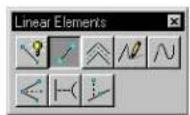
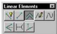
Linear Elements tool box 2-15
PlaceSmartLine 2-17
Place Line 2-23
PlaceMulti-line 2-24
Place Stream Line String 2-27
Place Point or Stream Curve 2-29
ConstructAngleBisector 2-31
MicroStation User Guide i
ConstructMinimumDistanceLine 2-32
Construct Line at Active Angle 2-33
Ellipsestoolbox.... 2-35
Place Circle 2-36
Place Ellipse 2-39
Polygonstoolbox 2-43
PlaceBlock 2-44
Place Shape 2-46
Place Orthogonal Shape 2-48
Place Regular Polygon 2-50
SettingtheActivePoint 2-53
Pointstoolbox 2-54
PlaceActivePoint 2-56
ConstructPointsBetweenDataPoints 2-57
ProjectActivePointOntoElement 2-59
ConstructActivePointatIntersection.... 2-61
ConstructPointsAlongElement 2-62
ConstructActivePointatDistanceAlongElement 2-64
Arcstoolbox.... 2-66
PlaceArc 2-67
PlaceHalfEllipse 2-70
Place Quarter Ellipse 2-71
ModifyArcRadius 2-72
ModifyArcAngle 2-73
ModifyArcAxis 2-74
Using the Select Settings Window 2-75
Components 2-77
General Procedure — To work with drawing settings groups ..... 2–77
Otheregoriesofsettingsgroups.... 2-78
Scale settings groups 2-78
Working units settings groups 2-79
3. Drawing Technique
Identifying Elements 3-2
Identifying elements manually 3-2
AccuSnap 3-2
Automatic identification of elements 3-2
Pop-upInfo 3-3
Snapping to Points on Elements 3-3
Tentative snap points 3-3
Snappingtotentativepointsonelements 3-4
Using AccuSnap 3-13
Turning AccuSnap On or Off 3-14
AccuSnapsettings 3-15
AccuSnap and Snap Modesettings.... 3-17
Using Tentative Points 3-24
Working with AccuDraw 3-26
AsimpleexampleofusingAccuDraw 3-27
ActivatingAccuDraw 3-30
AccuDraw'scompass 3-31
The origin point 3-32
Theframe(drawingplaneindicator) 3-32
The X/Y axes 3-33
AccuDraw's drawing plane 3-34
Drawingplanecoordinatesystems 3-35
The AccuDraw window 3-36
AccuDraw's window and the input focus 3-36
AccuDraw's Settingsdialogbox.... 3-37
Controlling and using AccuDraw 3-37
Previewingandconstrainingdatapoints 3-39
How AccuDraw reacts to pointer movement 3-39
Tolerance setting 3-40
Previous distancerecall.... 3-42
Recallingpreviousvalues 3-43
Settings manipulation 3-43
AccuDraw and the Popup Calculator 3-44
Performingsimpleoperations 3-45
Advanced uses of the pop-up calculator 3-47
AccuDraw'sshortcutkey-ins 3-48
AccuDrawdefaults.... 3-50
Create,editanddeleteshortcuts 3-50
General Procedure — To activate a shortcut key-in .... 3–51
SmartLock 3-52
X and Y locks 3-55
Distance lock 3-55
Anglelock 3-56
Unit roundoffs and their effect on AccuDraw 3-57
Distanceroundoff.... 3-58
Angleroundoff 3-58
Moving the Accu Drawcompass 3-59
The floating origin option 3-59
AccuDraw and the tentative point 3-60
AccuDraw's drawing plane orientation 3-62
Rotating the drawing plane axes in 2D 3-63
Rotation-sensitivetools 3-63
The Rotate Quick Shortcut Key-in 3-64
Using shortcut snap modes with AccuDraw 3-65
The AccuDraw-enhanced Nearest snap mode 3-65
Settingthekeypointsnapdivisor 3-66
AccuDraw's Effecton Various Tools 3-67
AccuDraw and the Place Circle tool 3-67
AccuDraw and the Place Arc tool 3-68
AccuDraw and the Place Ellipse tool 3-69
AccuDraw and the Place Block tool 3-69
AccuDraw and the Place SmartLine Tool 3-70
AccuDrawaffectsmosttools 3-72
Complete List of AccuDraw Shortcut Key-ins 3-73
SelectingElements 3-76
Manipulating and Modifying Selected Elements 3-77
Using the Fenceto Manipulate and Modify Elements 3-80
Specifying which elements are in the fence contents 3-81
Manipulationsonmanyelements.... 3-83
Optimizedfenceclipping 3-84
Special fence manipulations 3-85
Using the Grid 3-86
Grid Orientation.... 3-87
UsingGridLock 3-90
PrecisionInputKey-ins 3-91
Syntax notes 3-94
Measuretoolbox 3-95
MeasureDistance 3-97
MeasureRadius.... 3-100
MeasureAngleBetweenLines 3-101
Measure Length 3-102
Measure Area 3-103
Measure Volume 3-108
Mass Properties window 3-110
Basicproperties 3-112
4. Element Manipulation and Modification Tools
Using the Tools in the Element Selection tool box 4-1
Element Selection tool box 4-2
Element Selection 4-2
PowerSelector 4-5
SpecializedManipulationandModificationTools 4-11
Fence tool box 4-14
PlaceFence 4-15
Modify Fence 4-19
Manipulate Fence Contents 4-20
DeleteFenceContents 4-23
D r o p C o m p l e x S t a t u s o f F e n c e C o n t e n t s 4-24
Manipulatetoolbox 4-25
CopyElement 4-26
Move Element 4-29
MoveParallel.... 4-31
Scale 4-33
Rotate 4-40
Mirror.... 4-47
AlignEdges 4-50
ConstructArray 4-52
ChangeAttributestoolbox 4-56
ChangeElementAttributes 4-58
ChangeElementtoActiveArea 4-61
ChangeElementtoActiveFillType 4-63
Modify Line Style Attributes 4-64
CHANGELINESTYLESCALE 4-65
ACTIVELINESTYLESCALE 4-66
ChangeMulti-linetoActiveDefinition 4-67
MatchElementAttributes 4-68
MatchAllElementSettings 4-69
Match tool box 4-71
Match Text Attributes 4-72
MatchMulti-lineDefinition 4-73
Match Dimension Settings 4-74
Match Curve Settings 4-75
MatchSurfaceSettings 4-76
Droptoolbox 4-78
D r o p C o m p l e x S t a t u s 4-80
Drop Line String/Shape Status 4-81
Drop Text 4-82
DropAssociation 4-83
Drop Line Style 4-84
Drop Associative Pattern 4-85
DropMulti-line 4-86
Drop Dimension Element 4-87
Modify tool box 4-88
Modify Element 4-90
Delete Part of Element 4-101
ExtendLine 4-102
Extend Two Elements to Intersection 4-104
Extend Element to Intersection 4-105
Trim Element 4-106
IntelliTrim 4-107
InsertVertex 4-113
DeleteVertex 4-115
Construct Circular Fillet 4-116
Construct Chamfer 4-118
5. Using Cells
WorkingwithCellLibraries 5-2
Creating and Editing Cells 5-6
Cell type 5-7
ByCell 5-10
Placing Cells 5-10
Controlling the level on which cells are placed 5-12
Shared cells 5–13
What is a shared cell? 5-13
Reasons to use shared cells 5-13
Hatching and Patterning 5-29
Controlling the display of patterns 5-30
Placing patterns in the design 5-31
Associative patterns 5-32
Snappable patterns 5-33
Excluding areas inside a patterned area from patterning 5-33
Setting elements to be Solid or Hole 5-34
Using tool settings 5-34
Using Alternating Area to exclude nested areas from patterning 5-34
Manipulating/modifying excluded regions 5-35
Patterning disjointed regions 5-36
Cells used for patterning 5-36
Pattern cells supplied with MicroStation 5-36
Guidelines for creating pattern cells 5-38
Tolerance 5-38
Dimension-driven Cells 5-64
6. References
Using References 6-1
Attaching references 6-2
Attachments using saved views 6-4
Making portable reference attachments 6-9
Helping locate "lost" attachments 6-11
Attaching remote references 6-12
vi MicroStation User Guide
ReferenceAgent 6-13
Working with attached references 6–14
Identifying references 6-26
Merging reference DGN files 6-26
Settingtherendermodeofareference 6-28
Referencestoolbox 6-28
AttachReference 6-31
Set Reference Clip Boundary 6-32
Set Reference Clipping Mask 6-33
Delete Reference Clipping Mask(s) 6-33
Define Reference Back Clipping Plane 6-34
Define Reference Front Clipping Plane 6-35
ReloadReference 6-36
MoveReference 6-36
Copy Reference Attachment 6-37
ScaleReferences 6-38
RotateReference 6-39
MirrorReferences 6-40
SetReferencePresentation.... 6-41
Detach Reference 6-42
Adjusting the FileUpdateSequence 6-43
7. Advanced 2D Drafting Techniques
Permanently Grouping Elements 7-2
Using complex chains and complex shapes 7-2
Using groups 7-3
Using graphic groups 7-4
Putting "Holes" in Solid Elements 7-5
Filletstoolbox 7-6
ConstructParabolicFillet 7-7
Groupstoolbox 7-8
Drop Element 7-10
Create Complex Chain 7-12
Create Complex Shape 7-15
CreateRegion 7-18
Add to Graphic Group 7-22
D r o p f r o m G r a p h i c G r o u p 7-23
Group Holes 7-25
UsingMulti-lines.... 7-26
General Procedure — To define a multi-line .... 7–27
Dropping multi-lines 7-31
Multi-lineJointstoolbox 7-32
MicroStation User Guide vii
Construct Closed Cross Joint 7-35
ConstructOpenCrossJoint 7-36
ConstructMergedCrossJoint 7-37
CutSingleComponentLine 7-38
CutAllComponentLines 7-39
ConstructClosedTeeJoint 7-40
ConstructOpenTeeJoint 7-41
ConstructMergedTeeJoint 7-42
Construct Corner Joint 7-43
UncutComponentLines 7-44
Multi-linePartialDelete.... 7-45
MoveMulti-lineProfile 7-47
EditMulti-lineCap 7-49
Associating Elements 7-50
Elements that can be associated with other elements 7-50
Associatingcells 7-51
Associating multi-lines 7-51
Isometric Drawing.... 7-52
Isometric tool box 7-54
PlaceIsometricBlock 7-55
PlaceIsometricCircle 7-57
Using Curves 7-59
Pointcurves 7-60
B-splinecurves 7-60
Methods by which the curve is calculated 7-61
B-spline curve attributes 7-63
Special-purpose2DB-splinetools 7-66
Compositecurves 7-66
Bézier curves 7-67
Creating any conceivable curve 7-67
General Procedure — To place a pre-defined curve 7–68
General Procedure — To define a curve's formula 7-70
Examples 7-71
Dimensionality 7-71
Function format 7-72
Deriving a curve from an existing curve 7-72
CreateCurvestoolbox 7-74
Place B-spline Curve 7-75
Create Curve by Tangents 7-82
Place Composite Curve 7-85
Construct Interpolation by Arcs 7-89
Place Conic....7-91
Place Spiral 7-94
PlaceHelix 7-95
Offset Curve 7-97
ExtractIso-parametricLines 7-99
Curve Calculator 7-101
Curve Calculator dialog box 7-103
ModifyCurvestoolbox 7-109
ChangetoActiveCurveSettings 7-110
RebuildCurve 7-112
Extend Curve.... 7-114
ChangeElementDirection 7-116
Convert Element to B-spline 7-117
Blend Curves 7-119
Drop B-spline Curve 7-121
Flatten Curve 7-123
Deform Curve 7-126
Evaluate Curve 7-127
Selecting Elements BasedonAttributes 7-133
General Procedure — To use Attributes as Selection Criteria 7-133
UsingAuxiliaryCoordinateSystems 7-135
ACStoolbox 7-137
DefineACS(AlignedwithElement) 7-139
DefineACS(ByPoints) 7-140
DefineACS(AlignedwithView) 7-141
RotateActiveACS 7-142
Move ACS 7-143
SelectACS 7-144
Digitizing 7-144
Digitizing table partitioning.... 7-145
Placing monumentpoints 7-146
Tools for digitizing 7-148
Panningwhiledigitizing 7-148
8. 3D Design and Modeling
DWG Restrictionworkmodeand3D 8-2
Basic3D Concepts 8-2
Designcube 8-3
View volume 8-3
Display Depth 8-5
Active Depth 8-5
Standardviews 8-7
2D 8-7
3D Orthogonalviews 8-7
Isometricviews 8-9
MicroStation User Guide ix
View coordinates.... 8-10
Perspective projection 8-10
Using the grid in 3D....8-11
Viewinga3D model 8-12
3D viewing procedure st hataresimilarto2D 8-12
Fittingviewsin3D 8-13
Rotating views in 3D 8-13
Panningviewsin3D 8-15
3D-specificviewingprocedures 8-16
Usingsavedviewsin3D 8-16
View Control tool box 8-17
Zoom 8-20
ChangeViewPerspective 8-21
Set Display Depth 8-22
SetActiveDepth 8-25
Show Display Depth 8-27
ShowActiveDepth 8-28
Camera Settings 8-29
SetViewDisplayMode 8-34
Navigate Camera 8-36
Apply Clip VolumeToView 8-49
3D Elements 8-51
Open3Delements 8-52
Non-planarlinestringsandcurves 8-52
Helixes 8-52
3D Primitives 8-53
Slab 8-53
Sphere 8-53
Coneandcylinder 8-54
Torus 8-54
W e d g e 8-55
Extruded surfaces and surfaces of revolution 8-55
Free-form(NURBS)surfaces 8-56
3D Fillets 8-57
Drawingin3D 8-57
Placing elements in 3D 8-58
Specifyingwhetheranelementenclosesvolume 8-58
UsingAccuDrawin3D 8-59
The AccuDraw window in 3D 8-60
Orientingthedrawingplanein3D 8-60
Precision input key-ins in 3D 8-64
3D datapoints and 3D tentative points 8-65
3D auxiliary coordinate systems 8-66
ACSType 8-66
UsingAccuDrawwithauxiliarycoordinatesystems 8-69
Other way sof working with auxiliary coordinates systems 8-7
Manipulating and modifying elements in 3D 8-73
Selecting elements in 3D 8-74
Identifying existing elements 8-74
Using the fence in 3D 8-75
SmartSolids/SmartSurfaces 8-75
SettingsthataffectSmartSolids/SmartSurfaces.... 8-76
B-spline and 3D dialog box 8-76
Display 8-77
Surface/Solid Iso Lines 8-77
LocateByFace 8-78
UseOptimizedFenceClipping 8-79
Exportingvisibleedges 8-80
3DMaintoolframe 8-81
3D Primitives tool box 8-82
Place Slab 8-83
PlaceSphere 8-87
Place Cylinder 8-89
Place Cone 8-93
Place Torus 8-94
Place Wedge 8-98
3D Constructtoolbox 8-100
Extrude 8-101
Construct Revolution 8-107
ExtrudeAlongPath.... 8-109
ShellSolid 8-113
Thicken to Solid 8-116
3 D Modify toolbox 8-118
ModifySolid 8-120
Remove Faces and Heal 8-122
Taper Solid 8-126
ConstructUnion 8-128
Construct Intersection 8-130
ConstructDifference 8-133
Cut Solid 8-134
FilletEdges 8-138
ChamferEdges 8-140
Edit3D Primitive 8-143
3D Utility toolbox 8-144
Align Faces 8-146
ChangeSmartSolidDisplay 8-151
ExtractFaceorEdgeGeometry 8-154
Intersect Solid/Surface with Curve 8-157
ConstructFacet 8-159
SurfaceModelingtoolframe 8-161
CreateSurfacestoolbox 8-162
ConstructSurfacebySectionorNetwork 8-163
ConstructSurfacebyEdges 8-166
PlaceFree-formSurface 8-169
ConstructSkinSolid/Surface 8-174
SweepAlongTwoTraces 8-175
ConstructHelicalSurface 8-179
OffsetSurface 8-181
Modify Surface toolbox 8-182
ConstructTrim 8-184
ProjectTrim 8-187
Convert3D 8-190
Construct Stitch 8-191
ChangeNormalDirection 8-192
Untrim Surface 8-193
ChangetoActiveSurfaceSettings 8-195
SplitSurface 8-197
ExtendSurface 8-198
RebuildSurface 8-199
FilletSurfacestoolbox 8-202
FilletSurfaces 8-202
Blend Surfaces 8-205
Blend Surface Between Rail Curves 8-207
3D Queriestoolbox 8-210
Evaluate Surface 8-210
Analyze Curvature 8-215
Using Cellsin3D 8-216
Creating 3D cells 8-216
Patterningin3D 8-217
text_image
1The Level System
In this chapter, you will find procedures used for organizing and maintaining your data in logical levels. Each level is named and stored in the DGN file. The display of elements residing on particular levels can be turned on or off, as necessary, to display only the desired information. When MicroStation users refer to turning levels on and off or toggling their display, they really mean toggling the display of elements residing on those levels.
The topics in the chapter include:
• Levels (see page 1-1)
- Setting the Active Level (see page 1-2)
- Controlling level display (see page 1-5)
- Changing an element's level (see page 1-9)
• Managing levels (see page 1-11)
- Sharing level definitions (see page 1-23)
Levels
Each element in a model is on a drawing level. Levels are analogous to transparent overlays: In different combinations they make it easier to see parts of a model. You can create virtually an unlimited number of levels (4 billion) in a DGN file.

You can set up a level structure to make it easy to manipulate the display of various levels and save the level structure in a separate file to make it easier to use with other designs.

For more information about models, see "Models" in the QuickStart Guide.
Setting the Active Level
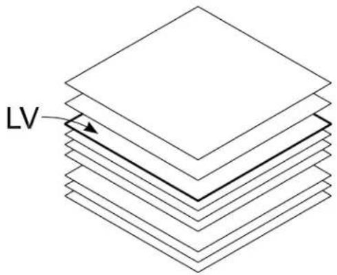
"LV" denotes the Active Level
The level on which new elements are placed in a model is that model's Active Level. The Active Level is the same level in all views.
text_image
LVThe name of the level to which the Active Level is set is shown in the Attributes tool box and the status bar.

If you neglect to save settings in the open DGN file, before closing it, changes to its models' level display settings will not be in effect the next time you open the file. For information about saving settings, see "Saving DGN file settings" in the QuickStart Guide.
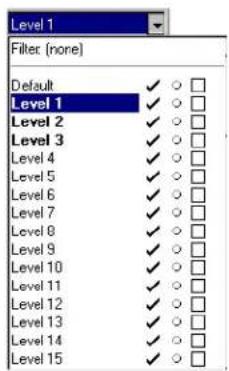
To set the Active Level using the Active Level combo box
- In the Attributes tool box, click the Active Level combo box.
Level option menu
text_image
Level 1 Filter (none) Default ✓ ○ □ Level 1 ✓ ○ □ Level 2 ✓ ○ □ Level 3 ✓ ○ □ Level 4 ✓ ○ □ Level 5 ✓ ○ □ Level 6 ✓ ○ □ Level 7 ✓ ○ □ Level 8 ✓ ○ □ Level 9 ✓ ○ □ Level 10 ✓ ○ □ Level 11 ✓ ○ □ Level 12 ✓ ○ □ Level 13 ✓ ○ □ Level 14 ✓ ○ □ Level 15 ✓ ○ □The combo box opens and the available levels are displayed.
- Choose the desired level to be the Active Level.
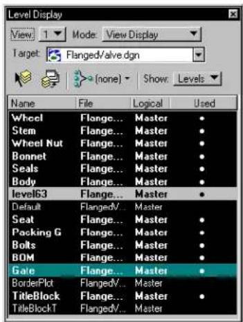
To set the Active Level using the Level Display dialog box
- Click the Level Display icon on the Primary Tools tool box. or From the Settings menu's Level submenu, choose Display.
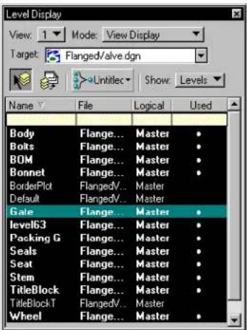
The Level Display dialog box opens. The active level is highlighted.
Level Display dialog box with the active level highlighted in green
text_image
Level Display View 1 Mode View Display Target: Flanged/valve.dgn (none) Show: Levels Name File Logical Used Wheel Flange... Master Stem Flange... Master Wheel Nut Flange... Master Bonnet Flange... Master Seals Flange... Master Body Flange... Master level63 Flange... Master Default FlangedV... Master Seat Flange... Master Packing G Flange... Master Bolts Flange... Master BOM Flange... Master Gate Flange... Master BorderPlot FlangedV... Master TitleBlock Flange... Master TitleBlockT FlangedV... Master- Double-click the level you want to make the active level.
The selected level appears as the active level on the Attributes tool box.
To set the Active Level with a key-in
- Key in ACTIVE LEVEL
To set the Active Level using the Level Manager
- From the Settings menu's Level submenu, choose Manager. or
Click the Active Level field on the status bar.
The Level Manager dialog box opens.
- Double-click the level you want to make the active level.
The selected level appears as the active level in the Level menu in the Attributes tool box.
Controlling Level Display
Use the Level Display dialog box to turn the display of levels on or off on a model by model basis.

If you neglect to save settings in the open DGN file, before closing it, changes to its models' level display settings will not be in effect the next time you open the file. For information about saving settings, see "Saving DGN File Settings" in the QuickStart Guide.
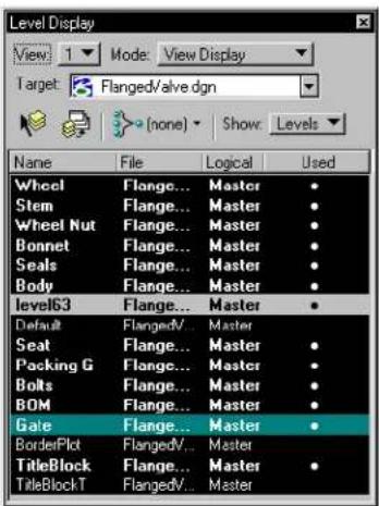
To open the Level Display dialog box
- Click the Level Display icon on the Primary Tools tool box.
or Press Ctrl-E or
From the Settings menu's Level submenu, choose Display.
The Level Display dialog box opens listing levels in the open DGN file.
text_image
Level Display View: 1 Mode: View Display Target: Flanged/valve.dgn (none) Show: Levels Name File Logical Used Wheel Flange... Master Stem Flange... Master Wheel Nut Flange... Master Bonnet Flange... Master Seals Flange... Master Body Flange... Master level63 Flange... Master Default Flanged/... Master Seat Flange... Master Packing G Flange... Master Bolts Flange... Master BOM Flange... Master Gate Flange... Master BorderPlot Flanged/... Master TitleBlock Flange... Master TitleBlockT Flanged/... MasterTo toggle the display of levels for references
- In the Level Display dialog box, from the Target combo box, choose the desired references.
The levels in the chosen reference display. Notice the File and Logical columns display the reference name and logical name.
- Click a level that is being used (i.e., highlighted with a dot in the Used column) in the open DGN file to toggle the level on/off.
If the level is on, the dot will change from white to black. If the level was off, the dot will change from black to white.
To toggle the display of levels in all views
- In the Level Display dialog box, click the Apply to All Views icon. or
Right-click in the Level list and select Apply to All Views on the pop-up menu.
The display of the select level toggles to its opposite state (on/off) in all views.
Use the Apply to All Views icon to apply level display changes temporarily.
To toggle the display of levels in all models stored in the open DGN file
- In the Level Display dialog box, click the Use Global check box.
The display of the selected level toggles (on/off) in all views in all models.
This has the same affect as toggling the check mark in the Global column on the Level Manager dialog box. All views have the same levels on/off while Use Global is on.
All views have the same levels on/off while Use Global is on.
To toggle the display of levels using the Active Level combo box
- Click the Active Level combo box in the Attributes tool box. See the "Attributes tool box" in the Reference Guide for more information.
The levels in the open DGN file are listed.
- Click the check mark next to the level on which you want to change the display.
The check mark changes to a circle indicating the level display is off. To turn the display back on, click the circle so the check mark reappears.
You cannot turn off the display of the Active Level if the Display Active Level in All Views preference is on in the Operation category of the (Workspace > Preferences). See “Preferences dialog box” in the Reference Guide for more information on how to set user preferences.
To change the display of levels graphically
-
In the Level Display dialog box, select the Change Level tool.
-
Identify an element (see page 3-2) residing on the level for which you want to change the display setting.
-
Enter a data point anywhere in any view except on an element to accept the element.
-
In the Change Level settings window, choose Display Off from the Level option menu to turn off the level(s) of the identified element. or
Choose Display Only from the Level option menu to display only the level(s) of the identified element.
or
Choose Lock from the Level option menu to lock the level(s) of the identified element.
or
Choose Unlock from the Level option menu to unlock the level(s) of the identified element.
Alternative method — To change the display of levels graphically
- Select (see page 4-1) or fence (see page 3-80) an element(s) residing on the level(s) for which you want to change the display setting.
- In the Level Display dialog box, select the Change Level tool.
- Continue with step 4 in the primary method for this procedure described above — the option you choose in the Level option menu will operate on the selected or fenced element(s) rather than the identified element.
Filters are useful for grouping associated levels for the purposes of viewing or not viewing as a group.
To toggle the display of a set of levels using filters
-
In the Level Display dialog box, choose Filters from the Mode option menu.
All filters in the open DGN file are listed. -
Choose the filter to be applied Levels that meet the filter criteria are displayed.
Changing the Level of an Element
All elements are placed on particular levels. At times you may wish to move an element from one level to another, or to copy an element to other levels. The following procedures show you how to copy and move elements between levels.
To change an element's level using the Active Level combo box
- Select the element (see page 4-1) whose level you want to change.
- Click the Active Level combo box.
The levels in the open DGN file are listed. - Click the level where you want the element moved.
The element is moved to the selected level.
To change an element's level with the Change Element Attributes tool
- Select the element (see page 4-1) whose level you want to change.

-
In the Change Attributes tool box, select the Change Element Attributes (see page 4-58) tool. (In the Main tool frame, Change Element Attributes is the default “representative” of the Change Attributes tool box.)
-
Click the Level check box and choose the level where the element is to be relocated.
-
Enter a data point anywhere in any view except on an element to accept the change.
-
Click the Level check box and choose the level where the element is to be relocated.
- Enter a data point anywhere in any view except on an element to accept the change.
The element is relocated to the selected level.

You can also change the level of an element from the Level option menu on the General tab of the Element Information dialog box.

To make a copy of an element on a different level

-
In the Manipulate tool box, select the Copy tool. (In the Main tool frame, Copy is the default "representative" of the Manipulate tool box.)
-
Make sure the Use Fence tool setting is off.
- Identify the element (see page 3-2).
- Change the Active Level (see page 1-2).
The new Active Level is shown in the Attributes tool box and status bar.
- Enter a data point anywhere in any view except on an element to accept the copy.
The copy is in the same position as the original.
Managing Levels
The Level Manager dialog box is used to create and delete levels (see page 1-11), modify level attributes, and define filters (see page 1-16) for controlling the display of groups of levels based on their attributes. For more information on the Level Manager dialog box, see “Level Manager dialog box” in the Reference Guide.
To open the Level Manager dialog box
- Click the Active Level field on the status bar.
or
From the Settings menu's Level submenu, choose Manager.
Creating and deleting levels
To create a new level
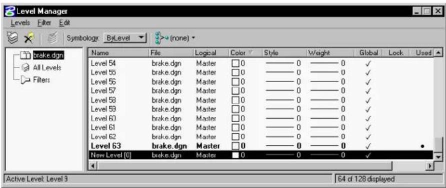
- From the Level Manager dialog box Levels menu, choose New. or
Click the New Level icon.
A new level is created in the level list.
text_image
Level Manager Levels Filter Edit Symbology: ByLevel (none) brake.dgn All Levels Filters Name File Logical Color Style Weight Global Lock Used Level 54 brake.dgn Master 0 0 0 0 ✓ Level 55 brake.dgn Master 0 0 0 0 ✓ Level 56 brake.dgn Master 0 0 0 0 ✓ Level 57 brake.dgn Master 0 0 0 0 ✓ Level 58 brake.dgn Master 0 0 0 0 ✓ Level 59 brake.dgn Master 0 0 0 0 ✓ Level 60 brake.dgn Master 0 0 0 0 ✓ Level 61 brake.dgn Master 0 0 0 0 ✓ Level 62 brake.dgn Master 0 0 0 0 ✓ Level 63 brake.dgn Master 0 0 0 0 ✓ New Level [0] brake.dgn Master 0 0 0 0 ✓ Active Level: Level 3 S4 of 12B displayed- Fill in the new level name.
- Change any of the other attributes by clicking the appropriate column.
- Press Enter.
The new level is created.
Alternative method — To create a new level
- From the Level Manager dialog box, select the master file in which you want to add a level.
- Right-click in the Level list section.
A pop-up menu displays.
| New |
| Set Active |
| Select All |
| Select None |
| Invert Selection |
| Save Filter |
| Delete |
| Rename |
| Properties |
- Choose New.
- Fill in the new level name.
- Press Enter.
The new level is created. - Change any of the other attributes by clicking the appropriate column.
To delete a level
- From the Level Manager dialog box, select the level to be deleted in the level list.
Only levels in the open DGN file can be deleted.
- Press the Delete key.
or
From the Edit menu, click Delete.
or
Right-click and select Delete from the pop-up menu.
To delete all unused level
- In the Level Manager dialog box, from the Edit menu, choose Select All.
or
Right-click in the level list, then choose Select All.
or
Press
- Press the Delete key.
or
From the Edit menu, click Delete.
or
Right-click and select Delete from the pop-up menu.
All unused levels are deleted from the open DGN file.
Used levels remain unchanged.
To delete all unused levels with a key-in
- Key in LEVEL DELETE UNUSED.
To import levels
- From the Level Manager dialog box Levels menu, choose Import.
The Import Level Library dialog opens. This is a standard file selection dialog box.
- Click the Level Library to import.
You can import only ".dgn", ".dgnlib" or ".csv" files.
- Click OK.
The levels in the library are imported into the open DGN file.
To export levels
- From the Level Manager dialog box from the Levels menu, choose Export.
The Export Level Library dialog opens. This is a standard file selection dialog box.
- Enter a Level Library name to export to, or select an existing Level Library to overwrite.
You can export only ".dgn", ".dgnlib" or ".csv" files.
- Click OK.
The levels in the open DGN file are exported to the library. If you entered a new library name, it is given a ".dgnlib" extension.
Modifying level attributes
You can change the properties of a level using the Level Manager dialog box. This includes renaming levels, changing level symbology, and sorting information by column.
To rename a level
-
In the Level Manager dialog box, select the desired level from the level list.
-
From the d ialog box's Edit menu, click Rename. or
Right-click the level list and choose Rename from the pop-up menu.
-
Enter the new level name.
-
Press Enter to change the name.
To control symbology by level
-
From the Level Manager dialog box Level list, select the desired level or range of levels.
-
From the Symbology options menu, select ByLevel.
- Adjust the controls by clicking the desired column.
The Color, Style, and Weight controls are similar to those in the Attributes tool box (see “Setting the Active Element Attributes” on page 2-1).
- Click OK to accept the change.
- Repeat steps 2–3 for each column you wish to change.
To override the display of level symbology
- From the Level Manager dialog box Level list, select the desired level or range of levels.
- From the Symbology options menu, select Overrides.
- Change the desired attributes.
- If Level Symbology is toggled on (Settings > View Attributes), each changed level attribute (color, line weight, or line style) is displayed in place of the elements' own attributes.
If Level Symbology is toggled off (Settings > View Attributes), the attributes will return to their normal state when Symbology is changed back to ByLevel.
- Click OK.
To adjust level properties
- From the Level Manager dialog box Level list, select the desired level.
- From the Edit menu, choose Properties.
The Level Properties dialog box opens. The General tab displays basic file information and symbology information (both ByLevel and Overrides). The Styles tab displays Custom Line Style information (both ByLevel and Overrides).
- Click OK.
To sort levels by column headings
- From the Level Manager dialog box, click the desired heading
to=sort=the=levels=in=ascending=order.
- Click=the desired=heading=again=to=sort=the=levels in=descending=order.
Defining and deleting filters
Filters=are=a=useful=way=to=group=associated=levels=for=the=purposes of=viewing=or=not=viewing=as=a=group.=For=example,=you=might have=a=DGN=file=with=several=hundred=levels.=Within these levels=could=be=filters=for=different=disciplines=such=as=Civil, Architectural,=Mechanical.=Within=Civil=there=might=be=levels=for Civil-Existing,=Civil-Proposed,=Civil-Annotation,=etc.=You=could easily=define=a=filter=called=Civil that=would=show=only=levels=that had=the=word=Civil=as=part/of=the=description.
Filters=can=be=named,=saved,=and=recalled=as=needed=or=defined on-the-fly=for=immediate=one-time=viewing=using=the=Filter=Row in=the=Level=Manager=dialog=box.=Filters=can=be=turned=on=or=off using=the=Level=Display=dialog=box.=Filters=can=be=used=to=turn on—or=off=levels=across=a=model=and=all/of=its=attached-models. Levels=can=be=filtered=by=a-number/of=attributes=such=as=filename, color:=style,=and=line=weight,=to=name=a=few.
Filters=use=different=expression=types=depending=on=the=column in=which=the=expression=is=input.=There=are=three=basic=forms=of expressions:=String,=Integer=and=Boolean.=A=syntax=is=provided=to=filter attributes=with=wildcards=(i.e.,=*,=?)=similar=to=Windows=Explorer search=criteria.=In=addition,=set=based=operations=such=as=|=(or), &=(and)=,=and=-(minus)=have=been=added.=String=Expressions=are applied=on=string=values.=Integer=and=Boolean=values=use=Integer=and Boolean=expressions.=A=short-description=of=each=follows:
- The String Expression format is similar to the format supported in the=MS-Windows=Explorer's=Search=dialog.=In=addition,=set=based operations=such=as=|=(or),=&=(and)=,=and=-(minus)=have=been=added.
• =Integer=Expressions=are=applied=on=integer=numbers.=For example, =1, =10, =15-20. =The=comparison=operators=>, =>=, =<, =<=, and=!==are=also=supported=on=Integer=Expressions.
•=Boolean=Expressions=are=applied=on=check=boxes.=Boolean
Expressions=can=take=a=value=of=0=or=1.
| String=Expressions=Level=Names=that=match=the=criteria |
| lev=All=levels=that=have=the=substring=lev |
| “lev”=The level with h then a me “lev” |
| *1=All=levels=that=end=in=1 |
| lev*=All=levels=that=start=with=the=sub-string=lev |
| 1 | 2 = All=levels=that=have=character=1=or=2 |
| 1 & 2 = All=levels=that=have=characters=1=&=2 |
| 1 - 2 |
| *1=|=*2=|=*3 |
| ((1=|=2)=-=3) |
| “level 1” | “level 2” |

Notice=the=use=of="("=and=")"=to=combine=the=set=operators.

String=expressions=are=valid=for=the=Name,=Description,=File,=and Logical=columns=on=the=Level=Manager=dialog=box.
| Integer Expressions | Level Names that match the criteria |
| 1,10 | Matches levels with numbers 1 or 10. |
| 10, 15–20 | Matches=levels=with=numbers=10, 15, =16, =17, =18, =19, =20. |
| <20 | Matches=all=levels=with=numbers less=than=20. |
| <=20 | Matches=all=levels=with=numbers less=than=or=equal=to=20. |
| >10, <20 | Matches=all=levels=with=numbers greater=than=10=and=less=than=20. |
| >10, <20, !=15 | Matches all levels with numbers greater=than=10=and=less=than=20 and=not=equal=to=15. |

Integer expressions are valid for the Number, Color, Style, Weight and Elements on the Level Manager dialog box.
| Integer Expressions | Level Names that match the criteria |
| 0 | If applied to the used column, matches all levels not used. |
| 1 If applied to the used column, | matches all levels used. |

Boolean expressions are valid for the Global, Lock, Used, and Library on the Level Manager dialog box.

To define a named filter
-
In the Level Manager dialog box, select Filters in the tree view. Existing filters are listed.
-
Click the Create Filter icon. A new filter appears in the filter list.
-
Enter a the name of the new filter in the Filter Name field and press Enter.
-
Click any category and fill in the desired values to define the filter criteria. This defines a named filter.
To define a filter "on-the-fly" using the Level Manager dialog box
- In the Level Manager dialog box, click the List Filter icon.
A list of filters displays.
- Click Untitled.
A blank filter line appears a the top of the filter list.
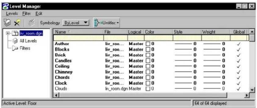
text_image
Level Manager Levels Filter Edit Symbology ByLevel Unlitloc Name File Logical Color Style Weight Global Author liv_roo... Master 0 ——0 ——0 ✓ Blocks liv_roo... Master 0 ——0 ——0 ✓ Brick liv_roo... Master 0 ——0 ——0 ✓ Candles liv_roo... Master 0 ——0 ——0 ✓ Ceiling liv_roo... Master 0 ——0 ——0 ✓ Chimney liv_roo... Master 0 ——0 ——0 ✓ Chords liv_roo... Master 0 ——0 ——0 ✓ Clock liv_roo... Master 0 ——0 ——0 ✓ Clouds liv_room.dgn Master 0 ——0 ——0 ✓ Active Level: Floor 64 of 64 displayed-
Click any category and fill in the desired values to create the filter criteria.
-
Press
on each category to accept the entered value. The filter is defined. You can toggle on/off this filter by clicking the List Filter icon. The filter remains until you exit MicroStation. -
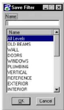
(Optional) — To name and save the filter, from the Levels menu's Filter submenu in the Level Manager dialog box, choose Save As. or Right-click the Level list and choose Save Filter.
The Save Filter dialog box opens.
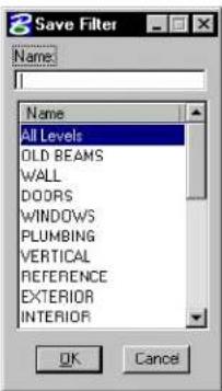
text_image
8 Save Filter Name: All Levels OLD BEAMS WALL DOORS WINDOWS PLUMBING VERTICAL REFERENCE EXTERIOR INTERIOR OK Cancel- (Optional) — Enter the name of the filter to be saved in the Name field.
- (Optional) — Click OK.
The filter is saved.
To define a filter "on the fly" using the Level Display dialog box
- Click the Level Display icon on the Primary Tools tool box.
The Level Display dialog box opens.
- Click the List Filter icon (if necessary) to display filter row. This icon is only active when the Mode is set to Levels.
Level Display dialog box with filter no displayed
text_image
Level Display View: 1 Mode: View Display Target: Flanged/valve.dgn Lntitlec Show Levels Name File Logical Used Body Flange... Master Bolts Flange... Master BOM Flange... Master Bonnet Flange... Master BorderPlot FlangedV... Master Default FlangedV... Master Gate Flange... Master level63 Flange... Master Packing G Flange... Master Seals Flange... Master Seat Flange... Master Stem Flange... Master TitleBlock Flange... Master TitleBlockT FlangedV... Master Wheel Flange... Master-
Enter the desired filter criteria in the appropriate categories.
-
Press Enter on each category to accept the entered value.
This creates a filter on-the-fly. You can toggle this filter on/off by clicking the List Filter icon and selecting none. The filter remains until you exit MicroStation.
To save an on the fly filter to a named filter from Level Display
- Right-click the filter row of the Level Display dialog box.
A pop-up window opens.
- From the Filter submenu, choose Save Filter.
The Save Filter dialog opens.
text_image
Save Filter Name: All Levels OLD BEAMS WALL DOORS WINDOWS PLUMBING VERTICAL REFERENCE EXTERIOR INTERIOR OK Cancel- Enter the name of the filter to be saved in the Name field.
- Click OK.
The filter is saved.
To delete a named filter
- From the Level Manager dialog box, Select the Filters category. A list of filters displays in the filter list.
- Select the filter to be deleted.
- Click the Delete Filter icon. or Right-click in the filter list and choose Delete from the pop-up menu. or From the Edit menu, choose Delete. The filter is deleted from the list.
Showing/Hiding columns of information
You can control the types of information that displays on the Level Manager and Level Display dialog boxes. Columns of information can be toggled on or off from the column headings.
To toggle on/off columns of information
- From the Level Manager dialog box, right-click the column heading row.
A pop-up list of available columns appears. A check mark appears next to columns that are displayed.
- Toggle on/off the columns of information you want to display/hide.
Sharing Level Definitions
A set of level definitions, or level structure, can be stored for shared usage in the level library component of a DGN library, which is simply a special purpose DGN file. See the Administrator Guide for more information on “Designing a Module”.
The manual attachment of libraries is useful when attaching a limited number of libraries to a small number of DGN files. If you need to make a larger number of libraries available to a larger number of DGN files, you can use the MS_DGNLIBLIST configuration variable. This configuration variable allows you to define the path to specific level libraries that MicroStation looks for levels. This eliminates the need to attach each level library to each DGN file.
For more information about level libraries, see "Level Libraries" in the Administrator Guide.
If a Level changes in a Level library, Levels placed in DGN files prior to the change are not automatically updated in the DGN files. To update the DGN file to reflect the changes in the Level library, use the DGNLIB UPDATE LEVELS.
To manually attach a Level Library
- In the Level Manager dialog box, from the Levels menu's Library submenu, choose Attach.
The Attach Level Library dialog box opens.
- Select the level library to attach and click OK.
The levels from the library display at the bottom of the Level List.
To detach a Level Library
- In the Level Manager dialog box, from the Levels menu's Library submenu, choose Detach. The Libraries dialog box opens.
- Select the level library to detach and click OK. The levels from the library are removed from the bottom of the Level List.
To set up the MS\_DGNLIBLIST
- From the Workspace menu, choose Configuration. The Configuration dialog box opens.
- In the Category list box, select Primary Search Paths. Configuration variables which specify default search paths for various type of MicroStation files are listed to the right.
- In that list box, select DGN Library List.
- Click the Edit button. The Edit Configuration Variable dialog box opens.
- Enter the path to the DGN libraries you want available. You can enter multiple paths.
- From the dialog box's File menu, choose Save.
- Click OK to accept the changes.
2
Placing Elements in 2D
In this chapter, you will find procedures concerning basic 2D element placement operations in MicroStation, including:
• Setting the Active Element Attributes (see page 2-1)
• Using Tools in the Linear Elements tool box (see page 2-15)
• Using Tools in the Ellipses tool box (see page 2-35)
• Using Tools in the Polygons tool box (see page 2-43)
• Using Tools in the Points tool box (see page 2-54)
• Using Tools in theArcs tool box (see page 2-66)
• Using the Select Settings Window (see page 2-75)
Setting the Active Element Attributes
When you place an element, the design plane locations of the data points used to draw the element are stored in the design file. In addition, a number of element attributes are stored.
What are element attributes?
Element attributes include the following:
• level (see page 1-1) (in the DGN file on which an element resides)
• color
- line weight
- line style
- fill type and color (for closed elements)
Attributes are determined by settings. For example, while a model's Active Color is set to red, the color attribute of newly placed elements in that model is red. See "Models" in the QuickStart Guide for more information.
Changing an active setting has no effect on previously placed elements. However, you can change any attribute of a previously placed element to the corresponding active setting with the Change Element Attributes tool (see page 4-58).

If you neglect to save settings in the open DGN file before closing it, changes to its models' active element attribute settings will not be in effect the next time you open the file.
Element symbology
These attributes compose what is called element symbology:
• color
- line weight
- line style
- fill color (for closed elements)
Color
MicroStation stores the Active Color and the color attribute of each element as a value in the 0-255 range. To display an element in color, MicroStation looks in the active color table for the color that corresponds to the element color value. You can modify colors in the active color table.
The active color table is depicted graphically in MicroStation as a 16 × 16 palette of colored tiles called a color palette.
You can also change the colors in the active design file by attaching a different color table to it. The attached color table is automatically
activated each time the design file is reopened. Each seed design file supplied with MicroStation has a color table already attached.
Color tables are stored as independent files. The active color table can be saved to a file for future attachment to any design file.
Color can also be set ByCell or ByLevel. If ByCell is selected, when a cell is placed the active color is used in place of the color used when the cell was created. If ByLevel is selected, when an element is placed the active color on the active level is used to display the element.

When working in DWG restriction mode, the DWG color palette is the only color table loaded; no other color tables can be loaded. The menu item Settings > Color Table is disabled. An exception to this is that you can still change the color palette by importing raster files. If you choose to use the color palette of the raster file — that is, you turn off Current Color Palette, the color palette changes.

To set the Active Color from the Attributes tool box
- In the Attributes tool box, press on the colored tile, and drag across the color palette to select the desired color. ^1
Color Palette
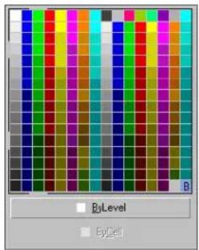
text_image
ByLevel ByCellAlternative method — To set the Active Color
- From the Attributes tool box, choose the Active Color icon. The Color Palette opens.
- Select the desired color from the Color Palette.
The new active color displays on the Attributes tool box.
Alternative method — To set the Active Color
- From the Settings menu, choose Design File.
The DGN File Settings dialog box opens. - In the Category list box, select Element Attributes.
- Select the desired color from the Color field pull-down menu.
The new active color displays on the Attributes tool box.
To set the Active Color with a key-in
- In the Key-in window, key in ACTIVE COLOR
For information about setting the Active Fill Color, see "Fill" on page 2-13.
Line Weight
MicroStation stores the Active Line Weight and the line weight attribute of each element as a value in the 0-31 range.
Line Weight can also be set ByCell or ByLevel. If ByCell is selected, when a cell is placed the active line weight is used in place of the line weight used when the cell was created. If ByLevel is selected, when an element is placed the active line weight on the active level is used to display the element.
To set the Active Line Weight from the Attributes box
- From the Attributes tool box's Line Weight option menu, choose the desired line weight value.
Line Weight option menu
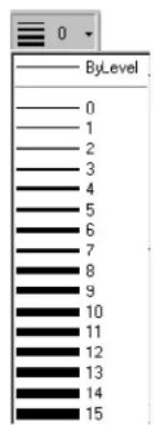
text_image
ByLevel 0 1 2 3 4 5 6 7 8 9 10 11 12 13 14 15Alternative method — To set the Active Line Weight
- From the Settings menu, choose Design File.
The Design File Settings dialog box opens. - In the Category list box, select Element Attributes.
- Select the desired line weight from the Weight field's option menu.
The new active line weight displays on the Attributes tool box.
To set the Active Line Weight with a key-in
- In the Key-in window, key in ACTIVE WEIGHT
Line Style
A line style definition can specify the following:
• A stroke pattern composed of dash strokes and gap strokes of varying lengths.
• Small drawings called point symbols at varying intervals.
Line style definitions are customizable. The default set of line styles in the Line Styles dialog box is intended as a sample. In most cases, line styles should be set up by a site or project manager.
Some of the sample line styles supplied in MicroStation's sample workspaces (not to scale)
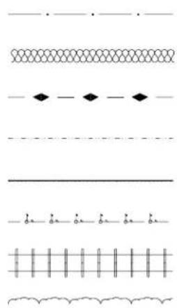
natural_image
Pure electrical circuit lines without any symbolsLine style modifiers
Line style modifiers or overrides allow some characteristics of a line style to be modified as elements are placed without requiring separate line style definitions.
Modifiers are available for the following stroke pattern and stroke attributes:
- Origin and end widths. These modifiers are applied to each stroke and can be used to create wide or tapered elements.
- Stroke pattern shift.
In addition, a Scale Factor modifier is available. This modifier is applied to all length values in the line style definition.
Line Style can also be set ByCell or ByLevel. If ByCell is selected, when a cell is placed the active line style is used in place of the line style used when the cell was created. If ByLevel is selected, when an element is placed the active line style on the active level is used to display the element.
General Procedure — To use a custom line style
- Set the Active Line Style. See "To set the Active Line Style" on page 2-9.
- Activate any desired line style modifiers. See "Activating line style modifiers" on page 2-9.
- Place elements with the Active Line Style and any active modifiers.
To set the Active Line Style
- From the Attributes tool box's Line Style option menu, choose the desired line style. ^2
Line Styles option menu

text_image
ByLevel 0 1 2 3 4 5 6 7 (Border) (Center) (Dashdot) (Dashed) (Divide) (Dot) (Hidden)Alternative method — To set the Active Line Style
- From the Element menu's Line Style, choose Custom.
The Line Styles dialog box opens.
text_image
Line Styles Names { Offset Lines } { Origin Line } { Rail Foad } { Tapered Dash } { Tree Line } { Wide Dash } Width Origin: 0.0000 End: 0.0000 Scale factor: 0.00000 Shift: None ...\\Program Files\\Bentley\\work.space\\system\\symbol\\style.rsc Click to Activate (Wide Dash - Stroke)- In the Names list box on the Line Styles dialog box, double-click the name of the desired line style.
or In the Names list box on the Line Styles dialog box, select the name of the desired line style, and click the large button at the bottom of the dialog box on which a sample of the selected line style is displayed. (To make the large button visible, you must first turn on the Show Details check box.)
Alternative method — To set the Active Line Style with a key-in
- In the Key-in window, key in ACTIVE STYLE
Activating line style modifiers
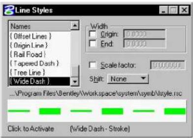
Line style modifiers are activated in the Line Styles dialog box. The large button in the dialog box shows the line style selected in the list box with active modifiers applied. (To make the large button visible, you must first turn on the Show Details check box.)
The New User interface does not let you activate line style modifiers.
To override the starting or ending width for each dash stroke in elements placed with the Active Line Style
-
From the Element menu's Line Style, choose Custom. The Line Styles dialog box opens.
-
(Optional) — To set the start width, turn on Origin, and key in the desired width in master units in the Origin field.
-
(Optional) — To set the ending width, turn on End, and key in the desired width in master units in the End field.
Line Styles setting box with Show Details on
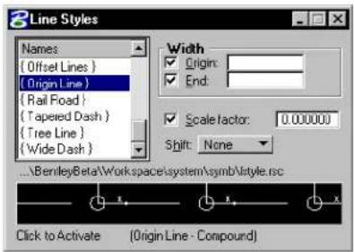
text_image
8Line Styles Names { Offset Lines } { Origin Line } { Rail Foad } { Taped Dash } { Tree Line } { Wide Dash } Width ✓ Origin: ✓ End: ✓ Scale factor: 0.000000 Shift: None ...BemileyBeta\Workspace\system\symb\style.rc Click to Activate (Origin Line - Compound)To apply a scale factor to all displayable characteristics of the Active Line Style
- From the Element menu's Line Style, choose Custom.
The Line Styles dialog box opens.
- Turn on Scale Factor, and key in the desired scale factor in the Scale Factor field.
To shift or adjust stroke patterns differently than specified in the Active Line Style definition
- From the Element menu's Line Style, choose Custom.
The Line Styles dialog box opens.
- To shift stroke patterns relative to the beginning of elements or element segments, choose Distance from the Shift option menu, and key in the shift distance in master units in the Distance field. or
To adjust stroke patterns such that a fraction of the first strokes in stroke patterns are displayed at the start and end of elements or element segments, choose Fraction from the Shift option menu, and key in the fraction in decimals in the Fraction field.

While the Change Element Attributes (see page 4-58) tool is used to adjust the line style modifiers of an existing element as a set, the Modify Line Style Attributes (see page 4-64) tool in the Change Attributes tool box can be used to adjust individual line style modifiers.
Standard line styles
Standard line styles (also known as line codes), numbered 0-7, are based on output device coordinates, and therefore are not truly WYSI WYG ("what-you-see-is-what-you-get"), as are custom line styles. Hence, it is recommended that you use custom line styles instead of standard line styles.

Line Styles 1–7 are disabled if DWG Restriction mode is in operation. Only custom line styles are active in this mode.
Level symbology
Each element in a design file has its own symbology. To make it clearer which elements are on a particular level, you can define an alternative symbology for all elements on a level. You can then display the elements with their “normal” symbology or with the level symbology.
To copy a level from another design file
- From the Settings menu's Level submenu, choose Manager. or
Click the Active Level field on the Status bar.
The Level Manager dialog box opens.
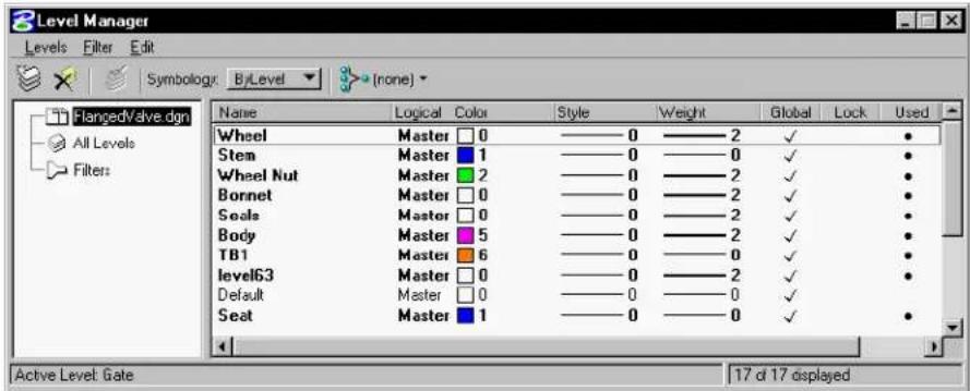
text_image
Level Manager Levels Filter Edit Symbology: ByLevel (none) FlangedValve.dgn All Levels Filters Name Logical Color Style Weight Global Lock Used Wheel Master 0 ———0———2 ✓ ● Stem Master 1 ———0———0 ✓ ● Wheel Nut Master 2 ———0———2 ✓ ● Bonnet Master 0 ———0———2 ✓ ● Seals Master 0 ———0———2 ✓ ● Body Master 5 ———0———2 ✓ ● TB1 Master 6 ———0———0 ✓ ● level63 Master 0 ———0———2 ✓ ● Default Master 0 ———0———0 ✓ ● Seat Master 1 ———0———0 ✓ ● Active Level: Gate 17 d 17 displayed- From the File menu, choose Import.
The Import Level dialog box opens.
-
Select the design file from which you want to copy the level symbology definition.
-
Click the OK button.
The list box in the Symbology tab page updates to show the copied definition.
To define level symbology "from scratch"
-
From the Settings menu's Level submenu, choose Manager.
-
For each attribute (color, [numbered] line style, or line weight) to be set, right-click in the attribute column.
The appropriate selection dialog box opens.
- Adjust the desired controls.
The Color, Style, and Weight controls are similar to those in the Element Attributes dialog box. For information about using those controls, see "To set the Active Color" on page 2-4 and "To set the Active Line Weight" on page 2-5.
To display elements using level symbology
- From the Settings menu, choose View Attributes (or press
). or
From any view window's control menu, choose View Attributes.
The View Attributes dialog box opens.
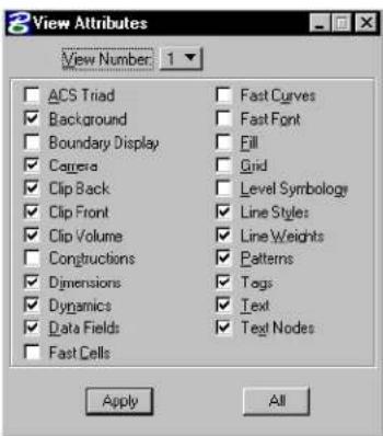
text_image
View Attributes View Number: 1 ACS Triad Background Boundary Display Camera Clip Back Clip Front Clip Volume Constructions Dimensions Dynamics Data Fields Fast Cells Fast Curves Fast Font Fill Grid Level Symbology Line Styles Line Weights Patterns Tags Text Text Nodes Apply All-
Turn on the Level Symbology attribute.
-
Click Apply or All.
Other element attributes
In addition to level, color, line weight, and line style, elements have these attributes:
- Fill (none, opaque, or outline)
• Class (primary or construction) - The area attribute determines whether a closed element is a solid or a hole (see "Putting Holes in Solid Elements" on page 7-5).
Fill
The fill attribute applies only to closed elements such as circles, ellipses, and polygons. Closed elements completely enclose the area within their boundaries.
Top: Opaque fill; Bottom: Outline fill


By default, a closed element is displayed in a wireframe view by lines in the Active Color that outline the area occupied by the element. The area of the element inside the outline is transparent.
A closed element is filled when the area within its outline is displayed as a solid area of color. The color is determined by the Active Fill Color. When an element is opaque, it is displayed as a solid shape of the Active Color. In that case, the lines outlining the element are not discernible since the "fill" has the same color.

In any view, opaque and filled elements are displayed as outlines unless the Fill view attribute is on for that view. In other words, turning off Fill in a view hides the “fill.”
The effects of the fill attribute and the Fill view attribute are summarized in this table:
| Fill Type Fill | on Fill off | |
| None No fill displayed | No fill | displayed |
| Opaque Element | filled with color of the element | No fill displayed |
| Outline Element | filled with Active Fill Color | No fill displayed |

A series of lines or a closed line string can also enclose an area. However, MicroStation treats neither as a shape. Therefore, neither can be assigned an area or fill attribute.

To set the Active Fill Type and Color
- Select a tool in the Polygons tool box.
- From the Fill Type option menu in the Tool Settings window, choose None, Opaque, or Outline.
- Select the desired color from the Fill Color color palette.

To turn Fill on or off in a view
-
From the Settings menu, choose View Attributes (or press
). or From any view window's control menu, choose View Attributes. The View Attributes dialog box opens. -
From the View option menu in the settings box, choose the desired view.
- Click the Fill check box.
- Click Apply or All.

To change the fill type and color of an element, use the Change Element to Active Fill Type tool (see page 4-63) in the Change Attributes tool box.
Class
By convention, elements with the class attribute of Construction are used as drawing aids. For example, you might place a construction element in a particular location as an element to “snap” other elements to, but you would not plot the construction element when the design is complete. The elements that are actually part of the design usually have the class attribute of Primary.
To set the Active Class
- From the Settings menu, choose Design File.
The Design File Settings dialog box opens.
-
In the Category list box, select Element Attributes.
-
From the Class option menu, choose Primary or Construction.
-
Click the OK button.
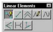
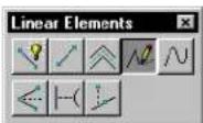
Linear Elements tool box
The tools in the Linear Elements tool box are used to place linear elements.
1 Point curves are the traditional MicroStation curve element type (9). Stream curves are used primarily for tracing images when digitizing.
| To | Select in the Linear Elements tool box |
| Place a line, line string, shape, arc, or circle or a combination thereof as a complex element. |  PlaceSmartLine(see page 2-17) PlaceSmartLine(see page 2-17) |
| Place or construct a line. |  PlaceLine(see page 2-23) PlaceLine(see page 2-23) |
| Place a multi-line. | [xwc6]Place Multi-line (see page 2-24) |
| Place a stream line string (primarily for tracing images when digitizing). |  Place Stream i.e. String (see page 2-27) Place Stream i.e. String (see page 2-27) |
| Place a point curve or a stream curve. ^1 |  Place Point or Stream Curve (see page 2-29) Place Point or Stream Curve (see page 2-29) |
| Construct a line that bisects an angle. |  Construct Angle Bisector (see page 2-31) Construct Angle Bisector (see page 2-31) |
| Construct a line between two elements at their closest points. |  Construct Minimum Distance Line (see page 2-32) Construct Minimum Distance Line (see page 2-32) |
| Construct a line at Active Angle | [wxzz]Construct Line a t Acti (see page 2-33) |
Key-in: DIALOG TOOLBOX LINEAR [OFF | ON | TOGGLE]
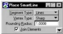
Place SmartLine

Used to place a chain of connected line segments and arc segments as individual elements or as a single line string, shape, circle, complex chain, or complex shape element. This tool supports all snap modes. See “Snapping to tentative points on elements” on page 3-4 for information on snap modes.
Rounded vertices can be created by allowing the tool to automatically place an arc tangent to two adjacent line segments. You can also round between two arc segments, or between an arc segment and a line segment. If a rounded vertex cannot be created, a sharp one is created instead. (This is often a more convenient, though less versatile, way of placing an arc than directly drawing one as a segment.)
| Tool Setting | Effect |
| Segment Type | S e t s t h e t y p e o f s e g m e n t. Lines—Sets line segments. Arcs—Sets arc segments. |
| Vertex Type | Sets the type of vertex.· Sharp· Rounded· ChamferedIf after snapping to the first vertex point and before accepting it, you change Vertex Type, the new setting applies only to the final vertex.(For information about snapping, see “Tentative snap points” on page 3-3.) |
| Round-ing Radius | (with Vertex Type set to Rounded) If on, sets the arc radius for a rounded vertex. If after snapping to the first vertex point and before accepting it, you change Round Radius, the new setting applies only to the final radius. |
| Chamfer Offset | (with Vertex Type set to Chamfered) Sets the two distances required to define a chamfer. Chamfer Offset requires that the two chamfer distances be equal (from the theoretical intersection point). |
| Join Elements | If off, places segments as individual elements and also · eliminat es the option to close the chain (Closed Element) upon snapping to the first vertex point. · allows individual segments to have different symbologies.Toggling this setting affects previously defined segments in the chain. |
| Closed Element | If on, accepting a tentative point snapped to the first vertex point closes the element. Otherwise, accepting such a tentative point does not close the element. |
| Area (with | Closed Element on) Sets the Active Area — Solid or Hole |
| Fill Type | (with Closed Element on) Sets the Active Fill Type• None (no fill)• Opaque (filled with Active Color)• Outlined (filled with Fill Color) |
| Fill Color | (with Closed Element on) Sets the color with which the element is filled:• If Fill Type is Opaque, the fill color is the Active Color.• If Fill Type is Outlined, the fill color can be different from the Active Color. |
| Rotate AccuDraw to segments | (in SmartLine Placement Settings) If on, after you enter line segments, AccuDraw typically rotates its compass such that the x-axis aligns with the line that you just placed. Instead of turning off AccuDraw's “context sensitivity” feature which would stop this aligning behavior in all the tools, the Rotate AccuDraw to segments setting affects only the Place SmartLine tool. |
| Always start in line mode | (in SmartLine Placement Settings) If on, when you select the Place SmartLine tool, the segment type normally defaults to “Lines,” despite the last segment type used. If off, AccuDraw uses the last segment type that you used. |
To place a chain of connected line segments and arc segments
- Select the Place SmartLine tool.
- From the Segment Type option menu, choose the segment type.
-
If this is the first segment, enter a data point to position the first vertex.
-
Enter data points to define the segment (follow the prompts in the status bar), snapping if necessary to previously defined segments. For information about snapping, see "Tentative snap points" on page 3-3.
| Segment Type | Enter data points to S | Similar to |
| Lines Define | endpoints of segments. | None |
| Arcs Define | cente r.Define sweep angle. ^2 | Place Arc (see page 2-67) |
2 To change the direction of an arc — from counterclockwise to clockwise, for example — swing the pointer around in the desired direction.
-
To define another segment of the same type, return to step
-
If you snap to the first segment that are not completing a shape or complex shape, turn off Closed Element before accepting the tentative point.
or
To choose a different type of segment, return to step 2.
or
To complete a line, line string, arc, or complex chain, Reset.
or
To complete a shape, circle, or complex shape, snap to the first vertex point, and accept the tentative point.
text_image
1 2A
text_image
1 2B
text_image
1 2C
text_image
5×E
text_image
4 3D
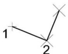
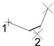
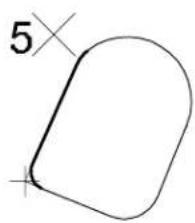
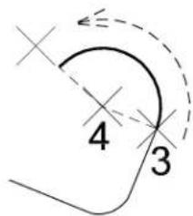
The following table explains illustrations of the Place SmartLine tool starting at the top left and moving clockwise.
| A | Constructing a line string by setting Segment Type to Lines, Vertex Type to Sharp, and entering data points 1 and 2. |
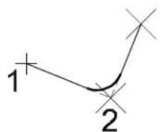
| B | Setting Vertex Type to Rounded and Rounding Radius to 3.00 causes the active vertex (at the location of data point 2) to be rounded with an arc. (If the data points entered do not allow a round of the specified radius, a sharp vertex is created. Only one vertex at a time is affected by the vertex settings.) |
| C | Setting Vertex Type to Chamfered and Chamfer Offset to 3.00. |
| D | After setting Vertex Type back to Rounded and entering data point 3, Segment Type is set to Arcs, and data point 4 is entered to define the arc center. The direction of the arc (clockwise or counterclockwise) is determined by swinging the pointer past the starting point. (The Vertex Type setting is disregarded.) |
E After entering data point 5 to complete the arc segment, setting Segment Type back to Lines and snapping a tentative point to the starting point tentatively closes the element. To continue without closing the element, turn off Close Element prior to accepting the tentative point. (While the tentative point is active it is possible to change the vertex settings of the final vertex without affecting other vertices — here they are set to Rounded and 1.50. It is also possible to turn on Fill and change other tool settings related to closed elements while the tentative point is active.)
Key-in: PLACE SMARTLINE

To choose SmartLine Placement Settings, click the arrow in the lower right corner of the tool settings window.
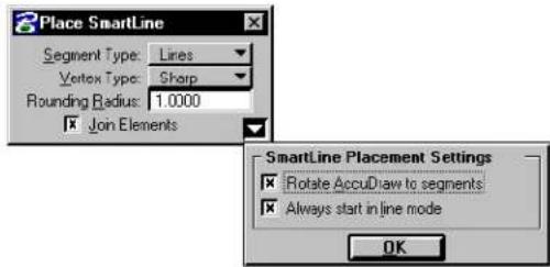
text_image
Place SmartLine Segment Type: Lines Vertex Type: Sharp Rounding Radius: 1.0000 Join Elements SmartLine Placement Settings Rotate AccuDraw to segments Always start in line mode OK
Place SmartLine is designed to be used with the versatile drafting aid, AccuDraw. See "AccuDraw and the Place SmartLine Tool" on page 3-70.

To negate the last data point — before Resetting (or otherwise completing the placement procedure) — without affecting previously defined segments, choose Undo from the Edit menu. (Choosing Undo after completing the procedure negates the entire chain.)

To combine contiguous open elements of any type into a complex chain (open) or complex shape (closed), use the Create Complex Chain tool (see page 7-12) or Create Complex Shape tool (see page 7-15) in the Groups tool box. (With Join Elements turned on, Place SmartLine automatically places multiple segments defined with it as a single element.)
Place Line

Used to place or construct a line.
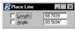
| Tool Setting | Effect |
| Length | If on, sets the length in working units. |
| (Active) Angle | If on, constrains the line to the Active Angle, which can be keyed in here as well. |
To place a line
- Select the Place Line tool.
- Enter a data point to define one endpoint.
- If necessary, enter a data point to define the other endpoint.
Place Line. Clockwise from top left: Unconstained, with Length "L" constrained, with Angle "AA" constrained, with both Length and Angle constrained.
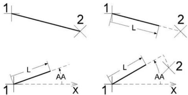
Key-in: PLACE LINE [CONSTRAINED | ANGLE]
Place Multi-line

Used to place a planar multi-line. The active multi-line definition is set in the Multi-lines settings box, which is opened by choosing Multi-lines from the Element menu.
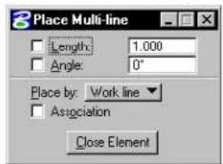
text_image
Place Multi-line Length: 1.000 Angle: 0° Place by: Work line Association Close Element2-24 MicroStation User Guide
| Place By | Then the work line is | Illustration |
| Work Line A | offset position 0,0 as defined in the active multi-line definition (in the illustrations, the position of the dashed line). | 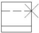 |
| Center Adjusted to be midway between the outermost component lines. If there is a component line at the center, the work line is superimposed on it. | 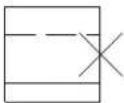 | |
| Maximum Adjusted to be superimposed on the component line with the maximum Offset.1 | 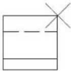 | |
| Minimum Adjusted to be superimposed on the component line with the minimum Offset.a | 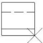 | |
1 Illustrations show pointer when drawing from left to right. Thus, the top component line has a positive Offset, and the bottom two component lines have negative Offsets.
| Tool Setting | Effect |
| Length | If on, sets segment length, in working units. |
| (Active) Angle | If on, constrains the multi-line to the Active Angle, which can be keyed in here as well. |
| Place By | Sets the work line's position in the multi-line when placed and how the component lines are offset (see table above). The work line's position can be changed between placements of individual segments. Placing a multi-line in this manner, however, prevents you from using Association Lock to associate vertices with other elements. ^1 |
| Association Lock | If on, and Snap Lock (see page 3-4) is on, any vertex in a multi-line can be associated to another element by snapping to that element. (For information about snapping, see “Tentative snap points” on page 3-3.) |
When a multi-line in the design is selected, the handles are placed on the work line. If the Match All Element Settings tool in the Change Attributes tool box is used to make the active multi-line definition match that of the multi-line in the design, the work line is assigned the offset 0,0.
To pplacea anunti-lbine
-
Select the Place Multi-line tool.
-
Enter a data point to define the beginning of the multi-line.
-
Continue entering data points to define other vertices.
-
To complete an open multiline, Reset.
or To complete a closed multi-line, click the Close Element button or key in CLOSE ELEMENT.
In the latter case, the multi-line is closed at the location of the first vertex, and this vertex has a corner joint.
text_image
1 2 3 4 1 2 3 4Place Multi-line. Left: Resetting after entering data point 4 to complete an open multi-line. Right: Clicking the Close Element button after entering data point 4 to complete a closed multi-line.
Key-in: PLACE MLINE CONSTRAINED
To change a multi-line's attributes to the active multi-line definition, use the Change Multi-line to Active Definition tool (see page 4-67) in the Change Attributes tool box.
The Multi-line Joints tool box (see page 7-32) contains specialized tools for working with multi-lines.
Place Stream Line String

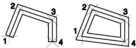
Used to place a stream line string — primarily for tracing images when Digitizing (see page 7-144). Many vertices can be defined without having to enter a large number of individual data points. The movement of the pointer is sampled, and data points are recorded based on the tool settings.
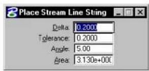
text_image
Place Stream Line String Delta: 0.2000 Tolerance: 0.2000 Angle: 5.00 Area: 3.130e+000| Tool Setting | Effect |
| Delta Sets the minimum distance, in working units, between sampled points. | |
| To le r -ance | Sets the maximum distance, in working units, between recorded data points. |
| Angle Sets the angle, in degrees, that when exceeded, causes the last sampled point to be recorded as a data point. | |
| Area | Sets the area that, when exceeded, causes a sampled point to be recorded as a data point. |
To place a stream line string
-
Select the Place Stream Line String tool.
-
Enter a data point to define the origin.
-
Move the pointer. A stream of data points is entered without pressing the Data button.
-
Reset to end the line string.
Key-in: PLACE LSTRING STREAM
A line string element can have a maximum of 5000 vertices. If more than 5000 vertices are defined, a complex chain consisting of one or more line string elements is created.
The tool settings can also be set in the DGN File Settings box (Settings menu > Design File...), in the Stream category.
To place a stream curve, use the Place Point or Stream Curve tool (see page 2-29).
Place Point or Stream Curve

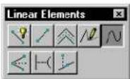
Used to place a point or stream curve.
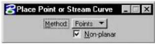
| Tool Setting | Effect |
| Method | Sets how the curve is defined.Point—Traditional MicroStation curve: “Flat” between the first and second and next-to-last and last data points entered. In many cases, B-splines are more accurate and easier to manipulate.Stream—Primarily for tracing images when digitizing. Many vertices can be defined without having to enter a large number of individual data points. The movement of the tablet cursor is sampled and data points are recorded based on the Active Stream Delta, Tolerance, Angle, and Area. |
| Non-planar | If on and Method is set to Point, a space curve can be placed (the active design must be 3D). |
| Delta | If Method is Stream, sets the minimum distance, in working units, between sampled points. |
| To le r -ance | If Method is Stream, sets the maximum distance, in working units, between recorded data points. |
| Angle | If Method is Stream, sets the angle, in degrees, that when exceeded, causes the last sampled point to be recorded as a data point. |
| Area If Method is Stream, sets the area that, when exceeded, causes a sampled point to be recorded as a data point. | |
To place a point curve
- Select the Place Point or Stream Curve tool.
- In the tool settings window, set Method to Point.
- Enter a data point to define the curve's beginning.
- Enter a second data point for the first curve segment.
- Enter a data point to complete the first curve segment.
- Enter additional data points to add segments to the curve.
- Reset to end the curve.
Placing a point curve
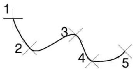
text_image
1 2 3 4 5To place a stream curve
- Select the Place Point or Stream Curve tool.
- In the tool settings window, set Method to Stream.
- Enter a data point to define the origin.
- Move the pointer. A stream of data points is entered without pressing the Data button.
- Reset to end the curve.
Key-in: PLACE CURVE [ICON|POINT|STREAM]

A curve element can have 3 to 97 vertices. If more than 97 vertices are defined, a complex chain consisting of one or more curve elements is created.

The tool settings Delta, Tolerance, Angle, and Area can also be set in the Design File Settings dialog box (Settings > Design File...), in the Stream category.

To place a stream line string, use the Place Stream Line String tool (see page 2-27).
Construct Angle Bisector

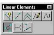
Used to construct a line that bisects an angle defined by three data points.
To construct an angle bisector
- Select the Construct Angle Bisector tool.
- Enter a data point to define one endpoint of the angle that is to be bisected.
- Enter a second data point to define the vertex of the angle.
- Enter a third data point to define the second endpoint of the angle.
Construct Angle Bisector
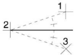
text_image
1 2 3Key-in: CONSTRUCT BISECTOR ANGLE
Construct Minimum Distance Line

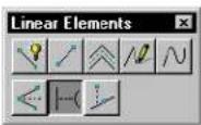
Used to construct a line between two elements at their closest points.
To construct a minimum distance line
- Select the Construct Minimum Distance Line tool.
- Enter a data point to identify the first element. See "Identifying elements" on page 3-2.
- Enter a data point to identify the second element.
- Accept the line.
Construct Minimum Distance Line
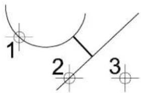
text_image
1 2 3Key-in: CONSTRUCT LINE MINIMUM
Construct Line at Active Angle

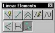
Used to construct a line that intersects a line segment (line or segment of a line string or shape) at the Active Angle.

| Tool Setting | Effect |
| Method | Sets when the intersection is defined.From Point—The intersection is defined when the element being intersected is identified (see step 2 below).To Point—The intersection is defined by the second data point (see step 3 below). |
| Active Angle | Sets the angle, measured counter-clockwise from the intersected line segment, at which the line is constructed. |
| Length | If on, the length is constrained to the value that is keyed in the field. |
To construct a line that intersects a line segment at the Active Angle
- Select the Construct Line at Active Angle tool.
- Identify the element to intersect.
If the Method is From Point, this data point defines the intersection.
- Enter a data point.
If Length is off, this data point defines the length.
If the Method is To Point, this data point defines the intersection.
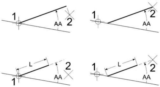
Construct Line at Active Angle ("AA" denotes the Active Angle). Top Left: Method: From Point Length not constrained. Top Right: Method: To Point Length not constrained. Bottom Left: Method: From Point Length constrained. Bottom Right: Method: To Point Length constrained.
Key-in: CONSTRUCT LINE AA [1 | 2 | 3 | 4]
Ellipses tool box
The tools in the Ellipses tool box are used to place ellipses (including circles).
| To | Select in the Ellipses tool box |
| Place a circle. |  Place Circle (see page 2-36) Place Circle (see page 2-36) |
| Place an ellipse, precisely positioning the center and one end of the primary axis. |  Place Ellipse (see page 2-39) Place Ellipse (see page 2-39) |
Key-in: DIALOG TOOLBOX ELLIPSES [OFF | ON | TOGGLE]
Place Circle


Used to place a circle.
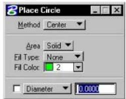
text_image
Place Circle Method Center Area Solid Fill Type: None Fill Color: 2 Diameter 0.0000| Tool Setting | Effect |
| Method | Sets the method by which the circle is placed.Center—position by center.Edge—position by three data points on the circumference.Diameter—position by diameter's endpoints. |
| Area Active Area — Solid or Hole. | |
| Fill Type | Active Fill Type — None (no fill), Opaque (filled with Active Color), or Outlined (filled with Fill Color). |
| Fill Color | Sets the color with which the circle is filled.If Fill Type is Opaque, the Active Color.If Fill Type is Outlined, the fill color can be different from the Active Color. |
| Diameter | If on, sets the diameter, in working units (if Method is set to Center or Edge). To instead set the radius, choose Radius from the adjacent option menu. |
To place a circle by its center
- Select the Place Circle tool.
- In the tool settings window, set Method to Center.
- Enter a data point to define the center.
- If Diameter (or Radius) is off, enter a data point to define the radius.
Place Circle, with Method set to Center. Left: Diameter on; Right: Diameter off.
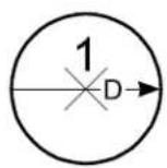
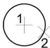
To place a circle by defining three points on its circumference
- Select the Place Circle tool.
- In the tool settings window, set Method to Edge.
- Enter a data point on the circumference.
- Enter a second data point on the circumference. ^3
- If Diameter (or Radius) is off, enter a third data point on the circumference.
Place Circle, with Method set to Edge. Left: Diameter on; Right: Diameter off.
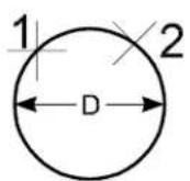
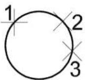
To place a circle by its diameter
- Select the Place Circle tool.
- In the tool settings window, set Method to Diameter.
- Enter a data point to define one endpoint of a diameter.
- Enter a second data point to define the other endpoint of the diameter.
Place Circle, with Method set to Diameter.
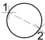
Key-in: PLACE CIRCLE ICON
Key-in: PLACE CIRCLE
Place Ellipse


Used to place an ellipse.
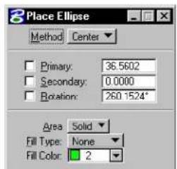
text_image
Place Ellipse Method Center Primary: 36.5602 Secondary: 0.0000 Rotation: 260.1524* Area Solid Fill Type: None Fill Color: 21 If both Primary and Secondary are on, the primary and secondary axes are parallel to the view x- and y-axes, respectively.
| Tool Setting | Effect |
| Method | Sets the method by which the ellipse is placed. Center—position by the center and one end of the primary axis. Edge—position by both ends of the primary axis. |
| Primary | If on, sets the primary axis radius.1 |
| Secondary | If on, sets the secondary axis radius. |
| Rotation | If on, sets the rotation of the primary axis relative to the view x-axis. |
| Area Sets | Active Area — Solid or Hole. |
| Fill Type | Active Fill Type — None (no fill), Opaque (filled with Active Color), or Outlined (filled with Fill Color). |
| Fill Color | Sets the color with which the ellipse is filled.If Fill Type is Opaque, the fill color is the Active Color.If Fill Type is Outlined, the fill color can be different from the Active Color. |
To place an alliplies by centered edge
- Select the Place Ellipse tool.
- In the tool settings window, set Method to Center.
- Enter a data point to define the center.
If Primary, Secondary, and Rotation are on, the ellipse is placed.
- If necessary, enter a data point.
| Constraints on | Data point defines the following |
| None | Ellipse rotation and primary axis radius |
| Rotation | Primary axis radius |
| Primary | Secondary axis radius |
- If necessary, enter a third data point.
If Secondary is off, it defines the secondary axis radius.
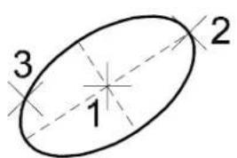
text_image
3 1 2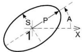
text_image
S P A 1 XPlace Ellipse, with Method set to Center. Left: All constraints off. Right: All constraints on. Primary axis denoted by "P." Secondary axis denoted by "S." Rotation angle denoted by "A."
▶ Toplaceanellipsebyedgepoints
- Select the Place Ellipse tool.
- In the tool settings window, set Method to Edge.
-
Enter a data point to define one end of the primary axis.
If Primary, Secondary, and Rotation are on, the ellipse is placed. -
If necessary, enter a second data point to define another point on the ellipse.
If either combination of constraints is on, the ellipse is placed:
— Primary or Secondary, and Rotation
— Primary and Secondary
If the pointer is moved to a point that cannot be on an ellipse that includes the points defined in steps 3 or 4, the dynamics disappear.
- If necessary, enter a third data point to define the other end of the primary axis.
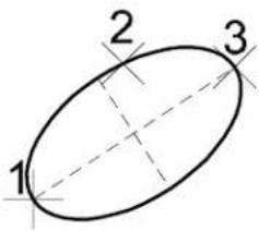
text_image
1 2 3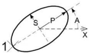
text_image
S P A X 1Place Ellipse, with Method set to Edge. Left: All constraints off; Data points 1, 2, and 3 must be entered clockwise. Right: All constraints on. Primary axis, denoted by "P." Secondary axis, denoted by "S." Rotation angle, denoted by "A."
Key-in: PLACE ELLIPSE ICON
Key-in: PLACE ELLIPSE
Polygons tool box
The tools in the Polygons tool box are used to place planar polygonal shapes.
| To | Select in the Polygons tool box |
| Place a rectangular shape. |  Place Block (see page 2-44) Place Block (see page 2-44) |
| Place a polygonal shape. |  Place Shape (see page 2-46) Place Shape (see page 2-46) |
| Place a sh ap e w i t h e a c h s e g m perpendicular or parallel to all other segments in the shape. |  Place Orthogonal Shape (see page 2-48) Place Orthogonal Shape (see page 2-48) |
| Place a regular polygon (one with all sides and angles the same). |  Place Reguln Polygon (see page 2-50) Place Reguln Polygon (see page 2-50) |
Key-in: DIALOG TOOLBOX POLYGONS [OFF | ON | TOGGLE]

Rectangular solids can be drawn in 3D with the Place Slab tool (see page 8-83), or can be generated from a planar closed element with the Extrude tool (see page 8-101).
Place Block

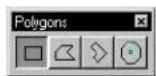
Usedtoplaceablock(rectangularshape).
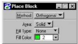
| Tool Setting | Effect |
| Method | Sets how the block's orientation is determined.Orthogonal—Block is orthogonal to the view in which the first data point is entered.Rotated—Orientation is defined with a data point (step 3). |
| Area | Active Area — Solid or Hole. |
| Fill Type | Active Fill Type — None (no fill), Opaque (filled with Active Color), or Outlined (filled with Fill Color). |
| Fill Color | Sets the color with which the block is filled.If Fill Type is Opaque, the Active Color.If Fill Type is Outlined, the fill color can be different from the Active Color. |
To place a rectangular shape
- Select the Place Block tool.
- Enter a data point to define one corner.
- If Method is set to Rotated, enter a data point to define the orientation.
- Enter a data point to define the corner that is diagonal from the first.
Place Block. Left: Method set to Orthogonal; Right: Method set to Rotated.
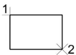
text_image
1 2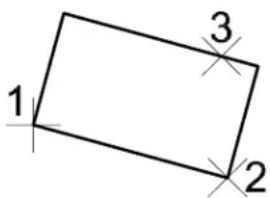
text_image
1 2 3Key-in: PLACE BLOCK ICON
Key-in: PLACE BLOCK [ORTHOGONAL | ROTATED]

In 3D, if the second data point is placed at a different depth than the first point, the block is rotated about the x-axis of the view such that the diagonal corner is placed at the second data point. In other words, the first data point defines the depth for one horizontal segment of the block and the second data point defines the depth for the opposite segment.

MicroStation does not have a "Place Square" tool. However, any of these methods can be used to place a square:
- Use the Place SmartLine tool (see page 2-17) and AccuDraw. See "AccuDraw and the Place SmartLine Tool" on page 3-70.
• Use the Place Block tool (see page 2-44) and AccuDraw.
• Use the Place Regular Polygon tool (see page 2-50) with the number of edges set to 4.
Place Shape

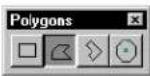
Used to place a polygonal shape by entering a series of data points to define the vertices.
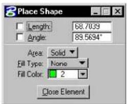
text_image
Place Shape Length: 68.7039 Angle: 89.5694° Area: Solid Fill Type: None Fill Color: 2 Close Element| Tool Setting | Effect |
| Length | If on, sets segment length, in working units. |
| (Active) Angle | If on, constrains sides to the Active Angle, which can be keyed in. |
| Area Active | Area — Solid or Hole. |
| Fill Type | Active Fill Type — None (no fill), Opaque (filled with Active Color), or Outlined (filled with Fill Color). |
| Fill Color | Sets the color with which the shape is filled.• If Fill Type is Opaque, the Active Color.• If ill Type is Outlined, the fill color can be different from the Active Color. |
| Close Element | Closes a shape by connecting the first point with the last point. |
To place a polygonal shape
- Select the Place Shape tool.
- Enter a data point to define the first vertex.
-
Continue entering data points to define the other vertices.
-
To close the shape, enter a data point at the location of the first vertex.
or Click the Close Element button. or Key in CLOSE ELEMENT.
Place Shape
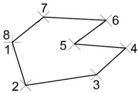
text_image
7 6 5 4 3 2 1 8Key-in: PLACE SHAPE CONSTRAINED
√ The Place SmartLine tool (see page 2-17) in the Linear Elements tool box, particularly when used in conjunction with AccuDraw, affords more flexibility for placing polygonal shapes than Place Shape. See “AccuDraw and the Place SmartLine Tool” on page 3-70.
A shape element can have 3 to 100 vertices. To place a complex shape with over 100 vertices, use the Place SmartLine tool (see page 2-17) in the Linear Elements tool box.
In 3D, the Place Shape tool forces the shape vertices to be planar. If non-planar data points are entered, the vertices of the shape are forced
to a plane defined by the first three non-colinear vertices.
Place Orthogonal Shape

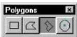
Used to place a non-rectangular shape in which each segment is either perpendicular or parallel to all other segments.
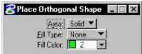
| Tool Setting | Effect |
| Area Active Area — Solid or Hole. | |
| Fill Type | Active Fill Type — None (no fill), Opaque (filled with Active Color (see page 2-2)), or Outlined (filled with Fill Color). |
| Fill Color | Sets the color with which the shape is filled.· If Fill Type is Opaque, the Active Color.· If Fill Type is Outlined, the fill color can be different from the Active Color. |
To place an orthogonal shape
- Select the Place Orthogonal Shape tool.
- Enter a data point to define the first vertex.
- Enter a data point to define the orientation and second vertex.
- Continue to enter data points to define the other vertices.
- Close the shape by entering the last data point at the location of the first vertex.
Place Orthogonal Shape
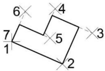
text_image
6 4 7 5 3 1 2Key-in: PLACE SHAPE ORTHOGONAL
A shape element can have 3-100 vertices. To place a "shape" with over 100 vertices, use the Place SmartLine tool (see page 2-17) in the Linear Elements tool box.
In 3D, the Place Orthogonal Shape tool forces the shape vertices to be planar. If non-planar data points are entered, the vertices of the shape are forced to a plane defined by the first three non-colinear vertices.
Place Regular Polygon

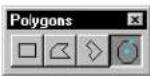
Used to place a regular polygon — a shape with 3–100 equal length sides and equal angles at each vertex. For example, a square is a four-sided regular polygon.
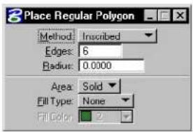
text_image
Place Regular Polygon Method: Inscribed Edges: 6 Radius: 0.0000 Area: Solid Fill Type: None Fill Color: 2| Tool Setting | Effect |
| Method | Sets how a polygon is positioned in the design.Inscribed—Polygon is inscribed in an imaginary circle. If the Radius is keyed in, one vertex is placed at center's right.Circumscribed—Polygon is circumscribed in an imaginary circle. If the Radius is keyed in, the midpoint of one side is placed at center's right.By Edge—One edge is defined graphically. |
| Edges Sets the number of edges (3–100). | |
| Radius | If a non-zero value is keyed in, determines the inscribing or circumscribing circle's radius.If zero, the radius is defined with a data point. |
| Area | Active Area — Solid or Hole. |
| Fill Type | Active Fill Type — None (no fill), Opaque (filled with Active Color), or Outlined (filled with Fill Color). |
| Fill Color | Sets the color with which the polygon is filled.· If Fill Type is Opaque, the Active Color.· If Fill Type is Outlined, the fill color can be different from the Active Color. |
To place a regular polygon with the radius keyed in
- Select the Place Regular Polygon tool.
- In the tool settings window's Radius field, key in a non-zero value.
- Set Method to Inscribed or Circumscribed.
- Enter a data point to define the center.
- Enter a data point to define the orientation.
- (Optional) — Repeat steps 4 and 5 to place an additional polygon.
Place Regular Polygon with Radius keyed in. Metod is Inscribed (left), Circumscribed (right).
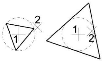
text_image
1 2 1 2To place a polygon with the radius defined graphically
- Select the Place Regular Polygon tool.
- In the tool settings window's Radius field, key in 0.
- Set Method to Inscribed or Circumscribed.
- Enter a data point to define the center.
- Enter a data point to define the radius of the imaginary circle, the polygon's rotation, and one vertex (inscribed) or the center of one side (circumscribed).
- Return to step 4 to place additional polygons or Reset.
Place Regular Polygon with the Radius defined by a data poi Method is Inscribed (left), Circumscribed (right).
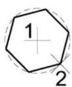
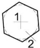
To place a polygon by defining an edge
- Select the Place Regular Polygon tool.
- In the tool settings window, set Method to By Edge.
- Enter a data point to define one vertex.
- Enter a data point to define the other vertex of that edge.
Place Regular Polygon, By Edge.
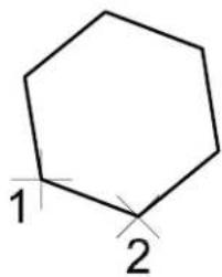
text_image
1 2Key-in: PLACE POLYGON ICON
Key-in: PLACE POLYGON[INSCRIBED | CIRCUMSCRIBED | EDGE]
Setting the Active Point
In the Tool Settings window of the tools in the Points tool box, the Point Type is set as follows.
| Point Type | The Active Point is |
| Element A zero-length line (point element). | |
| Character The character (or symbol if the Active Font is a symbol font) specified in the Character field at the:Active Font, Height and Width, which are set on the General tab on the Text Style Editor dialog box (opened by choosing Text Styles from the Element menu).Active Angle. | |
| Cell | The Active Point Cell at the Angle and Active Scale. |
To designate a zero-length line as the Active Point 1. From the Point Type option menu, choose Element.
To designate a character as the Active Point 1. In the Character field, key in the character.
To designate a cell as the Active Point 1. Key in the cell name in the Cell field (or use the Cell Library dialog box, which is opened by choosing Cell Browse button.
Points tool box
The tools in the Points tool box are used to place the Active Point (see "Setting the Active Point" on page 2-53).
An active point is used as a reference or monument point in the design plane. It can consist of a cell from the attached cell library, a text character, a symbol, or a line with no (zero) length (a "point" element).
The Active Angle for placement is set in the DGN File Settings dialog box (Settings menu > Design File...). The Active Scale for cell placement is also set in the DGN File Settings dialog box. The Active Font, Text Height, and Text Width for character placement are set in the Text dialog box (Element menu > TextStyles ).
| To | Select in the Points tool box |
| Place the Active Point. |  Place Active Point (see page 2-56) Place Active Point (see page 2-56) |
| Construct equally spaced Active Points between two data points. |  Construct Points Between Data Points (see page 2-57) Construct Points Between Data Points (see page 2-57) |
| Place the Active Point on an element at the point closest to the data point. |  Project Active Point Onto Element (see page 2-59) Project Active Point Onto Element (see page 2-59) |
| Construct a point at intersection | [DGDB]Construct Active Point at Intersection (see page 2-61) |
| Construct a specified number of Active Points along an element between two data points. |  Construct Points Along Element (see page 2-62) Construct Points Along Element (see page 2-62) |
| Construct the Active Point on an element at a keyed in distance. |  Construct Active Point at Distance Along Element (see page 2-64) Construct Active Point at Distance Along Element (see page 2-64) |
Key-in: DIALOG TOOLBOX POINTS [OFF | ON | TOGGLE]
Place Active Point

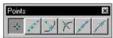
Used to place the Active Point.
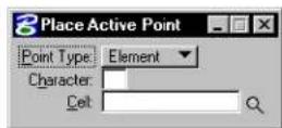
| Tool Setting | Effect |
| Point Type | Sets the Active Point type:Element—A zero-length line.Character—A character.Cell—A cell. |
| Charac-ter | If the Active Point Type is Character, the character or symbol. |
| Cell | If the Active Point Type is Cell, the Active Point Cell. |
| Browse Cell(s) | Opens the Cell Library dialog box for setting an Active Point Cell. |
To place the Active Point
- Select the Place Active Point tool.
- Enter a data point to position the Active Point.
- Continue to enter data points to place the same Active Point.
Place Active Point. AA denotes the Active Angle.
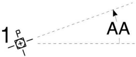
text_image
1 P + - AAKey-in: PLACE POINT

For information about setting the Active Point, see "Setting the Active Point" on page 2-53.
Construct Points Between Data Points

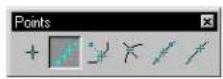
Used to construct a number of equally spaced Active Points between two data points.
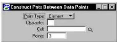
text_image
3 Construct Pnts Between Data Points Point Type: Element Character: Cell: Points: 3| Tool Setting | Effect |
| Point Type | Sets the Active Point Type:Element—A zero-length line.Character—A character.Cell—A cell. |
| Charac-ter | If the Active Point Type is Character, the character. |
| Cell | If the Active Point Type is Cell, the Active Point Cell. |
| Browse Cell(s) | Opens the Cell Library dialog box for setting an Active Point Cell. |
| Points | Sets how many Active Points are constructed. |
To construct Active Points between data points
- Select the Construct Active Points Between Data Points tool.
- Enter a data point to define the location of the first Active Point.
- Enter a second data point to define the location of the last Active Point.
The remaining Active Points are equally spaced between the two data points.
- Continue from step 3 to enter additional Active Points from the last data point entered, or Reset to return to step 2.
Construct Active Points Between Data Points
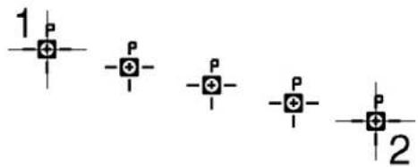
text_image
1 P -P -I -P -I -P -I P 22-58 MicroStation User Guide
Key-in: CONSTRUCT POINT BETWEEN

For information about setting the Active Point, see "Setting the Active Point" on page 2-53.
Project Active Point Onto Element

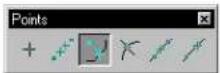
Used to construct the Active Point on an element at the point closest to the data point.
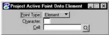
text_image
Project Active Point Onto Element Point Type: Element Character: Cell:| Tool Setting | Effect |
| Point Type | Sets the Active Point Type:Element—A zero-length line.Character—A character.Cell—A cell. |
| Charac-ter | If the Active Point Type is Character, the character. |
| Cell | If the Active Point Type is Cell, the Active Point Cell. |
| Browse Cell(s) | Opens the Cell Library dialog box for setting an Active Point Cell. |
To project the Active Point onto an element
- Select the Project Active Point Onto Element tool.
- Identify the element. See "Identifying elements" on page 3-2.
- Enter a data point to project the Active Point—that is, place it on the element at the point closest to the data point.
Project Active Point Onto Element
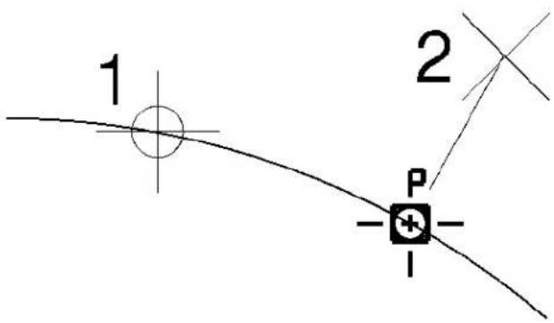
text_image
1 2 P -+- -Key-in: CONSTRUCT POINT PROJECT
For information about setting the Active Point, see "Setting the Active Point" on page 2-53.
Construct Active Point at Intersection

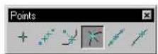
Used to construct the Active Point at the intersection of two elements.
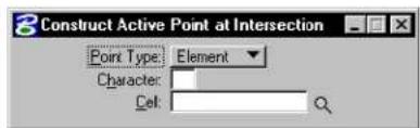
text_image
Construct Active Point at Intersection Point Type: Element Character: Cell:| Tool Setting | Effect |
| Point Type | Sets the Active Point Type:Element—A zero-length line.Character—A character.Cell—A cell. |
| Charac-ter | If the Active Point Type is Character, the character. |
| Cell | If the Active Point Type is Cell, the Active Point Cell. |
| Browse Cell(s) | Opens the Cell Library dialog box for setting an Active Point Cell. |
To construct an Active Point at an intersection
- Select the Construct Active Point at Intersection tool.
- Identify the first element close to the desired point of intersection.
See "Identifying elements" on page 3-2.
- Identify the second element.
- Accept the construction.
Construct Active Point at Intersection
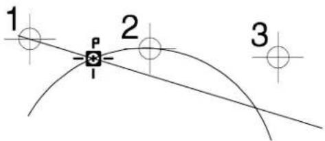
text_image
1 2 3Key-in: CONSTRUCT POINT INTERSECTION

For information about setting the Active Point, see "Setting the Active Point" on page 2-53.
Construct Points Along Element

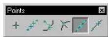
Used to construct the Active Point a specified number of times along an element between two data points. The distance along the element between each instance of the Active Point is the same.
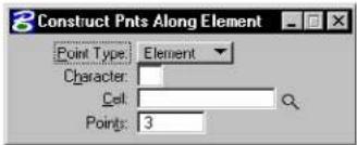
text_image
Construct Pnts Along Element Point Type: Element Character: Cell: Points: 32-62 MicroStation User Guide
| Tool Setting | Effect |
| Point Type | Sets the Active Point Type:Element—A zero-length line.Character—A character.Cell—A cell. |
| Charac-ter | If the Active Point Type is Character, the character. |
| Cell | If Active Point Type is Cell, the Active Point Cell. |
| Browse Cell(s) | Opens the Cell Library dialog box for setting an Active Point Cell. |
| Points | Sets how many Active Points are constructed. |
To construct Active Points along an element
- Select the Construct Active Points Along Element tool.
- Identify the element to define one end of the segment on which to construct Active Points. See "Identifying elements" on page 3-2.
- Enter a data point to define the other end of the segment.
Construct Active Points Along Element

text_image
1 P P P P P 2Key-in: CONSTRUCT POINT ALONG

For information about setting the Active Point, see "Setting
the ActivePoint" on page 2-53.
Construct Active Point at Distance Along Element


Used to construct the Active Point on an element at a keyed-in Distance from where the element is identified.
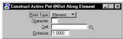
text_image
3 Construct Active Pnt @Dist Along Element Point Type: Element Character: Cell: Distance: 1.0000| Tool Setting | Effect |
| Point Type | Sets the Active Point Type: Element—A zero-length line. Character—A character. Cell—A cell. |
| Charac-ter | If the Active Point Type is Character, the character. |
| Cell | If the Active Point Type is Cell, the Active Point Cell. |
| Browse Cell(s) | Opens the Cell Library dialog box for setting an Active Point Cell. |
| Distance | Sets the distance along the element from the point identified in step 2 (see page 2-65) at which the active point is constructed. |
To construct the Active Point at a distance along an element
- Select the Construct Active Point at Distance Along Element tool.
- Identify the element at the point from which to measure the distance. See "Identifying elements" on page 3-2.
- Enter a data point to define the direction in which to construct the Active Point.
Construct Ative Point at Distance Along Element
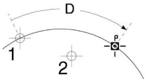
text_image
D 1 P 2Key-in: CONSTRUCT POINT DISTANCE

For information about setting the Active Point, see "Setting the Active Point" on page 2-53.
Arcs tool box
The tools in the Arcs tool box are used to place and modify arcs.
| To | Select in the Arcs tool box |
| Place a circular arc. |  Place Arc (see page 2-67) Place Arc (see page 2-67) |
| Place an elliptical arc with a sweep angle of 180°. |  Place Half Ellipse (s page 2-70) Place Half Ellipse (s page 2-70) |
| Place an elliptical arc with a sweep angle of 90°. |  Place Quarter Ellipse (see page 2-71) Place Quarter Ellipse (see page 2-71) |
| Modify a circular arc's radius, sweep angle, and center. |  Modify Arc Radius (see page 2-72) Modify Arc Radius (see page 2-72) |
| Extendorshortenanarc's (sweep angle). |  Modify Arc Angle (se page 2-73) Modify Arc Angle (se page 2-73) |
| Lengthen or shorten an axis of an arc. |  Modify Arc Axis (see page 2-74) Modify Arc Axis (see page 2-74) |
Key-in: DIALOG TOOLBOX ARC [OFF | ON | TOGGLE]

To modify a circular arc's radius (or both axes of an elliptical arc), without changing the center or sweep angle, use the Element Selection tool (see page 4-2).
Place Arc

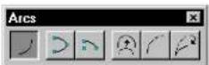
Used to place a circular arc. Arcs can be placed clockwise or counterclockwise.

text_image
Place Arc Method Center Radius: 0.0000 Length: 0.0000 Stat Angle: 0.0000° Sweep Angle: 0.0000°| Tool Setting | Effect |
| Method Two options for Method:Center—position by an endpoint, the center, and a point that defines the sweep angle.Edge—position by three points on the arc edge. | |
| Radius If on, sets the radius. | |
| Length If on, sets the length of the arc. | |
| Start Angle | If on, sets the angle between an imaginary line between the center and the arc's beginning and the view's x-axis. |
| Sweep Angle | If on, sets the arc's sweep angle. |
To place an arc by its center
- Select the Place Arc tool.
- Set Method to Center.
-
Enter a data point to define the arc's beginning, from which the arc extends. or If Radius, Start Angle, and Sweep Angle are all on, enter a data point to define the arc's center and place the arc.
-
If necessary, enter a data point. If Radius and Start Angle are on, this data point defines the arc's sweep angle and places the arc. If Sweep Angle is on, this data point defines the arc's center and places the arc. Otherwise, this data point defines the arc's center.
-
If necessary, enter a data point to define the arc's sweep angle and place the arc.
Place Arc, with Method set to Center. Left: All constraints off. Right: All constraints on. Radius, denoted by "R." Start Angle, denoted by "ST." Sweep Angle, denoted by "SW."
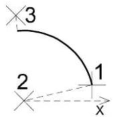
text_image
3 2 1 x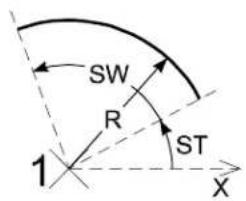
text_image
SW R ST 1 XArcs (with Method set to Center) can be placed with counterclockwise (left) or clockwise (right).
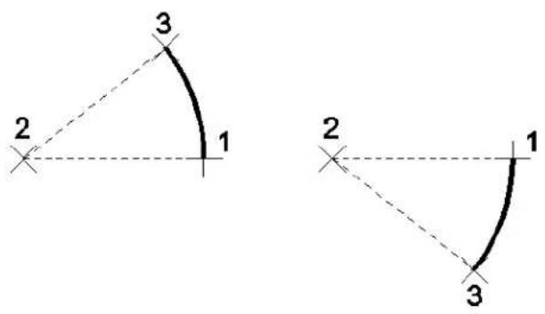
text_image
3 2 1 2 1 3To place an arc defined by three points
- Select the Place Arc tool.
- Set Method to Edge.
- Enter a data point to define the arc's beginning.
If Radius, Start Angle, and Sweep Angle are all on, the arc is placed. - If necessary, enter a second data point to define a point on the arc.
- If necessary, enter a third data point to define the endpoint and sweep angle.
Place Arc, with Method set to Edge. Left: All constraints off. Right: All constraints on. Radius, denoted by "R." Start Angle, denoted by "ST." Sweep Angle, denoted by "SW."
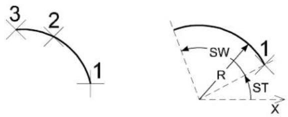
text_image
3 2 1 SW R ST X 1Key-in: PLACE ARC ICON
Key-in: PLACE ARC

To dynamically change the direction of a circular arc while placing it by its center point, use the Place SmartLine tool (see page 2-17).
Place Half Ellipse

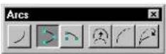
Used to place an elliptical arc with a sweep angle of 180^ .

To place a half ellipse
- Select the Place Half Ellipse tool.
- Enter a data point to define one end of the primary axis.
- Enter a second data point at a point on the ellipse.
- Enter a third data point to define the other end of the primary axis.
Place Half Ellipse
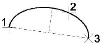
text_image
1 2 3Key-in: PLACE ELLIPSE HALF
2-70 MicroStation User Guide
Place Quarter Ellipse

Used to place an elliptical arc with a sweep angle of 90^ .
To place a quarter ellipse
- Select the Place Quarter Ellipse tool.
- Enter a data point to define one endpoint.
- Enter a second data point to define the orientation of an axis.
- Enter a third data point to define the other endpoint.
Place Quarter Ellipse
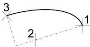
text_image
3 1 2Key-in: PLACE ELLIPSE QUARTER
Modify Arc Radius

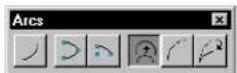
Used to modify the radius, sweep angle, and center of a circular arc. The endpoints do not move.
To modify an arc's radius
- Select the Modify Arc Radius tool.
- Identify the arc.
- Enter a data point to redefine the radius, sweep angle, and center.
Modify Arc Radius
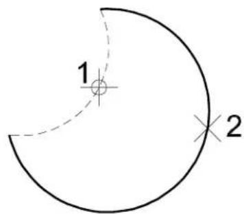
text_image
1 22-72 MicroStation User Guide
To modify an arc's radius without changing the center or sweep angle
- Select the Element Selection tool.
- Select the arc.
- Drag the midpoint handle to define the new radius.
Key-in: MODIFY ARC RADIUS
To modify an arc's radius with greater precision, use the Modify Element tool (see page 4-90) in conjunction with AccuDraw.
Modify Arc Angle

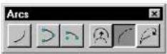
Used to extend or shorten the length (sweep angle) of an arc.
To modify an arc's sweep angle
- Select the Modify Arc Angle tool.
- Identify the arc close to the end to modify.
- Enter a data point to lengthen or shorten the arc.
Alternative method — To modify an arc's sweep angle
- Select the Element Selection tool.
- Select the arc.
- Drag the endpoint handle(s) to lengthen or shorten the arc.
Modify Arc Angle. At left, shortening the arc. At ght, lengthening the arc.
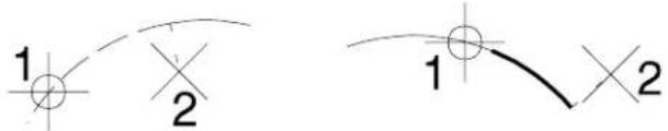
text_image
1 2 1 2Key-in: MODIFY ARC ANGLE

To modify an sweep angle with greater precision, use the Modify Element tool (see page 4-90) in conjunction with AccuDraw.
Modify Arc Axis

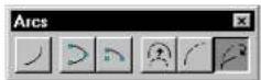
Used to lengthen or shorten an axis of an arc.
To modify an arc's axis
- Select the Modify Arc Axis tool.
- Identify the arc near the axis to modify.
- Enter a data point to redefine the axis.
Modify Arc Axis
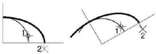
text_image
1 2 1 2Key-in: MODIFY ARC AXIS

If the sweep angle is less than 90^ , only one axis can be modified.
Using the Select Settings Window
To streamline the drawing of real world objects and promote consistency with project drawing standards, you can use the Select Settings window. This window enables you to adjust the active settings and select a drawing tool with a click or two, thereby bypassing the dialog boxes and tool boxes.
(Default) Select Settings window

text_image
Select Settings: [styles.stg] File Category Style Sort Options Group V40 - Dimension Styles Component ANSIY14.5 MechanicalTempla(Docked) Select Settings window
(Large) Select Settings window (Options > Large Dialog)
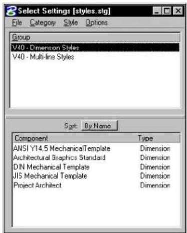
text_image
Select Settings [styles.stg] File Category Style Options Group V40 - Dimension Styles V40 - Multi-line Styles Sort By Name Component Type ANSI Y14.5 MechanicalTemplate Dimension Architectural Graphics Standard Dimension DIN Mechanical Template Dimension JIS Mechanical Template Dimension Project Architect DimensionSome setup is required to use the Select Settings window: settings groups must be defined, based on the project's drawing standards, and stored in settings files. Typically the site or project manager does this.
To open an existing settings file
- From the Settings menu, choose Manage.
The Select Settings window opens. The default settings file, as displayed in the Select Settings window's title bar, is "styles.stg".
- From the window's File menu, choose Open.
The Open Existing Settings File dialog box opens.
- Select a settings file (a file with the extension .stg) and click OK.
To open a remote settings file
- From the Settings menu, choose Manage.
The Select Settings window opens.
- From the window's File menu, choose Open URL.
The Select Remote Settings File dialog box opens. The controls in this dialog box are analogous to those in the Select Remote Design to Attach dialog box. For more information on these controls, see the "Select Remote Design to Attach
dialog box" in the online Reference Guide.
- In the URL field, specify the path to the remote settings file.
- (Optional) — Adjust any other settings necessary.
- Click OK.
Components
Within a drawing settings group, settings are further grouped into components. Like the parent settings group, the components are typically named for real world objects. These are the types of components:
| Component Type | Used to place |
| Linear | Lines, arcs, ellipses, line strings, shapes, curves, complex chains, or complex shapes |
| Text Text (See “Text Labels” in the Guide to Generating Drawings.) | |
| Cell Cells | |
| Point | Points |
| Area Pattern | Pattern cells |
| Dimension | Dimensions (See “Dimensioning” in the Guide to Generating Drawings.) |
| Multi-line | Multi-lines |
General Procedure — To work with drawing settings groups
- From the Settings menu, choose Manage.
The Select Settings window opens. The drawing settings groups in the open settings file are listed in the Group list box. - In the Group combo box, select a group.
- In the Component combo box, select a component.
The active settings are set to those of the component.
If the component definition specifies a key-in, the corresponding tool is selected.
-
Place an element.
-
Place another element using the same settings (return to step 4).
or Select a different component (return to step 3). or Select a different group (return to step 2).
Other categories of settings groups
There are other categories of settings groups, which can be selected from dialog boxes that are opened from the Select Settings window's Categories menu.
Scale settings groups
A scale settings group specifies plotting units relative to design master units. Scale settings groups are optionally used:
- In conjunction with Cell, Active Point, and Area Pattern drawing settings group components, to scale cells while placing them. See "Using Cells" on page 5-1.
- In conjunction with Text and Active Point drawing settings components, to control the sizing and spacing of text while placing it. See "Text Labels" in the Guide to Generating Drawings for a description on how to perform this task.
To select (and activate) a scale settings group
- From the Settings menu, choose Manage.
The Select Settings window opens.
- From the Category menu, choose Scale.
The Select Scale dialog box opens.
-
In the list box, select the desired group.
-
Click the OK button.
Activating a scale settings group cannot have an effect on the active scale factors until you select a Cell drawing component (or an Active Point or Area Pattern component that specifies a cell). Similarly, activating a scale settings group cannot have an effect on the active text settings until you select a Text component (or an Active Point component that specifies a text character).
Working units settings groups
A working units settings group consists of Working units settings. Working units settings groups are used in conjunction with Cell, Active Point, and Area Pattern drawing settings group components to scale cells while placing them. See “Using Cells” on page 5-1.
Selecting a working units settings group adjusts the active design file's working units settings in the same manner as using the controls in the Working Units category of the Design File Settings dialog box.
Changing the Master Units on the Working Units category on the Design File Setting dialog box automatically updates the Sub Units accordingly.
3
Drawing Technique
When you work with CAD drawings, your screen pointer is an important line of communication between you and the system as you create your drawing, or model. You can use the screen pointer to select tools, identify elements, and position elements in the model. Used in conjunction with AccuDraw, the screen pointer lets you work both quickly and with precision. For many operations, the screen pointer can be thought of as a very powerful replacement for your pen or pencil in manual drafting. Similarly, AccuDraw can be thought of as a very powerful replacement for your drafting machine, tee-square, calculator, just to name a few items. In manual drafting, you quite often begin new lines at the end of existing lines, or at the intersection point with existing lines. Similarly, with your CAD drawing, you have to be able to reproduce these techniques. MicroStation provides you with all the tools necessary to create 2D drawings or models. Additionally, with MicroStation, you can work in a 3D environment, creating a 3D model of your design. Working in 3D is covered elsewhere. In this chapter, you will find out how to use the numerous 2D drafting aids in MicroStation, including:
• Identifying Elements (see page 3-2)
- Snapping to Points on Elements (see page 3-3)
• Working with AccuDraw (see page 3-26)
- Selecting Elements (see page 3–76)
• Manipulating and Modifying Selected Elements (see page 3-77)
• Using the Fence to Manipulate and Modify Elements (see page 3-80)
• Using the Grid (see page 3-86)
- Precision Input key-ins (see page 3-91)
• Using the Tools in the Measure tool box (see page 3-95)
Identifying Elements
Many of the operations that you perform in a design session rely on the ability to identify existing elements, or to pick specific points on those elements. MicroStation provides the tools to perform these tasks. You can quickly and conveniently identify elements, or keypoints on elements, using tentative snap points and data points.
Identifying elements manually
Many tools require that you identify one or more elements. You can do this manually by placing the pointer over the element and entering a data point to highlight the element. If you want to preview which element is being selected, you can enter tentative snap points first, until the correct element highlights, and then accept with a data point.
For information on entering data points and tentative snap points, see "MicroStation and Graphical Input" in the QuickStart Guide.
AccuSnap
AccuSnap automates the identification of elements and the placement of tentative snap points, so that you don't have to enter all tentative snap points manually. You can turn on the Enable AccuSnap setting in the General tab of the AccuSnap Settingsdialog box to automatically locate and snap a tentative point to elements. You simply move the screen pointer to the region of the element that you want to identify and AccuSnap snaps to it automatically.

Even with AccuSnap enabled, you can still enter tentative snap points manually.
Automatic identification of elements
Another setting can be used in conjunction with AccuSnap to automatically identify elements for various tools. This feature
is enabled with the Identify Elements Automatically setting in the AccuSnap Settings dialog box, General tab. Like AccuSnap, this setting can greatly reduce the number of button presses required in a design session. Using this setting with the Delete tool, for example, you only have to move the screen pointer over the required element in any view and it highlights. A single data point then deletes the highlighted element.
Pop-up Info
As part of the automatic element identification functions, you can turn on Pop-up Info in the AccuSnap Settings dialog box, General tab. With this setting enabled, when you hover, or pause, the pointer over a highlighted element, information about it appears in a pop-up window.
Snapping to Points on Elements
During a drawing session, much of your time will revolve around joining new elements to existing elements in the design, or modifying existing elements. In manual drafting, this is done by eye. With MicroStation, you can work precisely, letting the system find the exact location of elements, or various points on elements. You can define points relative to other points as well. All this is done using tentative snap points.
Tentative snap points
A tentative snap point is a form of graphic input that is used to:
- Preview the location of the next data point. Accepting the tentative point location enters the data point there.
- Define a point of reference for entry of the next data point.
It is also possible to snap a tentative point to an existing element (put it directly on the element). Tentative point snapping helps
you accurately construct new elements that are either connected to existing ones or precisely related to existing ones.
Using tentative snaps, for example, you can:
- Place a line from the exact end point of an existing element to the midpoint of another.
- Place a line perpendicular or parallel to another line.
- Place a circle tangent to an arc or a B-spline curve.
- Place a cell at the centroid of a shape.
Snapping to tentative points on elements
Snapping is affected by the Snap Lock settings. There are three basic Snap Lock settings: the snap on/off toggle, the Snap Mode, and the Snap Mode override.
Snap Lock
If the Snap Lock toggle is off, tentative points do not snap to elements.
Snap Mode
When Snap Lock is on, how a tentative point snaps to an element is set by the active Snap Mode (or the override setting if one is active).

You can set the default Snap Mode via the Locks dialog box, the Snap Mode button bar, the pointer's pop-up menu, or the status bar menu. The Snap Mode (or Snap Mode override) is indicated in the status bar.
To set the Snap Mode via the Locks dialog box
- From the Settings menu's Locks submenu (or the pop-up Locks menu in the status bar), choose Full.
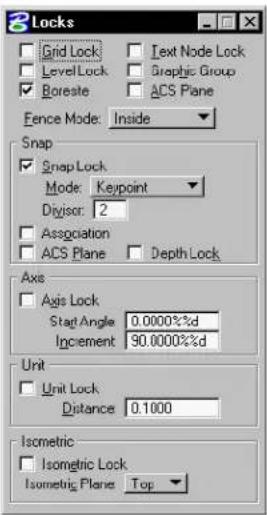
text_image
Locks Grid Lock LevelLock Boreste Text Node Lock Graphic Group ACS Plane Fence Mode: Inside Snap Snap Lock Mode: Keypoint Divisor: 2 Association ACS Plane Depth Lock Axis Axis Lock Start Angle 0.0000%d Increment 90.0000%d Unit Unit Lock: Distance 0.1000 Isometric Isometric Lock Isometric Plane TopThe Locks dialog box opens.
- From the Snap section, Mode option menu, choose the desired snap mode.
To set the Snap Mode via the Snap Mode button bar
- From the Settings menu's Snaps submenu (or the pop-up Snaps menu in the status bar), choose Button Bar.
The Snap Mode button bar opens.
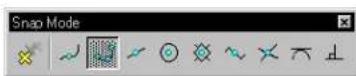
- In the button bar, double-click the desired snap mode.
The active Snap Mode's button is highlighted with speckled gray.
To set the Snap Mode via the Snap Modes pop-up menu
-
Place the pointer in any view.
-
Hold down the Shift key.
The pop-up Snap Modes menu opens. A button with a filled black circle is displayed to the left of the active Snap Mode.
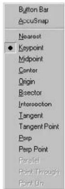
text_image
Button Bar AccuSnap Nearest ● Keypoint Midpoint Center Origin Bisector Intersection Tangent Tangent Point Perp Perp Point Parallel Point Through Point On-
While still holding down the Shift key, click the desired Snap Mode (or drag the pointer to it and release the Tentative button).
-
Release the Shift key.
To set the Snap Mode via the status bar
-
Place the pointer in the Snap Mode field located on the status bar.
-
Click the Data button.
The pop-up Snap Modes menu opens. A button with a filled black circle is displayed to the left of the active Snap Mode.
-
While holding down the Shift key, choose the desired Snap Mode by clicking it (or drag the pointer to it and release the Data button).
-
Release the Shift key.
The Snap Modes button bar is dockable and resizable.
Snap Mode override
During a session, most likely you will use a particular Snap Mode for a majority of operations, but occasionally you want to use a different snap mode. At any time, you can override the active Snap Mode for a single snap by choosing a Snap Mode override. The override mode is effective only for the next operation. After you have snapped a tentative point and accepted with a data point (or Reset), the override is cancelled and the active Snap Mode becomes effective again.
You can set the Snap Mode override via the Settings menu's Snaps submenu, the Snap Mode button bar, the pointer's pop-up menu, or the status bar menu. The active Snap Mode, or Snap Mode override, is indicated in the status bar.
To set the Snap Mode override via the Settings menu
- From the Settings menu's Snaps submenu, choose the desired Snap Mode override.
If you open the menu again, you will see that the snap override has a button with a filled black circle to its left, while the active snap mode has an open black circle to its left.
To set the Snap Mode override via the Snap Mode button bar
- From the Settings menu's Snaps submenu (or the pop-up Snaps menu in the status bar), choose Button Bar.
The Snap Mode button bar opens.
- In the button bar, select the desired Snap Mode override.
The Snap Mode override's button is highlighted with light gray; while the active Snap Mode's button remains highlighted with speckled gray.
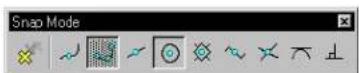
To set the Snap Mode override via the Snap Modes pop-up menu
-
Place the pointer in any view.
-
While holding down the
key, click the Tentative button.
The pop-up Snap Modes menu opens. If a Snap Mode override is already in effect, a button with a filled black circle is displayed to the left of the override and an open black circle is displayed to the left of the active Snap Mode. Otherwise, the button with a filled black circle is displayed to the left of the active Snap Mode.
-
Release the 〈Shift〉 key.
-
Choose the desired Snap Mode override by clicking it (or drag the pointer to it and release the Tentative button).
To set the Snap Mode override via the status bar
- In the status bar, click the Snap Mode indicator.
The pop-up Snap Modes menu opens.
- Choose the desired Snap Mode override by clicking it (or drag the pointer to it and release the Data button).
Effect of Snap Modes
With Snap Lock on, each snap mode setting has an effect on tentative snap points. When you enter a tentative point on or near an element, the following occurs:
| Snap Mode: | Tentative point snaps to: |
| Nearest | Point on the element nearest to the pointer. |
| Snap Mode ^ | Tentative point snaps to: |
| Keypoint |  The nearest of the Element keypoints (see page 3-12) on the element. This is the most generally useful of the snap modes. The nearest of the Element keypoints (see page 3-12) on the element. This is the most generally useful of the snap modes. |
| Midpoint |  Midpoint of the segment of the element closest to the pointer. (For an elliptical arc, the tentative point snaps to the point on the arc at half the swe ep angle, as opposed to the point at half the arc distance.) Midpoint of the segment of the element closest to the pointer. (For an elliptical arc, the tentative point snaps to the point on the arc at half the swe ep angle, as opposed to the point at half the arc distance.) |
| Center |  Center of elements (such as circles, arcs, text, and so on) with centers. Centroid of other elements, including shapes, line strings, and B-splines. Center of elements (such as circles, arcs, text, and so on) with centers. Centroid of other elements, including shapes, line strings, and B-splines. |
| Origin |  Origin of a cell or text, centroid of a B-spline, the first data point in a dimension element, or the first vertex of a line, multi-line, line string, or shape. Origin of a cell or text, centroid of a B-spline, the first data point in a dimension element, or the first vertex of a line, multi-line, line string, or shape. |
| Bisector |  Midpoint of an entire line string, multi-line, or complex chain, rather than to the midpoint of the closest segment. It also snaps to the midpoint of a line or arc. (For an elliptical arc, the tentative point snaps to the point on the arc at half the arc distance, as opposed to the point at half the sweep angle.) Midpoint of an entire line string, multi-line, or complex chain, rather than to the midpoint of the closest segment. It also snaps to the midpoint of a line or arc. (For an elliptical arc, the tentative point snaps to the point on the arc at half the arc distance, as opposed to the point at half the sweep angle.) |
| Snap Mode: | Tentative point snaps to: |
| Intersection | Intersection of two elements. (Two tentative points are required, although more can be used.) The first tentative point snaps to one element, and that element is highlighted. The second tentative point snaps to another element, and the two segments used to find the intersection of the two elements are displayed in dashed lines. (If the two elements do not actually intersect, but projections of the elements would intersect, the segments include projections of the element to the intersection continue snapping until the desired intersection is found; the last two tentative points define where the intersection snap lies. |
| Tangent | An existing element — the edge of the element being placed is constrained to be tangent to an existing element. The tentative point dynamically slides along the element to maintain the tangency as you move the pointer to finish placing the element. |
| Tangent From | An existing element — the edge of the element you are placing is constrained to be tangent to the existing element at the tentative point. The tentative point does not move dynamically as you move the pointer, but is locked in place. |
| Perpendicular | An existing element — the line you are placing is constrained to be perpendicular to the element — the tentative point slides dynamically along the element in order to maintain the perpendicularity as you move the pointer to finish placing the element. |
| Snap Mode: | Tentative point snaps to: |
| Perpendicular From | |
| Parallel | |
| Through Point | |
| Point On |
Or override.
Locate Tolerance
How close the pointer must be to an element in order to snap a tentative point to it depends upon the Locate Tolerance. Locate Tolerance is a user preference that is adjustable in the Input category of the Preferences dialog box (Workspace menu > Preferences). Tolerance values are set in screen resolution (pixels).
Snappingtocells
A cell is a small drawing — usually of a frequently-used or complex symbol, notation, or detail — created in MicroStation. To snap to the origin of a cell, set the Snap Mode to Origin. When the Snap Mode is not set to origin, tentative points snap to component elements within the cell. For example, when the Snap Mode is Keypoint, tentative points will snap to a keypoint on the line, not the origin of the cell.
Element keypoints
Keypoints are regularly-spaced points in an element to which a tentative point will snap when the Snap Mode (or override) is set to Keypoint. The number of keypoints on each segment of a linear element (line, line string, or shape) is one greater than the Snap Lock Divisor setting. If Snap Lock Divisor is 2 (as in all seed files supplied with MicroStation), keypoints are as shown in the figure below. The midpoint of a linear element is a keypoint only if the Snap Lock Divisor is an even number.

For text, the keypoint is determined by the justification attribute. That attribute and others specific to text elements are described in Text Labels.
Element keypoints (with Snap Lock Divisor st to 2 and the text element left top justified). Clockwise from the upper left: Arc, ar, line, line string, text, ellipse, and shape.
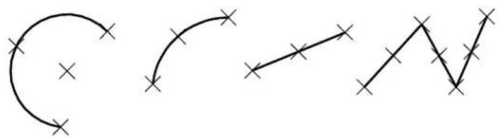
natural_image
Three abstract line drawings with cross marks, no text or symbols present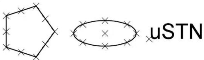
chemical
Chemical structure diagram showing a pentagon and an oval with cross marks, labeled 'uSTN'To enable snapping
- From the Settings menu's Locks submenu (or the pop-up Locks menu in the status bar), choose Full.
The Locks dialog box opens.
- Turn on Snap Lock.
To change the number of element keypoints on each element segment
- From the Settings menu's Locks submenu (or pop-up Locks menu in the status bar) choose Full.
The Locks dialog box opens.
- Set Snap Lock Divisor to a value one less than the desired number of keypoints.
For example, to create element keypoints on the endpoints and the first, second, and third quarter points of element segments, set Snap Lock Divisor to 4.
Using AccuSnap
AccuSnap provides tentative snap functionality, which may be used standalone or in combination with AccuDraw. It provides graphical assistance — a “smart” pointer — for snapping to elements. This automates the tentative snap process, virtually eliminating the need to press the tentative snap button, thus reducing the number of “button presses” required during a design session. When in AccuSnap mode, you simply select a tool and move the pointer over the elements, letting AccuSnap find and display the nearest tentative snap point for you. When the correct snap point is displayed, you enter a data point to accept. If required you can adjusting various AccuSnap settings to configure AccuSnap for your mode of operation.
AccuSnap complements the standard, or manual, method of placing
tentative points. That is, even with AccuSnap enabled, you can still use the standard tentative snap method (pressing the tentative button). Additionally, when you are using AccuSnap in conjunction with AccuDraw, you can use AccuDraw shortcuts, which include to suspend AccuSnap for one point, and
Turning AccuSnap On or Off
AccuSnap can be toggled On or Off:
• In the AccuSnap Settings dialog box (Enable AccuSnap setting).
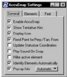
text_image
AccuSnap Settings General Elements Feel Enable AccuSnap Show Tentative Hint Display Icon Fixed Point for Perp./Tan. From Update Statusbar Coordinates Play Sound On Snap Hide active element Identify Elements Automatically Pop-up Info Automatic- In the Snap Mode button bar (clicking the Toggle AccuSnap button).
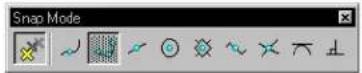
- With AccuDraw active and the focus in the AccuDraw window, using the shortcut
- By pressing (and holding down) the Ctrl + Shift keys), which temporarily toggles AccuSnap on or off. Releasing the Ctrl + Shift keys returns AccuSnap to its previous setting.
AccuSnap settings
AccuSnap works in conjunction with the current Snap Mode setting and, for the most part, is similar in operation to the manual method of tentative snap points — minus the button presses. How close to an element or a keypoint that the pointer must be, before AccuSnap finds it, is governed by the Locate Tolerance setting in the Input category of the Preferences dialog box. These settings can be further refined by the following settings in the AccuSnap Settings dialog box's Feel tab:
- Snap Tolerance — for locating elements.
- Keypoint Sensitivity — for locating snap points.
Location of snap points on elements still is controlled by the Snap Mode setting.
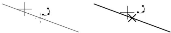
text_image
Two diagrams showing geometric construction with plus and cross symbols, possibly illustrating a linear transformation or projection.With both Show Tentative Hint, and Display Icon turned on. Left: With the pointer within the snap tolerance of an element, AccuSnap shows a prospective snap point with a crosshair (+), along with the current snap mode icon. Right: When the pointer is within Keypoint Sensitivity range, AccuSnap highlights the element and displays the tentative snap point as a heavy line weight "X". A data point at this stage will be placed at the tentative snap point location.
Settings in the AccuSnap Settings dialog box are divided into three tabbed sections — General, Elements, and Feel.
General settings
Settings in this group let you enable/disable AccuSnap and you can define AccuSnap's general working mode. By default, Show Tentative Hint and Display Icon are enabled. Both settings give visual feedback on the snapping point and the current snap mode, respectively. Show Tentative Hint is very useful as it shows you visually where the nearest snap point is, even though the pointer
may not be in the near vicinity of the snap point.
Show Tentative Hint — With Show Tentative Hint turned on (the default), and snap mode set to Keypoint or Midpoint snap — as you move the pointer over the elements, AccuSnap finds the nearest snap point and displays its location with a crosshair (if the pointer is not within the keypoint snap tolerance), or a heavy line weight "X", denoting a tentative snap point (if the pointer is within the keypoint snap tolerance). A data point at this stage will be placed at the displayed tentative snap point.
Display Icon — if on, the current snap mode icon displays at the snap point, for both the tentative hint and for the tentative point.
Hilite active element — if on, the element highlights as soon as AccuSnap locates it and the tentative hint displays. If off, the active element highlights only when the tentative snap point is displayed.
For information on all general settings, refer to "AccuSnap General Settings" in the online Reference Guide.
Element settings
Controls in this group let you control whether or not AccuSnap snaps to Curves, Dimensions, and/or Text. When snapping is turned off for any of these, AccuSnap will not snap to the particular element, but it will display an icon to show that the element is being ignored.

Even if snapping to an element is turned off in AccuSnap's settings, you can still snap to the element manually with a tentative snap point.
With Curves turned off, AccuSnap displays an icon to show that the B-spline curve is being ignored.
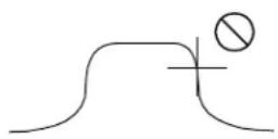
Feel settings
Using the controls in the Feel group of the AccuSnap settings you can set AccuSnap's sensitivity when snapping to elements, as follows:
- Keypoint sensitivity — lets you adjust how close the screen pointer must be, to the snap point, before AccuSnap snaps to it.
- Stickiness — lets you adjust the sensitivity of AccuSnap to the current element. When you have snapped to an element, as long as you move the pointer along that element, the snap system will have a preference for that element over other elements that may have snap points closer to the pointer. The further to the right (+) that you set the Stickiness slider, the further away from the element the pointer may be before AccuSnap will snap to another element.
- Snap Tolerance — lets you adjust how close the pointer must be to an element in order to snap a tentative point to it.
AccuSnap and Snap Mode settings
AccuSnap enhances many of the standard snap mode settings by displaying and automatically snapping to the next tentative snap point as you move the pointer over an element. With AccuSnap enabled, you very rarely need to enter a tentative snap point manually. In the following examples, it is assumed that a tool has been selected and that Show Tentative Hint and Display Icon are enabled (the default settings).
Near Snap Point
When working with this snap mode, manually, you move the pointer to the position that you want the snap to be located and then enter a tentative snap point, followed by a data point to accept the location. If the location is incorrect, you move the pointer along the element and enter another tentative snap point.
With AccuSnap, as you move the pointer to the required element, it highlights and the proposed tentative snap point marker displays. To position the "nearest" snap point, you simply move the pointer along the highlighted element, until the required location is reached, and enter a data point.
To select a near snap point (with AccuSnap)
- Select Near Snap Point mode.
- With AccuSnap enabled, move the pointer over the required element.
The element highlights, and AccuSnap displays the nearest tentative snap point. - Move the pointer, and tentative snap point, along the element to the required position.
- Enter a data point to accept the tentative snap point.
Keypoint Snap
When you move the pointer over an element in the design, AccuSnap displays the nearest keypoint snap with the crosshair hint, or the tentative point marker if the pointer is within the Keypoint Sensitivity range. To select a different keypoint, simply move the pointer to the required region of the element and AccuSnap will again show you where the nearest keypoint is located.
To select a keypoint snap point (with AccuSnap)
- Select Keypoint Snap mode.
- With AccuSnap enabled, move the pointer over the required element.
AccuSnap displays the nearest keypoint snap. - If necessary, using the tentative hint as a guide, move the pointer toward the required snap point until the tentative snap point marker displays.
- Enter a data point to accept the tentative snap point.
Midpoint Snap
When you move the pointer over an element, AccuSnap displays the Midpoint Snap location with the crosshair hint, or the tentative snap point marker if the pointer is within the Keypoint Sensitivity range of the midpoint.
To select the midpoint of an element (with AccuSnap)
- Select Midpoint Snap mode.
- Move the pointer over the required element.
AccuSnap displays the element's midpoint location. - If necessary, using the tentative hint as a guide, move the pointer toward the required snap point until the tentative snap point marker displays.
- Enter a data point to accept the tentative snap point.
Center Snap
When Center Snap is active, the pointer does not have to be close to the actual center point of the element, whether it be a line string, curve, arc, or circle. As soon as you place the pointer over an element, AccuSnap highlights the element and displays the tentative snap point marker at its center point.
To select the center point of an element (with AccuSnap)
- Select Center Snap mode.
- Move the pointer over the required element.
The element highlights and AccuSnap displays the tentative snap point marker at the center point of the element. - Enter a data point to accept the tentative snap point.
Origin Snap
When you create an element, the first point defined is its origin. With Snap Mode set to Origin Snap, as you move the pointer over an element, AccuSnap displays its origin point location with the crosshair hint, or the tentative snap point marker if the pointer is within the Keypoint Sensitivity range.
To select the origin point of an element (with AccuSnap)
- Select Origin Snap mode.
- Move the pointer over the required element.
AccuSnap displays the origin point of the element. - If necessary, using the tentative hint as a guide, move the pointer toward the required snap point until the tentative snap point marker displays.
- Enter a data point to accept the tentative snap point.
Bisector Snap
As you move the pointer over an element, AccuSnap displays its bisector point location with the crosshair hint, or the tentative snap point marker if the pointer is within the Keypoint Sensitivity range.
To select the bisector of an element (with AccuSnap)
- Select Bisector Snap mode.
- Move the pointer over the required element.
AccuSnap displays the bisector snap point of the element. - If necessary, using the tentative hint as a guide, move the pointer toward the required snap point until the tentative snap point marker displays.
- Enter a data point to accept the tentative snap point.
Intersect Snap
To select the intersection point of two elements requires you to identify both elements. AccuSnap lets you do this by simply hovering over the intersection point of the two elements, without entering tentative snap points. When the pointer is over the intersection point, the elements highlight, one solid and one dashed, and the tentative point marker displays at the intersection point. Where a number of elements intersect at a common point, you can move the pointer until the correct pair of elements highlight.
In a 3D DGN file, the two intersecting lines may be separated in the view Z direction. By default the element nearest the Active Depth of the view is highlighted as a solid line and it is on this element that the data point will be placed. That is, the new element is attached to the element highlighted as a solid line. You can control this by manually snapping to the required element first, before moving the pointer to the intersection point. That is, snap to the element to which you want the new element attached, then move the pointer to the intersection point. The first element will highlight as a solid line, and the remaining element as dashed.
To select the intersection point of two elements (with AccuSnap)
- Select Intersect Snap mode.
- Move the pointer to the intersection point of the two elements so that the two elements highlight and the snap point marker appears.
- Enter a data point to accept the tentative snap point.
Tangent Snap and Tangent Point Snap
(For AccuSnap, applies only when using the Place SmartLine tool) The Fixed Point for Perp./Tan. From setting in the General tab of the AccuSnap settings determines whether Tangent Snap, or Tangent Point Snap is used when either snap is active.
When you are placing a SmartLine with either Tangent Snap, or Tangent Point Snap, as the active snap mode, setting Fixed Point for Perp./Tan. From to:
- On — sets the snap mode to Tangent Point Snap.
- Off — sets the snap mode to Tangent Snap.
To use Tangent Point Snap with the Place SmartLine tool (with AccuSnap)
- In the AccuSnap Settings dialog box, General tab, turn on Fixed Point for Perp./Tan. From.
- Select either Tangent Snap, or Tangent Point Snap, as the active snap mode.
- Move the pointer over the curved element, so that it highlights and AccuSnap displays the tentative point.
- Enter a data point to accept the tentative snap point.
The SmartLine segment is restricted to being at a tangent from the highlighted element, at the accepted snap point.
To use Tangent Snap with the Place SmartLine tool (with AccuSnap)
- In the AccuSnap Settings dialog box, General tab, turn off Fixed Point for Perp./Tan. From.
- Select either Tangent Snap, or Tangent Point Snap, as the active snap mode.
- Move the pointer over the curved element, so that it is highlighted.
- Enter a data point to accept the element.
As you move the pointer, the SmartLine segment is restricted to remaining at a tangent to the selected curve.
Perpendicular Snap and Perpendicular Snap Point
(For AccuSnap, applies only when using the Place SmartLine tool) The Fixed Point for Perp./Tan. From setting in the General tab of the AccuSnap settings determines whether Perpendicular Snap, or Perpendicular Snap Point is used when either snap is active.
When you are placing a SmartLine with Perpendicular Snap, or Perpendicular Snap Point, as the active snap mode, setting Fixed Point for Perp./Tan. From to:
- On — sets the snap mode to Perpendicular Snap Point.
- Off — sets the snap mode to Perpendicular Snap.
To use Perpendicular Snap Point with the Place SmartLine tool (with AccuSnap)
- In the AccuSnap Settings dialog box, General tab, turn on Fixed Point for Perp./Tan. From.
- Select either Perpendicular Snap, or Perpendicular Snap Point, as the active snap mode.
- Move the pointer over the element, so that it highlights, and
AccuSnap displays the tentative point.
- Enter a data point to accept the tentative snap point.
The SmartLine segment is restricted to being perpendicular to the highlighted element, from the accepted snap point.
To use Perpendicular Snap with the Place SmartLine tool (with AccuSnap)
-
In the AccuSnap Settings dialog box, General tab, turn off Fixed Point for Perp./Tan. From.
-
Select either Perpendicular Snap, or Perpendicular Snap Point, as the active snap mode.
-
Move the pointer over the element, so that it is highlighted.
-
Enter a data point to accept the element.
As you move the pointer, the SmartLine segment is restricted to remaining perpendicular to the selected element.
Using Tentative Points
Tentative points let you see where the next data point will be placed before you are committed. They also let you define a data point relative to the tentative point. You can specify the distance from the tentative point using a key-in or, better still, using AccuDraw and its input window. The exact location of tentative points, on elements, are determined by the current Snap Mode, or snap override, setting.
You can enter tentative snap points manually, or you can turn on AccuSnap and let it display tentative points interactively as you move the pointer over elements in a view. With AccuSnap active, when the Tentative Point marker displays, you can enter a data point to accept it. Even when AccuSnap is active, you can enter a tentative snap point manually, by pressing the Tentative button on your system's graphical input device. For information about determining the location of the Tentative point and other MicroStation buttons, see "MicroStation and Graphical Input" in the QuickStart Guide.
To enter a tentative point (manually) to preview a data point
- Select the required Snap Mode.
- Position the pointer on the location at which you plan to enter a data point.
- Press the Tentative button.
The tentative point coordinates are shown in the status bar. Large crosshairs are displayed. The intersection of the lines in the crosshairs marks the location of the tentative point. If you snap to an element, the element is highlighted.
To accept a tentative point's location and enter a data point there
- With the tentative point location displayed, and the pointer in any view, press the Data button.
- Press the Data button.
When using AccuSnap, to snap to elements, only one button press is required. You let AccuSnap find and display the tentative snap point.
Using AccuSnap to view a tentative point location and place a data point there
- With AccuSnap active, select the required Snap Mode.
- Move the pointer to the required element and then position the pointer so that the Tentative Point marker (a heavy line weight "X") displays.
- Enter a data point to accept the tentative point and place the point.
To manually snap a tentative point to an element at a keypoint
- Select the required Snap Mode.
- Position the pointer on or near the desired keypoint.
- Press the Tentative button.
If the tentative point successfully snaps to the element, the element is highlighted.
▶ Tosnapatentativepointtoanelementwhenmore than one element lies at the desired snap point
-
Enable snapping. See "To enable snapping" on page 3-13.
-
Position the pointer on or near the desired point.
-
Press the Tentative button.
Of the elements at the desired snap point, a tentative point will snap to the element that was placed in the design earliest. That element is highlighted.
- (Optional) — If the desired element was not snapped to (highlighted), press the Tentative button again.
Of the remaining elements at the desired snap point (the ones to which a tentative point has not snapped), a tentative point snaps to the element that was placed in the design earliest. That element is highlighted.
- (Optional) — Repeat step 4 until the desired element is highlighted.
Working with AccuDraw
AccuDraw is a drafting aid that evaluates such parameters as your current pointer location, the previously entered data point, the last coordinate directive, the current tool's needs, and any directive you have entered via shortcut key-ins or AccuDraw options. AccuDraw then generates the appropriate precision coordinates and applies them to the active tool.
A simple example of using AccuDraw
To help you understand what AccuDraw does, the following is a description of a simple design session using AccuDraw and the Place SmartLine (see page 2-17) tool. The task presented is the creation of a simple bracket. If a 3D file is used, the Top view is assumed in the exercise.
The design subject is a simple bracket with the important dimensions nd features noted.
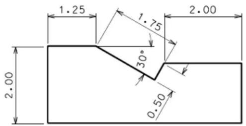
text_image
1.25 1.75 2.00 30° 2.00 0.50With AccuDraw activated (Toggle AccuDraw tool in the Primary Tools tool box), select the Place SmartLine tool in the Linear Elements tool box. When you enter your first data point for the lower left corner of the bracket, AccuDraw displays a square or circular shaped “compass.”
The AccuDraw compass appears whenever AccuDraw is active and a data point is placed.
$$ \begin{array}{c c c} - & - 1 & - \ \frac {1}{-} & \cdot & \frac {1}{-} \ \frac {1}{-} & - 1 & - \end{array} $$
Next, you need to draw the left edge of the bracket. As you move the dynamic line around the view window nothing interesting happens until you get close to one of the axes of the AccuDraw compass. In this case, because you want a vertical edge, you should move the line close to the Y axis. When AccuDraw senses the axis, the line snaps or indexes to it. While the axis is highlighted you can key in a number for the vertical distance, in this case, 2 inches. Don't worry about telling AccuDraw the direction, it has already figured that out and also has placed the input focus (where the key-in data will appear) in the correct field, in this case the Y field. After keying in the distance value, entering a data point results in what you'd expect, a line segment oriented along the vertical axis and exactly two inches long.
The start of the bracket's left edge with its 2 inch measurement courtesy of AccuDraw.
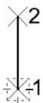
At this point the AccuDraw compass moves to the end point of the line you just placed. Moving the dynamic line segment around, it acts as before. This time you need to place the line with a fixed length of 1.25 inches in the horizontal direction. You do this by moving the dynamic line so that it snaps onto the positive horizontal axis, key in 1.25, and enter a data point.
The bracket's top edge is taking shape a st he indexed line is placed along the horizontal axis.
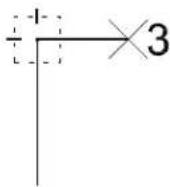
The next part of the bracket involves going off at a 30 degree angle for a given distance. Pressing the Space bar changes the AccuDraw compass to its polar mode (indicated by a circular compass), which lets you enter an angle and a distance. Entering 30 degrees in the Angle field and 1.75 inches in the Distance field locks the line in the right direction. A data point accepts the new location.
The notch appears next with the Polar compass oriented along the new line.
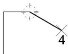
text_image
+ + 4Note how the compass orients along the 30 degree line. This illustrates AccuDraw's context sensitivity. AccuDraw provides a method for associating coordinate information with respect to
existing elements. To place the half inch line at a right angle to the 30 degree line only requires indexing to the appropriate axis, keying in 0.5 and entering a data point to accept.
The notch is nearing completion.
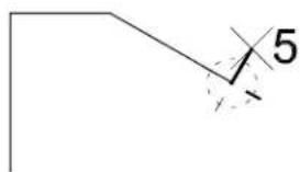
text_image
5With the bracket's notch complete, all that remains is the completion of the bracket's right edge. Currently, however, the compass still is rotated to the 60 degree angle of the notch and not the horizontal direction you need. To override the context nature of AccuDraw you press T to orient the compass to the Top view (the default). Pressing the Space bar brings up the rectangular compass. Indexing, again, to the X axis and keying in 2 inches followed by a data point locks the final known dimension of the bracket.
A quick press of the T key and AccuDraw orients itself to the screen's x and y axes.
text_image
6To “close out” the bracket’s bottom edge, you use the smart axis locking feature of AccuDraw. Moving the pointer down the Y axis you press

Remember that you can use AccuSnap in conjunction with AccuDraw. This speeds up the process of snapping tentative points.
A tentative point on the origin of the bracket results in the dashed index line.
text_image
7The preceding was a very simple example of AccuDraw in action. There is much more to this drafting aid. AccuDraw has been designed with ease of use and a certain intuitive feel to it. As with any drafting aid, you need to try it out first. As you get the hang of it, the various options begin to make sense.
In the following sections, the user interface features of AccuDraw are presented followed by the settings and directives that control its operations.
Activating AccuDraw

Toggle AccuDraw
By default, when MicroStation is started, AccuDraw is loaded automatically. With AccuDraw activated, all drawing tools utilize it for dynamic data input.
To toggle AccuDraw on/off
- In the Primary Tools tool box, select the Toggle AccuDraw tool. The AccuDraw window opens/closes.
Normally, the AccuDraw compass does not appear until you enter the first data point after selecting a tool. AccuDraw's behavior changes slightly with tools that utilize dynamics before the first data point. The Place Text and Place Active Cell tools are examples of such tools. Instead of "waiting" for the first data point to display
the compass, AccuDraw activates the compass at the last data point location. In this way, you can place the element with respect to this location by using any of AccuDraw's relative directives.
AccuDraw also affects operations like placing text or cells in another way. When you place a string of text with AccuDraw active, its initial orientation will be along the current AccuDraw drawing plane. In other words, when you have a Front-oriented drawing plane (see "AccuDraw's drawing plane" on page 3-34), the text will be oriented along the front axis regardless of the view orientation.
AccuDraw will not activate when it would conflict with other tools — for instance, during fence placement and element selection operations, dimensioning, and so on.
Although most users will activate and use AccuDraw during the entire design session, there may be times when its actions might interfere with the current operation. For this reason, AccuDraw can be turned off. MicroStation's tools return to their non-AccuDraw operation.
To deactivate AccuDraw
- In the Primary Tools tool box, select the Toggle AccuDraw tool. or With the focus in the AccuDraw window, press Q .
AccuDraw's compass
AccuDraw's most recognizable feature is its compass. Visible only when AccuDraw is active and has control of MicroStation's coordinate input, the compass acts as both a status indicator and a focus for your input.
AccuDraw
compass.
Left:
Rectangular
coordinate
system.
Right: Polar
coordinate
system.
The origin point
At the center of the compass is AccuDraw's origin point. This is the focal point of all AccuDraw operations. As you select various AccuDraw options, their functions operate from this origin point.
This last point is important. All AccuDraw directives (distance key-ins, shortcut key-ins, and so on) operate in conjunction with the compass. In most cases, the compass is located at the last entered data point. In addition, there are AccuDraw directives that allow you to move the compass to entirely different locations without generating a new data point. This is not unlike a tentative point.
The frame (drawing plane indicator)
Surrounding the origin point is the frame, or drawing plane indicator. Its primary purpose is to show the current orientation of AccuDraw's drawing plane (see page 3-34) and the current coordinate system in effect. When the frame appears as a dashed rectangle, the rectangular coordinate system (X,Y) is in effect. When the frame appears as a dashed circle then the polar coordinate system (Distance, Angle) is active. By default, the frame's color is gray but you can change this in the Display tab of the AccuDraw Settings dialog box.
To change the color of the AccuDraw frame
- With AccuDraw active, open the AccuDraw Settings dialog box by pressing G followed by S (Get Settings). or Choose Settings > AccuDraw.
- In the AccuDraw Settings dialog box, click the Display tab.
- From the Frame option menu, choose a new color (the button color indicates the current setting).
When working in a 2D DGN file the drawing plane portion of the compass functions simply as an indicator of the current coordinate system. When working in 3D, however, the drawing plane becomes a much more valuable tool. Because you can orient the AccuDraw drawing plane along any plane in 3D space, AccuDraw's drawing plane indicator determines where your data points will appear with respect to the rest of the design.

You can relocate AccuDraw's origin to the current pointer location, or tentative point, using a shortcut key-in (the O key).
The X/Y axes
The final parts of the AccuDraw compass are the two axes. Oriented at right angles to one another, these axes represent the drawing plane X and Y axes.
To differentiate between the two axes, each is color coded. By default, the positive or +X axis is displayed in red while the positive or +Y axis is green in color. If these colors do not suit you or are hard to discern, you can change them via the Display tab section of the AccuDraw Settings dialog box. As well, you can change the highlight color for when the pointer is indexed to the X or Y axes.
To change the colors of AccuDraw's X and Y axes, or its indexing highlight
- With AccuDraw active, open the AccuDraw Settings dialog box by pressing G followed by S (Get Settings).
or
Choose Settings > AccuDraw.
The AccuDraw Settings dialog box opens.
-
Click the Display tab.
-
From the X Axis or Y Axis option menu, choose a new color (the button color indicates the current setting).
-
From the Hilite option menu, choose a new color (the button indicates the current setting).
AccuDraw's drawing plane
AccuDraw's drawing plane is central to its operation. As you work, AccuDraw orients this drawing plane based on a number of factors including cues from the active tool, the last placed coordinate, and key AccuDraw settings. This is known as context sensitive operation.
For instance, when you use the Place SmartLine tool, the orientation of the AccuDraw compass changes as you enter data points. Because Place SmartLine was designed to take advantage of the context-sensitive nature of AccuDraw, the tool cues AccuDraw to rotate the axis of the plane to the angle between the last two data points.
Place SmartLine controls the orientation of the compass.
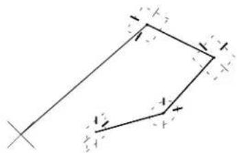
natural_image
Pure geometric diagram of a parallelogram with directional arrows, no text or symbols presentYou can override this feature via the AccuDraw Settings dialog box (Operation tab section: Context Sensitivity check box off) in which case, the compass maintains the traditional view axes
3-34 MicroStation User Guide
orientation (+X to the right, +Y straight up).
Drawing plane coordinate systems
AccuDraw's drawing plane supports two different coordinate systems. This echoes MicroStation's normal support for rectangular and polar coordinate values:
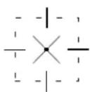
- Rectangular, for specifying distances along the drawing plane axes. AccuDraw's frame appears as a square indicator.
- Polar, for specifying distances and angles relative to the origin. AccuDraw's frame appears as a circular indicator.
To switch between Rectangular and Polar coordinate systems
- With the focus in the AccuDraw window, press
.
Alternative method — To switch between Rectangular and Polar coordinate systems
- With AccuDraw active, open the AccuDraw Settings dialog box by pressing G followed by S (Get Settings).
or Choose Settings > AccuDraw.
The AccuDraw Settings dialog box opens.
- Click the Coordinates tab.
- From the Type option menu, choose Polar or Rectangular.
The AccuDraw window
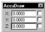
AccuDraw has its own window, named AccuDraw, which contains the data entry fields and axis lock buttons for the currently active coordinate system.
AccuDraw's window and the input focus
When AccuDraw is active it becomes part of the input focus order controlled by the Esc key. The focus order toggles between the AccuDraw window and the Tool Settings window unless the Key-in window is open. In this case, the input focus cycles from the AccuDraw window through the Tool Settings window to the Key-in window. Pressing Shift-Esc reverses the cycle, moving the focus from the Key-in window through the Tool Settings window to the AccuDraw window.
This is important to remember as no AccuDraw shortcut key-in works unless focus is in the AccuDraw window. Fortunately, after every data point or tentative point, the focus is forced to the AccuDraw window where it remains until you press the Esc key.
The AccuDraw window initially comes up floating just like any other window. However, it can be docked to either the top or bottom edge of the MicroStation application window.
AccuDraw window docked along the bottom edge of the application window.
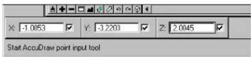
text_image
X: -1.0053 Y: -3.2203 Z: 2.0045 Start AccuDraw point input toolDocking the AccuDraw window has the advantage of minimizing its intrusion into the working area of your drawing. As with the floating window version, the fields found in the docked version
change depending on whether you are in polar or rectangular mode and whether you are in a 2D or 3D DGN file.
AccuDraw's Settings dialog box
Many aspects of AccuDraw's behavior are specified using the controls in the AccuDraw Settings dialog box. A few have already been mentioned (such as context sensitivity, and axis display colors).
To open the AccuDraw Settings dialog box
- From the Settings menu, choose AccuDraw.
or
With the focus in the AccuDraw window, press G , S .
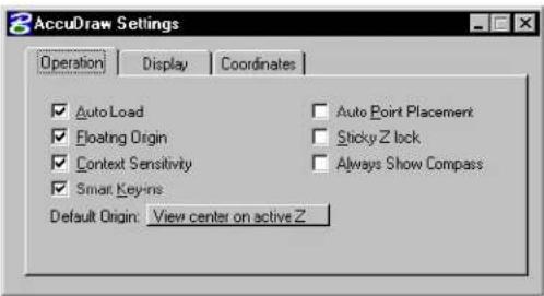
text_image
AccuDraw Settings Operation Display Coordinates ✓ Auto Load ✓ Auto Point Placement ✓ Floating Origin ✓ Sticky Z lock ✓ Context Sensitivity ✓ Always Show Compass ✓ Smart Key-Ins Default Origin: View center on active Z
For information about other AccuDraw settings not covered elsewhere in this chapter, see "AccuDraw" in the online Reference Guide.
Controlling and using AccuDraw
AccuDraw is controlled from a variety of sources. You can influence it through the use of one- and two-key sequences called shortcut key-ins. Drawing tools, themselves, can influence AccuDraw's operation. Finally, AccuDraw itself maintains a number of user selectable options via the AccuDraw Settings dialog box.
AccuDraw supports a large number of options, all of which can be placed into one of three major AccuDraw functions:
- Previewing and constraining data points
- Locating the AccuDraw compass
- Orienting AccuDraw's drawing plane
The following discussion is organized along these three basic operations. In most instances, you will use a combination of all three types of AccuDraw operations to accomplish your design goal.
AccuDraw may be employed in a variety of different situations — with standard drawing and manipulation tools, or using more advanced approaches, such as with the Place SmartLine (see page 2-17) tool and the Modify Element tool (see page 4-90). In either case, AccuDraw employs the same general procedure:
- Select the desired tool.
- Enter a data point to activate dynamics and set the location of the drawing plane origin. See "The origin point" on page 3-32.
- If necessary, rotate the drawing plane axes. See "AccuDraw's drawing plane orientation" on page 3-62.
- If necessary, set the type of drawing plane coordinate system. See "Drawing plane coordinate systems" on page 3-35.
- Preview and constrain the next data point. See "Previewing and constraining data points" on page 3-39.
- Enter the data point.
Typically, you will use a mix of AccuDraw options throughout the design process. The key to working with AccuDraw is understanding how it interacts with the active tool and the current data point.

Many drawing tools are optimized for use with AccuDraw. See "AccuDraw's Effect on Various Tools" on page 3-67.

AccuDraw is particularly useful when employed in 3D.
Previewing and constraining data points
AccuDraw, via tentative points, lets you preview and constrain pending data point locations. In response to your input in the AccuDraw window, dynamic update in view windows lets you visualize the results. This gives you the option of accepting the displayed tentative point, or trying another location. That is, you have the flexibility to unconstrain a pending data point at any time. It is only when you actually enter a data point that you are committed to the values in the AccuDraw window and their results.
How AccuDraw reacts to pointer movement
When active, AccuDraw reacts to pointer movement by trying to anticipate your intent.
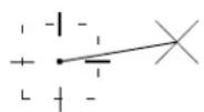
As you move the pointer, the fields in the AccuDraw window automatically update to reflect the drawing plane coordinates of the current pointer location (expressed as either relative x, y, and z offsets, or as a distance and an angle) with respect to the location of the AccuDraw compass.
Furthermore, the AccuDraw window's input focus automatically adjusts, based on the general direction of the pointer movement. As you move the pointer in the same direction as either drawing plane axis the focus moves to the field that you would use to precisely locate the data point along that axis.
Tolerance setting
In the Coordinates tab section of the AccuDraw Settings dialog box is a setting for indexing tolerance for both Axis and Distance (instead of using Locate Tolerance (see page 3-11) from the Workspace > Preferences dialog box — although, by default, they are the same: 10 pixels). Alternatively, you can set this with a key-in (and therefore a shortcut or function key): ACCUDRAW SETTINGS INDEXTOL [NUM], where [num] is the number of pixels ranging from 1 to 100. This is useful when you want to do detailed work without it getting pulled back to the axes or to the last distance.
When the pointer is within the Tolerance of an axis, of the displayed AccuDraw compass, then the pointer snaps to the alignment of that axis. At this point, the dynamic element is considered indexed to that axis. Similarly, if the pointer is within the Tolerance of the previous distance, the pointer snaps to that distance.
Index highlight along a drawing plane axis.
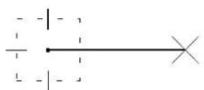
natural_image
Pure electrical circuit lines without any symbolsThe effect of these behaviors is to make it as easy as possible for you to apply constraints and specify precision when previewing a data point.
To enter rectangular coordinates using AccuDraw
- Enter the first data point.
As you move the dynamic line, AccuDraw shifts its key-in focus to the X or Y field depending on which axis the pointer is closest to. (If the Polar compass is visible, press
- When the focus is on the X field, type the desired X value. AccuDraw automatically locks this value in, denoted by the
check mark in the box adjacent to the X field.
Keying in a precise distance along the x-axis.
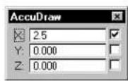
- Move the pointer up the Y axis. Notice the dynamic dashed line identifying the locked condition from the X axis.
The distance required to move the pointer to change focus to the Y field is the same as the Locate Tolerance (see page 3-11) associated with identifying an element and is selectable in the Coordinates tab of the AccuDraw Settings dialog box.
- Type the Y value desired (press Enter to complete the input).
AccuDraw responds by setting the endpoint of the new element and displays fixed, dashed lines extending to the point from the X and Y axes of the compass.
- Enter a data point to accept the location.
If you do not want to accept this point, press Enter to override the locked axes and return the pointer to the free dynamic state.
When working with Polar coordinates, AccuDraw does not automatically shift the focus from the Distance and Angle fields like it does with the X and Y fields in Rectangular coordinates. Instead, you must navigate between these two fields to enter precise values. This is easily done using the Tab or down arrow keys.
When it comes to entering angular values, however, AccuDraw does try to help you out by not requiring a negative value when you want to go off in the "opposite" direction from an axis. Simply by moving the pointer to the opposite quadrant from the positive angle, AccuDraw moves the dynamic element in the negative direction.
ToenterapolarcoordinateusingAccuDraw
- Enter the first data point.
If the Rectangular compass appears, press the space bar to switch to Polar coordinates.
- Type a distance value in the Distance field. If the input focus is on the Angle field press the Tab or down arrow key first.
AccuDraw will lock the length of the dynamic element to this value. You can rotate this dynamic element around.
- Press the Tab or down arrow key.
The input focus will shift to the Angle field.
- Type the desired angle or
Press the(A) key to lock in the angle at the current pointer location.
- Enter a data point to accept the coordinate entry.
Previous distance recall
Another example of how AccuDraw tries to help you is its previous distance feature. As you place elements in your model, AccuDraw keeps track of the distance between your last two data points. Known as the Previous Distance, AccuDraw uses this distance as a hint for your next data point.
Think of previous distance as a radius length from the compass origin. When you move the pointer within the Tolerance (see "Locate Tolerance" on page 3-11) distance to this radius, AccuDraw displays a small tangent line called the previous distance indicator, and locks the pointer to this point.
Previous distance indicator.
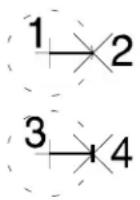
As you keep the pointer within the Tolerance (see “Tolerance setting” on page 3-40) distance of this previous distance, AccuDraw will keep it locked. This, of course, only works with Polar coordinates. If you are using Rectangular coordinates, the previous distance only works when you are indexed to either drawing plane axis.
A data point will result in an offset distance from your last data point precisely the same as the distance between your previous two data points.
This “lock” on feature is not hard to override. Just continue dragging the pointer until it is outside the Tolerance and the previous distance lock disengages.
Recalling previous values
AccuDraw stores all entered values for its X, Y, Distance, and Angle fields for recall as needed. When in the X, Y, (Z in 3D), Distance, or Angle fields, pressing the PgUp key recalls the last distance or angle value entered in any of these fields. Pressing PgUp again recalls the next to last entered value and so on. You should note that the X, Y, Z, and Distance fields share a common value buffer but that Angular data is stored separately. This means you can enter a value in the X field, for instance, change the input focus to Y, and by pressing PgUp , enter the same value as placed in the X field.
Settings manipulation
Several AccuDraw settings that can be set in the AccuDraw
Settings dialog box also can be toggled on or off with key-in commands. For instance, to turn on context sensitivity, you can key in: ACCUDRAW SETTINGS CONTEXTSENS ON. If you enter it without trailing "on" or "off," it behaves as a toggle. Being able to turn settings on or off is most useful for such things as macros, although you may want them as toggles in a function key/shortcut. These key-ins apply also to autoload, floating origin, auto point placement, axis indexing and distance indexing.

The on/off option does not show up in the Key-in window
AccuDraw and the Popup Calculator
With the pop-up calculator, you can perform mathematical operations on the values displayed in some MicroStation text fields and the values adjust accordingly.

This feature is documented here as it works with AccuDraw. In fact, its use is extendable to other controls. For example, Active Scale and Active Angle fields currently support it. The pop-up calculator is supported as follows:
| Dialog Box Fields | |
| AccuDraw window X | YZDistanceAngle |
| (various) Active Angle | |
| (various) Active Scale |
To use the pop-up calculator
- With the input focus in a field that supports pop-up
calculation, = type = any = of = the = following:
$$ +, = -, = ^ {*}, = /, = = $$
2.=Type=a=value=or=expression=to=complete=the=calculation.
Press
Generating a calculated value (by typing "2+1").
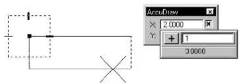
text_image
AccuDraw X: 2.0000 Y: + 1 30000Performing simple operations
The=pop-up=calculator=lets=you=perform=calculations=on=measured values=(snap=to=an=element,=then=multiply=the=distance,=for=example), or to=simply=type=in=the=entire=equation,=such=as="5.23+=1.34."
Not=only=does=the=pop-up=calculator=eliminate=the=need=to=use a=physical=calculator, =you=may=notice=that=with=the="+"=and="-" operations, =you=do=not=have=to=reposition=AccuDraw's=origin=to move=relative=to=a=snapped=or=keyed-in=offset.
The=calculator=is=designed=to=be=very=efficient,=to=work=seamlessly with=AccuDraw,=and=to=be=entirely="keyboard-driven,"=letting=you keep=the=mouse=in=the=view=window=rather=than=having=to=click in=the=dialog=box.=Also,=the=calculator=works=in=a="per-keystroke" manner==the=result[of=the=calculation=is=expressed=both=numerically and=graphically=with=every=keystroke=typed.
The=pop-up=calculator=is="format=aware,"=as=it=accepts=expressions in=feet=and=inches=or=degrees-minutes-seconds,=if=appropriate. Obviously=you=cannot=multiply=feet=times=feet,=so=the=calculator
properly adjusts to interpret this type of string.
When performing operations on a measured value, the pop-up calculator always operates on the underlying precise value, rather than the string which is truncated to whatever coordinate readout you have. This dynamic value displays at the bottom of the pop-up calculator.
Creating a relative offset (by snapping then typing “+2” when the X field has input focus).
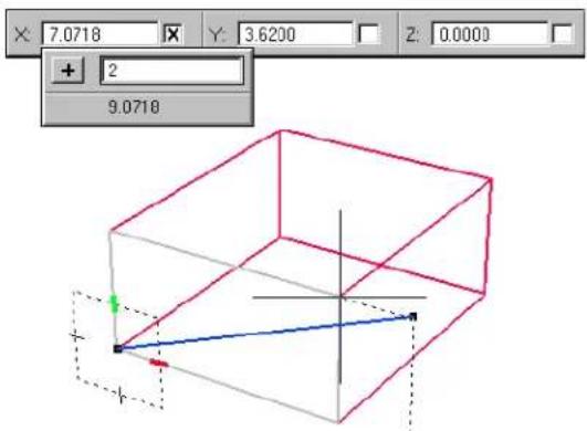
text_image
7.0718 Y: 3.6200 Z: 0.0000 + 2 9.0718
You may notice that sometimes pressing +, -, or / does not bring up the calculator, but is interpreted by AccuDraw as either an explicit positive or negative, or as a fraction. The rule with the “+” and “-” operators is: If the value is locked or a tentative point is active, the calculator displays. If you type something like “3 3/8,” the “/” is interpreted as part of a fraction because of the space. If you simply type “3/8,” AccuDraw uses the calculator but the result will be the same as 3 divided by 8, or the fraction 3/8. To enter “1 foot and 3/8 inches” you must type a space (“1: 3/8”) so the value is not misinterpreted as “1 foot 3 inches, divided by 8.” “1+:3/8” would also work.
When entering planar data points (not polar coordinates), there are some special procedures to prevent unexpected results. Since AccuDraw interprets values as negative when the cursor is pointed in the negative direction, the calculator, when appropriate, prepends the entered expression with a minus sign.
Advanced uses of the pop-up calculator
You=can=use=the=pop-up=calculator=to=enter=complex=expressions, including=multiple=operators,=parentheses,=and=C=expressions ("sin(30)",="tcb->actangle"). Parentheses=do=not=have=to=be matched=to=have=a-valid=string.
If you type =, the pop-up calculator replaces the existing AccuDraw value=rather=than=operating=upon it.=In=this=case=the=result dynamically=updates=in=the=original=field,=rather=than=having=a field[of=its=own=on=the=pop-up.=This=is=rarely=needed=for=simple operations,=but=can=be=useful=for=complex=expressions.
Yo u can u set h e compact popup
to replace values with expressions that do not contain a simple operator.
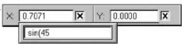
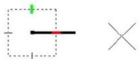
You=can=also=enter=and=save=variables.=Although-you=cannot
save=them=to=a=file,=and=there=is=no=graphical=user=interface,=this
functionality=can=still=be=exceptionally=useful.=By=default,=the=only
saved=variable=is="pi."=The=variable=can=then=be=entered=within=any
expression=using=the=calculator.=To=use=the=variable=directly=as
a=distance=or=angle,=type="=
Entering a complex expression including parentheses and a user-defined variable.
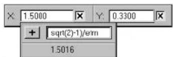
text_image
× 1.5000 Y: 0.3300 + sqrt(2)-1)/e/m 1.5016To save variables
1.=Type="popcalc=variable=save=
The=value=may=be=entered=as=a=complex=expression,=if=desired.=The value=is=optional;=if=none=is=supplied,=it=uses=the=last=value=used=by the=calculator=(thus=allowing=the=use=of=measured=values).
To show variables
1.=Type="popcalc=variable=show=name."
The= name= is= optional;= if= none= is= supplied,= all= variables= print= to a=Messages=dialog=box.=Where=a=variable=name=is=supplied, its=name=and=value=appear=in=the=status=bar.
To delete variables
1.=Type="popcalc=variable=delete=name."
Finally, =there=is=a=special=variable,="\,"=that=represents=the=starting value, =whether=measured=or=typed=into=AccuDraw's=field.=For instance, if =you=measure=a=distance=with=AccuDraw=and=then want=one=over=that=distance, =you=can=simply=type="1/\."=Or, =for example, =to=get=12=squared, =type="12*\$.
AccuDraw's shortcut key-ins
Although=AccuDraw=tries=to=anticipate=your=next=move=it=cannot always=predict=your=intentions.=AccuDraw=therefore=includes=a=wide variety=of=single=and=double=character=command=directives=known=as the=shortcut=key-ins.=By=pressing=the=appropriate=key,=you=can=direct AccuDraw=to=perform=a=specific=target.=In=operation,=AccuDraw=is=the default=input:focus=in=most=cases,=thus=letting_you=just=type=in=the shortcut=without=having=to=consider=where=the=input:focus=is.
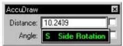
Pop-ups confirm single letter shortcuts below the focused input field. This function is not only useful to confirm the key-in, but also it serves to communicate that the shortcut is received via AccuDraw's input fields.
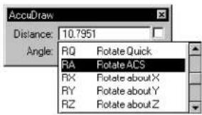
text_image
AccuDraw Distance: 10.7951 Angle: RQ Rotate Quick RA Rotate ACS RX Rotate about X RY Rotate about Y RZ Rotate about ZTwo letter shortcuts appear attached to the focused input field, and confirm the action through the temporary appearance of the AccuDraw Shortcuts window. The pop-down list adjacent to the input field illustrates where the shortcut comes from, thereby making it easy to “follow the action.”
The following is a list of the more common shortcut key-ins:
For the complete list, see "Complete List of AccuDraw Keyboard Shortcuts" on page 3-73.
| Key | Effect |
| ? | Opens the AccuDraw Shortcuts window. |
| Smart LockIn Rectangular coordinates,lockxXto0ifthepointethe drawing plane y-axis or Y to0 if the pointer is on the x-axis.In Polar coordinates, locks Angleto,θ0°, -90°, or 180° if the pointer is on a drawing plane axis or otherwise locks Distance to its last entered value. | |
| Switches between Rectangular and Polar coordinates. | |
| Moves the drawing plane origin to the current pointer position. This can also be used to explicitly activate AccuDraw before you enter a data point. | |
| X | Toggles the lock status for the X value. |
| Y | Toggles the lock status for the Y value. |
| D | Toggles the lock status for the Distance value. |
| A | Toggles the lock status for the Angle value. |
AccuDraw defaults
There is a command to set the shortcuts back to the defaults, and one to reread the shortcuts file. The latter is useful if you want to change the file manually without exiting MicroStation. It could be useful, also, if you would like to alter the shortcuts programmatically (for example, with MDL or BASIC). Key-ins to perform these tasks are: ACCUDRAW SHORTCUTS DEFAULTand ACCUDRAW SHORTCUTS READFILE.
Create, edit and delete shortcuts
As well as being able to edit the input fields in the AccuDraw window, you can create, edit, and delete, shortcuts in the AccuDraw Shortcuts window. In brief, you can:
- Press Delete in any of the text fields in the AccuDraw window, which will let you edit, or delete, the string.
- Delete a shortcut by highlighting it in the AccuDraw Shortcuts window and pressing Delete.
- Create a new shortcut. When you do this, it will be inserted following the highlighted one, rather than being put at the end of the list.
- Edit an existing shortcut.
When you create a new shortcut, or edit an existing one, a message box appears informing you if the shortcut is a duplicate or conflicts with an existing one (for instance, F and FS). You still can create it if you want to, which often is convenient if you want to edit the other one later, but if you click No, it returns you to the Edit/New Shortcut dialog box. If, for some reason, your edited shortcuts cannot be written to the "shortcut.txt" file, an error message will warn you of the situation.
General Procedure — To activate a shortcut key-in
- With the focus in the AccuDraw window, simply press the keyboard key(s) that corresponds to the shortcut you wish to use.
If the first typed letter is, by itself, a valid shortcut, the shortcut activates.
Otherwise, the AccuDraw Shortcuts window opens. The window lists the available shortcuts. Typing the second letter activates the shortcut.
To review a listing of the available AccuDraw shortcuts
- With the focus in the AccuDraw window, press the ? key.
The AccuDraw Shortcuts window opens.
AccuDraw Shortcuts window
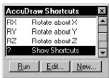
To activate a single-letter shortcut from the AccuDraw Shortcuts window
- In the list box, select the desired shortcut and click the Run button. or Press the key that corresponds to the desired shortcut.
To activate a two-letter shortcut from the AccuDraw Shortcuts window
- In the list box, select the desired shortcut and click the Run button. or Press the two letters that correspond to the desired shortcut.
Smart Lock
One of the first keyboard shortcuts you will use is Smart Lock. Similar in operation to striking a line along a T-square, Smart Lock is invoked by pressing the Return key. Depending on where the pointer is located, at the time you select Smart Lock, one of two things will occur:
- If the pointer is oriented closer to the X axis of the compass, the pointer will lock to the X axis.
- If the pointer is oriented closer to the Y axis of the compass, the pointer will lock to the Y axis.
You know the pointer is locked on an axis when the dynamic line highlights. Pressing the Return key again deactivates Smart Lock and releases the dynamic line back to free motion.
To constraint the pending datapoint to a drawing plane axis
- Position the pointer near the desired axis. When the pointer is on an axis, a highlighted line is displayed from the drawing plane origin to the pointer location.
Positioning the pointer on a drawing plane axis — the x-axis (above), on the y-axis (below).
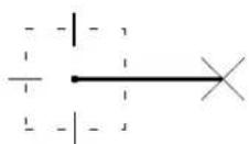
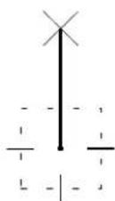
- Press the Return key.
Smart Lock is engaged. Its effect is to constrain the pending data point to the axis.
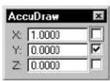
Constraining the pending data point along x-axis.
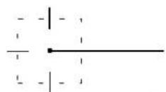
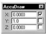
Constraining the pending data point along y-axis.
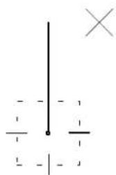
natural_image
Pure electrical circuit lines without any symbolsYou now can constrain the pending data point to a precise distance along the axis by keying in a value, or simply by snapping a tentative point to an element or monument point and accepting the tentative point as the data point location.

To disengage Smart Lock and unconstrain the pending data point, press Return again. The Return key toggles Smart Lock.
Snapping to constrain the pending data point to a precise distance along the x-axis.
text_image
2
Smart Lock will not lock to an axis when you are entering coordinate values into its field. Instead, AccuDraw returns the dynamic element to free motion.
X and Y l o c k s
When using the Rectangular coordinate system, you can force AccuDraw to lock the current distance along an axis by activating the X or Y keyboard shortcut. AccuDraw responds by locking the dynamic line to the chosen axis at the current pointer distance from the origin point of the compass. Having done this, the focus of the complement AccuDraw axis data field becomes the focus for your next keyboard entry.

AccuDraw automatically switches its coordinate system to rectangular in response to the X or Y lock. All X and Y values entered are relative to the plane of the previous element segment.
To override this, AccuDraw provides an option in its settings called Context Sensitivity. Turning this off forces AccuDraw to stay oriented to the DGN file's XY axes.
Distance lock
Youcanuse the D shortcut to lock the distance from the compass origin point to the current location of the pointer and, if necessary, change AccuDraw's coordinate system to Polar. The input focus automatically shifts to the Angle field.
To interactively enter the distance of the dynamic element
- In the AccuDraw window's Distance field (Polar coordinates), type the distance.
Automatically, the pending data point is constrained, as indicated by the check box next to the Distance field. Dynamic update occurs in response to each keystroke.
Alternative method — To interactively enter the distance of the dynamic element
-
Move the pointer away from the drawing plane origin until the desired distance is displayed in the AccuDraw window's Distance field. As the pointer is moved, the displayed distance is rounded off to the increment specified by the Unit Roundoff's Distance setting (if the setting is turned on) in the Coordinates tab section of the AccuDraw Settings dialog box.
-
Press the D key.
Angle lock
You can use the A shortcut to set the angle portion of the polar drawing plane and, if necessary, change AccuDraw's coordinate system to Polar. AccuDraw sets the angle to the current position of the pointer.
To interactively lock the angle of a dynamic element
- In the AccuDraw window's Angle field (Polar coordinates), type the angle, in degrees.
Automatically, the pending data point is constrained, as indicated by the check box next to the Angle field. Dynamic update occurs in response to each keystroke.
Alternative method — To interactively lock the angle of a dynamic element
- Move the pointer around the drawing plane origin until the desired angle is displayed in the AccuDraw window's Angle field. As the pointer is moved, the displayed angle is rounded off to the increment specified by the Unit Roundoff's Angle setting (if the setting is turned on) in the Coordinates tab
section of the AccuDraw Settings dialog box.
- Press the A key.

The Angle value automatically switches to the "opposite" angle if the pointer position dictates.
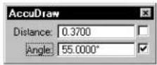
Angle value automatically switches to the "opposite" value.
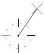
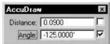
Angle value automatically switches to the "opposite" value.
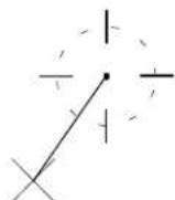
Unit roundoffs and their effect on AccuDraw
Although you can set the X, Y, Z, Distance, and Angle fields by typing in values, AccuDraw also supports a roundoff feature that can force the new data point to a multiple of a set value. You can set AccuDraw's Unit Roundoff in the Coordinates tab section of the AccuDraw Settings dialog box.
Distance roundoff
When you enable the Distance field in Unit Roundoff, AccuDraw acts as if there is an invisible grid in effect. The Distance Roundoff, however, always is calculated from the current compass location. In addition, at any time you can override this value by snapping to an element, or entering a value in the X, Y, Z, or Distance fields of the AccuDraw window.
To round off the values displayed in AccuDraw's X, Y, Z, and Distance fields as the pointer moves
- In the AccuDraw Settings dialog box, click the Coordinates tab.
- In the Unit Roundoff section, turn on Distance.
- In the Distance field, key in the desired increment.
To cancel distance roundoff
- In the AccuDraw Settings dialog box, click the Coordinates tab.
- In the Unit Roundoff section, turn off Distance.
Angle roundoff
You can use the Angle Unit Roundoff to lock elements along specific axes. For instance, setting the Angle Roundoff to 30 degrees assures that all elements placed will occur along one of the normal isometric drawing axes. As with the X, Y, Z, or Distance fields, at any time you can override this value by snapping to an element, or entering a value in the Angle field of the AccuDraw window.
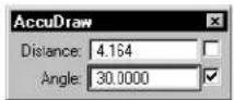
Drawing in progress showing AccuDraw window with angle locked to 30.

To round off the values displayed in the AccuDraw's Angle field as the pointer moves
- In the AccuDraw Settings dialog box, click the Coordinates tab.
- In the Unit Roundoff section, turn on Angle.
- In the Angle field, key in the desired increment in degrees.
To cancel angle roundoff
- In the AccuDraw Settings dialog box, click the Coordinates tab.
- In the Unit Roundoff section, turn off Angle.
Moving the AccuDraw compass
By default, AccuDraw places its compass at the last data point location. There are, however, times when you need to take over control of the AccuDraw compass. Tentative point operations can take better advantage of AccuDraw's capabilities when you "unlock" the compass and place it wherever needed. The following covers how you do this and some interesting ways in which you can use AccuDraw to accomplish otherwise difficult operations.
The floating origin option
At any time, you can move AccuDraw's compass to the pointer location. You do this with the "O" keyboard shortcut, which forces AccuDraw to move the compass to the current pointer location.
This occurs regardless of the tool or operation currently selected. This last point is important to recognize. AccuDraw is considered a non-modal feature in that you don't have to be in a predetermined part of a procedure in order for it to operate.
In practice, the most common use for a relocated compass origin point is to index the element under construction from an existing point. For instance, if you want to locate the corner of a block a specified distance from a given location, you can tentative snap to the given location, then press O to move the drawing plane origin to the snap. From there you can use AccuDraw to position the tentative point from this relocated origin point. This procedure is explained in the following section on AccuDraw and the tentative point.
AccuDraw and the tentative point
Creating precision offsets is a fundamental function of the design process. AccuDraw performs this important function by utilizing tentative points. These can be input manually, or you can further streamline the process using AccuSnap.
Whether you use AccuSnap or manually entered tentative points, the key to using AccuDraw and the tentative point is the Set Origin function (the O shortcut key-in). When there is a tentative point present, pressing the O key results in the relocation of the compass to the tentative point location.
AccuDraw enters a dynamic tentative point mode where you can manipulate the final data point location as follows:
- Enter coordinate data using the AccuDraw window.
- Use a second tentative point and various locks (X/Y or D/A) to interactively set the offset.
This latter technique is useful when you need to set an offset from two elements.
To create an offset from an element, along the X or Y axis
- With a tool active, use AccuSnap to display a tentative point at the required point on the element (or place it manually).
- Press the O shortcut key.
The compass moves to the tentative point location. - Move the pointer so that it is indexed on the required X or Y axis.
This sets the focus automatically to the indexed axis. - Key in the required distance.
- With the pointer still indexed to the axis, accept with a data point.
To create an offset from an element, along both X and Y axes
- With a tool active, use AccuSnap to display a tentative point at the required point on the element (or place it manually).
- Press the O shortcut key.
The compass moves to the tentative point location. - Move the pointer so that it is indexed on the required X or Y axis.
This sets the focus automatically to the indexed axis. - Key in the required distance.
This locks the distance on the indexed axis. - Move the pointer along the other axis, and note that a dashed line indicates that the distance from the first axis is maintained.
- Key in the required distance along the second axis.
Dashed lines indicate the distances from the X and Y axes. - Accept to place the data point at the offsets.
To create an offset from two elements
- With a tool active, use AccuSnap to display a tentative point at the
keypoint of the first element (or place it manually).
- Press the O shortcut key.
The compass moves to the tentative point location.
-
On the keypoint of the second element, use AccuSnap to display a tentative point (or place it manually).
-
Press the X or Y key.
AccuDraw responds by locking the dynamic line to the appropriate X or Y axis, but at the offset from the first tentative point to the second one.
- Use another tentative point to "lock" the remaining axis of the tentative compass location.
or Enter a data point to set the second axis value.
AccuDraw relocates the initial compass to the new indirectly derived location. From here you can continue the use of the current drawing tool.
AccuDraw's drawing plane orientation
AccuDraw is a powerful tool in 2D drafting. It is even more powerful in 3D design, where you can work in a known coordinate system even though the view has a different orientation. For example, you can work in an Isometric view, with the AccuDraw drawing plane oriented in the Top View. AccuDraw orients the drawing plane in accordance with the Coordinate System Rotation setting in the AccuDraw Settings dialog box:
| Coordinate System Rotation | Definition |
| Top (default)Orients | compass to match top view (in 2D same as an unrotated view). |
| Front | Orients compass to match front view (3D only). |
| Side | Orients compass to match side view (3D only). |
| View | Orients compass to current view axes. |
| Auxiliary Orients | compass to last defined auxiliary coordinate system (see Rotate Auxiliary). |
| Context A temporary or ientation affected by a number of factors including the current tool, the previous data points and the “RQ” keyboard shortcut. | |
Rotating the drawing plane axes in 2D
Along with the standard drawing plane orientations, the rotation of the drawing plane axes can be altered using keyboard shortcuts. In 2D, you are limited to rotating AccuDraw's drawing plane about the view axis. This matches the same restriction placed on rotating views in 2D.
Rotation-sensitive tools
Depending on the tool in use, dynamically rotating the drawing plane axes yields slightly different results. For example, consider the scenario of placing a block (rectangle) with the Place Block (Orthogonal) tool (see page 2-44), which takes its orientation from the drawing plane XY axes.
Once the drawing plane axes are rotated, the block's main axis is constrained to the rotated XY axis.
Contrast this to the effect when using the Place Line tool (see page 2-23): The drawing plane axes rotate, and while dynamic readout is a function of the newly rotated system, the tool itself remains available to dynamically place the line wherever desired.
The Rotate Quick Shortcut Key-in
You can use the Rotate Quick ( R , Q ) shortcut to change the orientation of the drawing plane only for the current data point, after which it resumes its normal orientation. This will vary, depending on the tool being used.
To quickly rotate the drawing plane axes
- With AccuDraw dynamics active, press R , Q
The drawing plane indicator spins freely about its origin, the x-axis following the movement of the screen pointer.
- Enter a data point to accept the specified rotation.
The use of the previously selected tool continues.
Forexample, suppose you are using the Place Line tool (see page 2-23) to start a construction and wish to align the drawing plane axes with the new line. After establishing the drawing plane origin (with the first data point of the line), pressing R , Q lets you rotate the drawing plane axes interactively.
Dynamically rotating the drawing plane axes.
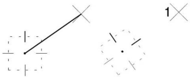
text_image
Diagram showing a diagonal line intersecting two dashed circles with cross symbols, labeled '1' in the corner.Placing the line.
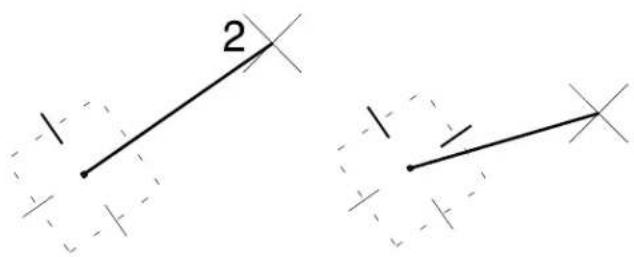
text_image
2
Shortcut key-ins are available to rotate the drawing plane coordinate system 90° about an individual axis "RZ" (plus "RX" and "RY" in 3D) or to align it with the design plane axes "T" (plus "F" and "S" in 3D) or view axes "V". When working in a 3D environment, AccuDraw's axes rotation takes on a very important role in the design process. This is discussed in Using AccuDraw in 3D (see page 8-59).
Using shortcut snap modes with AccuDraw
AccuDraw provides a few keyboard shortcuts to enhance popular tentative point snaps:
• "N" — Nearest
• “C” — Center
• “T” — Intersect
These shortcuts work the same as selecting the snap from the status bar or Snap Mode button bar, with the exception of Nearest.
The AccuDraw-enhanced Nearest snap mode
With AccuDraw disabled, when you snap to an element with the Nearest snap, either manually or with AccuSnap, MicroStation enters the tentative point at the point on the element closest to the pointer. With AccuDraw active, this changes a bit. When the
pointer is constrained by either X, Y, Distance, or Angle Lock, and an element is snapped using Nearest snap mode, AccuDraw will attempt to produce a tentative point at the nearest point on the element that also satisfies AccuDraw's lock.
In many cases the effect is similar to that when using the Extend Element to Intersection tool (see page 4-105). In the case where there is no point on the snapped element that satisfies AccuDraw's lock, the snapped point will simply appear at the point on the element closest to the pointer. This point will then be projected onto the hypothetical line or circle determined by AccuDraw's lock.
Nearest snap with Place SmartLine tool constrained by an angle.
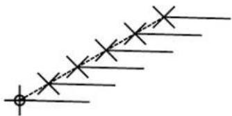
natural_image
Pure electrical circuit lines without any symbolsSetting the keypoint snap divisor
Although not technically a snap mode, there is one additional shortcut associated with tentative point snaps, "K" which opens the Keypoint Snap Divisor dialog box. This lets you define the number of keypoints in each element. When you use this shortcut, the following snap point is a Keypoint snap.
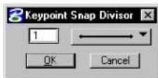
AccuDraw's Effect on Various Tools
Although much of AccuDraw's operation is global in nature, it does have subtle effects on individual tools. As you learn to use AccuDraw you will find that it can be used as a substitute for many individual tool settings. The following discussion provides some insights into this feature.
The Place SmartLine tool is specially designed to exploit AccuDraw's capabilities. See "AccuDraw and the Place SmartLine Tool" on page 3-70.
AccuDraw and the Place Circle tool
A simple tool like Place Circle (see page 2-36) can benefit from AccuDraw in a number of ways. First, when you place a circle you can explicitly set the diameter of the circle by turning on the Diameter tool setting and entering a value. However, with AccuDraw active this can be done with fewer keystrokes.
Once you've placed the circle's origin point all you have to do is type in the radius value. AccuDraw automatically locks the circle to the value indicated by the locked dynamic circle. It really doesn't matter which drawing coordinate system is active.
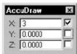
Using AccuDraw to place a circle by center.
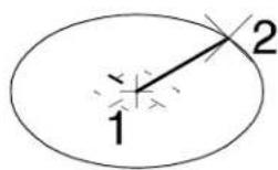
To place a second circle of equal radius is also easy. Using AccuDraw's previous distance feature, when you move the pointer away from the center data point, the circle will temporarily lock to the previous radius letting you enter the second data point. This does require two data points for all remaining circles, so if you are placing numerous fixed diameter circles you may want to use the Diameter tool setting.
AccuDraw and the Place Arc tool
AccuDraw can be used to simplify the operation of the Place Arc (see page 2-67) tool. By using the polar coordinate system you can easily specify radial lengths and sweep angles just by typing them in via AccuDraw.
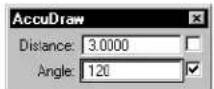
Using AccuD-raw to place an arc by center.
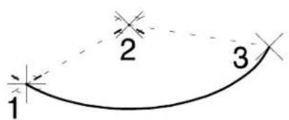
text_image
1 2 3This is one case where AccuDraw's context sensitive orientation is good for incremental angle settings, and View or other rotations are good for setting an absolute sweep angle.
AccuDraw and the Place Ellipse tool
When you place an ellipse without AccuDraw you specify a center point, the primary axis and radius, and a point through which the ellipse will pass. You can do this by selecting the various options in the Tool Settings window or use AccuDraw to set these values in a more user-friendly manner.
When you enter that first center point, AccuDraw's effect becomes noticeable. The second data point still defines the major axis, but now you can specify both the radius and angle using the AccuDraw window simply by entering the radius and angle or dynamically positioning it.
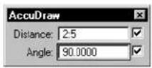
Using AccuD-raw to place an ellipse by center and edge.
text_image
1 2 3Now, because the AccuDraw compass orients itself along the axis of the ellipse under construction, the secondary axis is automatically locked so you can simply enter the value or position the pointer and data point.
AccuDraw and the Place Block tool
You can use AccuDraw with the Place Block tool to place a block with specific dimensions and at a specific angle.
With the Rotated method you can specify the angle and X length of the block using the polar drawing plane. Once the base of the block has been defined, AccuDraw orients the compass along this base. At this point, you can switch to rectangular mode (space bar) and
lock in the Y distance by simply entering its dimension.
Using AccuD- raw to place a block.
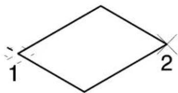
text_image
1 2AccuDraw and the Place SmartLine Tool
The Place SmartLine tool (see page 2-17) is used to automatically place a complex chain or shape containing a dynamically specified collection of segments and vertices. This tool is designed to be used in conjunction with AccuDraw. The main benefits of using AccuDraw with Place SmartLine are as follows:
• The drawing plane origin automatically moves to the location of a newly defined vertex.
- The drawing plane automatically rotates to align with a newly defined segment. This allows tangent and perpendicular segments to be easily defined.
- When defining an arc segment, the drawing plane coordinate system automatically switches to Polar.
To define an arc segment tangent to the previous segment
- With AccuDraw active and Place SmartLine selected, and Segment Type set to Lines place two data points to define a straight section. Note that AccuDraw aligns its
drawing plane with the line segment.
- Now, set Segment Type to Arcs.
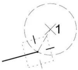
text_image
1 -1 1Switching
the Place
SmartLine
Segment Type
to Arcs.
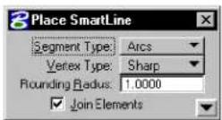
- Move the pointer toward the drawing plane axis that is perpendicular (that is, at 90^ ) to the previous segment.
When the pointer is close to the axis, the arc radius position dynamically aligns with it.
Defining the center point.

text_image
2- With the pointer indexed to the axis, enter a data point to define the center point for the arc.
The drawing plane coordinate system automatically switches to Polar, and the arc's center point and sweep angle are dynamically displayed.
- Enter a data point to define the arc's sweep angle and complete the segment definition.
Defining the sweep angle.
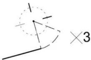
text_image
×3
You can key in values for the Radius and the sweep angle, using AccuDraw's input fields. As well, the arc's sweep angle can be defined in either direction — clockwise or counterclockwise.
AccuDraw affects most tools
The tools just described were selected to illustrate how AccuDraw works with even the simplest tools to provide additional capabilities, or easier access to options, over non-AccuDraw operations. AccuDraw actually affects the operation of most MicroStation tools, and even has the potential to work with third-party application software.
3-72 MicroStation User Guide
Complete List of AccuDraw Shortcut Key-ins
The following table lists each keyboard shortcut and its effect. Additional information about the effect of individual keyboard shortcuts is presented in the general discussions of AccuDraw procedures.
| Key | Effect |
| Smart LockIn Rectangular coordinates, locks X to 0 if the pointer is on the drawing plane y-axis or Y to 0 if the pointer is on the x-axis.In Polar coordinates, locks Angle to 0°, 90°, -9°, or 18° if the pointer is on a drawing plane axis or otherwise locks Distance to its last entered value. | |
| Switches between Rectangular and Polar coordinates. | |
| Moves the drawing plane origin to the current pointer position. | |
| Rotates the drawing plane to align with the view axes (see “Orienting the drawing plane in 3D” on page 8-60). Pressing this key a second time restores context-sensitive rotation. | |
| Rotates the drawing plane to align with the axes in a standard Top view (see “Orienting the drawing plane in 3D” on page 8-60). Pressing this key a second time restores context-sensitive rotation. | |
| Rotates the drawing plane to align with the axes in a standard Front view (see “Orienting the drawing plane in 3D” on page 8-60). Pressing this key a second time restores context-sensitive rotation. | |
| Rotates the drawing plane to align with the axes in a standard Side view (see “Orienting the drawing plane in 3D” on page 8-60). Pressing this key a second time restores context-sensitive rotation. |
| Key | Effect |
| (B) | Rotates the drawing plane to align with the active ACS, or if you set up a rotation in the dialog, it will return you to that rotation. In a new file (where you haven't used an it will be the rotation of the view. |
| (E) | Rotates between three main planes: top, front, and side (3D only). This also works when your original plane is an ACS or context rotation, so you do not have to use RX, RY to rotate to a 90 βplane. |
| (X) | Toggles the lock status for the X value. |
| (Y) | Toggles the lock status for the Y value. |
| (Z) | Toggles the lock status for the Z value (see "Using AccuDraw in 3 D" on page 8-59). |
| (D) | Toggles the lock status for the Distance value. |
| (A) | Toggles the lock status for the Angle value. |
| (L) | Locks the current index state. If an axis or distance is not indexed, indexing is disabled. On the other hand, if an axis or distance is indexed, it is locked. The effect is temporary, lasting until a data point is entered or the shortcut is run again. This is useful if you need to index to one axis but not the other, or to enter a data point very close to an axis but not on the axis. |
| (R), (Q) | Used to quickly and temporarily rotate the drawing plane. The procedure is described in The Rotate Quick keyboard shortcut (see page 3-64). |
| (R), (A) | Used to permanently rotate the drawing plane. Because it rotates the current ACS, this rotation will still be active after the tool in use is exited. If on, the tool setting Use Current Origin causes the drawing plane origin to be used as the x-axis origin, thereby eliminating the need to enter an extra data point. Of course, in many cases it is desirable to be able to define the x-axis different location than the drawing plane origin. |
| (R), (X) | Rotates the drawing plane 90^ about its x-axis (see "Orienting the drawing plane in 3D" on page 8-60). |
| Key | Effect |
| R , Y | Rotates the drawing plane 90° about its y-axis (see “Orienting the drawing plane in 3D” on page 8-60). |
| R , Z | Rotates the drawing plane 90 about its z-axis. |
| ? | Opens the AccuDraw Shortcuts window. |
| Bumps an item in the tool settings dialog box (shortcut is ~, usually right under the Esc key — t h erie is n o e d t o p r Shift key). It finds the first enabled item in the tool settings dialog box that is a toggle button or an option button, and either toggles it or bumps it to the next valid value. For instance, if you are drawing a SmartLine and the focus is in the AccuDraw window, you can just press the key and it switches to arcs without moving the focus from the AccuDraw window.Key-in: ACCUDRAW BUMP TOOLSETTING. | |
| G , T | Moves focus to the Tbol Settings window. |
| G , K | Opens (or moves focus to) the Key-in window (same as choosing Key-in from the Utilities menu). For more information on Key-ins see “Key-in” in the Reference Guide. |
| G , S | Opens (or moves focus to) the AccuDraw Settings dialog box (same as choosing AccuDraw from the Settings menu). For more information, see “AccuDraw settings” in the Reference Guide. |
| G , A | Opens the Get ACS dialog box, which letstyon select a saved Auxiliary Coordinate System. |
| W , A | Opens the Write to ACS dialog box, which lets you sav et h e d r a w i n g p l a n e a l i g n m e n t a s |
| P | Opens the Data Point Key-in dialog box for entering a single data point. See “Precision Input Key-ins” on page 3-91. |
| M | Opens the Data Point Key-in dialog box for entering multiple data points. See “Precision Input Key-ins” on page 3-91. |
| I | Activates Intersect snap mode. |
| N | Activates Nearest snap mode. |
anACS.
| Key | Effect |
| C | Activates Center snap mode. |
| K | Opens the Keypoint Snap Divisor dialog box, which is used to set the Snap Divisor for keypoint snapping. |
| U | Suspends AccuSnap for one data point. |
| J | Toggles AccuSnap. |
| Q | Deactivates AccuDraw. |

Keyboard shortcuts are not case sensitive.
Selecting Elements
For operations on existing elements in your DGN file, you have to be able to select them. You can do this manually, by placing the screen pointer over the element and entering a data point. Alternatively, you can place the screen pointer over the element and enter a tentative point first, to check the selection prior to accepting with a data point. Entering a tentative point can be performed automatically with AccuSnap or by pressing the tentative button to enter it manually.
With AccuSnap's Identify Elements Automatically setting, this process is streamlined, dramatically reducing the number of button presses required. Normally, to identify an element manually requires at least one button press, or two if you enter a tentative point first. With AccuSnap and the Identify Elements Automatically setting, you only have to position the pointer over an element for MicroStation to identify and highlight it — without a button press. For example, to delete an element with the Delete Element tool, you need only place the pointer over the element so that it highlights and then accept with a data point to complete the deletion. Without AccuSnap, this would require at least two data points, or a tentative point followed by two data points.
For operations on several elements, simultaneously, you can use the Element Selection or PowerSelector tools (see page 4-2) in the Element Selection tool box (in the Main tool frame, Element Selection is the default "representative" of the Element Selection tool box). These tools let you select multiple elements to be worked on as a
temporary group. Using this method, for example, you can move, copy, rotate, or scale multiple elements together.
When you use the PowerSelector (see page 4-5) tool, you can select, or group, the elements by a variety of means, including by level, color, style, weight, type, or class. By default, selected elements are highlighted. If any elements are selected, an arrowhead icon is displayed in the status bar. The number to the right of the icon is the number of selected elements.
Manipulating and Modifying Selected Elements
You can manipulate or modify groups of elements by selecting them first with the Element Selection tool.
To move elements with the Element Selection tool

- In the Element Selection tool box, select the Element Selection tool (see page 4-2).
- Select the element or elements to be moved.
The selected element is highlighted. - Drag a selected element by any point on the element. ^1
To scale or modify a selected element
- From the Workspace menu, choose Preferences.
The Preferences dialog box opens.
- In the Operation category, turn off Disable Edit Handles. ^2

-
In the Element Selection tool box, select the Element Selection tool (see page 4-2).
-
Select the element.
The selected element is bracketed with handles.
- Drag the appropriate handle to make the desired change.
4 If the arc is elliptical, both axes are scaled.
5 Except for rectangular shapes (blocks).
| Element: | Handle: | Modification: | |
| Arc Mid-point End-points | point | Radius ^4 Sweep angle | 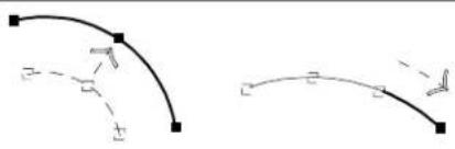 |
| Block Corner Segment midpt. | Segment | Scale about opposite handle Scale width or height about opposite handle | 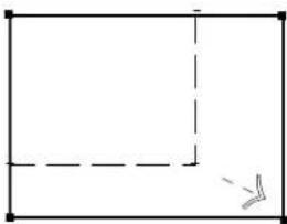 |
| B-spline curve Complex chain Complex shape | Any Scale | about opposite handle | 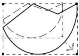 |
| Circle Axis end-point | Modify axis | 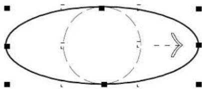 | |
| Ellipse Axis end-point Corner | Modify axis Scale about center | 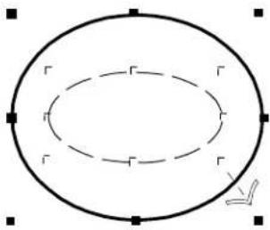 | |
| Line Line string Multi-line Shape5 | Any Move | vertex at handle | 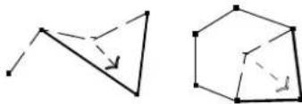 |
| Text Left or right Top or bottom | Scale width about opposite handleScale height about opposite handle | ||
Using the Fence to Manipulate and Modify Elements
In addition to using the Element Selection or PowerSelector tool to group elements for manipulation, you can group elements with the fence. The fence creates a temporary grouping of elements that is ended when the DGN file is closed, if not before. For information about permanent groupings, see "Permanently Grouping Elements" on page 7-2.
Most often, the fence is placed around elements to group them for manipulation, just as the pointer is dragged around elements to select them with the Element Selection tool. However, the fence has two additional grouping capabilities. It can be used:
- As a void to exclude elements inside (or overlapping) the fence boundary.
- To clip elements that cross the fence boundary, like a cookie cutter, so that only the parts inside the fence boundary (or outside in the case of a void) are subject to manipulation.
The fence can be rectangular (referred to as a fence block), polygonal (non-rectangular, referred to as a fence shape, with as many as 5000 vertices), or circular (referred to as a fence circle). A fence shape can be derived from a previously placed shape element.
The Place Fence tool is used to place the fence. On placement, the fence — whether it is a fence block, shape, or circle — is displayed on screen as a closed shape with the color used to highlight identified elements. While the fence is placed, a fence mode icon is displayed in the status bar.
Fences are persistent in both 3D and 2D DGN files. You can place a fence, zoom in on the design and the fence will remain when you zoom back out.
To remove the fence if it is already displayed
- In the Fence tool box, select the Place Fence tool and continue with your work. (In the Main tool frame, Place Fence is the
default "representative" from the Fence tool box.)

You can remove the fence this way to prevent accidental fence manipulations.
Specifying which elements are in the fence contents
The Fence (Selection) Mode determines just what constitutes the fence contents — that is, whether the elements (or parts of elements) inside, outside, or overlapping the fence are “contained” by the fence to be processed.
- Inside — Only those elements completely inside the fence are processed.
• Overlap — Only those elements inside or overlapping the fence are processed. - Clip — Only elements completely inside the fence and parts of elements inside and overlapping the fence are processed. ^3
- Void — Only those elements completely outside the fence are processed.
- Void-Overlap — Only those elements outside or overlapping the fence are processed.
- Void-Clip — Only elements completely outside the fence and parts of elements outside and overlapping the fence are processed. ^3
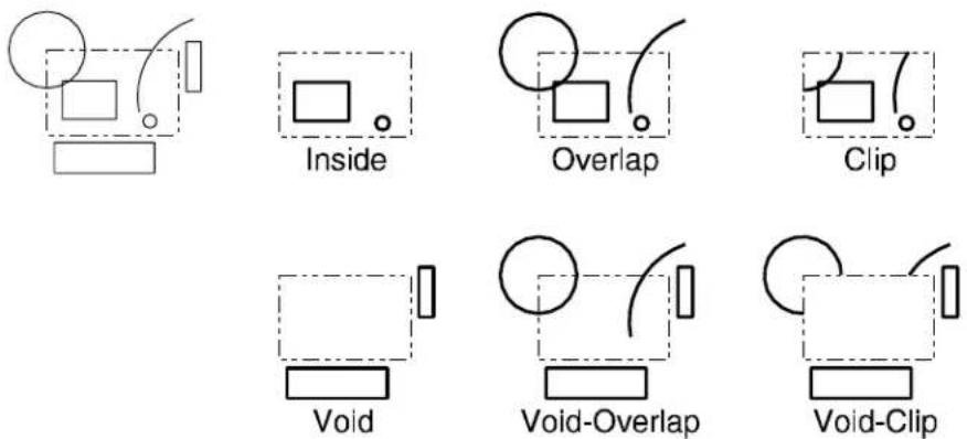
Fence selection modes. Top, the fence and elements. Center Left: Inside; Center Middle: Overlap; Center Right: Clip. Bottom Left: Void; Bottom Middle: Void-Overlap; Bottom Right: Void-Clip.
The Fence Selection Mode is a tool setting (labeled Fence Mode) for the fence tools in the Fence tool box as well as for manipulation tools that can operate on the fence contents. In the latter case, it is set with the option menu next to the Use Fence control. There is also a control in the Locks dialog box.
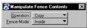
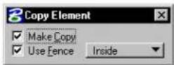
Examples of Tool Settings window controls for setting the Fence Selection Mode.

It is not necessary to place the fence in order to set the Fence Selection Mode. Conversely, once the fence is placed, you can adjust the Fence Selection Mode to change the fence contents without moving or replacing the fence.
To manipulate the fence contents
- Place the fence.

-
Select an element manipulation tool that can be used with the fence contents.
-
In the Tool Settings window, turn on Use Fence and set the Fence Selection Mode.
You are prompted, usually for a data point. For example, with the Delete Fence Contents tool (see page 4-23), you are prompted to “Accept/Reject Fence Contents.”
-
Enter a data point to accept the manipulation or Reset.
-
In some cases, you can repeat the manipulation.

You can Reset to halt a fence manipulation that is in progress. Manipulations that were completed before Resetting remain in the design and can be undone. (Pressing Ctrl-C also halts a fence manipulation.)
Manipulations on many elements
Some fence manipulations on many elements (large arrays, for example) may take a long time to complete.
To minimize potential problems, do the following before attempting such a manipulation:
- Back up the DGN file. For information on how to make a backup copy of the active DGN file, see “Saving and backing up your work” in the QuickStart Guide.
Optimized fence clipping
The Optimized Fence Clipping preference in the Operation category of the Preferences dialog box is on by default. This preference enables you to maintain closed shapes, solids, and surfaces when clipping those elements that cross the fence boundary. If this preference is turned off, closed shapes, solids, and surfaces are dropped to linear elements when clipped.
For more information on the "Operation" category, see the "Preferences dialog box" in online Reference Guide.

MicroStation's ability to place fences with as many as 5000 vertices provides tremendous flexibility when performing clipping operations.
You can also use this preference in conjunction with the Locate By Face preference (in the Input category of the Preferences dialog box) to create associative holes in closed shapes, solids and surfaces. When Locate By Face is set to Always, fences that are located entirely within a closed piece of geometry can perform clip actions upon their section of the larger area.

To create an associative hole inside an element using optimized fence clipping
- From the Workspace menu, choose Preferences.
The Preferences dialog box opens.
- In the Input category, set Locate By Face to Always.
- Click OK to accept the change and close the dialog box.
- Select the Place Fence tool.
- Set the Mode to Clip.
- Inside a closed shape, solid or surface, place a fence.
- Select the Delete Fence Contents
- Accept.

To keep fence clipping from changing the larger geometry in which it is
placed, set Locate By Picking Faces to Never or Render Views Only.
Special fence manipulations

The Manipulate Fence Contents tool (see page 4-20) can be used to "stretch" (extend or shorten) segments of elements that overlap the fence. It does this simply by moving element vertices that fall within the fence. You can also stretch elements that overlap the fence using the Copy tool (see page 4-26), Move tool (see page 4-29), Scale tool (see page 4-33) and Rotate tool (see page 4-40).
The fence contents can also be moved or copied to a new DGN file.
To copy the fence contents to a new DGN file
- In the Key-in window, key in FENCE FILE or FF=.
The Save Fence Contents As dialog box opens. - Key in the name of the new file and set the directory in which it is to be created.
- Click the OK button.
- Accept the copy.
Alternative method — To copy the fence contents to a new DGN file
- In the Key-in window, key in FENCE FILE
or FF= . - Accept the copy.
The file is created in the directory that is pointed to by the MS_DEF configuration variable.

When using the second method, if a file already exists with the specified filename, an alert box warns you that it will be overwritten.
To move the fence contents to a new DGN file
- In the Key-in window, key in FENCE SEPARATE or SF=.
The Save Fence Contents As dialog box opens.
-
Key in the name of the new file and set the directory in which to create it.
-
Click the OK button.
-
Accept the move.
Alternative method — To move the fence contents to a new DGN file
-
In the Key-in window, key in FENCE SEPARATE
or SF= . -
Accept the move.
The file is created in the directory that is pointed to by the MS_DEF configuration variable.

When using the second method, if a file already exists with the specified filename, an alert box warns you that it will be overwritten.
Using the Grid
When working in MicroStation, you have the option of turning on the grid in any view. The grid consists of evenly-spaced points in the design plane. It is a visual measurement and alignment aid at certain magnifications.
Defined spacing between grid points and between grid references (highlighted grid points — every 12th point, for example) are collectively known as grid units. Grid unit settings are specific to each model in a DGN file. The appropriateness of grid unit settings for a design task is related to the size of the design, working units, and the required precision.
When used in conjunction with Grid Lock, the grid can assist
in accurate “by eye” placement of elements (see “Using Grid Lock” on page 3-90). However, the grid can be an impediment to efficiently using AccuDraw (see page 3-26).
Grid Orientation
You can define the orientation of the grid to suit the task at hand. Once you define a grid, Grid Lock works as expected and input points are constrained to the grid points. The Grid Orientation is controlled from the Grid section of the DGN File Settings dialog (select Settings > Design File). Options are:
• View — Grid always aligns to the view and passes through the global origin.
- ACS — Grid aligns to the active ACS.
- Top — Grid aligns to a “Top” view. It extends along the X and Y axes from the global origin.
- Right — (3D only) Grid aligns to a “Right” view. It extends along the Y and Z axes from the global origin.
- Front — (3D only) Grid aligns to a “Front” view. It extends along the X and Z axes from the global origin.
For 2D DGN files, only View, ACS, and Top are applicable. When Grid Orientation is set to anything other than View, then any view rotation will cause the grid to rotate as well.
A further option is a key-in that lets you rotate the grid about (its) Z-Axis. This key-in, ACTIVE GRIDANGLE
To set up grid units
-
From the Settings menu, choose Design File. The DGN File Settings dialog box opens.
-
In the Category list box, select Grid. Controls for adjusting grid unit settings are displayed.
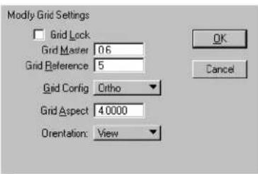
text_image
Modify Grid Settings Grid Lock Grid Master 0.6 Grid Reference 5 Grid Config Ortho Grid Aspect 40000 Orientation: View OK CancelDGN File Settings dialog box (Grid category). Grid Master means the number of grid points per master unit. Grid Reference means the number of grid points between grid references.
-
In the Grid Master field, enter the distance (in Working units) between points in the grid.
-
In the Grid Reference field, enter the number of grid points between grid references.
-
From the Grid Configuration option menu, choose one of these:
| Configura-tion | For grid points laid out as follows |
| Orthogonal Along lines perpendicular to design plane x-axis and y-axis | |
| Isometric | Along lines at 30 from design plane x-axis and y-axis |
| Offset | Rows offset by half the distance between horizontal grid points |
- In the Grid Aspect field, key in the ratio between the grid points along the design x-axis and the distance between
grid points along the y-axis.
In the Isometric configuration, this ratio is fixed.
-
From the Orientation option menu, choose ACS, Top, or View (plus, in 3D, Front and Right).
-
Click the OK button.
To turn on or off the display of the grid in a view
- From the Settings menu, choose View Attributes (or press
).
or
From any view window's control menu, choose View Attributes.
The View Attributes dialog box opens.
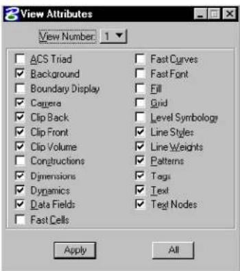
text_image
View Attributes View Number: 1 ACS Triad Background Boundary Display Camera Clip Back Clip Front Clip Volume Constructions Dimensions Dynamics Data Fields Fast Cells Fast Curves Fast Font Fill Grid Level Symbology Line Styles Line Weights Patterns Tags Text Text Nodes Apply All-
From the View Number option menu, choose the number of the desired view.
-
Turn Grid on or off.
-
Click Apply.
To turn on or off the display of the grid in all views
- From the Settings menu, choose View Attributes (or press
).
or
From any view window's control menu, choose View Attributes.
The View Attributes dialog box opens.
-
Turn Grid on or off.
-
Click All.
Using Grid Lock
When Grid Lock is on, all data points and tentative points are forced to fall precisely on a point in the grid.
To set Grid Lock
- From the Settings menu's Locks submenu (or the pop-up Locks menu in the status bar) choose Full.
The Locks dialog box opens.
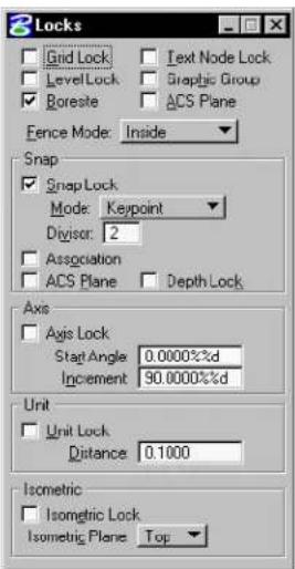
text_image
Locks Grid Lock Text Node Lock LevelLock Graphic Group Boreste ACS Plane Fence Mode: Inside Snap Snap Lock Mode: Keypoint Divisor: 2 Association ACS Plane Depth Lock Axis Axis Lock Start Angle 0.0000%d Increment 90.0000%d Unit Unit Lock Distance 0.1000 Isometric Isometric Lock Isometric Plane Top- Turn Grid Lock on or off.
Alternative method — To set Grid Lock
- In the Settings menu's Locks submenu (or the pop-up Locks menu in the status bar), turn on Grid.
Precision Input Key-ins
Precision input is a method of entering data points with the keyboard. Using this method, you can specify the exact location of a data point by specifying any of the following:
- design plane coordinates, the distances along the x-axis and y-axis (and z-axis in 3D) from the global origin, which has the coordinates “0,0” (“0,0,0” in 3D).
• distance and angle relative to the view x-axis, from the most recently entered tentative point or data point.
• distances, along the design plane axes, from the most recently entered tentative point or data point. - distances, along the view axes, from the most recently entered tentative point or data point.

Using AccuDraw to enter data points is generally superior to using precision input key-ins.
The Data Point Key-in dialog box is used to enter precision input key-ins.

To open the Data Point Key-in dialog box to enter a single precision input key-in
- With the focus in the AccuDraw window, press P .
After you enter the key-in, the dialog box automatically closes.
To open the Data Point Key-in dialog box to enter multiple precision input key-ins
- With the focus in the AccuDraw window, press M .
After you enter a key-in, the dialog box remains open.
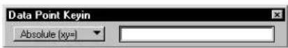
Although you can enter key-ins in the Key-in window, it is easier to use the dialog box. The dialog box has an option menu for choosing the type of key-in (for example, DX=). When you enter the key-in, its type becomes the default.
Locks do not affect data points entered with precision input.
The following table summarizes precision input key-ins:
| Key-in Alternate Key-in | Distance from | Along | |
| POINT ABSOLUTE | XY= | Design plane origin | Design plane axes |
| POINT DELTA | DL= | Last tentative or data point | Design plane axes |
| POINT VDELTA | DX= | Last tentative or data point | View axes |
| POINT DISTANCE | DI= | Last tentative or data point | Relative to view x-axis |
For more information about precision input key-ins, see Precision input key-ins in 3D (see page 8-64).
To enter a data point at specific coordinates in the design plane
- In the Data Point Key-in dialog box, key in POINT
ABSOLUTE x,y or XY=x,y.
X and Y are the x- and y-coordinates, respectively.
Absolute. "GO" denotes the Global Origin; and denote the DGN file x- and y-axes.
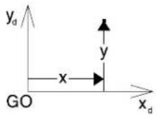
AccuDraw does not provide a means for entering a data point in this manner.
To enter a data point at a distance from the last tentative point or data point and angle relative to the view x-axis
- In the Data Point Key-in dialog box, key in POINT DISTANCE d,Q or DI=d,Q.
d is the distance from the most recently entered tentative point or data point and Q is the angle relative to the view x-axis.
Relative. "P" denotes the last data or tentative point, the view x -axis, and Q the angle.
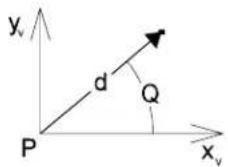
To enter a data point at distances along the design plane axes from the last tentative point or data point
- In the Data Point Key-in dialog box, key in POINT
DELTAx,y or DL=x,y.
X and Y are=the=distances=along=the=design plane x-and=y-axes,=respectively.
Distance. “P” denotes the last data or tentative point; and y_d the DGN file x- and y-axes.
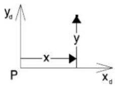
text_image
y_d y x P x_dTo enter a data point at distances along the view axes from the last tentative point or data point
- In=the=Data=Point=Key-in=dialog=box,=keyPOINT VDELTA x,y or DX=x,y.
X and Y are=the=distances=along=the=view x-axis=and y-axis,=respectively.
Distance. “P” denotes the last data or tentative point; x and y the view x- and y-axes.
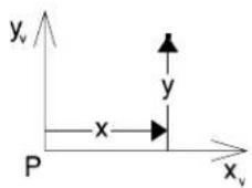
text_image
y_v y x P x_vSyntax notes
The=syntax=of=precision=input=key-ins=includes=provisions for=the=following:
- Specifying the view in which the data point is entered. The view number=optionally=follows=the=last=coordinate,=distance,=or=angle. For=example,=the=key-in=XY=.,1=enters=a=data=point=at the=global=origin=of=the=design=plane=in=View=1. The
equivalent=key-in=in=3D=is=XY=,,1.
•=Entering=multiple data points.=A=number=following=a="|" character=at=the=end=of=a=precision=input=key-in=indicates=how many=data=points=to=enter.=(The=default=is=1.)
For=example,=the=key-in=DL=15|3=enters=three=data=points at=incremental=distances=of=15=master=units=from=the=last tentative=point—or=data=point.
AccuDraw=does=not=provide=a=means=for=entering=multiple data=points=in=this=manner.
• An omitted value in a precision input key-in is assumed to be 0.
For=example,=the=key-iD L=,5:4=is(equal=tD L=0,5:4.
Measure tool box
The=tools=in=the=Measure=tool=box=are=used=to=perform measuring=operations.
| To | Select in the Measutool box |
| Measure=the=distance(s)=alongan=element.orMeasure=the=cumulative=distancefrom=a=data=point.orMeasure=the=perpendicular=distancebetween=an=element=and=a=data=point.orMeasure=the=minimum=distancebetween=two=elements. |  Measure Distance (see page=3-97) Measure Distance (see page=3-97) |
| Measure=the=radius=of=a=circle,=circulararc,=cone,=or=cylinder,=or=the=axes=ofan=ellipse=or=elliptical=arc. |  Measure Radius (see page=3-100) Measure Radius (see page=3-100) |
| Measure the angle between w | es. Measure AngleBetween Lines (see page 3-101) Measure AngleBetween Lines (see page 3-101) |
| Measure the length of an element. |  Measure Length (see page 3-102) Measure Length (see page 3-102) |
| Measure the area and perimeter of a shape, ellipse, or complex shape and to analyze mass properties. |  Measure Area (see page 3-103) Measure Area (see page 3-103) |
| Measure the volume enclosed by an element or a set of elements and to analyze mass properties. |  Measure Volume (see page 3-108) Measure Volume (see page 3-108) |
Key-in: DIALOG TOOLBOX MEASURE [OFF | ON | TOGGLE]

To ensure accurate measurements, snap to the reference elements and points when using measuring tools. For information about snapping, see Snapping to Points on Elements (see page 3-3).
Measure Distance

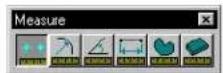
Used to measure distance.
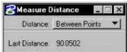
| Tool Setting | Effect |
| Distance | Sets the method of distance measuring.Between Points—Measures the cumulative distance from an origin.Along Element—Measures along an element from an origin.Perpendicular—Measures the perpendicular distance between an element ^1 and a data point.Minimum Between—Measures the minimum distance between two elements. ^1 |
1 Line, line string, multi-line, arc, ellipse, shape, curve, B-spline curve, complex chain, or complex shape.
To measure the cumulative distance from an origin
- Select the Measure Distance tool.
- In the Tool Settings window, set Distance to Between Points.
- Enter a data point to identify the origin (the point from which to measure).
- Enter a second data point.
The distance between that point and the origin is displayed in the status bar. - Enter another data point(s). The cumulative distance from the origin is displayed.
or Reset to return to step 3.
To measure the distance along an element
- Select the Measure Distance tool.
- In the Tool Settings window, set Distance to Along Element.
- Identify the element at the origin (the point from which to measure).
- Enter a data point to define a point along the element. The distance from the origin along the element is displayed in the status bar.
If the element is closed, this data point defines the direction (clockwise or counterclockwise) in which measurements are made. - Enter a data point(s). The distance along the element from the origin is displayed in the status bar.
or Reset to return to step 3.
To measure perpendicular distance from an element
- Select the Measure Distance tool.
- In the Tool Settings window, set Distance to Perpendicular.
- Identify the element.
- Enter a data point.
The perpendicular distance between the element and this point is displayed in the status bar. A temporary “line” is displayed as a visual aid but is not placed in the design. - Enter another data point(s) to define other perpendicular measurements.
- If the element is a line string, shape, curve, complex chain, or complex shape, the distance is measured perpendicular to the segment identified in step 2. or Reset to return to step 3.
To measure the minimum distance between elements
- Select the Measure Distance tool.
- In the Tool Settings window, set Distance to Minimum Between.
- Identify the first element.
- Identify the second element.
- Accept the elements.
The minimum distance between the elements is displayed in the status bar. A temporary “line” is displayed as a visual aid but is not placed in the design.
Key-in: MEASURE DISTANCE [ALONG | MINIMUM | PERPENDICULAR | POINTS]
To construct a minimum distance line between two elements, use the Construct Minimum Distance Line tool (see page 2-32) in the Linear Elements tool box.
Measure Radius

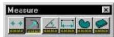
Used to measure:
• The radius of a circle or circular arc.
• The radius of a cone or cylinder.
• The primary and secondary axes of an ellipse or elliptical arc.
- The radius of a circular segment or axes of an elliptical segment of a complex chain or complex shape.
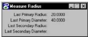
text_image
Measure Radius Last Primary Radius: 20.0000 Last Primary Diameter: 40.0000 Last Secondary Radius: Last Secondary Diameter:To measure an element's radius
- Select the Measure Radius tool.
- Identify the element or segment.
- Accept the element.
The measurement is displayed in the status bar.
Key-in: MEASURE RADIUS
To dimension an element's radius, use the Dimension Element tool.
Measure Angle Between Lines

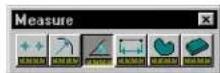
Used to measure the angle between two lines or segments of a line string, shape, or multi-line. If the identified lines do not intersect, an intersection point is computed to serve as the vertex of the measured angle.
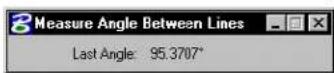
To measure the angle between two lines
- Select the Measure Angle Between Lines tool.
- Identify the first line.
- Identify the second line.
- Accept the lines.
The angle measurement is displayed in the status bar.
Key-in: MEASURE ANGLE
Measure Length

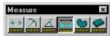
Used to measure the length of an element(s) and to analyze mass properties. For a closed element or a surface, the length of the perimeter or wireframe geometry is measured.

text_image
Measure Length Tolerance (%): 0.001000 Mass Properties Display Centroid Last Length: 53.8383 Last Angle Of Line: 0°| Tool Setting | Effect |
| To le r -ance (%) | When measuring curves, the maximum percentage of the distance between the true curve and the approximation used to measure. A low Tolerance makes the measurement more accurate but increases calculation time. |
| Mass Properties | If on, the Mass Properties window (see page 3-110) displays the mass property analysis. |
| Display Centroid | If on, a graphic crosshair that represents the center of mass for the measured element(s) is displayed. |
To measure the length of an element(s)
- Select the element(s).
- Select the Measure Length tool.
The length is displayed in the status bar. If Mass Properties is on, the mass properties are displayed in the Mass Properties window.
Alternative method — To measure the length of an element(s)
- Select the Measure Length tool.
- Identify the element.
- Accept the element.
The length is displayed in the status bar. If Mass Properties is on, the mass properties analysis is displayed in the Mass Properties window.
Key-in: MEASURE LENGTH
Measure Area

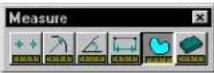
Used to measure area and perimeter.
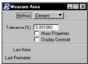
text_image
Measure Area Method: Element Tolerance (%): 0.001000 Mass Properties: Display Centroid Last Area Last Perimeter| Tool Setting Effect | |
| Method | Sets the area that is measured. Element-Area of one closed element^1 (its Area attribute must be Solid). ^2 Fence-Area enclosed by the fence.Intersection-Area bounded by the intersection of two or more closed planar elements.Union-Area bounded by the union of two or more closed planar elements.Difference-Area bounded by the difference between two or more closed planar elements.Flood-Area enclosed by elements that either touch one another or whose endpoints fall within the Maximum Gap. ^3 Points-Planar area with its vertices defined by a series of data points. |
| To l e r a n c e | (%) For curves, sets the maximum percentage of the distance between the true curve and the approximation used to measure. A low Tolerance makes the measurement more accurate but increases calculation time. |
| Mass Properties | If on, the mass property analysis is displayed in the Mass Properties window (see page 3-110). |
| Display Centroid | If on, a graphic crosshair that represents the measured element's center of mass is displayed. |
| Locate Interior Shapes | (When Method is set to Flood) If on, the area enclosed by the bounding elements is calculated, minus the area of any closed elements inside the bounding area. |
| Max(imum)Gap | (When=Method=is=set=to=Flood)=Sets=the largest=distance=allowed=between=consecutive elements. If=zero,=the=elements=must connect=to=bound=an=area. |
1 Planar area of shape, ellipse, complex shape. For 3D surfaces or solids, the total surface area in all dimensions.
2 An element's Area attribute is changed with the Change Element to Active Area tool in the Change Attributes tool box.
3 Somewhat akin to the "flood fill" tool in many paint programs. In 3D, restricted to coplanar elements.
To measure there are and predipetime for eoflementelement
- Use the Element Selection tool (see page 4-2) to select the element.
- Select=the#MeasureAnetootool.
- =Im+hbcTTool=Settings+window=Met+MethooE+to=Element.
4.=Accept=the element.
The elements are a(A)=and perimeter(R=(Bn)min=master units are displayed in the aster bar.
Alternative method — To measure the area and perimeter of one element
- Select=the=Measure Area tool.
2.=In=the=Tool=Settings=window,=set=Method=to=Element.
3.=Identify=the=element.
The=element's=area=(A)=and=perimeter=(P)=in=master=units=are displayed=in=the=status=bar.=If=Mass=Properties=is=on,=the=mass properties=analysis=is=displayed=in=the=Mass=Properties=window.
To measure the area defined by a fence
1.=Use=the=Place Fence (see=page=4-15)=tool=to=place=a=fence.
- Select=the=Measure Area tool.
3.=In=the=Tool=Settings=window,=set=Method=to=Fence.
- Accept=the=fence=contents.
The=fence's=area=(A)=and=perimeter=(P)=in=master=units=are displayed=in=the=status=bar.=If=Mass=Properties=is=on,=the=mass properties=analysis=is=displayed=in=the=Mass=Properties=window.
To measure the area of the intersection or union of closed elements
- Select=the=Measure Area tool.
2.=In=the=Tool=Settings=window,=set=Method=to=Intersection=or=Union.
3.=Identify=one=element.
- Identify=another=element(s).
As=you=accept=each=successive=element,=the=edges=that=do not=serve=as=the=basis=for=the=area=to=measure=are=hidden. The=resulting=area=is=highlighted.
If=the=elements=do=not=overlap,=the=following=occurs, depending=on=the=Method:
| Method If elements do not overlap, then |
| Intersection="Elements=do=not=intersect" is=displayed. |
| Union=Each=element=is=highlighted. |
- After=you=accept=the=last=element,=Reset=to=finish=(or select=a=different=tool).
The=area=(A=)=in=square=master=units=of=the=intersection=or union=is=displayed=in=the=status=bar.=If=the=elements=overlap,=the perimeter=(P=)=is=also=displayed.=If=Mass=Properties=is=on,=the=mass properties=analysis=is=displayed=in=the=Mass=Properties=window.
To measure the area of the difference between elements
- Select=the=Measure Area tool.
2.=In=the=Tool=Settings=window,=set=Method=to=Difference.
If=any=elements=are=selected,=they=are=de-selected.
3.=Identify=the=element—from=which=to=subtract. - Identify=the=element(s)=to=subtract=from=the=element that=was=identified=in=step=3.
5.=After=you=have=identified=all=the=elements=to=subtract=from=the element=identified=in=step=3,=enter=a=data=point=to=accept.
The=edges=that=do=not=serve=as=the=basis=for=the measured=area=are=hidden.
6.=Reset=to=display=the=area=(A)=and=perimeter=(P)=in=master=units in=the=status=bar.=If=Mass=Properties=is=on,=the=mass=properties analysis=is=displayed=in=the=Mass=Properties=window. or
Return=to=step=4=to=identify=more=elements=to=subtract.
To measure the area enclosed by elements that touch or whose endpoints are within the Maximum Gap
- (Optional)=——=Select=the=elements.
- Select=the=Measure Area tool.
3.=In=the=Tool=Settings=window,=set=Method=to=Flood.
4.=(Optional)=If-you=want=to=exclude,=from=the=total=measurement, the=area=of=any=closed=elements=inside=the=selected=area, turn=on=Locate=Interior=Shapes.
5.=Enter=a=data=point=in=the=area=enclosed=by=the=bounding=elements.
6.=Accept=the=elements.
The=area=(A=)=and=perimeter=(P=)=in=master=units=are=displayed in=the=status=bar.=If=Mass=Properties=is=on,=the=mass=properties analysis=is=displayed=in=the=Mass=Properties=window.
To measure an area defined by data points
- Select=the=Measure Area tool.
2.=In=the=Tool=Settings=window.=set=Method=to=Points.
3.=Enter=a=data=point=to=define=each=vertex=of=an=imaginary shape=that=encloses=the=area.
The=imaginary=shape=is=dynamically=displayed.
4.=When=done.=Reset.
The=area=(A=)=and=perimeter=(P=)=in=master=units=are=displayed in=the=status=bar.=If=Mass=Properties=is=on.=the=mass=properties analysis=is=displayed=in=the=Mass=Properties=window.
Key-in: MEASURE AREA [DIFFERENCE | ELEMENT | FENCE | FLOOD | INTERSECTION | POINTS | UNION ]
Measure Volume

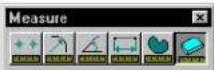
(3D=only)=Used=to=measure=the=volume=enclosed=by=an=element or=a=set=of=elements=and=to=analyze=mass=properties.=The element(s)=must=completely=enclose=a=volume:if=a=volume=is not=enclosed,=a=message=appears=in=the=status=bar.
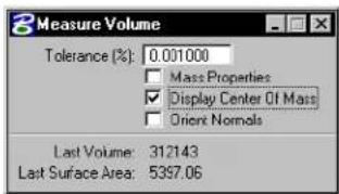
text_image
Measure Volume Tolerance (%): 0.001000 Mass Properties Display Center Of Mass Orient Normals Last Volume: 312143 Last Surface Area: 5397.06| Tool Setting | Effect |
| To le r -ance | For curves, sets the maximum percentage of the distance between the true curve and the approximation used to measure. A low Tolerance makes the measurement more accurate but increases calculation time. |
| Mass Properties | If on, the Mass Properties window (see page 3-110) displays the mass property analysis for the measured volume. |
| Display Centroid | If on, a graphic crosshair that represents the center of mass for the measured element(s) is displayed. |
| Orient Normals | If on, the normal directions of all the selected surfaces are automatically changed to point outward. (The Change Normal Direction tool (see page 8-192) is used to manually change the surface normal direction for a surface.) |
To measure volume
- (Optional) — Select the bounding element(s).
Since only solid cones and solids of projection or revolution can completely enclose a volume by themselves, it is usually necessary to select multiple elements. ^4
- Select the Measure Volume tool.
If an element(s) were selected (step 1), the volume is displayed in the status bar. If Mass Properties is on, the mass properties analysis is displayed in the Mass Properties window. Otherwise, continue with step 3.
-
Identify the element.
-
Accept the element.
The volume is displayed in the status bar. If Mass Properties is on, the mass properties analysis is displayed in the Mass Properties window.
Key-in: MEASURE VOLUME
Mass Properties window
Used to control and display mass properties analysis of the length, area, or volume measured with the Measure Length (see page 3-102) tool, Measure Area (see page 3-103) tool, or Measure Vo l u m e (see page 3-108) tool. This window opens when the Mass Properties tool setting is turned on.
Mass Properties window, displaying only the part that is always visible — the basic properties.
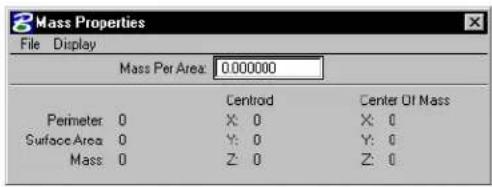
text_image
Mass Properties File Display Mass Per Area: 0.000000 Centroid Center Of Mass Perimeter 0 X: 0 X: 0 Surface Area 0 Y: 0 Y: 0 Mass 0 Z: 0 Z: 0Mass Per
Sets the mass per master unit as follows, depending on which measuring tool is selected:
| Tool selected Sets | |
| Measure Length (see page 3-102) | Mass Per Length — the linear density per master unit. |
| Measure Area (see page 3-103) | Mass Per Area — the area density per square master unit. |
| Measure Vol u m e (see page 3-108) | Mass Per Volume — the volumetric (mass) density per cubic mast |
This setting affects both the Mass and Moments of Inertia.
File menu > Save...
Open the Save Measurement Values dialog box, which is used to save the mass properties analysis in a text file.
Display menu > Moments and Products of Inertia
Toggles the display of the part of the Mass Properties window that shows moments and products of inertia.
| Item name | Shows for measured element(s) |
| Moments of Inertia | Mass moments of inertia — useful for kinematic analysis, including calculating the force required to rotate a body about an axis. |
| Products of Inertia | Mass products of inertia. |
Part of the Mass Properties window that shows Moments and Products of Inertia.
| Coordinate System | Center Of Mass | ||
| Moments Of Inertia | Products Of Inertia | ||
| X: | 0 | XY: | 0 |
| Y: | 0 | XZ: | 0 |
| Z: | 0 | YZ: | 0 |
For closed, planar elements, the area moments of inertia are obtained by setting Mass Per Area to 1.0. In this case, the area moments are displayed as master units to the fourth power. The area moments are required for analyzing the stress across a beam cross section and other areas of engineering analysis.

The combination of the mass moments and polar moments of inertia are commonly referred to as the inertia tensor.

The combination of moments and products of inertia about a given coordinate system can be used to calculate these values for any coordinate system.
Display menu > Principal Moments
Toggles display of the part of the Mass Properties window that shows Principal Moments and Principal Directions.
| Item name | Shows for measured element(s) |
| Principal Moments | The maximum, minimum and an intermediate moment of inertia. |
| Principal Directions | The three mutually perpendicular axes extending from the centroid along which the maximum, minimum and an intermediate moment of inertia occur. The products of inertia about these axes is zero. |
Part of the Mass Properties window that shows Principal Moments and Directions.
| Principal Moments | Principal Directions | ||
| X: 0 | 0.000000 | 0.000000 | 0.000000 |
| Y: 0 | 0.000000 | 0.000000 | 0.000000 |
| Z: 0 | 0.000000 | 0.000000 | 0.000000 |
Display menu > Radii of Gyration
Toggles display of the part of the Mass Properties window that shows the Radii of Gyration, which are an alternate way to express the Moments of Inertia as distances in working units.
Part of the Mass Properties window that shows Radii of Gyration.
| Radi Of Gyration | |
| X | 0 |
| Y | 0 |
| Z | 0 |
Basic properties
This part of the Mass Properties window is always displayed. The exact items displayed on the left side vary depending on the last element measured and the tool used to measure it.
Length
Length, in working units, of a linear element. For surfaces, the length of the wireframe geometry.
Perimeter
Perimeter, in working units, of a closed planar element.
Surface Area
Area of a closed planar element or the surface area of solids in square working units.
Volume
Volume enclosed by a solid, in cubic working units.
Mass
Mass, computed by multiplying the Length, Surface Area, or Volume by the Mass Per
Centroid
Coordinates, in working units, of the center of mass. ^5
4
Element Manipulation and Modification Tools
Once elements are placed, you can move, copy, rotate, scale, delete, and otherwise modify their geometry. In this chapter, you will find information for the tools used in element manipulation and modification. Topics covered include:
• Using the Tools in the Element Selection tool box (see page 4-2)
• Specialized Manipulation and Modification Tools (see page 4-11)
• Using the Tools in the Fence tool box (see page 4-14)
• Using the Tools in the Manipulate tool box (see page 4-25)
• Using the Tools in the Change Attributes tool box (see page 4-56)
• Using the Tools in the Match tool box (see page 4-68)
• Using the Tools in the Drop tool box (see page 4-78)
• Using the Tools in the Modify tool box (see page 4-88)
Using the Tools in the Element Selection tool box
Many element manipulations and modifications can be performed on groups of elements. That is, the elements can be grouped together and the manipulation or modification performed on the group as a whole. Elements may be selected graphically, or you can select elements by their attributes.
Element Selection tool box
The Element Selection tool box contains tools for selecting elements.
| To | Select in the Element Selection tool box |
| Simply select and deselect elements. |  Element Selection (see page 4-2) Element Selection (see page 4-2) |
| Select and deselect elements on a per element basis, by defining an area, or by drawing a line that intersects them. |  PowerSelector (see page 4-5) PowerSelector (see page 4-5) |
Key-in: DIALOG TOOLBOX SELECTION [OFF | ON | TOGGLE]
Element Selection


Used to select an element(s) for modification or manipulation.
While the Element Selection tool is selected, the pointer becomes an arrowhead with an aperture encircling the tip. The aperture denotes the design plane area in which MicroStation searches for elements. The aperture size or Locate Tolerance is a user preference that is adjustable in the Preferences dialog box (Operation category).
For more information on setting the aperture size or Tolerance see "Operation" in the Reference Guide.
If the desired element is visible in the aperture but you cannot select it, check the following:
- To select a shape, the pointer must be close to one of the enclosing lines. To select a circle or an ellipse, the pointer must be close to the circumference or center.
- If Level Lock is on, only elements on the Active Level can be selected.
- If Grid Lock is on, elements can be selected only where they lie on grid points. Some elements may not lie on any grid points.
To select a single element
- Select the Element Selection tool.
- Click the element you want to select.
The selected element is highlighted. ^1
To select one or more elements
- Select the Element Selection tool.
- Drag around the area containing the elements you want to select. As you drag, a dynamic rectangle outlines the area.
- Release the Data button.
All elements that are completely inside the dynamic rectangle are selected.
To select all elements including those not visible
- From the Edit menu, choose Select All.
When the active design file is large, choose Edit > Select All with care. It may take some time to select many elements, and elements are selected regardless of whether they are visible.
To select an additional element
- Select the Element Selection tool.
- Control-click the element to select.
To select one or more additional elements
- Select the El ement Selection tool.
- Hold down the Ctrl key and drag around the area containing the additional elements you want to select.
Be careful not to point at any element that is already selected as you press the Data button.
To also select elements that overlap the dynamic rectangle, hold down the Shift key as well as the Ctrl key as you drag. - Release the Data button.
All elements that are completely inside (or overlapping) the dynamic rectangle when you release the Data button are added to the set of selected elements.
To deselect an element
- Select the Element Selection tool.
- Control-click the element to deselect.
To deselect all elements
- Select the Element Selection tool.
- Click somewhere in the view where there is no element.
Key-in: CHOOSE ELEMENT

It is possible to select elements based on their attributes. See "Selecting Elements Based on Attributes" on page 7-133.

Control-click means to hold down the Ctrl key while clicking the Data button.

If you select an element, all other elements are deselected.

Selecting Element Selection automatically disables AccuDraw if it was not already disabled. To activate AccuDraw for use with Element Selection, select the Toggle AccuDraw tool in the Primary Tools tool box.
PowerSelector


The PowerSelector tool is used to select and deselect multiple elements in a variety of ways.
Attribute tabs in the PowerSelector settings window let you select elements by one or more attributes — Level, Color, Style, Weight, Type, or Class. Alternatively, when you select elements graphically, the active set of attributes displays as a highlighted group at the top of each tab list box.
You can add to the set in each tab by clicking additional (unhighlighted) attributes. If an element exists with that attribute, the attribute will be included in the set. Similarly, you can remove an attribute from the set by clicking a highlighted attribute. Switching tabs lets you continue the process of adding or eliminating other attributes for the selection set. Where you have a number of attributes selected you can
For complex elements, such as cells, which can contain multiple attributes in a single instance, PowerSelector applies a simple selection logic. The attributes Level, Color, Style, Weight, and Class will locate
simple elements within a complex element and then act upon the entire complex element. Because the Types attribute supports exact matches only, it is not generally useful for complex elements that normally consist of different element types. For example, a cell comprised of two red lines and two blue circles would be selected by a scan for red elements but not by a scan for circles.
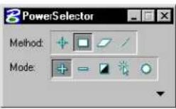
| Tool Setting | Effect |
| Method | Sets the selection method:Individual—lets you select elements graphically on a per element basis, as with the regular Element Selection tool (see page 4-2). If you enter a data point but miss an element, the Block Method activates.Block Inside—all elements inside the defined block are selected.Block Overlap—all elements inside plus those overlapping the defined block are selected.Shape Inside—all elements inside the defined shape are selected.Shape Overlap—all elements inside plus those overlapping the defined shape are selected.Line—lets you select elements by defining a line that intersects them. |
Element Manipulation and Modification Tools
PowerSelector
| Tool Setting | Effect |
| Mode | Sets the objective of using the tool:Add—selects elements.Subtract—deselects elements.Invert—toggles the selection status of an element (selects deselected elements and deselects selected elements).New—clears the current selection set and starts a new set.Clear / Select All—deselects all selected elements, or selects all elements if no elements are currently selected. |
| Attribute Tabs | Clicking the Show Selection Information arrow expands the Tool Settings window to reveal the Attribute tabs.Lv (Level)—lets you select the required levels from a list (1–63 plus any named levels present).Co (Color)—lets you select the required colors from a list (0–254 plus By Level).Lc (Style)—lets you select the required line styles from a list (0–7 plus any custom line styles present).Wt (Weight)—lets you select the required line weights from a list (0–31 plus By Level).Ty (Type)—lets you select the required element types from a list.Cl (Class)—lets you select the required element classes from a list. |
To select elements inside or overlapping a rectangular area
- Select the PowerSelector tool.
- In the Tool Settings window, select the following icons: Method - Block, and Mode - Add (+)
If Block is set to Inside — the block has a solid border and no dashed line running through it.
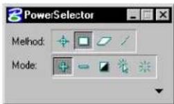
If Block is set to Overlap — the block has a dashed border and a dashed line running through it.
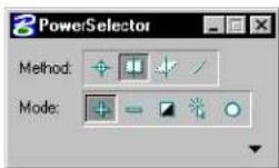
- (Optional) — To change between Inside and Overlap, select the icon again using either the keyboard shortcut or the pointer.
- Enter a data point to define the first corner of the block.
- Move the pointer until the dynamically displayed block contains or overlaps the elements you want to select.
- Enter a second data point to close the block.
To select elements contained in or overlapping a polygonal area
- Select the PowerSelector tool.
- In the Tool Settings window, select the following icons:
Method - Shape, and Mode - Add (+)
- (Optional) — To change between Inside and Overlap, select the icon again using either the keyboard shortcut or the pointer.
- Enter a data point to define the first vertex of the polygonal shape.
- Continue entering data points until the polygonal shape contains or overlaps the elements you want to select.
- Enter a final data point to close the polygonal shape.
To select elements that intersect a line
- Select the PowerSelector tool.
- In the Tool Settings window, select the following icons: Method - Line, and Mode - Add (+)
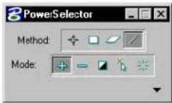
- Enter a data point to begin the line.
- Enter a data point to end the line.
All elements touched by the line are selected.
To select elements based on their attributes
- Select the PowerSelector tool.
- In the Tool Settings window, select the following icon: Mode - Add (+)
- In the Tool Settings window, click the Show Selection Information icon.
- Choose the desired Attribute tab as the selection criterion.
- In the Attribute list box, click the attributes to be included in the selection criterion.
If elements exist with these attributes in the design file,
the attributes are highlighted and displayed at the top of the list box and the elements are selected. If you select an attribute that does not coincide with an element in the design file, the attribute is not highlighted.
To select additional elements or deselect some selected elements based on their attributes
- Select the PowerSelector tool.
- In the Tool Settings window, select the following icons: Method - Block, and Mode - Add (+) or Subtract (-)
- (Optional) — To change between Inside and Overlap, select the icon again using either the keyboard shortcut or the pointer.
- Enter a data point to define the first corner of the block.
- Move the pointer until the dynamically displayed block contains or overlaps the elements you want to select or deselect.
- Enter a second data point to close the block.
Elements that meet the criterion within the block are selected. - In the Tool Settings window, click the Show More Information icon.
- Choose the desired Attribute tab.
The attributes that exist within the selection set (block) are highlighted and display at the top of the list box. - To deselect elements with specific attributes from the selection set, click the highlighted attribute.
The attribute is no longer highlighted and the elements with that attribute are unselected
Key-in: POWERSELECTOR
For users who prefer it, both Method and Mode have been mapped to the keyboard. Note that left and right-handed configurations are available simultaneously.
| Tool setting Keyboard shortcut | |
| Method | Individual — Q or U Block — W or I Shape — E or O Line — R or P |
| Mode | Add — A or J Subtract — S or K Invert — D or L New — F or · Clear/Select All — G or · (Note thatpressing spacebar also deselects all elements.) |
For instance, the Method keys Q or U select the Individual Method, W or I the Block Method, E or O the Shape Method, and R or P the Line Method; case is iunimportant.

Selections through PowerSelector can be undone in order of selection through the use of Ctrl-Z or Edit >Undo.

You can set a user preference Disable Edit Handles to display selected elements as highlighted instead of with handles.

To change between Inside and Overlap mode, select the Block or Shape icon with the pointer or use the relevant keyboard shortcut.
Specialized Manipulation and Modification Tools
When you need to manipulate or modify elements with more precision than is possible with the Element Selection or PowerSelector tools, or if you need to delete elements, use a specialized element manipulation or modification tool. These tools can be used in conjunction with either the Element Selection or the PowerSelector tool or by themselves.
This table summarizes the tool boxes that contain specialized tools used to place, manipulate, and modify elements.
| To | Use a tool in the |
| Copy, move, scale, rotate, or mirror elements. | Manipulate tool box (see page 4-25) |
| Change (attributes, level, etc. of) elements. | Change Attributes tool box (see page 4-56) |
| Modify (the shape or size of) elements. | Modify tool box (see page 4-88) |
To use specialized tools
- In the Element Selection tool box, select the Element Selection tool.

- Select the element(s) (see page 4-1).
- Select the specialized tool.
- Perform the desired manipulation or modification.
Alternative method — To use specialized tools
- Select the specialized tool.
The prompt "Identify element" is displayed in the status bar. The pointer has a circular aperture that works like the aperture on the Element Selection arrowhead pointer.

- Enter a data point on or near a desired element to identify the element. In some cases it may be helpful to first snap a tentative point to the element. See "Snapping to tentative points on elements" on page 3-4.
The element is highlighted, and the prompt "Accept/reject
element" is displayed in the status bar.
- To accept the element and continue, enter a data point anywhere in any view except on an element. or
To identify a different element, Reset and return to step 2.
- Enter additional data points to perform (and in some cases, repeat) the desired manipulation.
- (Optional) — Repeat steps 2–4 for each additional element. (The tool must have been locked upon selection in step 1.)

The first method is referred to as noun-verb because the element(s) are distinguished before the specialized tool is selected. The second method is referred to as verb-noun. All specialized tools work with the verb-noun method. Not all can be operated noun-verb. When you select a tool that does not work on a noun-verb basis, MicroStation automatically de-selects any selected elements.
Fence tool box
The Fence tool box contains tools that are used to place, modify, move the fence, and delete the fence contents.
| To | Select in the Fence tool box |
| Place the fence. |  Place Fence (see page 4-15) Place Fence (see page 4-15) |
| Modify one vertex of a fence. |  Modify Fence (see page 4-19) Modify Fence (see page 4-19) |
| Manipulate the fence contents.or Extend or shorten elements that overlap the fence. |  Manipulate Fence Contents (see page 4-20) Manipulate Fence Contents (see page 4-20) |
| Delete the fence contents. |  Delete Fence Contents (see page 4-23) Delete Fence Contents (see page 4-23) |
| Break up the complex elements in the fence contents into their components. |  Drop Complex Status of Fence Contents (see page 4-24) Drop Complex Status of Fence Contents (see page 4-24) |
Key-in: DIALOG TOOLBOX FENCE [OFF | ON | TOGGLE]

To prevent accidental fence manipulations, remove a no longer needed fence by selecting the Place Fence tool.
Place Fence

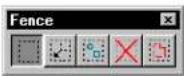
Used to place the fence.
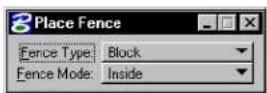
| Tool Setting | Effect |
| Fence Type | When the Fence Type is:Block, Shape, or Circle—Sets the geometric characteristics of the fence for graphical placement.(from) Element, From View, or From Design File—Sets the entity from which the fence is derived. |
| Fence Mode | Sets the Fence (Selection) Mode that, in conjunction with the fence placement, defines the fence contents for manipulation. See “Specifying which elements are in the fence contents” on page 3-81. |
| Design (For 2D files only) With Fence Type set to From Design File, sets the design file(s) from which the fence is derived — Active or All (active design file and attached references). The Choose option is used to identify a file — either the active design file or an attached reference — by identifying one of its elements. | |
To place a rectangular fence
- Select the Place Fence tool.
If a fence already exists, it is removed.
- In the Tool Settings window, set Fence Type to Block.
- Enter a data point to define one corner.
- Enter a data point to define the diagonally opposite corner.
Place Fence, with Fence Type set to Block.
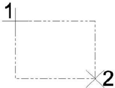
text_image
1 2Alternative method — To place a rectangular fence
- Select the Place Fence tool.
If a fence already exists, it is removed.
- In the Tool Settings window, set Fence Type to Block.
- Drag the pointer from the first corner to the diagonally opposed corner.
To place a polygonal (non-rectangular) fence
- Select the Place Fence tool.
If a fence already exists, it is removed.
- In the Tool Settings window, set Fence Type to Shape.
- Enter a data point to define the beginning (and end) point.
-
Continue to enter data points to define the vertices.
-
To close the shape, enter a data point at the location of the first data point.
or Click the Close Fence button. or Key in CLOSE ELEMENT.
Place Fence, with Fence Type set to Shape.
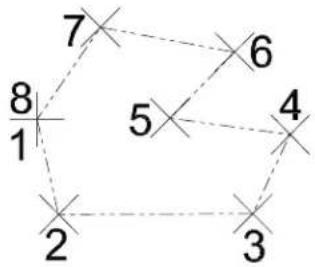
text_image
7 6 8 5 4 2 3Alternative method — To place a polygonal (non-rectangular) fence
- Select the Place Fence tool.
If a fence already exists, it is removed. - In the Tool Settings window, set Fence Type to From Shape.
- Identify a shape element that is the same shape as the fence shape you want to place.
- Enter a data point to accept the element.
The fence is placed directly on top of the element.
To place a circular fence
- Select the Place Fence tool.
If a fence already exists, it is removed. - In the Tool Settings window, set Fence Type to Circle.
- Enter a data point to define the center.
- Enter a data point to define the radius.
Alternative method — To place a circular fence
- Select the Place Fence tool.
If a fence already exists, it is removed. - In the Tool Settings window, set Fence Type to Circle.
- Drag the pointer from the center to the perimeter.
Toplaceafenceonanexistingshapeelement
- Select the Place Fence tool.
If a fence already exists, it is removed. - In the Tool Settings window, set Fence Type to Element.
- Identify a shape element that is the same shape as the fence shape you want to place.
- Enter a data point to accept the element.
The fence is placed directly on top of the element.
Key-in: PLACE FENCE [BLOCK | SHAPE | CIRCLE | FROMSHAPE | ELEMENT | VIEW | DESIGN | UNIVERSE | ACTIVE | ALLFILES]

If the Fence (Selection) Mode is set to Clip, the From Shape option duplicates the selected shape to be placed. This option works only with simple shapes; it does not work with complex shapes at this time.

Selecting Place Fence automatically disables AccuDraw if it was not already disabled. To activate AccuDraw for use with Place Fence, select the Toggle AccuDraw tool in the Primary Tools tool box.

If, after placing the fence but before selecting another tool, you decide the fence placement is unsatisfactory, simply Reset to begin re-placing it.
Modify Fence

Used to move the fence or modify one of its vertices.
The fence and the Fence (Selection) Mode define the fence contents for manipulation. See “Specifying which elements are in the fence contents” on page 3-81.
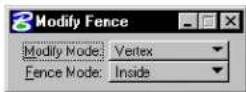

To move the fence without replacing it
- Select the Modify Fence tool.
- Set the tool setting Modify Mode to Position.
- Enter a data point to define the origin for the move.
- Enter a data point to define the new fence position. This data point precisely positions the origin.
- Reset to accept the move. or Repeat step 4.
▶ Tomodifyavertexofthefence
- Select the Modify Fence tool.
- Set the tool setting Modify Mode to Vertex.
- Identify the vertex to move.
- Enter a data point to define the new vertex position.
- Reset to accept the modification.
or Repeat step 4.
Modify Fence etex
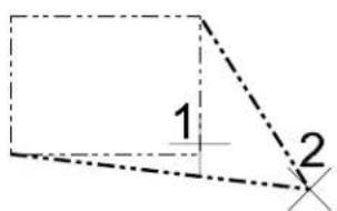
text_image
1 2Key-in:

Selecting Modify Fence automatically disables AccuDraw if it was not already disabled. To activate AccuDraw for use with Modify Fence, select the Tgggle AccuDraw tool in the Primary Tools tool box.
Manipulate Fence Contents

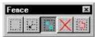
Used to move, copy, rotate, mirror, scale, or stretch the fence contents, which are defined by the fence and (except for stretching)
4-20 MicroStation User Guide
the Fence (Selection) Mode. See “Specifying which elements are in the fence contents” on page 3-81.
The method of manipulation is determined by the tool setting Operation. With the exception of Stretch, each Method works identically to a tool in the Manipulate tool box with the tool setting Use Fenceon.
| Operation Identical to using this tool with Use Fen on | |
| Copy Copy (see page 4-26) | |
| Move Move (see page 4-29) | |
| Scale Scale (see page 4·33) | |
| Rotate Rotate (see page 4-40) | |
| Mirror Mirror (see page 4-47) |
With Operation set to Stretch, Manipulate Fence Contents ignores the Fence (Selection) Mode and operates on elements as follows:
- A vertex of a line, line string, multi-line, or shape is moved if it is inside the fence. A vertex outside the fence is not moved.
• An endpoint of an arc is moved if it is inside the fence. An arc endpoint outside the fence is not moved.
• An ellipse, circle, or cell is moved if it is completely inside the fence.
Fence Stretch has always been a powerful tool when working on B-spline surfaces, because it allows you to move many poles (also known as control points) at once. With Fence Stretch built into the Rotate and Scale tools, this dramatically increases the power to bend and distort surfaces while keeping them smooth.
For general information about B-spline surfaces, see “3D Elements” on page 8-51.
You can use Fence Stretch to manipulate breaks (breaks in multi-lines are often used to represent windows or doorways when the multi-line itself is the wall). For instance, you can place your fence to include a window, and move the window along the wall. You may also change the size of the window by including only the start or end of the break in the fence. This means that in most cases, you do not have to drop the multi-line into its component elements to perform such manipulations.
For general information about multi-lines, see "Using Multi-lines" on page 7-26.
You cannot move the break off the multi-line segment that contains it. If you move the fence so the start or endpoint of a break would move off the segment, the break position will simply be projected to the nearest point on the segment. If you move a break off the end of the segment, it will simply be deleted.
If only one endpoint of the arc is in the fence, the arc is effectively rotated and scaled so that the point is moved to the new position. This means that arcs do not change their aspect ratio (for example, circular arcs do not become elliptical) or their sweep angle. Their new endpoint position remains consistent with how the fence was moved, instead of Fence Stretch simply scaling arcs in either x or y.
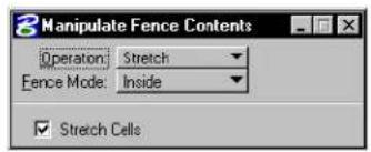
text_image
Manipulate Fence Contents Operation: Stretch Fence Mode: Inside ✓ Stretch Cells| Tool Setting | Effect |
| Stretch Cells | If on, cells that overlap the fence are stretched. ^1 |
1 The LOCK CELLSTRETCH [OFF | ON | TOGGLE] key-in also can be used to turn Stretch Cells off or on.
To stretch segment of element that overlap the reference
- Select the Manipulate Fence Contents tool.
- Set Operation to Stretch.
The Stretch option ignores the Fence (Selection) Mode. The mode has no effect while the Stretch option is in use. - Enter a data point inside the fence to define the origin.
- Enter a data point to reposition the fence and the affected vertices.
Manipulate Fence Contents tool with Operation setto Stretch.
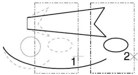
text_image
1 2×Key-in: FENCE ICON

The relative positions of cuts, breaks and partial deletions in multi-lines are maintained during stretch and move operations.

To constrain the movement of vertices to multiples of an angle, use AccuDraw (see page 3-26) in conjunction with the Stretch option for Manipulate Fence Contents.
Delete Fence Contents

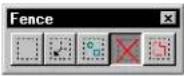
Used to delete the fence contents, which are defined by the fence and the Fence (Selection) Mode. See "Specifying which elements are in the fence contents" on page 3-81.
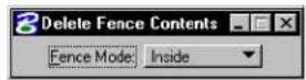
To delete the fence contents
-
Select the Delete Fence Contents tool.
-
Accept the deletion.
Key-in: FENCE DELETE
Drop Complex Status of Fence Contents

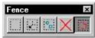
Used to break up the complex elements (cells, complex chains, complex shapes, text nodes, surfaces, and solids) in the fence contents into their components. The elements can then be manipulated individually.
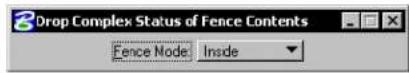
| Tool Setting | Effect |
| Fence (Selection) Mode | Sets how the fence contents are determined. See “Specifying which elements are in the fence contents” on page 3-81. |
To drop the complex status of the fence contents
-
Select the Drop Complex Status of Fence Contents tool.
-
Accept the drop.
Key-in: FENCE DROP COMPLEX
To selectively break up a specific complex element(s), use the Drop Complex Status (see page 4-80) tool.
The Drop Complex Status of Fence Contents tool cannot be used to disassociate a B-spline curve from its control polygon.
Manipulate tool box
The tools in the Manipulate tool box are used to copy, move, resize, rotate, mirror, and create arrays of elements.
| To | Select in the Manipulate tool box |
| Copy or stretch an element (s |  Copy Element (see page 4-26) Copy Element (see page 4-26) |
| Move or stretch an element (s |  Move Element(see page 4-29) Move Element(see page 4-29) |
| Move or copy an element with the sides of the copy parallel to the original. |  Move Parallel (see page 4-31) Move Parallel (see page 4-31) |
| Resize and stretch an element(s) by the active scale factors. |  Scale (see page 4-33) Scale (see page 4-33) |
| Rotate and stretch an element(s). |  Rotate (see page 4-40) Rotate (see page 4-40) |
| Mirror an element(s). |  Mirror (see page 4-17) Mirror (see page 4-17) |
| Align an element(s) to ane another element. |  Align Edges (see page 4-50) Align Edges (see page 4-50) |
| Copy an element(s) many times to create a rectangular or a polar (circular) array. |  Construct Array (see page 4-52) Construct Array (see page 4-52) |
Key-in: DIALOG TOOLBOX MANIPULATE[OFF | ON | TOGGLE]

To manipulate elements in an attached reference, use reference tools (see "Working with attached reference design files" on page 6-14).
Copy Element

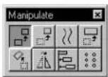
Used to copy or stretch an element(s).
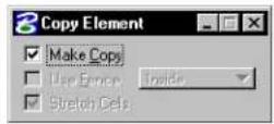
| Tool Setting | Effect |
| Make Copy | If off, the window switches to the Move Element settings window. |
| Use Fence | If on, the fence contents are copied. The option menu sets the Fence (Selection) Mode. |
| Stretch Cells | If on, the fence contents are stretched, when Fence (Selection) Mode is Stretch. |
To copy an element(s)
- Select the Copy tool.
- Identify the element.
- Enter a data point to position the copy.
Alternative method — To copy an element(s)
- Select or fence the element(s).
- Select the Copy tool.
- Enter a data point to define the origin for the copy.
- Enter a data point to position the copy.
Copy tool. Left, identifying an element to copy. Right, copying the fence contents with Use Fence on.
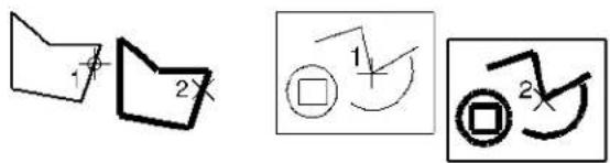
text_image
Hand-drawn diagrams showing geometric shapes with annotations and symbols, including a folder, rectangle, and curved arrows.To stretch elements in a fence
- Using the Place Fence tool (see page 4-15), place a fence around an element or group of elements.
- From the Manipulate tool box, select the Copy tool. The Copy Element settings window opens.
- From the Use Fence option menu, choose Stretch. The Use Fence check box activates, and the Stretch Cells check box also activates.
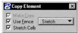
- Enter a data point inside the fence to define the origin.
- Enter a data point to reposition the fence and the affected vertices.
Stretching elements in a fence using the Copy Element tool. Enter a data point to define the origin of the fence (1), then a second data point to reposition the affected vertices (2).
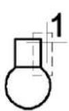
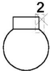
text_image
2
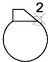
Key-in: COPY ICON
Key-in: FENCE COPY ELEMENT

To constrain the movement of copies to multiples of an angle, use AccuDraw in conjunction with the Copy tool (see "AccuDraw" on page 3-26).

To copy the fence contents to a new design file, see the procedure
in "Special fence manipulations" on page 3-85.

You cannot stretch all vertices outside of the fence. Because Stretch is treated as a Fence Mode, you cannot combine Void and Stretch.

The Fence Stretch option works the same from both the Copy Element and Move Element settings window.
Move Element


Used to move or stretch an element(s).
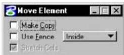
| Tool Setting | Effect |
| Make Copy | If on, the window switches to the Copy Element settings window. |
| Use Fence | If on, the fence contents are moved. The option menu sets the Fence (Selection) Mode. |
| Stretch Cells | If on, the fence contents are stretched, when Fence (Selection) Mode is Stretch. |
To move an element
- Select the Move tool (be sure Use Fence is off).
- Identify the element.
- Enter a data point to reposition the element.
To move one or more selected elements
- Select the element(s).
- Select the Move tool.
Be sure Use Fence is off. - Drag a selected element by any point on the element except the handles.
All selected elements move.
To move the fence contents
- Place a fence around the element(s).
- Select the Move tool.
Be sure Use Fence is on. - Enter a data point to define the origin for the move.
- Enter a data point to reposition the fence contents.
Move tool. Left, identifying an element to move. Right, moving the fence contents with Use Fence on.

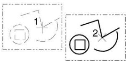
text_image
1 2Key-in: MOVE ICON
4-30 MicroStation User Guide
Key-in: FENCE MOVE ELEMENT

To constrain movement to multiples of an angle, use AccuDraw in conjunction with the Move tool (see "AccuDraw" on page 3-26).

To move the fence contents to a new design file, see the procedure in "Special fence manipulations" on page 3-85.
Move Parallel

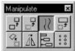
Used to move or copy an element (line, line string, multi-line, curve, arc, ellipse, shape, complex chain, or complex shape) parallel to the original.
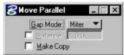
| Tool Setting | Effect |
| Gap Fill Mode | Determines the method by which the gap created by moving two connected elements to a parallel location is filled.Miter—Fills the gap by calculating a new intersection point that is the same angle relative to the original intersection point.Round—Fills the gap with a rounded arc between the two moved elements. |
| Distance | If on, sets the distance to move. |
| Make Copy | If on, the element is copied and the original is not manipulated. |
To move or copy an element parallel to the original
- Select the Move Parallel tool.
- Identify the element.
- Enter a data point.
| Distance Defines |
| Off Distance and direction. |
| On Direction only. |
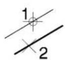
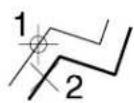
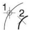
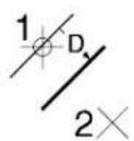
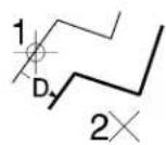
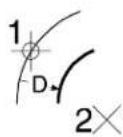
Move Parallel tool. Above: Defining distance with a data point (Distance off) and Gap Mode set to Mitred. Below: Distance is keyed in (Distance on). In illustrations, Make Copy is on.
Comparison of using the Move Parallel tool with Gap Mode set to Mitred (left) and Rounded (right).
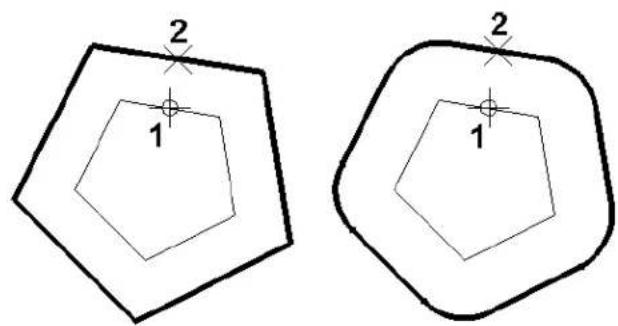
text_image
2 1 2 1Key-in: MOVE PARALLEL ICON
Key-in: [COPY | MOVE] PARALLEL [DISTANCE | KEYIN]

You can instead use the Move Element tool (see page 4-29) in conjunction with AccuDraw to constrain element movement.
Scale

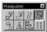
Used to resize and stretch an element(s). Elements can be scaled individually, as a selected group, or within the fence. When About Element Center is turned on, selected elements are scaled about their (individual) center points.
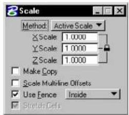
text_image
3 Scale Method Active Scale X Scale 1.0000 Y Scale 1.0000 Z Scale 1.0000 Make Copy Scale Multiline Offsets Use Fence Inside Stretch Cells| Tool Setting | Effect |
| Method Sets the method. Active Scale—Scale by the active scale factors (X Scale, Y Scale, and Z Scale). If a scale factor is 0-1 (for example, 0.25), size in that direction is decreased; if a scale factor is greater than 1, size in that direction is increased.3 points—Scale graphically, through the entry of three data points. The scale factors are computed by dividing the distance between the first and third points by the distance between the first and second points. | |
| X Scale | Scale factor along view x-axis (horizontal), when Method is Active Scale. |
| Y Scale | Scale factor along view y-axis (vertical), when Method is Active Scale. |
| Z Scale | (3 D only) Scale factor along view z-axis (depth), when Method is Active Scale. |
| Proportional | If on, the element(s) proportions are maintained, when Method is 3 points. |
| Make Copy | If on, the element(s) are copied and the copy(s) are scaled; the original(s) are not manipulated. |
| Scale Multi-line Offsets | If on, multi-line offsets are scaled (for example, to scale wall thickness when resizing a room). |
| Use Fence | If on, the fence contents are scaled. The option menu sets the Fence (Selection) Mode. |
| Stretch Cells | If on, the fence contents are scaled and stretched, when Fence (Selection) Mode is Stretch. |
| About Element Center | If on, in Extended Information section of tool settings, the selected element(s) is scaled about its center point instead of a selected point. Elements may be selected individually, or you can select multiple elements to scale in a selection set or using the fence. Where multiple elements are selected, they all will be scaled about their own center points. |
To scale an element(s) by the active scale factors
- Select or fence the element(s).
- Select the Scale tool.
- In the Tool Settings window, set Method to Active Scale.
- Enter a data point to define the point about which the element(s) are scaled.
Alternative method — To scale an element(s) by the active scale factors
- Select the Scale tool.
- In the Tool Settings window, set Method to Active Scale.
- Identify the element.
- Enter a data point to define the point about which the element(s) are scaled.
Scale, = with = Method set = to = Active = Scale. Illustrations show X Scale === 2.0, = Y = Scale === 0.5, = and = Make = Copy on.
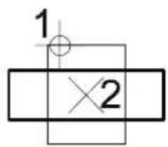
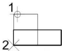
text_image
1 2To scale an element(s) graphically
- Select or fence the element(s).
- Select the Scale=tool.
- In the Tool Settings window, set Method to 3 points.
- Enter a data point to define the point to scale about.
- Enter a data point to define a known location or keypoint.
- Enter a data point to define scaling factors.
Alternative method — To scale an element(s) graphically
- Select the Scale=tool.
- In the Tool Settings window, set Method to 3 points.
- Identify the element.
- Enter a data point to define the point to scale about.
- Enter a data point to define a known location or keypoint.
- Enter a data point to define scaling factors.
Scale, with Method set to 3 points.
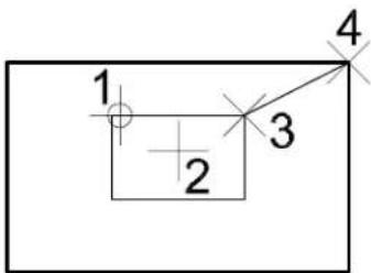
text_image
1 2 3 4To scale and stretch elements in a fence
- Using the Place Fence tool (see page 4-15), place a fence around an element or group of elements.
- Select the Scale tool.
The Scale settings window opens.
- From the Use Fence option menu, choose Stretch.
The Use Fence check box activates and the Stretch Cells check box also activates.
- On the Method option menu, choose Active Scale and type values in the X, Y (Z) fields.
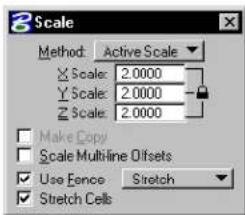
text_image
Scale Method: Active Scale X Scale: 2.0000 Y Scale: 2.0000 Z Scale: 2.0000 Make Copy Scale Multiline Offsets Use Fence Stretch Stretch Cells- Enter a data point to define the point about which
the element(s) are scaled.
The element(s) are stretched by the Active Scale.
Scaling and stretching elements in a fence using the Scale tool. Enter a data point (1) to define the point about which the element(s) are scaled.
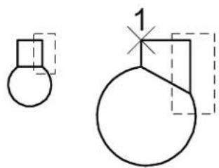
natural_image
Pure geometric diagram showing two shapes with dashed outlines and a labeled point '1' (no text or symbols beyond basic geometry)To graphically scale and stretch elements in a fence
- Using the Place Fence tool (see page 4-15), place a fence around an element or group of elements.
- Select the Scale tool.
The Scale settings window opens.
- From the Use Fence option menu, choose Stretch.
The Use Fence check box activates and the Stretch Cells check box also activates.
- On the Method option menu, choose 3 points.
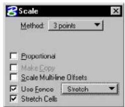
text_image
3 Scale Method: 3 points Proportional Make Copy Scale Multiline Offsets Use Fence Stretch Stretch Cells- Enter a data point to define the point about which
the element(s) are scaled.
-
Enter a data point to define a known location or keypoint.
-
Enter a data point to define scaling factors.
The element(s) are graphically scaled and stretched.
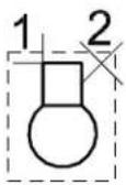
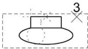
text_image
3Enter a data point (1) to define the point about which the element(s) are scaled. Enter a data point (2) to define a reference point for the scaling. Enter a data point (3) to define the amount of scaling.
To scale elements, in a fence, about their centers (by a scale factor)
-
Use the Place Fence tool (see page 4-15) to place a fence around the elements.
-
Select the Scale tool.
The Scale settings window opens.
-
Set Method to Active Scale and set the scale factor.
-
Turn on About Element Center (in the Extended Information section of the tool settings).
-
Enter a data point to accept the scaled elements.
Left: Selecting the elements to scale with a fence. Right: After scaling the elements with About Element Center turned on (originals shown dashed).
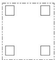
natural_image
Simple geometric diagram with four empty squares inside a dashed rectangular border (no text or symbols)
natural_image
Four identical square diagrams with dashed internal lines, arranged in a 2x2 grid (no text or symbols)Key-in: SCALE ICON
Key-in: FENCE SCALE POINTS [COPY | ORIGINAL]
Rotate

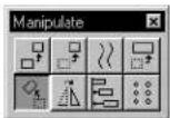
Used to rotate and stretch an element(s). Elements can be rotated individually, as a selected group, or within the fence. When About Element Center is turned on, selected elements are rotated about their (individual) center points.
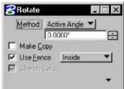
text_image
3 Rotate Method Active Angle 0.0000° Make Copy Use Fence Inside Stretch Cells| Tool Setting | Effect |
| Method | Sets the method used to rotate and stretch an element. Active Angle—the element(s) are rotated by the Active Angle, which can be keyed in.2 P o i n t s —the angle of rotation is defined by entering two data points.3 p o i n t s —the angle of rotation is defined by three data points. |
| Make Copy | If on, the element(s) are copied and the copy(s) are rotated; the original(s) are not manipulated. |
| Use Fence | If on, the fence contents are rotated. The option menu sets the Fence (Selection) Mode. |
| Stretch Cells | If on, the fence contents are rotated and stretched, when Fence (Selection) Mode is Stretch. |
| About Element Center | If on, in Extended Information section of tool settings, the selected element(s) is rotated about its center point instead of a selected point. Elements may be selected individually, or you can select multiple elements to rotate in a selection set or using the fence. Where multiple elements are selected they all will be rotated about their own center points. |
To rotate an element(s)
- Select or fence the element(s).
- Select the Rotate tool.
- Enter a data point to define the pivot point.
If Method is set to Active Angle, the elements(s) are rotated by the Active Angle; repeat to rotate the element(s) again. Otherwise, continue with step 4.
- If Method is set to 2 Points, enter a data point to define the angle of rotation graphically.
or If Method is set to 3 points, enter a data point to
define the start of rotation.
If Method is set to 2 Points, the element(s) are rotated; repeat to rotate the element(s) again. Otherwise, continue with step 5.
- Enter a data point to define the angle of rotation graphically.
Alternative method — To rotate an element(s)
- Select the Rotate tool.
- Identify the element.
- Follow steps 3–5 above.
Rotate tool. Top: with Method set to 2 Points. Middle: with Method set to Active Angle and Active Angle set to °30 Bottom: with Method set to 3 points.
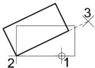
text_image
2 1 3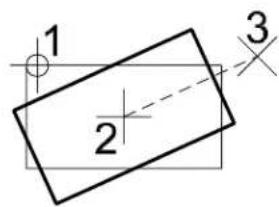
text_image
1 2 3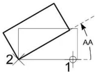
text_image
2 1 AA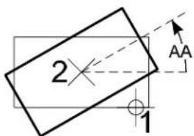
text_image
2 1 AA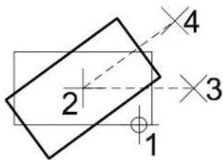
text_image
2 1 3 44-42 MicroStation User Guide
To rotate and stretch elements in a fence
-
Using the Place Fence tool (see page 4-15), place a fence around an element or group of elements.
-
Select the Rotate tool.
The Rotate settings window opens.
- From the Use Fence option menu, choose Stretch.
The Use Fence check box activates, and the Stretch Cells check box also activates.
- On the Method option menu, choose Active Angle and type a value in the angle field.
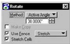
- Enter a data point to define the pivot point.
The elements(s) are rotated and stretched by the Active Angle.
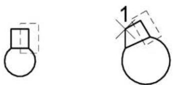
natural_image
Two simple line drawings of geometric shapes: a rounded rectangle and a circular shape, with no text or symbols present.Rotating and stretching elements in a fence using the Rotate tool. Enter a data point (1) to define the pivot point about which the element(s) are rotated and stretched.
To graphically rotate and stretch elements in a fence
- Using the Place Fence tool (see page 4-15), place a fence
around an element or group of elements.
- Select the Rotate tool.
The Rotate settings window opens.
- From the Use Fence option menu, choose Stretch.
The Use Fence check box activates, and the Stretch Cells check box also activates.
- On the Method option menu, choose 2 Points.
(If you choose 3 Points, go to step 7).
-
Enter a data point to define the pivot point.
-
Enter a data point to graphically define the angle of rotation.
Skip to step 10.
-
If Method is set to 3 Points, enter a data point to define the pivot point.
-
Enter a data point to define the start of rotation.
-
Enter a data point to graphically define the angle of rotation.
-
The element(s) are graphically rotated and stretched; repeat to rotate and stretch the element(s) again.
Graphically rotating and stretching elements in a fence (2 Points). Enter a data point (1) to define the pivot point. Enter a d a t a p o (2) tto graphically define the rotation angle.
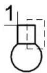
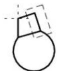

Graphically rotating and stretching elements in ne (3 Points). Enter a data point (1) to define the pivot point. Enter a data point (2) to define the start of rotation. Enter a data point (3) to graphically define the rotation angle.
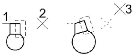
text_image
1 2 ×3To rotate an element by the Active Angle about its center
- Select the Rotate tool.
- Set Method to Active Angle and set the required angle.
- Turn on About Element Center (in the Extended Information section of the tool settings).
- Identify the element to be rotated.
The rotation is displayed dynamically. - Accept to complete the rotation.
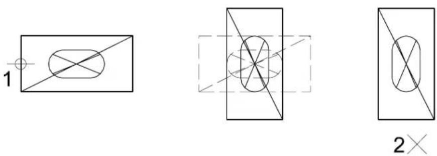
With Method set to Active Angle, and About Element Center turned on: Left: Identify the element (1) — a cell in the illustration. Center: The rotation displays dynamically. Right: Accept (2) to complete the rotation about the center of the element.
To rotate a group of elements by the Active Angle about their centers
- Select the elements with the Element Selection tool, Power Selector, or by placing the fence around them.
- Select the Rotate tool.
- Set Method to Active Angle and set the required angle.
- Turn on About Element Center (in the Extended Information section of the tool settings).
- Enter a data point to complete the rotation.
Left: Selecting the elements to rotate with ne. Right: After rotating elements about their centers.
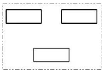
natural_image
Simple diagram with three empty rectangular boxes inside a dashed border (no text or symbols)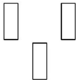
natural_image
Three empty rectangular shapes arranged in a Y-shape (no text or symbols)Key-in: ROTATE ICON
Key-in: FENCE [ROTATE | SPIN] [COPY | ORIGINAL | POINTS] [COPY | ORIGINAL]

If Use Fence is on and the rotation is repeated, any element(s) inside the moved fence are copied along with the original fence contents. It is usually easier to use the Construct Array tool (see page 4-52) with Array Type set to Polar to make multiple rotated copies.
Mirror

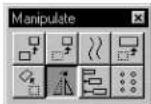
Used to mirror an element(s).
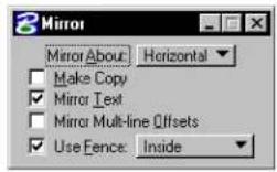
| Tool Setting | Effect |
| Mirror About | Sets direction in which element(s) are mirrored: Horizontal—about horizontal axis.Vertical—about vertical axis.Line—about line defined by two data points. |
| Make Copy | If on, the element(s) are copied and the copy(s) mirrored; the original(s) are not manipulated. |
| Mirror Te x t | If on, text is mirrored. |
| Mirror Multi-line Offsets | If on, multi-line profile offsets are mirrored. |
| Use Fence | If on, the fence contents are mirrored. The option menu sets the Fence (Selection) Mode. |
To mirror an element(s)
- Select or fence the element(s).
- Select the Mirror tool.
- Enter a data point.
If Mirror About is set to Horizontal or Vertical, the element(s) are mirrored. You can repeat step 3 to mirror the element(s) again.
If Mirror About is set to Line, this data point defines one point on the mirroring line.
- If Mirror About is set to Line, enter another data point to
define another point on the mirroring line.
The element(s) are mirrored. You can go back to step 3 to mirror the element(s) again.
Alternative method — To mirror an element(s)
- Select the Mirror tool.
- Identify the element.
- Follow steps 3 and 4 above.
Mirror tool. Clockwise from top left: Mirror About Horizontal, Vertical, and Line. Mirror Text is on.
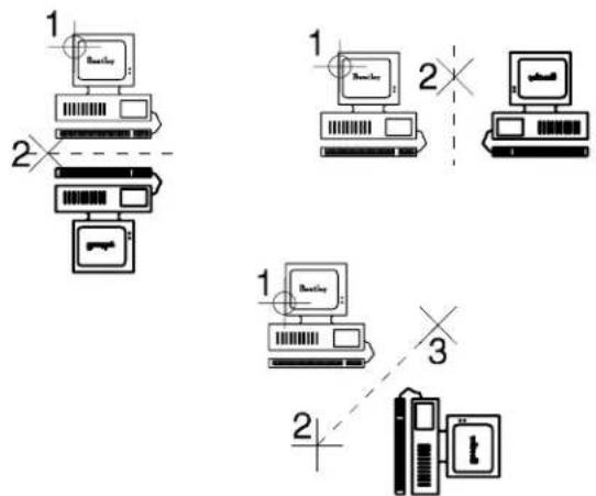
flowchart
graph TD
    A["1: Breakfast"] --> B["2: Bus"]
    B --> C["3: Laptop"]
    C --> D["1: Breakfast"]
    D --> E["2: Bus"]
    E --> F["3: Laptop"]
    style A fill:#f9f,stroke:#333
    style B fill:#ccf,stroke:#333
    style C fill:#cfc,stroke:#333
    style D fill:#fcc,stroke:#333
    style E fill:#cff,stroke:#333
    style F fill:#ffc,stroke:#333
Key-in: MIRROR ICON
Key-in: FENCE MIRROR [COPY | ORIGINAL] [HORIZONTAL | LINE | VERTICAL]
Align Edges


Used to align an element(s) to an edge of another element.
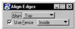
| Tool Setting | Effect |
| Align | Sets the manner by which to align:TopBottomLeftRightHoriz(ontal) CenterVert(ical) CenterBoth Centers |
| Use Fence | If on, the fence contents are aligned. The option menu sets the Fence (Selection) Mode. |
To align elements to another element
- Select or fence the elements to align.
- Select the Align Edges tool.
- Identify the base element to which to align the selected elements.
The selected elements are aligned to the edge of the base element. - Accept the alignment to the base element.
Alternative method — To align elements to another element
- Select the Align Edges tool.
- Identify the base element to which to align other elements.
The base element highlights, and a range block is displayed normal to the view. - Identify an element to align.
The identified element is aligned to the edge of the base element, which remains highlighted with the range block. - Continue identifying elements until all of the desired elements are aligned to the base element.
- Accept the last element's alignment to the base element.
The base element remains highlighted with the range block. - Reset.
Key-in: ALIGNEDGE
Construct Array

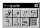
Used to copy an element(s) many times to create an array.
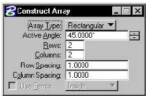
text_image
Construct Array Array Type: Rectangular Active Angle: 45.0000° Rows: 2 Columns: 2 Flow Spacing: 1.0000 Column Spacing: 1.0000 Use Fence: Inside| Tool Setting | Effect |
| Array Type | Set the type of array that is constructed; different settings are available depending on how this is set.Rectangular—Construct a Rectangular arrayPolar—Construct a Polar (circular) array |
| Use Fence | If on, the fence contents are copied into an array.The option menu sets the Fence (Selection) Mode. |
| Active Angle | (Rectangular array type) Aligns the imaginary orthogonal grid on which the copies are placed. |
| Rows | (Rectangular array type) The number of rows. |
| Columns | (Rectangular array type) The number of columns. |
| Row Spacing | (Rectangular array type) The space between rows. ^1 |
| Column Spacing | (Rectangular array type) The space between columns. ^1 |
tool
| Tool Setting | Effect |
| Items | (Polar array type) Sets the number of items or copies of the fence contents in the array, including the original. |
| Delta Angle | (Polar array type) Sets the angle between items.If positive, copies are placed counterclockwise.If negative, copies are placed clockwise. |
| Rotate Items | (Polar array type) If on, the element(s) are rotated about the center of the array. |
1 Row and column spacing are measured from the lower left corner of a linear element or the center of a circle or ellipse.
To create a geometric array
- Select conference the element(s).
The element(s) become the lower left items of the array.
- Select the Construct Array tool.
- In the Tool Settings window, set Array Type to Rectangular.
- (Optional) — As needed, adjust other settings.
- Accept the array.
Alternative method — To create a rectangular array
- Select the Construct Array tool.
- In the Tool Settings window, set Array Type to Rectangular.
- Identify the element.
The element becomes the lower left element of the array.
- Follow steps 4–5 above.
Constructing a rectangular array. "D1" denotes the Row Spacing, "D2" the Column Spacing, and "AA" the Active Angle. Left and center: Identifying an element Right: Copying the fence contents with Use Fence on.
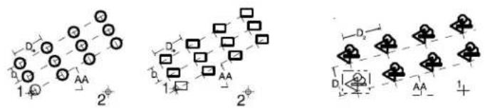
chemical
Molecular orbital diagrams showing electron density distributions with labeled orbitals and distancesTo create a polar array
- Select or fence the element(s).
- Select the Construct Array tool.
- In the Tool Settings window, set Array Type to Polar.
- Enter a data point to define the array's center.
Alternative method — To create a polar array
- Select the Construct Array tool.
- In the Tool Settings window, set Array Type to Polar.
- Identify the element to copy.
- Enter a data point to define the array's center.
The point at which the element is identified (step 3) is positioned in each copy on an imaginary circle.
Constructing
a p o l a r
array. Top:
Identifying an element.
Number of
Items is 8 and
Delta Angle is 45^ . Bottom:
Copying fence contents (Use Fence on).
Number of Items is 6 and Delta Angle is 60.
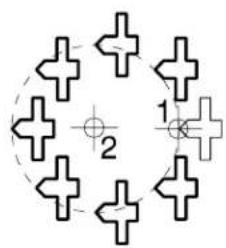
natural_image
Pure geometric diagram with cross shapes and numbered labels (no text or symbols)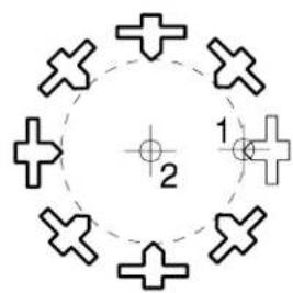
natural_image
Circular diagram with eight cross symbols and a central point, no text or labels present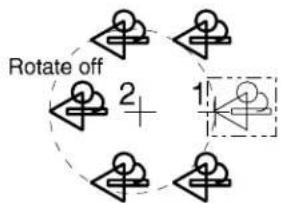
flowchart
graph TD
    A["Step 1"] --> B["Rotate off"]
    B --> C["Step 2"]
    C --> D["+"]
    D --> E["Step 3"]
    E --> F["Step 4"]
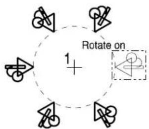
text_image
Rotate on 1 +Key-in: ARRAY ICON
Key-in: FENCE ARRAY [RECTANGULAR | POLAR]
Change Attributes tool box
These tools in the Change Attributes tool box are used to change an element(s) to the active element attribute settings.
| To | Select in the Change Attributes tool box |
| Change an element(s) level, color,line style, line weight, or class. |  Change Element Attributes(see page 4-58) Change Element Attributes(see page 4-58) |
| Change a closed element(s) to theactive area (Solid or Hole). |  Change Element to Active Area (see page 4-61) Change Element to Active Area (see page 4-61) |
| Change a closed element(s) tothe Active Fill Type. |  Change Element to Active FType (see page 4-63) Change Element to Active FType (see page 4-63) |
| Interactively modify the line styleattributes of an element with acustom line style. |  Modify Line tSle Attributes(see page 4-64) Modify Line tSle Attributes(see page 4-64) |
| Change a multi-line to themulti-line definition. |  Change Multi-line to Active Definition (see page 4-67) Change Multi-line to Active Definition (see page 4-67) |
| Set the active element attributes sothey match those of an existingelement. |  Match Element Attributes (sepage 4-68) Match Element Attributes (sepage 4-68) |
Element Manipulation and Modification Tools
Change Attributes tool box
| To | Select in the Change Attributes tool box |
| Change all active element attribute settings, including those specific to particular element types, so they match the attributes of an element in the design. |  Match All Element Settings (SmartMatch) (see page 4-69) Match All Element Settings (SmartMatch) (see page 4-69) |
Key-in: DIALOG TOOLBOX CHANGE [OFF | ON | TOGGLE]

These tools are used to change other element-specific attributes:
| To change attributes for | Use |
| B-spline curves |  Change to Active Curve Settings (see page 7-110) in the Modify Curves tool box. Change to Active Curve Settings (see page 7-110) in the Modify Curves tool box. |
| B-spline surfaces |  Change to Active Surface Settings (see page 8-195) in the Modify Surfaces tool box. Change to Active Surface Settings (see page 8-195) in the Modify Surfaces tool box. |
| Dimension elements |  Change Dimension to Active Settings in the Dimension tool box in the Guide to Generating Drawings. Change Dimension to Active Settings in the Dimension tool box in the Guide to Generating Drawings. |
| Text elements |  Change Text Attributes in the Text tool box in the Guide to Generating Drawings. Change Text Attributes in the Text tool box in the Guide to Generating Drawings. |
Change Element Attributes

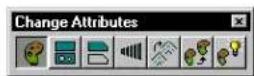
Used to change selected attributes of an element(s). Change Element Attributes tool settings are used to specify the new attribute settings. The controls that affect attribute settings are similar to those in the Element Attributes dialog box (Element menu > Attributes).
The Change Element Attributes tool is efficient for changing the level of an element to a level that is currently turned off (the effect of "sending" an element to another level) without changing the active attributes. Also, since it allows you to match and change attributes using the same tool, Change Element Attributes is very useful when you are doing repetitive changes to many different elements (like going though an entire drawing cleaning up line weights).
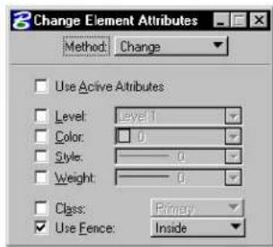
text_image
Change Element Attributes Method: Change Use Active Attributes Level: Level 1 Color: 0 Style: 0 Weight: 0 Class: Primary Use Fence: InsideElement Manipulation and Modification Tools
Change Element Attributes
| Tool Setting | Effect |
| Method | Sets whether you want to change or match and change selected element attributes.Change—Changes selected attributes of an element.Match / Change—If Use Active Attributes is on, first matches the active element attributes to the attributes of the selected element, then changes the next element you select to match the newly changed active element attributes.If Use Active Attributes is off, first matches an element's attributes to the next selected element's attributes, then changes still the next selected element to match the newly changed element's attributes. |
| Use Active Attributes | If on, the active attributes are affected when you change or match attribute settings.If off (the default), the active attributes are not affected when you change or match attribute settings. |
| Level Active Level, if Use Active Attributes is on. | |
| Color Active Color, if Use Active Attributes is on. | |
| Style Active Line Style (and any active line style modifiers), if Use Active Attributes is on. | |
| Weight | Active Line Weight, if Use Active Attributes is on. |
| Class Active Class — Primary or Construction, if Use Active Attributes is on. | |
| Use Fence | If on, the selected attributes of the fence contents are changed. |
To change an element's attributes (those that are set to on)
- Select the Change Element Attributes tool.
-
Set Method to Change.
-
Turn on Use Active Attributes to change an element's attributes to match the active element attribute settings. or
Turn off Use Active Attributes to change an element's attributes without using or affecting the active element attribute settings.
-
Identify the element.
-
Accept the change.
To set the active element attributes so they match those of an element in the design, then change another element's attributes based on the active element attributes
-
Select the Change Element Attributes tool.
-
Set Method to Match / Change.
-
Turn on Use Active Attributes.
-
Identify the element to match.
-
Turn on the attributes you want to change in the next element(s) selected.
-
Select or fence the element(s).
-
Accept the change.
To match the element without affecting the active element attributes to an element in the design, then change another element's attributes based on the active element attributes
-
Select the Change Element Attributes tool.
-
Set Method to Match / Change.
-
Turn on Use Active Attributes.
-
Identify the element to match.
-
Turn on the attributes you want to change in the
next element(s) selected.
- Select or fence the element(s).
- Accept the change.
Key-in: CHANGE ICON
Key-in: FENCE CHANGE <CLASS|COLOR|LEVEL
| STYLE | WEIGHT

To change the Active Color, Active Line Style, or Active Line Weight and the corresponding attribute of the selected element(s) in one step, use the c controls in the Attributes tool box.
For more information on changing element attributes, see the "Attributes" tool box in the online Reference Guide.

To set the active element attributes so they match those of an element in the design, you can also use the Match Element Attributestool.
For more information on matching element attributes see the
"Match Element Attributes tool" on page 4-68.
Change Element to Active Area

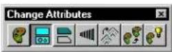
Used to change the area attribute of a closed element(s) (shapes, ellipses, complex shapes, or B-spline curves) to the Active Area.
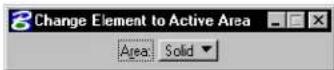
| Tool Setting | Effect |
| Area | Sets the Active Area.· If Solid, element's Area attribute is changed to Solid.· If Hole, element's Area attribute is changed to Hole. |
To change an element to the active area
- Select the closed element(s).
- Select the Change Element to Active Area tool.
Alternative method — To change an element to the active area
- Select the Change Element to Active Area tool.
- Identify the closed element.
- Accept the change.
Key-in: CHANGE AREA
To associate a solid element with a set of holes, use the Group Holes tool (see page 7-25) in the Groups tool box.
It is not possible to pattern an element with the area attribute of Hole.
Change Element to Active Fill Type

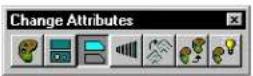
Used to change a closed element (shape, ellipse, complex shape, or B-spline curve) to the Active Fill Type.
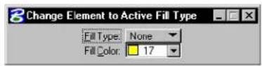
| Tool Setting | Effect |
| Fill Type | Active Fill (see page 2-13) Type — None (no fill), Opaque (filled with Active Color (see page 2-2)), or Outlined. |
| Fill Color | Sets color with which the element(s) are filled.If Fill Type is Opaque, the element(s) are filled with the Active Color, which is also the color of the element's outline.If Fill Type is Outlined, the element(s) can be filled with a color that is different from the Active Color. |
To change an element to the Active Fill Type
- Select the closed element(s).
- Select the Change Element to Active Fill Type tool.
Alternative method — To change an element to the Active Fill Type
- Select the Change Element to Active Fill Type tool.
- Identify the closed element.
- Accept the change.
Key-in: CHANGE FILL

To display fill in a view, turn on Fill (see page 2-13) for the view in the View Attributes dialog box (opened by choosing View Attributes from the Settings menu).

These key-ins let you change a single color attribute:
| To change Key in | |
| An element's outline to the Active Color (see page 2-2). | CHANGE COLOR OUTLINE |
| A filled element's fill to the Active Fill Color (see page 2-13). | CHANGE COLOR FILL |
Modify Line Style Attributes

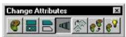
Used to interactively modify the line style attributes of an element with a custom line style. The tool setting Method determines the type of modification.
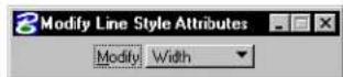
| Method Used | to modify |
| Width The starting | ing, or Origin, width and the End width of an element. |
| Start Width | The starting, or Origin, width of an element. |
| End Width The | e End width of an element. |
| Scale The Sc | ale Factor applied to strokes. |
| Dash Scale The | Scale Factor applied to variable length dash strokes. |
| Gap Scale | Scale Factor applied to variable length gap strokes. |
| Shift | The Shift distance by which the stroke pattern is shifted relative to the beginning of an element or its segments. |
To modify an element's line style attributes
- Select the Modify Line Style Attributes tool.
- Identify the element.
The movement of the pointer shows the direction and extent of the change that will occur upon entry of the next data point.
- Accept the change.
Key-in: MODIFY LINESTYLE ICON
Key-in: MODIFY LINESTYLE <DASHSCALE| ENDWIDTH | GAPSCALE | SCALE | SHIFT | STARTWIDTH | WIDTH
CHANGE LINESTYLE SCALE
The CHANGE LINESTYLE SCALE key-in is used to scale an element's (custom) line style by a specific factor — for example, CHANGE LINESTYLE SCALE 2.0. The specified scale factor has the same effect as the Scale Factor setting in the Line Styles dialog box. If you do not specify a factor, a factor of 1.0 is assumed.
To scale an element's (custom) line style by a specific factor
- Select the element(s).
- Key in CHANGE LINESTYLE SCALE [scale_factor].
Alternative method — To scale an element's (custom) line style by a specific factor
- Key in CHANGE LINESTYLE SCALE [scale_factor].
- Identify the element.
- Accept the element.
To scale the (custom) line style of elements contained in the fence by a specific factor
- Place the fence and set the Fence (Selection) mode appropriately.
- Key in CHANGE LINESTYLE SCALE [scale_factor].
- Accept the fence contents.
ACTIVE LINESTYLESCALE
The ACTIVE LINESTYLESCALE key-in is use to set the global scale factor for custom line styles. The specified scale factor has the same effect as the Scale Factor setting in the Line Styles dialog box.
To set the active line style scale for custom line styles
- Key in ACTIVE LINESTYLESCALE 5
All custom line styles now will be placed at 5 times their normal scale.
Key-in: ACTIVE LINESTYLESCALE
Change Multi-line to Active Definition

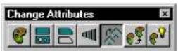
Used to change a multi-line's attributes to the active multi-line definition, which can be set as follows:
- In the Multi-lines dialog box (opened by choosing Multi-lines from the Element menu). For more information on Multi-Lines see “Multi-lines” in the Reference Guide.
- Select a Multi-line settings group component in the Select Settings window (opened by choosing Manage from the Settings menu). For more information on managing multiline settings, see "Manage" in the Reference Guide.
To change a multi-line to the active multi-line definition
- Select the multi-line(s).
- Select the Change Multi-line to Active Definition tool.
Alternative method — To change a multi-line to the active multi-line definition
- Select the Change Multi-line to Active Definition tool.
- Identify the multi-line.
- Accept the change.
Key-in: CHANGE MLINE
√ The active multi-line definition can be set to match a multi-line element
with the Match All Element Settings (SmartMatch) tool (see page 4-69).
Match Element Attributes

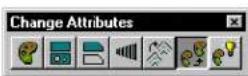
Used to change the active element attribute settings so they match the attributes of an element in the design.
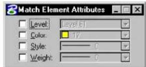
text_image
Match Element Attributes Level: Level 5 Color: 17 Style: 0 Weight: 0| Tool Setting | Effect |
| Level Active Level (see page 1-2) | |
| Color Active Color (see page 2-2) | |
| Style Active Line Style (see page 2-6) | |
| Weight Active Line Weight (see page 2-4) | |
To match an element's attributes (those that are on)
- Select the element.
- Select the Match Element Attributes tool.
- Accept the new active element attributes.
Alternative method — To match an element's attributes (those that are on)
- Select the Match ElementAttributes tool.
- Identify the element.
- Accept the new active element attributes.
Key-in: MATCH ICON
Key-in: MATCH [COLOR | LEVEL | STYLE | WEIGHT]

To match all element attribute settings, including those that are specific to an element type such as dimension or text, use the Match All Element Settings (SmartMatch) tool (see page 4-69).

To change the color, line style, line weight, or level of an element(s) to the active element attributes, use the Change Element Attributes tool (see page 4-58).
Match All Element Settings

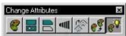
Used to change all active element attribute settings, including those specific to particular element types, so they match the attributes of an element in the design. When a cell is matched, the active scale factors and Active Cell are also matched.
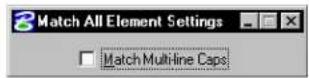
| Tool Setting Effect | |
| Match Multi-line Caps | If on, multi-line caps settings are matched as well. |
To match an element's attributes
- Select the element.
- Select the Match All Element Settings tool.
Alternative method — To match an element's attributes
- Select the Match All Element Settings tool.
- Identify the element.
- Accept the new active settings.
Key-in: MATCH ELEMENT
This tool is also referred to as SmartMatch.
To change the color, line style, line weight, or level of an element(s) to the active element attributes, use the Change Element Attributes tool (see page 4-58).
Match tool box
The tools in the Match tool box are used to set element attribute settings to those of an element in the design (or a reference), making it easy to place elements with the same attributes as existing elements.
| To | Select in the Match tool box |
| Change all active element attribute settings, including th o s e spec i f i c t o p a r ti element types, so they match the attributes of an element in the design. |  Match All Elemt Settings (SmartMatch) (see page 4-69) ^1 Match All Elemt Settings (SmartMatch) (see page 4-69) ^1 |
| Set the active element attributes so they match those of an existing element. |  Match Element Attributes (see page 4-68) ^1 Match Element Attributes (see page 4-68) ^1 |
| Set the active text settings t h e s a m e he corresponding attributes of text in the design. |  Match Text Attributes (see page 4-72) ^2 Match Text Attributes (see page 4-72) ^2 |
| Set the active multi-line definition to the definition of a multi-line element. |  Match Multi-line Definition (see page 4-73) Match Multi-line Definition (see page 4-73) |
| Set the active dimension settings to the dimension attributes of a dimension element. |  Match Dimension Settings (see page 4-74) Match Dimension Settings (see page 4-74) |
| Set the active pattern settings to match the attributes of a pattern element. |  Match Pattern Attributes (see page 5-63) ^3 Match Pattern Attributes (see page 5-63) ^3 |
| Match the active B-spline curve settings to the attributes of a B - s p l i n e c u r v e. |  Match Curve Settings (see page 4-75) Match Curve Settings (see page 4-75) |
| Match the active B-spline surface settings to the attributes of a B-spline surface. |  Match Surface Settings (see page 4-76) Match Surface Settings (see page 4-76) |
1 Also in the Change Attributes tool box.
2 Also in the Text tool box.
3 Also in the Patterns tool box.
Key-in: DIALOG TOOLBOX MATCH[OFF | ON | TOGGLE]
Match TextAttributes

Used to set the active text settings (such as Justification, Font, Line Spacing Type, Line Length, Underline, Vertical, Slant Angle, and Inter Character Spacing) the same as the corresponding attributes of text in the design.
To set the active text settings to those of existing text
- Select one text element.
- Select the Match Text Attributes tool.
Key-in: ACTIVE TEXT
The active text settings are set in the Text Styles dialog
box (Element menu >Text Styles).
Match Multi-line Definition

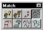
Used to set the active multi-line definition (all settings that can be set in the Multi-lines dialog box) to the definition of a multi-line element.
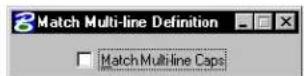
| Tool Setting Effect | |
| Match Multi-Line Caps | If on, multi-line caps settings are matched as well. |
To match the active multi-line definition
- Select the multi-line element.
- Select the Match Multi-line Definition tool.
Alternative method — To match the active multi-line definition
- Select the Match Multi-line Definition tool.
- Identify the multi-line element.
- Accept the new active multi-line definition.
Key-in: MATCH MLINE

To change a multi-line to the active multi-line definition, use the Change Multi-line to Active Definition tool (see page 4-67) in the Change tributes tool box.
Match Dimension Settings

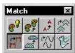
Used to set the active dimension settings to the dimension attributes of a dimension element.
To match dimension settings
- Select the dimension element.
- Select the Match Dimension Settings tool.
Alternative method — To match dimension settings
- Select the Match Dimension Settings tool.
- Identify the dimension element.
- Accept the new active dimension settings.
Key-in: MATCH DIMENSION

To change a dimension to the active dimension attributes, use the
Change Dimension to Active Settings tool in the Dimension tool box.
Match Curve Settings

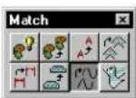
Used to change the active B-spline curve settings to the B-spline attributes of a B-spline curve in the design.
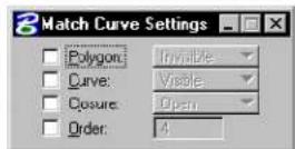
| Tool Setting | Effect |
| Polygon | If on, whether the curve's control polygon is displayed is matched.Invisible—the control polygon is not displayed.Visible—the control polygon is displayed. |
| Curve | If on, whether the curve is displayed is matched:Invisible—the curve is not displayed.Visible—the curve is displayed. |
| Closure If | on, whether the B-spline is Open or Closed is matched. |
| Order | If on, the order of the identified curve is matched. |
To match the active curve settings
- Select the B-spline curve.
- Select the Match Curve Settings tool.
Alternative method — To match the active curve settings
- Select the Match Curve Settings tool.
- Identify the B-spline curve.
- Accept the new active B-spline curve settings.
Key-in: MATCH CURVE
To change a B-spline curve to the active B-spline attributes, use the Change to Active Curve Settings (see page 7-110) tool in the Modify Curves tool box.
Match Surface Settings

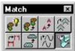
Used to change the active B-spline surface settings to the attributes of a B-spline surface in the design.
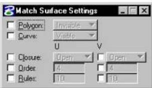
text_image
3 Match Surface Settings Polygon: Invisible Curve: Visible U V Closure: Open Open Order: 4 9 Rules: 10 10| Tool Setting | Effect |
| Polygon If | on, whether the surface's control polygon is displayed is matched.Invisible—the control polygon is not displayed.Visible—the control polygon is displayed. |
| Curve | If on, whether the surface is displayed is matched:Invisible—the surface is not displayed.Visible—the surface is displayed. |
| Closure | If on in the U or V direction, whether the surface is Open or Closed in that direction is matched. |
| Order If on | in the U or V direction, the order of the identified surface in that direction is matched. |
| Rules | If on in the U or V direction, the number of rule lines in that direction is matched. |
To match the active surface settings
- Select the B-spline surface.
- Select the Match Surface Settings tool.
Alternative method — To match the active surface settings
- Select the Match Surface Settings tool.
- Identify the B-spline surface.
- Accept the new active B-spline surface settings.
Key-in: MATCH SURFACE

To change a B-spline surface to the active B-spline surface attributes, use the Change to Active Surface Settings tool (see page 8-195) in the Modify Surfaces tool box.
Drop tool box
The tools in the Drop tool box are used to break up complex elements into simpler components, and to remove association points between elements.
| To | Select in the Drop tool box |
| Break up a complex element(s) or an element(s) of a special type into simpler components. |  Drop Element (see page 7-10) Drop Element (see page 7-10) |
| Break up a complex element into its components. |  Drop Complex Status (see page 4-80) Drop Complex Status (see page 4-80) |
| Convert a line string or shape to a series of individual line elements. |  _D r o p L i n e S t r i n g / S h a p e (see page 4-81) _D r o p L i n e S t r i n g / S h a p e (see page 4-81) |
| Convert the text characters in a t e x t e l enmto the individual elements that are used to draw the characters. |  _Drop Text (see page 4-82) _Drop Text (see page 4-82) |
| Discontinue an association between a shared cell, dimension witness line, or multi-line and another element. |  _Drop Association (see page 4-83) _Drop Association (see page 4-83) |
Element Manipulation and Modification Tools
Drop tool box
| To | Select in the Drop tool box |
| Remove (drop) an element(s) from a graphic group. or Break up a graphic group into individual elements. |  Drop from Graphic Group (see page 7-23) ^1 Drop from Graphic Group (see page 7-23) ^1 |
| Convert an element with a custom line style to an identically appearing group of primitive elements with standard line styles. |  Drop Line Style (see page 4-84) Drop Line Style (see page 4-84) |
| Convert any associative pattern (or hatch) into an identically appearing group of primitive elements. |  Drop Associative Pattern (see page 4-85) Drop Associative Pattern (see page 4-85) |
| Convert a multi-line to a set of line strings, lines, and/or arcs. |  Drop Multi-line (see page 4-86) Drop Multi-line (see page 4-86) |
| Break up a dimension element(s) into their components. |  Drop Dimension Element (see page 4-87) Drop Dimension Element (see page 4-87) |
1 also in the Groups tool box.
Key-in: DIALOG TOOLBOX DROP [OFF | ON | TOGGLE]
![Bentley MicroStation V8 - Key-in: DIALOG TOOLBOX DROP [OFF | ON | TOGGLE] - 1](/content/2026/02/423073/images/1ebd9481d39d0984b2473f83829016735da59ef51887104799ec244d3d427e6b.jpg)
The Drop Element tool (see page 7-10) is a general dropping tool. It incorporates the capabilities of several of the more specialized tools in the tool box.
Drop Complex Status

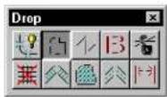
Used to break up a complex element (cell, complex chain, complex shape, text node, surface, or solid) into its components. The components can then be manipulated individually.
To break up a complex element into its components
- Select the complex element(s).
- Select the Drop Complex Status tool.
The tool has no effect on selected elements that are not complex elements. If none of the selected elements is a complex element, the message "Nothing to drop" is displayed in the status bar.
Alternative method — To break up a complex element into its components
- Select the Drop Complex Status tool.
- Identify the complex element.
- Accept the drop.
Key-in: DROP COMPLEX
The Drop Complex Status tool cannot be used to disassociate a B-spline curve from its control polygon.
√ To quickly break up many complex elements, place the fence and use
the Drop Complex Status of Fence Contents tool (see page 4-24).
Drop Line String/Shape Status

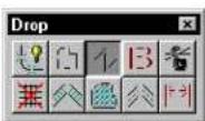
Used to convert a line string or shape to a series of individual line elements.
To convert a line string or shape to individual line elements
- Select the line string(s) or shape(s).
- Select the Drop Line String/Shape Status tool.
The tool has no effect on selected elements that are not line strings or shapes. If none of the selected elements is a line string or shape, the message "Nothing to drop" is displayed in the status bar.
Alternative method — To convert a line string or shape to individual line elements
- Select the Drop Line String/Shape Status tool.
- Identify the line string or shape.
- Accept the drop.
Key-in: DROP STRING
Drop Text

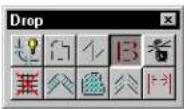
Used to convert the text characters in a text element to the individual elements that are used to draw the characters — lines, line strings, arcs, ellipses, and shapes.
To convert text to individual elements
-
Select the text element(s).
-
Select the Drop Text tool.
The tool has no effect on selected elements that are not text elements. If none of the selected elements is a text element, the message "Nothing to drop" is displayed in the status bar.
Alternative method — To convert text to individual elements
-
Select the Drop Text tool.
-
Identify the text element.
-
Accept the drop.
Key-in: DROP TEXT

To break up a multi-line text element (text node), first use the Drop Complex Status tool to break it up into individual text elements and then use the Drop Text tool on each of the text elements.
Drop Association

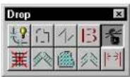
Used to discontinue an association point between a shared cell origin, dimension extension line vertex, or multi-line vertex and another element. The association point is converted to a non-associative origin or vertex with its own x-, y-, and (in 3D) z- coordinates. It is then independent of the other element. For more information about association points, see “Associating Elements” on page 7-50.
To discontinue an association
- Select the Drop Association tool.
- Identify the association point.
- Accept the drop.
To discontinue all association points on an element(s)
- Select the element(s).
- Select the Drop Association tool.
- Accept the drop.
To discontinue all associations in the fence contents
-
Key in FENCE DROP ASSOCIATION.
-
Accept the drop.
Key-in: DROP ASSOCIATION
Drop Line Style

Used to convert any element with a custom line style to an identically appearing group of primitive elements with standard line styles. Dash strokes are converted to line or line string elements. Point symbols are converted to primitive elements but not dropped to individual vectors.
To drop an element with a custom line style
- Select the element.
- Select the Drop Line Style tool.
- Accept the drop.
Alternative method — To drop an element with a custom line style
- Select the Drop Line Style tool.
- Identify the element.
- Accept the drop.
Key-in: DROP LINESTYLE
Drop Associative Pattern

Used to convert any associative patterning or hatching into primitive elements that are no longer associated with the original patterned element. For information about patterning, see "Hatching and Patterning" on page 5-29.
To drop an associative pattern or hatching
- Select the patterned element.
- Select the Drop Associative Pattern tool.
- Accept the drop.
Alternative method — To drop an associative pattern or hatching
- Select the Drop Associative Pattern tool.
- Identify the patterned element.
- Accept the drop.
Key-in: DROP PATTERN
Drop Multi-line

Used to convert a multi-line element to a set of line strings, lines, and/or arcs.
To convert a multi-line to its components
-
Select the multi-line(s).
-
Select the Drop Multi-line tool.
The tool has no effect on selected elements that are not multi-lines. If none of the selected elements is a multi-line, the message "Nothing to drop" is displayed in the status bar.
Alternative method — To convert a multi-line to its components
-
Select the Drop Multi-line tool.
-
Identify the multi-line.
-
Accept the drop.
To drop multi-line elements in the fence contents
-
Key in FENCE DROP MLINE.
-
Accept the drop.
Key-in: DROP MLINE
Drop Dimension Element

Used to break up a dimension element(s) into lines, line strings, ellipses, arcs, and text. For information about dimension elements, see Dimension Elements in the Guide to Generating Drawings.
To break up a dimension element
-
Select the dimension element(s).
-
Select the Drop Dimension Element tool.
The tool has no effect on selected elements that are not dimension elements. If none of the selected elements is a dimension element, the message "Nothing to drop" is displayed in the status bar.
Alternative method—Tobreakupadimension element
-
Select the Drop Dimension Element tool.
-
Identify the dimension element.
-
Accept the drop.
To break up dimension elements in the fence contents
-
Key in FENCE DROP DIMENSION.
-
Accept the drop.
Key-in: DROP DIMENSION
Modify tool box
The tools in the Modify tool box are used to modify element geometry.
| To | Select in the Modify tool box |
| Move a vertex of a linear element. orModify rounded segments of complex chains and complex shapes. orChange rounded segments of complex chains and complex shapes to vertices and vice-versa. orScale a circular arc while maintaining its sweep angle. orMove dimension text. orChange dimension extension line length. orScale a block about the opposite vertex. orChange a circle's radius or the length of one axis of an ellipse. |  Modify Element (see page 4-90) Modify Element (see page 4-90) |
| Delete part of an element. |  Delete Part of Eleme (see page 4-101) Delete Part of Eleme (see page 4-101) |
| Extend or shorten a line. |  Extend Line (see page 4-102) Extend Line (see page 4-102) |
| Extend or shorten two open elements to their intersection. |  Extend Two Elements to Intersection (see page 4-104) Extend Two Elements to Intersection (see page 4-104) |
Element Manipulation and Modification Tools
Modify tool box
| To | Select in the Modify tool box |
| Extendorshortenanopen element intersection with another element. |  Extend Element to Intersection (see page 4-105) Extend Element to Intersection (see page 4-105) |
| Trim a series of elements at their intersection with one or more other elements. |  Trim Element (see page 4-106) Trim Element (see page 4-106) |
| Simultaneously trim or extend multiple elements at their intersection with one or more other elements. |  Intelli Trim (see page 4-107) Intelli Trim (see page 4-107) |
| Insert a vertex in a linear element. |  Insert Vertex (see page 4-113) Insert Vertex (see page 4-113) |
| Delete a vertex from a linear element. |  Delete Vertex (see page 4-115) Delete Vertex (see page 4-115) |
| Construct a circular fillet between two elements. |  Construct Circular Fillet (see page 4-116) ^1 Construct Circular Fillet (see page 4-116) ^1 |
| Construct a chamfer between two lines or adjacent segments of a line string or shape. |  Construct Chamfer (see page 4-118) ^1 Construct Chamfer (see page 4-118) ^1 |
Key-in: DIALOG TOOLBOX MODIFY [OFF | ON | TOGGLE]

To create and "clean up" multi-line intersections, use the tools in the Multi-line Joints tool box (see page 7-32).
Modify Element

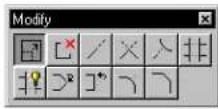
Used to do the following:
- Move a vertex or segment of a line, line string, multi-line, curve, B-spline control polygon, shape, complex chain, or complex shape.
- Scale a block about the opposite vertex.
- Modify rounded segments of complex chains and complex shapes created with the Place SmartLine tool (see page 2-17) while preserving their tangency.
- Change rounded segments of complex chains and complex shapes to sharp and vice-versa.
- Scale a circular arc while maintaining its sweep angle.
- Change a circle's radius or the length of one axis of an ellipse.
- Move dimension text or modify the extension line length of a dimension element.
When used with AccuDraw (see page 3-26), the Modify Element tool becomes even more powerful. The procedures that follow detail the interaction of AccuDraw and the Modify Element tool on various element types.
Elements with multiple segments are line strings, shapes, and complex chains and complex shapes placed with the Place SmartLine tool (see page 2-17). When used with AccuDraw, the Modify Element tool
not only lets you modify vertices and segments, but also lets you change a vertex's type (Sharp, Rounded, or Chamfered).
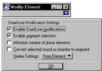
text_image
Modify Element SmartLine Modification Settings Enable SmartLine modifications Enable segment selection Minimize number of linear elements Convert selected round or chamfer to segment Vertex Settings: From Element OK| Tool Setting | Effect |
| Vertex Type | Sets the vertex type.• Sharp• Rounded• Chamfered |
| Round Radius | (with Vertex Type set to Rounded) If on, sets the arc radius for a rounded vertex. |
| Chamfer Offset | (with Vertex Type set to Chamfered) Sets the two distances required to define a chamfer. Chamfer Offset requires that the two chamfer distances be equal (from a theoretical intersection of a midpoint). |
| Orthogonal | If an orthogonal vertex is identified, preserves the orthogonality. |
| Enable Smart-Line modifications | If off, turns off the “smart” behavior, which may be desirable, especially when the element has a very high number of vertices (thousands) causing the tool to slow down considerably. (Note: turning off this setting causes the other options to be disabled, as they only apply to SmartLine style modifications.) |
| Enable segment selection | If off, only allows element modification by individual vertices. |
| Minimize number of linear elements | If off, no longer tries to reduce the number of component elements in a complex chain or shape (lines that can become “compacted” into linestrings, etc.). |
| Convert selected round or chamfer to segment | If on, when selecting a rounded or chamfered vertex, converts the component to a segment (arc or linear segment) so that it can be modified as such. This only applies to the selected round or chamfer, not to the whole chain or shape. After completing the modification, the component will thereafter not be treated as a round or chamfer again. |
| Ver t e x Settings: From Element/Last Used | Choose:From Element—to use the element’s own settings.Last Used—to no longer use the element’s settings. |
To modify an element
- Select the Modify Element tool.
- Identify the element close to the vertex, segment, or axis to modify.
- Enter a data point to make the modification.
Modify Element. Clockwise from top left: moving the endpoint of a line, moving a vertex of a line string, modifying dimension extension line length, moving a vertex of a B-spline control polygon, scaling a block, and changing the radius of a circle.
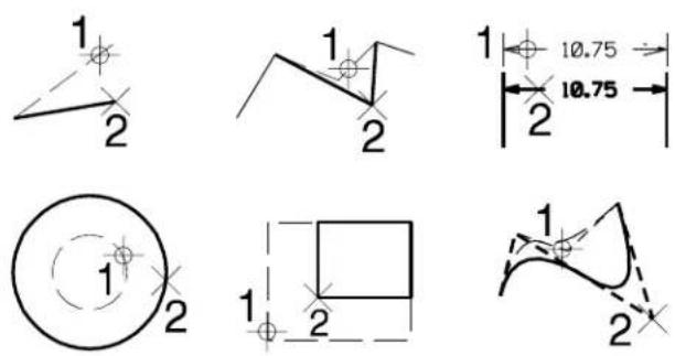
To modify the endpoint of a line
- With AccuDraw active, select the Modify Element tool.
- Enter a data point to identify the end of the line.
The drawing plane origin moves to the opposite end of the line, and the coordinate system aligns its x-axis with the line. Additionally, the length of the line is displayed in the AccuDraw window.
- (Optional) — Rotate the drawing plane axes.
- (Optional) — Preview the modifications by keying in desired changes in the AccuDraw window.
- Enter a data point to complete the modification.
To modify a circle
- With AccuDraw active, select the Modify Element tool.
- Identify the circle.
The drawing plane origin moves to the center of the circle. In addition, the coordinate system switches to Polar,
and aligns with the view axes.
-
(Optional) — Rotate the drawing plane axes.
-
(Optional) — Preview the modifications by keying in a radius value in the AccuDraw window. (When modifying a circle, any value keyed in the AccuDraw window defines a new radius.)
-
Enter a data point to complete the modification.
To modify an ellipse
-
With AccuDraw active, select the Modify Element tool.
-
Identify the ellipse by entering a data point near the axis to modify.
The drawing plane origin moves to the center of the ellipse, and the coordinate system aligns its x-axis with the primary axis of the ellipse.
-
(Optional) — Rotate the drawing plane axes.
-
(Optional) — Preview the modifications by keying in desired changes in the AccuDraw window.
-
Enter a data point to complete the modification.
To modify the sweep angle of an arc
-
With AccuD raw active, select the Modify Element tool.
-
Identify the arc.
-
From the Method option menu in the Tool Settings window, choose Angle.
The drawing plane origin moves to the center of the arc, and the coordinate system aligns its x-axis with the start of the arc's sweep.
-
(Optional) — Rotate the drawing plane axes.
-
(Optional) — Preview the modifications by keying in desired changes in the AccuDraw window.
-
Enter a data point to complete the modification.
Modifying the sweep angle of an arc.
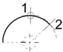

You can adjust the arc sweep by either complement of the angle (180° either way).

To modify the radius of an arc without changing its center point
- With AccuDraw active, select the Modify Element tool.
- Identify the arc.
- From the Method option menu in the Tool Settings window, choose Radius About Center.
The drawing plane origin moves to the center of the arc, and the coordinate system aligns with the view axes.
- (Optional) — Rotate the drawing plane axes.
- (Optional) — Preview the modifications by keying in a radius value in the AccuDraw window. (When modifying an arc, any value keyed in the AccuDraw window defines a new radius.)
- Enter a data point to complete the modification.
Modifying the radius of an arc without changing its center point.
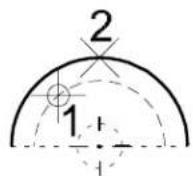
To modify the radius of an arc without changing its endpoints
- With AccuDraw active, select the Modify Element tool.
- Identify the arc.
- From the Method option menu in the Tool Settings window, choose Radius Preserve Ends.
The drawing plane origin moves to the center of the arc, and the coordinate system aligns with the view axes.
- (Optional) — Rotate the drawing plane axes.
- (Optional) — Preview the modifications by keying in a radius value in the AccuDraw window.
- Enter a data point to complete the modification.
Modifying the radius of arc without changing its endpoints.
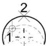
To modify a vertex of a multi-segment element
- With AccuDraw active, select the Modify Element tool.
- Identify the element by entering a data point near the vertex to modify.
The drawing plane origin moves to the vertex, and the coordinate system aligns with the view axes.
- (Optional) — Rotate the drawing plane axes.
- (Optional) — Preview the modifications by keying in desired
changes in the AccuDraw window.
- Enter a data point to complete the modification.
Modifying a chamfered vertex.
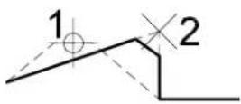
Modifying the vertex of a Linear segment and an Arc segment.
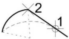
To modify a linear segment of a multi-segment element
-
With AccuDraw active, select the Modify Element tool.
-
Identify the element by entering a data point near the segment's midpoint.
The drawing plane origin moves to the identification point, and the coordinate system aligns its x-axis with the segment.
-
(Optional) — Rotate the drawing plane axes.
-
(Optional) — Preview the modifications by keying in desired changes in the AccuDraw window.
-
Enter a data point to complete the modification.
Modifying a Linear segment.
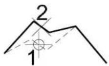
To modify an arc segment of a multi-segment element
-
With AccuDraw active, select the Modify Element tool.
-
Identify the element by entering a data point near the segment's midpoint.
The drawing plane origin moves to the identification point.
-
(Optional) — Preview the modifications by keying in desired changes in the AccuDraw window.
-
Enter a data point to complete the modification.
Modifying an Arc segment.
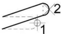
To move a linear segment parallel to itself
-
With AccuDraw active, select the Modify Element tool.
-
Identify the element by entering a data point near the segment's midpoint.
The drawing plane origin moves to the identification point, and
the coordinate system aligns its x-axis with the segment.
-
Position the pointer on the drawing plane's y-axis.
-
Press the Return key.
The movement of the segment is constrained parallel to its current location.
- Enter a data point to complete the modification.
To modify the vertex of orthogonal segments
-
With AccuDraw active, select the Modify Element tool.
-
Identify the element by entering a data point near the vertex to modify.
The drawing plane origin moves to the vertex, and the coordinate system aligns with the segments.
-
(Optional) — Rotate the drawing plane axes.
-
(Optional) — Preview the modifications by keying in desired changes in the AccuDraw window.
-
Enter a data point to complete the modification.
To change a vertex type
-
With AccuDraw active, select the Modify Element tool.
-
Identify the element by entering a data point near the vertex to modify.
The drawing plane origin moves to the vertex. If the vertex is contained within a right angle, the coordinate system aligns with the right angle.
-
From the Vertex Type option menu in the Tool Settings window, choose the desired type — Sharp, Rounded, or Chamfered.
-
If changing Vertex Type to Rounded, key in the desired rounding radius, in working units (MU:SU:PU) in the Tool Settings window's Rounding Radius field.
-
If changing Vertex Type to Chamfered, key in the desired chamfer offset, in working units (MU:SU:PU) in the Tool
Settings window's Chamfer Offset field.
- To maintain the vertex in its original location — that is, to just change its type — enter a data point at the drawing plane origin. or
To otherwise modify the vertex, follow steps 3-5 in the procedure "To modify a vertex of a multi-segment element" on page 4-96.
Key-in: MODIFY ELEMENT

You can modify a line, line string, multi-line, arc, circle, ellipse, curve, shape, text, or complex element by dragging its handles when selected (see "To scale or modify a selected element" on page 3-78 for more information).

To choose SmartLine Modification Settings, click the arrow in the bottom right corner of the Tool Settings window.
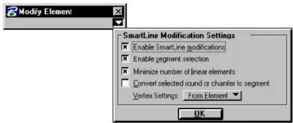
text_image
Modify Element SmartLine Modification Settings Enable SmartLine modifications Enable segment selection Minimize number of linear elements Convert selected round or chanfer to segment Vertex Settings: From Element OK
Tool settings cannot be enabled unless AccuDraw is enabled.

Arc axes cannot be modified with the Modify Element tool. Instead, use the Modify Arc Axis tool (see page 2-74).
Delete Part of Element

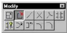
Used to delete part of an element.
- A closed element is turned into an open element — an ellipse or circle becomes an arc; a shape becomes a line string; a closed B-spline curve becomes an open B-spline curve.
- If an interior portion of an open element — line, line string, multi-line, curve, or arc — is partially deleted, the element is divided into two elements of the same type.
To delete part of an element
-
Select the Delete Part of Element tool.
-
Identify the element at one end of the part to delete.
-
For an open element, enter a data point to define the other end of the part to delete.
or For a closed element, enter a data point to define the direction in which to delete. Then enter another data point to define the other end of the part to delete.
Delete Part of Element
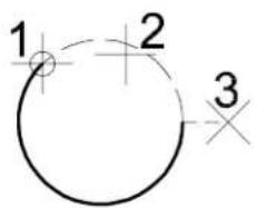
text_image
1 2 3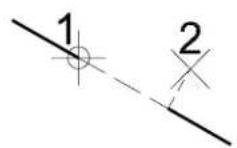
Key-in: DELETE PARTIAL

To delete part of a multi-line, use the Multi-line Partial Delete tool (see page 7-45) in the Multi-line Joints tool box. To make an opening in a multi-line without dividing the multi-line into two elements, use the Cut All Component Lines tool (see page 7-39).
Extend Line

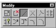
Used to extend or shorten a line or an end segment of a line string or multi-line.
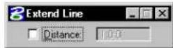
| Tool Setting | Effect |
| Distance | If on, sets the distance.A negative distance shortens the line.A positive distance extends the line. |
To extend or shorten a line by entering a data point
- Select the Extend Line tool.
- Identify the line near the endpoint to modify.
- If Distance is on, accept the modification.
or If Distance is off, enter a data point to define the new endpoint.
Extend Line tool. Top: Defining the new endpoint graphically when Distance is off. Bottom: Defining the new endpoint when Distance is on. If the Distance, denoted by "D," is negative, the line is shortened. If the Distance is positive, the line is lengthened.
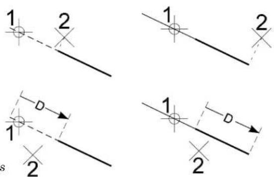
text_image
1 2 1 2 D 1 2 1 2 sKey-in: EXTEND LINE [DISTANCE | KEYIN]

To extend an arc, use the Element Selection tool (see page 4-2) or the Modify Element tool (see page 4-90).
Extend Two Elements to Intersection

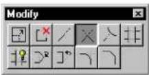
Used to extend or shorten two lines, line strings, or arcs to their intersection.
To extend two elements to their intersection
- Select the Extend Two Elements to Intersection tool.
- Identify the first element.
- Identify the second element.
- Accept the modification.
Extend Two Elements to Intersection tool. Left: Lengthening two lines. Right: Lengthening an arc and shortening a line.
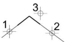
text_image
1 3 2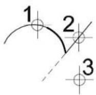
Key-in: EXTEND ELEMENT 2

When an element is shortened, the part of the element that is identified is kept. No modification is made if the identified elements cannot be extended so that they intersect.

To extend two multi-lines to their common intersection, use a tool
in the Multi-line Joints tool box (see page 7-32).
Extend Element to Intersection

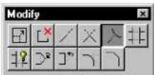
Used to extend or shorten a line, line string, or arc to its intersection with another element.
To extend an element to its intersection with another element
- Select the Extend Element to Intersection tool.
- Identify the element to extend or shorten.
- Identify the element to which the first element will be extended or shortened.
- Accept the modification.
Extend Element to Intersection
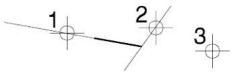
text_image
1 2 3Key-in: EXTEND ELEMENT INTERSECTION
Trim Element

Used to trim or cut an element or series of elements at their intersection with one or more cutting elements. The cutting element and the element that is trimmed can be lines, line strings, arcs, curves, B-spline curves, shapes, ellipses, complex chains, or complex shapes.
To trim an element(s)
- Use the Element Selection tool to select a cutting element(s).
- Select the Trim Element tool.
- Identify an element to trim.
The element is highlighted and how it will be trimmed is dynamically displayed.
- Accept the trimmed element.
- Go back to step 4 to identify another element to trim. or
Reset to finish.
Alternative method — To trim an element(s)
- Select the Trim Element tool.
- Identify the cutting element.
- Follow steps 3–5 above.
Trim Element tool. The cutting elements are indicated by handles.
text_image
Technical diagram showing geometric construction with labeled points and lines, including curved shapes and intersecting curves.Key-in: TRIM

To clean up intersections between multi-lines, use the tools in the Multi-line Joints tool box (see page 7-32).
IntelliTrim

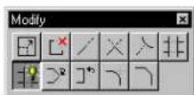
Used to simultaneously trim, extend or cut multiple elements.
The cutting elements or elements to which you can extend other elements are lines, line strings, ellipses, arcs, curves, shapes, complex strings, complex shapes, text nodes, and cell headers.
Elements that can be cut or trimmed are lines, line strings, curves, arcs, ellipses, shapes, B-spline curves, complex strings, and complex shapes.
The only elements that can be extended are lines, line strings, complex
chains that end with a line or line string, and b-spline curves.
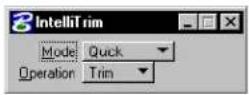
| Tool Setting | Effect |
| Quick Mode | Operation:Trim—If on, elements are trimmed.Extend—If on, elements are extended.Cut—If on, elements are cut. (You will not actually see where the element was cut until you select it.) |
| Advanced Mode | Operation:Toggling between Trim and Extend in Advanced Mode causes all intersections and extension points to be recalculated and displayed.Trim—If on, elements are trimmed.Extend—If on, elements are extended.Cut—Dimmed if Advanced is selected. |
| Select Elements to Trim | If selected, each element that is identified is designated as an element to trim (or extend). |
| Select Cutting Elements | If selected, each element that is identified is designated as a cutting element. |
| Selection Set | Designates selected elements, by default, as:Elements to TrimCutting Elements |
To trim (or extend) multiple elements
-
Select the elements to trim or the cutting elements.
-
Select the IntelliTrim tool.
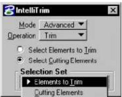
text_image
IntelliTrim Mode Advanced Operation Trim Select Elements to Trim Select Cutting Elements Selection Set Elements to Trim Cutting ElementsIf the tool setting Selection Set is set to Elements to Trim, the selected elements are highlighted.
If Selection Set is set to Cutting Elements, the selected elements are highlighted and dashed.
- If the selected elements are the elements to trim, identify each cutting element.
or
If the selected elements are the cutting elements, identify each element to trim.
All potential cutting points are shown as small dots.
- When done identifying elements, Reset.
The proposed results of the operation are displayed. The trimmable elements remain highlighted to indicate the tentative nature of the display.
-
If the results are satisfactory, Reset to accept them. Otherwise, continue with step 6.
-
For each element whose trim or extension result is not as you desire, enter a data point on the element on or near the part of the element you wish to keep. When entering these guide points, you need not be concerned about "inside" and "outside" (because the cutting elements do not have to be connected or closed).
For each element to trim, the series of entered guide points is evaluated and the part of the element that is closest to the closest guide point is kept. Every time the element crosses a cutting element, it is cut.
- When done modifying the results, Reset.
Alternative method — To trim (or extend) multiple elements
- Select the IntelliTrim tool.
- Identify each element to trim.
- When done identifying elements, Reset.
- Identify each cutting element.
- When done identifying elements, Reset.
The proposed results of the operation are displayed. The trimmable elements remain highlighted to indicate the tentative nature of the display.
-
If the results are satisfactory, Reset to accept them. Otherwise, continue with step 7.
-
For each element whose trim or extension result is not as you desire, enter a data point on the element on or near the part of the element you wish to keep. When entering these guide points you need not be concerned about "inside" and "outside" (because the cutting elements do not have to be connected or closed).
For each element to trim, the series of entered guide points is evaluated and the part of the element that is closest to the closest guide point is kept. Every time the element crosses a cutting element, it is cut.
- When done modifying the results, Reset.
Trimming multiple elements. Top Left: Identify the lements to be trimmed (points 1-4), with a Reset to finish. Top Right: Identify the cutting elements (points 5-6), with Reset to finish. Proposed cutting points appear as small dots. Bottom Left: Reset to display the proposed result. Batom Right: Reverse the result of any incorrect cuts by entering a data point near the part of the element that you wish to kp (point 7). Reset to finish.
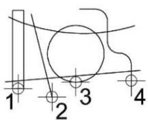
text_image
1 2 3 4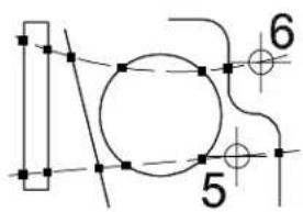
text_image
Technical diagram with numbered components and geometric lines, likely from an engineering or mechanical drawing.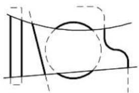
natural_image
Pure geometric line drawing with intersecting curves and shapes (no text or symbols)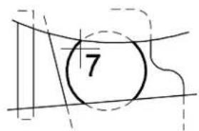
text_image
7Extending multiple elements. Top Left: Identify the lements to be extended (points 1-5), with a Reset to finish. Top Right: Identify the cutting elements (points 6-8), with Reset to finish. Proposed cutting points appear as small dots. Bottom: Reset to display the proposed result. A further Reset completes the operation.
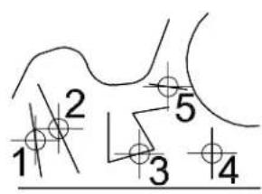
text_image
1 2 3 4 5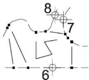
text_image
8 7 6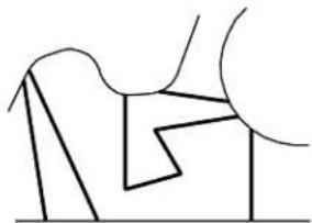
natural_image
Abstract line drawing with geometric shapes and no text or symbolsKey-in: TRIM MULTI

At any point while designating elements, you can switch between identifying elements to trim and identifying cutting elements by selecting the appropriate radio button in the Tool Settings window. If the focus is on one of the radio buttons, you can select the other simply by pressing

To change an element from an element to trim to a cutting element, or vice-versa, simply reidentify it with the corresponding radio button selected. It is possible — and in some cases efficient — to select both the elements to trim and the cutting elements prior to selecting IntelliTrim and then reidentify those elements whose designation is wrong.

If an element cannot be either extended or trimmed, it is deleted under the following condition: there is a cutting element directly between the closest guide point and the element; otherwise the element is not modified.
Insert Vertex

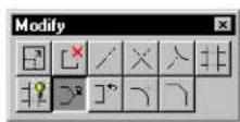
Used to do the following:
- Insert a vertex in a line, line string, multi-line, shape, or B-spline control polygon.
- Attach a line segment to the endpoint of a line or line string.
- Extend a point curve.
- Add an extension line to a dimension element.
To insert a vertex in a line, line string, multi-line, shape, or B-spline control polygon
- Select the Insert Vertex tool.
- Identify the segment on which to add the vertex.
- Enter a data point to position the new vertex.
Using Insert Vertex to insert a vertex in a line string.
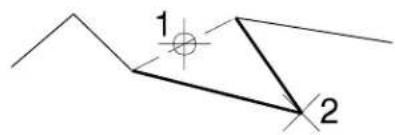
text_image
1 2To attach a line segment to an endpoint of a line or line string
- Select the Insert Vertex tool.
- Enter a data point to define the segment endpoint.
To extend a point curve
- Select the Insert Vertex tool.
- Identify the point curve near the endpoint from which to extend.
- Enter a data point to position the new endpoint (and reposition the identified vertex).
To add an extension line to a dimension element
- Select the Insert Vertex tool.
- Identify the dimension line near the desired extension line location.
- Enter a data point to position the end of the extension line.
Using Insert Vertex to add an extension line to a dimension element.
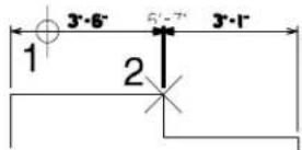
Key-in: INSERT VERTEX

The Insert Vertex tool can be used to change a point element into
a line or a line element into a line string.

A shape or line string can have 5000 vertices.
Delete Vertex

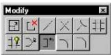
Used to do the following:
- Delete a vertex from a line string, multi-line, shape, or B-spline control polygon.
- Remove an extension line from a dimension element.
To delete a vertex or an extension line
- Select the Delete Vertex tool.
- Identify the vertex or extension line.
- Accept the deletion.
Delete Vertex
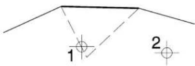
text_image
1 2Key-in: DELETE VERTEX

Deleting a vertex from a line turns it into a point. It is impossible to
delete a vertex from a line string element that has just two vertices.
Construct Circular Fillet

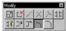
Used to construct a circular fillet (arc) between two elements (lines, line strings, circular arcs, circles, or shapes), two segments of a line string, or two sides of a shape.
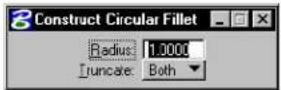
| Tool Setting | Effect |
| Radius | Sets the fillet's radius. |
| Truncate | Sets which side(s) are truncated.None—Neither element or segment is truncated.Both—Both elements or segments are truncated at their point of tangency with the fillet. ^1 First—The first element or segment identified (step 2) is truncated at its point of tangency with the fillet. |
If a fillet is constructed between two closed elements or an open and a closed element, the closed element(s) are not modified.
To construct a circular fillet
-
Select the Construct Circular Fillet tool.
-
Identify the first element or segment.
If Truncate is set to First, this element or segment is truncated.
-
Identify the second element or segment.
-
Accept the fillet and truncation(s), if any.
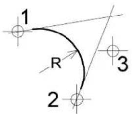
text_image
1 R 2 3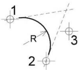
text_image
1 R 2 3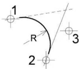
text_image
1 R 2 3Construct Circular Fillet. From left: Truncate set to None, Both, and First.
Key-in: FILLET [MODIFY | NOMODIFY | SINGLE]
In 3D, both elements must be on the same plane to be filleted.
To construct a 3D fillet between two surfaces, use the Blend Surface Between Rail Curves tool (see page 8-207) in the Fillet Surfaces tool box.
To construct a 3D fillet along an edge of a solid, use the Fillet Edges tool (see page 8-138) in the 3D Modify tool box.
Construct Chamfer

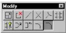
Used to construct a chamfer between either of the following:
- Two lines — The original lines are trimmed and a third line element forms the chamfer.
- Adjacent segments of a line string or shape — An additional vertex is inserted and the common vertex is adjusted to form the chamfer.
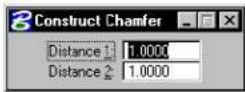
| Tool Setting Effect | |
| Distance 1 | First element or segment identified (step 2). |
| Distance 2 | Second element or segment identified (step 3). |
To construct a chamfer
-
Select the Construct Chamfer tool.
-
Identify the first line or segment.
-
Identify the second line or segment.
If the first data point identifies a line element, the second data point must also identify a line element. If the first data point identifies a segment of a line string or shape, the second data point must identify an adjacent segment of the same element.
- Accept the chamfer.
Chamfer. D1 denotes Distance 1. D2 denotes Distance 2.
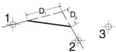
text_image
1 D₁ D₂ 2 3Key-in: CHAMFER

In 3D, both elements must be on the same plane to be chamfered.
text_image
5Using Cells
A cell is a small drawing — usually of a frequently-used or complex symbol, notation, or detail — created in MicroStation. Cells are stored in a DGN file called a cell library, which can contain many cells. Cell Libraries are exactly like DGN files. Any DGN file can be attached as a cell library and any cell library can be opened as a DGN file.
Sample architectural cells
Sample cells for civil engineering
Some sample cells for mapping
Some sample cells for mechanical engineering
natural_image
Pure geometric shapes including circle, cross, arrow, hexagon, triangle, and curved line (no text or symbols)Cells are used for these reasons:
• To save time drawing patterns and repeated details
• To make it easy to update details throughout a DGN file
• To provide uniformity
You can create your own cell libraries.
Each cell has a cell origin, defined when the cell is created, that can be thought of as the cell's "handle." When you enter a data point to place the cell, the origin is placed at that point.
In this chapter, you will find procedures concerning using cells, including:
• Working with Cell Libraries (see page 5-2)
- Creating and Editing Cells (see page 5-6)
- Placing Cells (see page 5-10)
• Using the Tools in the Cells tool box (see page 5-14)
• Hatching and Patterning (see page 5-29)
• Using the Tools in the Patterns tool box (see page 5-39)
• Dimension-driven Cells (see page 5-64)
Working with Cell Libraries
Cell libraries are the same as DGN files. Any DGN file can be attached as a cell library and any cell library can be opened as a DGN file. Each model in a DWG file becomes a separate cell. Cell libraries and DGN files can be used as style libraries.
When you create a cell library, a blank default model is created. This blank model displays when you first open the cell library as a DGN file. You can change to different models
with Models dialog box (File > Models).
Individual DWG files can also be placed as a cell. However, only geometry in the default model is used.
The following describes procedures for creating and attaching a cell library and for browsing cells

Pre-V8 files and cell libraries are not supported as cells. You cannot open a pre-V8 cell library and have it upgrade to a V8 DGN file. It must be attached as a cell library.
To create and attach a cell library
- From the Element menu, choose Cells.
The Cell Library dialog box opens.
- From the File menu in the Cell Library dialog box, choose New.
The Create Cell Library dialog box opens.
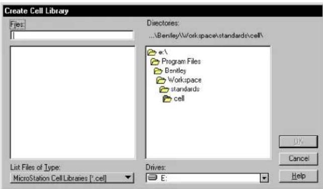
text_image
Create Cell Library Files: Directories: ...\Bentley\Workspace\standards\cell\ e:\ Program Files Bentley Workspace standards cell List Files of Type: MicroStation Cell Libraries (*.cell) Drives: E:-
(Optional) — To select a different destination disk drive, choose the desired drive from the Drives option menu.
-
(Optional) — To select a different destination directory,
use the Directories list box.
- In the Files field, key in a name for the new cell library. By convention, cell library files end in the extension “.cel.”
- Click the OK button.
To attach an existing cell library
- From the Element menu, choose Cells.
The Cell Library dialog box opens.
- From the File menu in the Cell Library dialog box, choose Attach.
The Attach Cell Library dialog box opens.
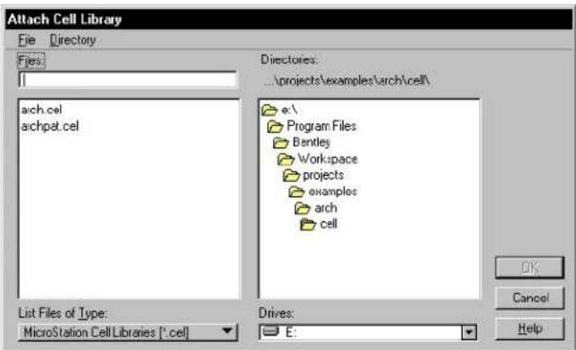
text_image
Attach Cell Library File Directory Files: arch.cel archpet.cel Directories: ...projects\examples\arch\cell\ e:\ Program Files Bentley Workspace projects examples arch cell List Files of Type: MicroStation Cell Libraries (*.cel) Drives: E:- Select the name of the cell library in the Files list box.
- C lick OK.
Alternative method — To attach an existing cell library
- From the Utilities menu, choose Cell Selector.
If there is no cell library already attached, the Select Cell
Library to Load dialog box opens.
-
Select the name of the cell library in the Files list box.
-
Click OK.
The Cell Selector dialog box opens, displaying a tile for each of the available cells in the attached cell library.
To attach a remote cell library
- From the Cell Selector dialog box's File menu, choose Load Remote Cell Library.
See "Select Remote Design File dialog box" in the online Reference Guide for descriptions of the controls in this dialog box.
-
In the URL field, specify the path to the remote cell library.
-
(Optional) — Adjust any other settings necessary.
-
Click OK.
To browse cells
- From the Element menu, choose Cells.
The Cell Library dialog box opens. If a cell library is attached, its name is in the title bar.
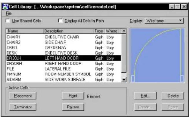
text_image
Cell Library: [...Workspace\system\cell\remodel.cel] File Use Shared Cells Display AI Cells In Path Name Description Type Where CHAIR1 EXECUTIVE CHAIR Gph Lbry CHAIR2 SIDE CHAIR Gph Lbry CRED CREDENZA Gph Lbry DESK EXECUTIVE DESK Gph Lbry DR30LH LEFT HAND DOOR Gph Lbry DR30RH RIGHT HAND DOOR Gph Lbry FILE LATERAL FILE Gph Lbry RMNUM ROOM NUMBER SYMBOL Gph Lbry SIDARM SIDE WORK SURFACE Gph Lbry Active Cells Placement immune Element Terminator Pattern Edit... Delete Create... SpaceIf no cell library is attached and there are no cells in the DGN file, there is nothing to browse. For information about attaching a cell
library, see "To attach a previously existing cell library" on page 5-4.
- In the list box, select the name of a cell.
An image of the cell is displayed to the right of the list box.
- Browse through the cells by selecting other cells with the mouse or by pressing the arrow keys on the keyboard.
As each cell is selected, its image is displayed to the right of the list box.

You can browse the contents of cell libraries when setting the Active Cell using the Place Active Cell settings window. Clicking the magnifying glass icon next to the Active Cell field opens the Cell Library dialog box for browsing.
Creating and Editing Cells
This section covers how to create and edit cells.

Instead of creating cells "from scratch," consider using the cell libraries supplied in MicroStation's sample workspaces. This could save you substantial time and effort. Also, many cell libraries can be purchased from third-party vendors. These cell libraries can be customized to meet your exact needs.

If you need a cell but cannot add one to a cell library (because, for example, a system administrator is in charge of the cell libraries in your company), consider using a group to place the same elements repeatedly in a design. A group is an unnamed cell that is not defined in a cell library. For more information about groups, see "Using groups" on page 7-3.

In DWG workmode, by default, Normal (unshared) cells are not supported in DWG. When you place a normal cell, a Type 2 cell name element is not stored in the open DGN file. Rather, the component elements are stored as a group (also known as an orphan cell). Groups cannot be named.
Cell type
When you create a cell, you define the cell origin (the location around which the cell is placed) and the cell type. There are three types of cells: graphic, point, and menu.
The symbology (color, line style, and line weight) of a graphic cell is determined when it is created, whereas a point cell assumes the active symbology when placed. A graphic cell rotates when a view is rotated, while a point cell is view-independent. A point cell can be especially useful for text.
A point cell has one “snappable” point — its origin — and is always placed on the Active Level, regardless of the level(s) on which its components were created. A graphic cell, however, is level-independent. That is, it can be placed on levels relative to the Active Level or on the same levels as when created, depending on whether Relative is on. The differences between graphic and point cells are summarized in this table:
| Graphic Cell Point | Cell | |
| Level | level independent | placed on active level |
| Rotation with view | view independent | |
| Snap to keypoints | to cell origin | |
| Symbology | active settings when created | active settings when placed |

The term “point cell” as discussed here refers to the Cell Type, which is assigned when the cell is created. This should not be confused with the “Active Point Cell,” which refers to a cell in a cell library that is designated for placement using the tools in the Points tool box. It is possible for a cell of either type —graphic or point — to be the Active Point Cell.

Menu cells must be created in a pre-V8 version of MicroStation. For information about menu cells, see “Digitizing Tablet Menus” in the Administrator Guide.
To create a cell
- If no cell library is attached, attach one before continuing. See "To attach a previously existing cell library" on page 5-4.
- Draw the contents of the cell on the desired levels.

- With the Element Selection (see page 4-2) tool, select all the elements to be included in the cell. or Place a fence that contains all elements to be included in the cell. See "Specifying which elements are in the fence contents" on page 3-81.
- In the Cells tool box, select the Define Cell Origin tool (see page 5-22).

The prompt in the status bar is "Define origin." The cell origin is the point that is used to position the cell in a design. When a cell is placed in a design, the cell origin will lie on the data point entered to position it.
- Enter a data point to define the cell origin.
The origin stays active and displays until the next time the Define Cell Origin tool is selected.
- From the Element menu, choose Cells.
The Cell Library dialog box opens.
- In the lower right corner of the dialog box, click the Create button.

The Create Cell dialog box opens.
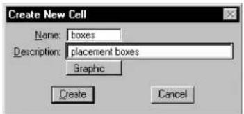
text_image
Create New Cell Name: boxes Description: placement boxes Graphic Create Cancel- In the Name field, key in a name.
- (Optional) — In the Description field, key in a description.
- From the option menu, choose the Cell type (see page 5-7).
- Click the Create button.

Alternatively, you can define the cell origin (steps 4–5) before selecting or fencing the elements (step 3) to be included in the cell.

One or more cells can be made part of another cell, or nested. Just select the cells to be nested when you create the new cell. If a cell with the same name as the nested cell exists in the library, the nested cell is replaced by a reference to the cell in the cell library. When the cell is placed, the reference is expanded back to the original geometry.

To edit the name or description of a cell
- From the Element menu, choose Cells.
The Cell Library dialog box opens. - In the list box, select the name of the desired cell.
- In the lower right corner of the Cell Library dialog box, click the Edit button.

The Edit Cell Information dialog box opens.
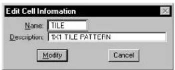
text_image
Edit Cell Information Name: TILE Description: 1X1 TILE PATTERN Modify Cancel- Edit the name, description, or both.
- Click the Modify button.
▶ Todeleteacellfromtheattachedcelllibrary
- From the Element menu, choose Cells.
The Cell Library dialog box opens.
-
In the list box, select the name of the desired cell.
-
In the lower right corner of the Cell Library dialog box, click the Delete button.
Since the deletion cannot be undone, an alert box opens, asking you to confirm that you want to delete the selected cell. ^1
- Click OK.
ByCell
When a cell is created, the symbology (i.e., color, line style and line weight) of each element is established. When that cell is placed in a DWG file, this symbology is used. However, it is possible to leave the symbology open ended by using ByCell. If By Cell is selected as the color, line style and/or line weight, when the cell is placed the active attributes are used. For example, if a cell is created containing a square with color set to red and a circle with color set to ByLevel, when the cell is placed into a DWG file with color set to yellow, the square appears in red and the circle appears in the active color of yellow.

ByCell is only enabled, by default, on DWG workmode. You can enable ByCell in DGN workmode by adding _USTN_CAPABILITY > -CAPABILITY_NO-BYCELL to the standards.cfg configuration file.
Placing Cells
Before you can place a cell, you must activate it for the desired method of placement:

• For general Placement with the Place Active Cell tool (see page 5-15) or the Place Active Cell Matrix tool (see page 5-18) in the Cells tool box (see page 5-14). This cell is called the Active Cell.


- As a line Terminator with the Place Active Line Terminator tool (see page 5-23) in the Cells tool box. This cell is called the Active Line Terminator.
• As a Point cell, for placement with the tools in the Points tool box (see page 2-54). This cell is called the Active Point Cell.
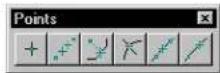

- For Patterning with the Pattern Area tool (see page 5-52) in the Patterns tool box. This cell is called the Active Pattern Cell.
To designate a cell as an active cell
- From the Element menu, choose Cells.
The Cell Library dialog box opens. - In the list box, select the name of the cell.
- Click the button — Placement, Terminator, Point, or Pattern — in the Active Cells section.
Alternative method — To designate a cell as an active cell
- From the Utilities menu, choose Cell Selector.
The Cell Selector dialog box opens. Each cell in the attached cell library is displayed on its own button.
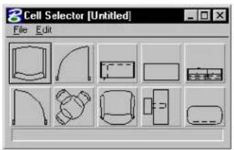
text_image
3 Cell Selector [Untitled] File Edit- Click the button on which the cell you want to make active is displayed.
Not only is the cell activated, but the pre-designated cell placement tool for that cell is automatically selected as well.

You can customize the Cell Selector dialog box for other uses.
Controlling the level on which cells are placed
The Relative tool setting for the Place Active Cell tool and Select and Place Cell tool (see page 5-20) controls the level(s) on which a graphic cell is placed.
- If Relative is off, a graphic cell is placed on the same level(s) as it was created (absolute placement).
- If Relative is on, a graphic cell is placed on a level or levels relative to the Active Level. For example, consider a graphic cell that was created with elements on levels 5, 7, and 8. If Relative is on and the Active Level is 1, the cell is placed on levels 1, 3, and 4. If the Active Level is 45, the cell is placed on levels 45, 47, and 48.

For information about what it means for a cell to be a “graphic cell,” see “Cell types” on page 5-7.
Shared cells
If Use Shared Cells is on in the Cell Library dialog box, cells are placed as shared cells.
What is a shared cell?
The first time you place a cell with Use Shared Cells on, the shared cell definition (elements comprising the cell) is stored in the DGN file in much the same way as it is stored in the cell library. To place subsequent instances of the shared cell, the cell library does not need to be attached. In other words, a shared cell can have many instances in a DGN but only one definition. When a shared cell instance is replaced using the Replace Cells tool (see page 5-25), all instances of the cell are replaced!
For an unshared cell, on the other hand, the library definition is stored in the DGN file each time the cell is placed. Using shared cells can therefore be a way to reduce DGN file size. The reduction is greatest in files with cells that have a large number of component elements and/or instances.

It is not necessary to know where the shared cell definition is in the DGN file; identifying any instance of the shared cell identifies the actual definition.
Reasons to use shared cells
The use of shared cells is recommended for these reasons:
- Shared cells are faster to place and manipulate than unshared cells. The first time a cell is placed in the DGN file, the cell library in which it is stored must be attached. If the cell is placed as a shared cell, it is not necessary to have the cell library attached to place additional instances of that cell.
- All instances of a shared cell in the DGN file are replaced when any instance of that shared cell is replaced.
- Shared cells can be associated with points on other elements, if Association Lock (Settings >Locks >Association) is on. For example, if a shared door cell is placed in a wall and associated with that wall, the door will automatically move if the wall is moved.
- Shared cells usually reduce DGN file size, thereby improving performance.
Cells tool box
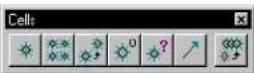
The tools in the Cells tool box are used to place and manipulate cells.
| To | Select in the Cells tool box |
| Place the active cell. |  Place Active Cell (see page 5-15) Place Active Cell (see page 5-15) |
| Place a matrix (rows and columns) of the active cell. |  Place Active Cell Matrix (see page 5-18) Place Active Cell Matrix (see page 5-18) |
| Identify a cell and place an additional instance(s). |  Select and Place Cell (see page 5-20) Select and Place Cell (see page 5-20) |
| Define the cell origin (the point about which the cell is placed) when creating the cell. |  Define Cell Origin (see page 5-22) Define Cell Origin (see page 5-22) |
| Display the name and level of a cell that is in the DGN file. |  Identify Cell (see page 5-23) Identify Cell (see page 5-23) |
| Add a terminator to a line segment. |  Place Active Line Terminator (page 5-23) Place Active Line Terminator (page 5-23) |
| Replace a cell(s) (or all instances of a shared cell) in the design with another of the same name from an attached library. |  Replace Cells (see page 5-25) Replace Cells (see page 5-25) |
Key-in: DIALOG TOOLBOX CELLS [OFF | ON | TOGGLE]

To select and place cells by clicking thumbnail representations, use the Cell Selector dialog box (Utilities menu > Cell Selector).

You can define Cell settings group components that, when selected, automatically adjust the active scale factors for cell placement.

To convert an instance of a shared cell to an unshared cell, use the Drop Element tool (see page 7-10) in the Groups tool box.
Place Active Cell

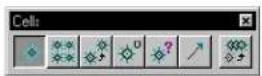
Used to place the Active Cell.
The Active Level is set in the Primary Tools tool box.
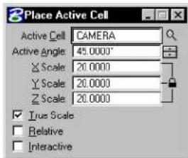
text_image
Place Active Cell Active Cell CAMERA Active Angle 45.0000° X Scale 20.0000 Y Scale 20.0000 Z Scale 20.0000 True Scale Relative Interactive| Tool Setting | Effect |
| Active Cell | Can be keyed-in here or set in the Cell Library dialog box (Element menu > Cells). See “Cells” in the Reference Guide for more information on the Cell library dialog box. |
| Browse Cells | Opens the Cell Libraries dialog box for purposes of placement of a different active cell. |
| Active Angle | Sets the angle by which the cell is rotated, if Interactive is off. |
| X Scale | Horizontal scale factor (along x-axis)1 |
| Y Scale | Vertical scale factor (along y-axis)1 |
| Z Scale | De pth scale factor (along z-axis)1 |
1 Direction in the cell definition. If a scale factor is between 0–1 (for example, 0.25), the size is decreased. If a scale factor is 1, the size is unchanged from the cell definition. If a scale factor is greater than 1, the size is increased.
| Tool Setting | Effect |
| Relative | If the active cell is a graphic cell ^1 and Relative is:On—lowest level in cell is placed on the Active Level, and higher levels in cell are placed relative to the Active Level. ^2 Off—cell is placed on same level(s) as in cell library (the level(s) that components were on when the cell was created). |
| Interactive | If on, the scale and rotation angle are defined graphically by data points. |
1 Point cells are always placed on the Active Level.
2 For example, consider a graphic cell that was created with elements on levels 5, 7, and 8. If Relative is on and the Active Level is 1, the cell is placed on levels 1, 3, and 4. If the Active Level is 45, the cell is placed on levels 45, 47, and 48.
To place the Active Cell
- Select the Place Active Cell tool.
- Enter a data point to position the cell origin. If Interactive is off, the cell is placed.
- If fI Interactive isom, enter two more data points to define the scale and the notation angle.
- Reset to finish. or Return to step 2 to place another instance of the cell.
Place Active Cell. Left: At Active Angle and scale (Interactive off). Right: Defining rotation and scale with data points (Interactive on).
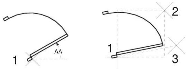
text_image
1 AA 2 1 3Key-in: PLACE CELL ICON
Key-in: PLACE CELL INTERACTIVE [ABSOLUTE | RELATIVE]

The ACTIVE CELL (AC=) and ACTIVE RCELL (AR=) key-ins can be used to set a cell (a shared cell or a cell in the attached cell library) as the active cell and place it in the DGN file.
| Key-in Like Place Active Cell with | |
| AC== | Relative Off |
| AR== | Relative On |
1 cell_name is the name of a shared cell in the file or a cell in the attached cell library or cell library list.
For example, to set CELL1 as the active cell and place it with its lowest level on the Active Level, key in AR=CELL1.
Place Active Cell Matrix

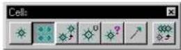
Used to place a matrix of the Active Cell. The cells are placed at the Active Angle and Active Scale on the same level(s) as in the cell definition, unless it is a point cell. Point cell components are placed on the Active Level.
The Active Angle and Active Scale can be set in the DGN File Settings dialog box (Settings menu > Design File...). The Active Level is set in the Attributes tool box.
See "DGN File Settings dialog box" in the online Reference Guide for more information on the DGN File Settings dialog box.
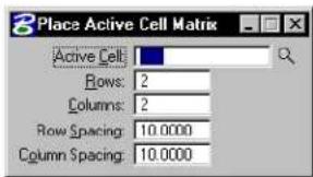
text_image
Place Active Cell Matrix Active Cell: Rows: 2 Columns: 2 Row Spacing: 10.0000 Column Spacing: 10.0000| Tool Setting | Effect |
| Active Cell | Sets the Active Cell, which can be keyed-in here or set by clicking the Placement button in the Cell Library dialog box (Element menu > Cells). See “Cells” in the Reference Guide for more information on Cells. |
| Browse Cells | Opens the Cell Libraries dialog box for purposes of placement of a different active cell. |
| Rows | Sets the number of rows. |
| Columns | Sets the number of columns. |
| Row Spacing | Sets the space, in working units, between rows. |
| Column Spacing | Sets the space, in working units, between columns. |
To place a matrix of the Active Cell
- Select the Place Active Cell Matrix tool.
- Enter a data point to position the cell matrix. The origin of the cell in the lower left corner of the matrix is placed at this point.
Place Active Cell Matrix. D1 indicates the row spacing. D2 indicates the column spacing.
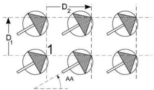
text_image
D₁ D₂ 1 AAKey-in: MATRIX CELL
Key-in: CM=〈rows, columns, row_spacing, column_spacing〉
Select and Place Cell

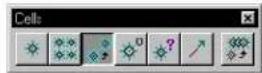
Used to identify a cell in the DGN file and place an additional instance(s) of that cell. The Active Level is set in the Attributes tool box.
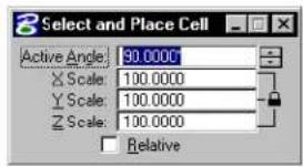
text_image
Select and Place Cell Active Angle: 90.0000 X Scale: 100.0000 Y Scale: 100.0000 Z Scale: 100.0000 Relative| Tool Setting | Effect |
| Active Angle | Sets the angle by which the cell is rotated. |
| X Scale | Sets horizontal scale factor (along x-axis). ^1 |
| Y Sα a l e | Sets vertical scale factor (along y-axis). ^1 |
| Z S α a l e | In 3D, sets scale factor along z-axis. ^1 |
1 Direction in the cell definition. If a scale factor is between 0-1 (for example, 0.25), size is decreased; if it is 1, size is unchanged from the cell definition; if it is greater than 1, size is increased.
| Tool Setting | Effect |
| Relative | If Active Cell is a graphic cell and Relative is: ^1 On—the lowest level in the cell is placed on the Active Level, and higher levels in the cell are placed relative to the Active Level. ^2 Off—the cell is placed on the same level(s) as in the cell library (the level(s) that the components were on when the cell was created). |
1 Point cells are always placed on the Active Level.
2 For example, consider a graphic cell that was created with elements on levels 5, 7, and 8. If Relative is on and the Active Level is 1, the cell is placed on levels 1, 3, and 4. If the Active Level is 45, the cell is placed on levels 45, 47, and 48.
To select and place cell cell
- Select the Select and Place Cellbootool.
- Identify the cell.
If the cell is shared and Use Shared Cellision it becomes the Active Cell.
If the cell is unshared, the cell library in which that cell is stored must be attached or in the cell library list.
- Enter a data point to place an instance of the cell.
- Reset to finish.
or Return to step 3 to place another instance of the cell.
Key-in: SELECT CELL ICON
Key-in: SELECT CELL [ABSOLUTE | RELATIVE]
Define Cell Origin

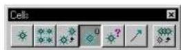
Used to define the cell origin (the point about which the cell is placed). See "To create a cell" on page 5-8 for information about creating cells.
To define a cell origin
- Select the Define Cell Origin tool.
- Enter a data point to define the cell origin.
A “+” displays at this point.
The origin stays active and displays until the next time the Define Cell Origin tool is selected.
- Reset to accept the cell origin. or Return to step 2.
Key-in: DEFINE CELL ORIGIN
√ It is often helpful to snap a tentative point to preview the data point to be entered in step 2.
Identify Cell

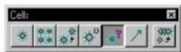
Used to display the name and level of a cell in the design.
To display a cell's name and level
- Select the Identify Cell tool.
- Identify the cell.
The cell's name and level(s) are displayed in the status bar.
- Accept the cell.
Key-in: IDENTIFY CELL
Place Active Line Terminator

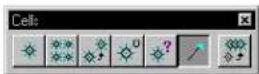
Used to place the Active Line Terminator cell on a line, line string, or arc, primarily to place arrowheads.
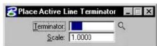
| Tool Setting | Effect Alternate key-in | |
| TerminatorSets Active LineTerminator, whichcan als o bes et in tCell Library dialog box(Element menu > Cells). | ACTIVETERMINATOR<TERMINATOR>orLT= | |
| Browse Cells Opens the Cell Librariesdialog box for purposesof selecting a differentactive cell as a lineterminator. | ||
| Scale | Sets Active LineTerminator scale. | ACTIVE=TSCALE |
| orTS= | ||
To place the Active Line Terminator
- Select the Place Active Line Terminator tool.
- Identify the element near the endpoint where the terminator is to be placed.
- Accept the line terminator.
Place Active Line Terminator
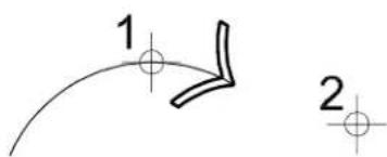
text_image
1 2Key-in: PLACE TERMINATOR
√ To place text (a note) in the DGN file with an arrow, it is easiest to use
the Place Note tool in the Text tool boxTools menu > Main > Text).
Replace Cells

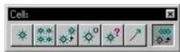
Used to replace single or multiple cells in a DGN file, or to update cells in a DGN file with cells of the same name from the active cell library.
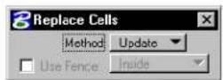
| Tool Setting | Effect |
| Method | Sets the method for replacing or updating cells.Update—replaces the identified cell with the cell of the same name from the active cell library.Replace—replaces single or multiple cells by identifying the cell and then identifying its replacement cell. |
| Mode (with | Method set to Replace) Sets the method by which cells are replaced.Single—lets you replace individual cells.Global—replaces all cells of the same name with the replacement cell. |
| Use Active Cell | (with Method set to Replace) If on, selected cells are replaced with the Active Cell entered in the text field. |
| Browse Cells | Opens the Cell Libraries dialog box for purposes of placement of a different active cell. |
| Replace Attributes | (with Method set to Replace) If on, all user data (such as tags and database attributes) associated with a cell are replaced by the new cell's user data. |
| Use Fence | Sets the method by which fence contents are manipulated.Inside-if Mode is set to Single, all cells inside the fence are replaced. If Mode is set to Global, all cells inside the fence, as well as cells outside the fence having the same name as those inside the fence, are replaced.Overlap-if Mode is set to Single, all cells inside and overlapping the fence are replaced. If Mode is set to Global, all cells inside and overlapping the fence, as well as cells outside the fence having the same name as those inside and overlapping the fence, are replaced.Vo i d -if Mode is set to Single, all cells outside the fence are replaced. If Mode is set to Global, all cells outside the fence, as well as cells inside the fence having the same name as those outside the fence, are replaced.Void-Overlap-if Mode is set to Single, all cells outside and overlapping the fence are replaced. If Mode is set to Global, all cells outside and overlapping the fence, as well as cells inside the fence having the same name as those outside and overlapping the fence, are replaced. |
To update cells from the active cell library
- Select the Replace Cells tool.
- In the Tool Settings window, set Method to Update.
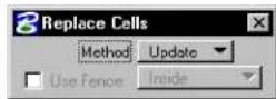
-
Identify the cell to update.
-
Accept the cell.
If the identified cell is shared, all instances of the cell in the design are replaced with the cell of the same name from the active cell library.
If the identified cell is unshared, only the identified cell is replaced with the cell of the same name from the active cell library.
To replace cells individually or globally
- Select the Replace Cells tool.
- In the Tool Settings window, set Method to Replace.
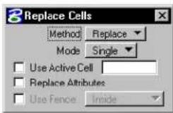
-
Identify the cell to replace.
-
Identify the replacement cell.
-
Accept.
If Mode is set to Single, the identified cell is replaced.
If Mode is set to Global, an alert box opens to confirm the replacement of all of the cells having the same name as the identified cell.
To replace individual or multiple cells inside the fence
- Place the fence around the cells to replace.
- Select the Replace Cells tool.
- In the Tool Settings window, set Method to Replace.
- In the Tool Settings window, turn on Use Fence and choose the Inside option.
- Identify the replacement cell.
- Accept.
If Mode is set to Single, all of the cells inside the fence are replaced.
If Mode is set to Global, all of the cells inside the fence and those cells outside the fence having the same name are replaced in groups; after you click Yes in the alert box to confirm the replacement of one group of cells, subsequent alert boxes appear until all of the cells in the fence and those cells of the same name outside of the fence are replaced.
To individually replace cells containing user data
- Select the Replace Cells tool.
- In the Tool Settings window, set Method to Replace.
- In the Tool Settings window, set Mode to Single.
- In the Tool Settings window, turn on Replace Attributes.
- Identify the cell to replace.
- Identify the replacement cell.
- Accept.
The old cell, including its user data, is replaced with the new cell and its user data.
Key-in: REPLACE CELLS EXTENDED
To replace cells from the system command line, enter at the system prompt: msbatch repcell.ma
DGN file is the DGN file on which to operate, cell_library is the cell library that contains the replacement cell, y keeps attributes, n does not keep attributes, cell_to_replace is the name of the cell in design_file to replace, and replacement_cell is the name of the replacement cell in cell_library.

You many experience a limit to the number of files that can be included in one batch when using MSBATCH. This limit is related to the amount of system resources available and will vary from system to system. Typically, the more physical memory and swap space available, the more files you can include in a single batch process.

The Replace Cells tool cannot be used to replace groups (unnamed cells, also known as “orphan cells”).
Hatching and Patterning
Patterning is the repeated placement of a hatch line or cell through a closed area at a specified interval (spacing), scale, and angle. You can place patterns on any designated level.

When using a hatching or patterning tool with the tool setting Method set to Flood, Union, Intersection, or Difference, turning on Dynamic Area along with Associative Pattern lets you create patterns that regenerate themselves when their bounding elements are modified. As well, you can create single associative patterns with disjoint regions.

In DWG workmode, by default, area patterning is replaced by AutoCAD pre-defined hatching. The Pattern field in the Pattern Area (see page 5-52) settings window is a combo box which, by default, lists the patterns in the DWG pattern file "areapat.pat". This file contains a DWG pattern definition for each pattern cell in the supplied cell library, "areapat.cel".
To select a different DWG pattern file, key in its full file specification — path and filename — in Pattern File or click the adjacent magnifying glass icon to browse the file system.
A corresponding DWG pattern file is supplied for each of the important, supplied pattern cell libraries — "archpat.cel", "areapat.cel", "geompa.cel", "igespats.cel", "linepa.cell", and "utilpat.cel". These DWG pattern files have the same filename as their cell library counterparts except their extension is .pat.
Controlling the display of patterns
Elements — either lines or cells — in a pattern are designated as pattern elements.
To turn the display of patterns on or off in one or more views
- From the Settings menu, choose View Attributes. The View Attributes dialog box opens.
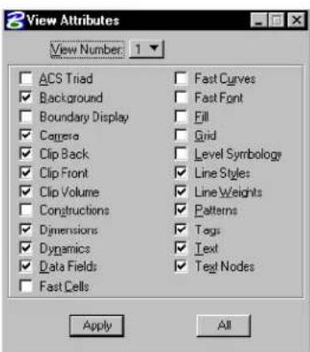
text_image
View Attributes View Number: 1 ACS Triad Background Boundary Display Cages Clip Back Clip Front Clip Volume Constructions Dimensions Dynamics Data Fields Fast Cells Fast Curves Fast Font Fill Grid Level Symbology Line Styles Line Weights Patterns Tags Text Text Nodes Apply All- From the View Number option menu, choose the number of the desired view.
- Turn Patterns on or off.
- Click the Apply button.
- Repeat steps 2–4 for additional views.
To turn the display of patterns on or off in all views
- From the Settings menu, choose View Attributes.
The View Attributes dialog box opens.
-
Turn Patterns on or off.
-
Click the All button.
Placing patterns in the design
The tools in the Patterns tool box (see page 5-39) are used to pattern the area inside a closed element with the Area attribute of Solid, the fence, the intersection, union, or difference of multiple elements, or the area enclosed by a set of elements. Elements used to create the patterned area can be in either the active file, one or more references, or a combination of both.


The Hatch Area tool (see page 5-40) and Crosshatch Area tool (see page 5-49) are used to place lines (hatch lines).
Hatching (left) and Crosshatching (right).
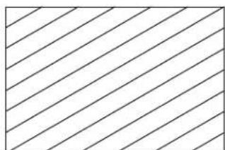
natural_image
Pure diagonal line pattern with no text, numbers, or symbols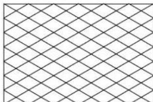
natural_image
Pure geometric pattern of intersecting diagonal lines forming diamond shapes (no text or symbols)The Pattern Area tool (see page 5-52) is used to place the cell designated as the Active Pattern Cell. For example, a wall face can be patterned with a brick cell for a more realistic appearance.

Examples of placing the Active Pattern Cell.

Area patterning can be a time-consuming operation, depending on the complexity of the Active Pattern Cell and the size of the patterned area. The time also depends on the number, intricacy, and levels of hole elements within the area. More intricate elements may require several minutes to pattern.
Associative patterns
Turning on Associative Pattern, when you use the Hatch Area tool (see page 5-40), Crosshatch Area tool (see page 5-49), or Pattern Area tool (see page 5-52), causes the pattern to be associated with the patterned element. This means that whenever the element is modified or manipulated, the pattern automatically is updated.
If an element that has an associated pattern is rotated or scaled, the associated pattern also is rotated or scaled.
Associative patterns can be created from:
• elements in the active DGN file
- elements in references, including nested reference and self-references
• a combination of elements from the active file and references
When any of the elements used to create the patterned area are modified, whether they be from the active file or a reference, the associated patterning updates also.
natural_image
Simple geometric shape with diagonal hatching and a U-shaped cutout (no text or symbols)
natural_image
Pure geometric shape with hatched fill, no text or symbols presentHatching the shape on the left, with Associative Pattern turned on, means that if you modify it later (right), the hatching updates automatically to the new shape.
Snappable patterns
Turning on Snappable Pattern, when you use the Hatch Area tool (see page 5-40), Crosshatch Area tool (see page 5-49), and Pattern Area tool (see page 5-52), causes the pattern element to be eligible for snapping.
While, in some cases, being able to snap to pattern elements is desirable, in others it is not, since having large numbers of pattern elements in an area may make it difficult to select or identify a particular element.
Excluding areas inside a patterned area from patterning
When you create a shape, circle, or ellipse, defining an area for patterning, you can exclude patterning in regions within this element. You do this by placing other shapes, circles, or ellipses within the outer element. Additionally, you can exclude the areas surrounding text in the patterned region. You have several ways to define the areas for patterning, and those to be excluded.
Setting elements to be Solid or Hole
When you create shapes, circles, or ellipses, you have the choice of setting their Area to be Hole or Solid. This can affect the way that elements are hatched or patterned. Usually, the areas enclosed by "hole" elements, located inside and on the same level as the Solid element, are not patterned. This applies as follows:
| Associative Pattern | Hole Elements Inside Element |
| Off Are not patterned. | |
| On If they were g | rouped with the solid element using the Group Holes (see page 7-25) tool — they are not patterned.If they were not grouped with the solid element — they are ignored and the selected solid element is patterned with no “holes”. |
Using tool settings
Tool settings for the Hatch Area, Crosshatch Area, and Pattern Area tools, let you exclude areas in closed elements from being patterned. With each of these tools, Method can be set to:
- Intersection — patterned region is where two or more selected elements intersect.
- Difference — lets you select a main element to pattern from which other selected elements are subtracted.
- Flood — lets you pattern the interior of bounding elements. Additionally, you can specify that interior shapes and/or text are not to be patterned or that alternating areas are patterned where shapes are nested inside one another.
Using Alternating Area to exclude nested areas from patterning
When you have areas nested inside others, you can pattern alternate
regions in one step using the Flood method with both Locate Interior Shapes and Alternating Area turned on. In the example below, the hatching was performed in a single operation.
natural_image
Simple diagram with two circles inside a rectangle, no text or symbols present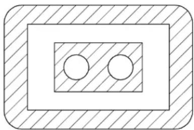
natural_image
Simple geometric diagram with two circles inside a rectangle, no text or symbols presentThe Alternating Area setting, in conjunction with Locate Interior Shapes, lets you flood hatch/pattern the nested areas (left) to produce the required result (right) in one step.
Manipulating/modifying excluded regions
When you pattern an area, with Associative Pattern turned on, you can manipulate or modify the elements defining the regions and the pattern will update accordingly to conform to the modified regions.
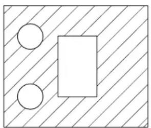
natural_image
Simple geometric diagram with a rectangle, two circles, and diagonal hatching (no text or symbols)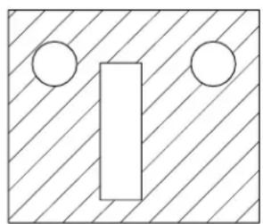
natural_image
Simple geometric diagram with diagonal hatching and two circles around a vertical rectangle (no text or symbols)When you manipulate or modify a shape, or excluded area, that has been hatched/patterned with Associative Pattern turned on (left), the patterning updates accordingly (right).
Patterning disjointed regions
With Method set to Flood, and Dynamic Area turned on, you can pattern disjointed elements. That is, by holding down the
Left: Select the regions to "flood" hatch (
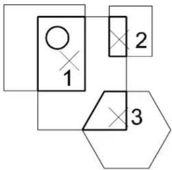
flowchart
graph TD
    A["Input"] --> B["Process Step 1"]
    B --> C["Output"]
    D["Processing Step 2"] --> B
    E["Output"] --> F["Process Step 3"]
natural_image
Geometric diagram with squares, circles, and hexagons, no text or symbols present
A single associative pattern region can consist of many disjointed sub-regions. A sub-region may be the smallest area enclosed by many elements or simply the area of a closed shape. A sub-region can contain grouped holes and text elements.
Cells used for patterning
Pattern cells may contain any combination of elements, even text. Cells used for area patterning typically are designed specifically for that purpose.
Pattern cells supplied with MicroStation
The cell libraries "archpa.cel" and "geompa.cel," in Bentley's
"Workspace\system\cell" directory, contain pattern cells that are useful for various area patterning applications.
 cmbond cmbond |  flbond flbond |  flcomm flcomm |  enbond enbond |  crsrl crsrl |  ranrbl ranrbl |  porous porous |
 shngle shngle |  brick brick |  sbrick sbrick |  vbrick vbrick |  stucco stucco | 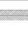 hrngfl hrngfl |  rock2 rock2 |
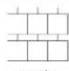 coasn coasn | 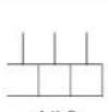 cdik8 cdik8 | 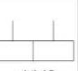 cdik16 cdik16 |  rblock rblock |  gblock gblock |  grade2 grade2 |  |
 wood2 wood2 |  wood3 wood3 |  concr2 concr2 |  |  hbone hbone |  honey honey |  gravel gravel |
Examples of cells in "archpa.cel" cell library.
 geom1 geom1 | [0W65]geom2 | [03AD]geom3 |  geom4 geom4 |  geom5 geom5 |  geom6 geom6 |  geom7 geom7 | [7BA7]geom8 | [7TZZ]geom9 |  geom10 geom10 |
 geom11 geom11 | [0YWD]geom12 |  geom13 geom13 | [AZZX]geom14 | [4X0A]geom15 |  geom16 geom16 | [3XX4]geom17 |  geom18 geom18 | [DAAO]geom19 |  geom20 geom20 |
 geom21 geom21 | [20WC]geom22 | [0WWC]geom23 | [Y06K]geom24 |  geom25 geom25 |  geom26 geom26 |  geom27 geom27 |  geom28 geom28 |  geom29 geom29 |  geom30 geom30 |
 geom31 geom31 |  geom32 geom32 |  geom33 geom33 | [70WK]geom34 |  geom35 geom35 | [576W]geom36 |  geom37 geom37 |  geom38 geom38 |  geom39 geom39 |  geom40 geom40 |
| [0H4X]geom41 | [20ZD] | [H8ZA] |  |  |  |  |
Examples of cells in "geompa.cel" cell library.
Guidelines for creating pattern cells
Additional pattern cells are created just as all other cells are. Here are some guidelines to follow and restrictions to be aware of when creating area pattern cells:
• Area pattern cells should contain at least one full cycle of the pattern in both the horizontal and vertical directions.
- The cell range is used to determine the pattern matrix size. If you want unused space at the pattern boundary, place point elements (zero length lines) to expand the pattern range. Point elements are not patterned.
- If the cell is created as a point cell, the pattern components are placed on the Active Level in the active color and line weight. If the cell is created as a graphic cell, the pattern elements are placed with the same symbology and on the same level as the element being patterned.
- The Pattern Area tool (see page 5-52) handles horizontal or vertical lines that span the entire pattern cell in a special manner. Instead of placing many contiguous line segments to create the pattern, these lines are extended through the entire pattern area. This results in a substantial increase in patterning speed and also requires much less room in the DGN file.
Tolerance
When patterning along or inside a curved element, the curve is approximated with a series of line segments that are used as "guides."
The tool setting Tolerance is the maximum distance in working units between a curved element and the approximating line segments used to pattern. If the Tolerance is small, the line segments conform closely to the curve and the approximation is more accurate, but processing time increases. If the Tolerance is large, line segments do not conform as closely to the curve and the approximation is less accurate, but processing time decreases. The setting can be saved.
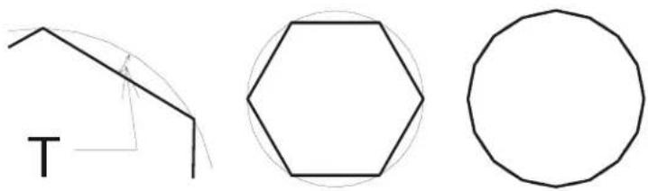
natural_image
Three simple geometric shapes: a triangle, a hexagon, and a circle, drawn with black lines on white background (no text or symbols)Left: Tolerance as denoted by "T". Center: Approximating line segments if tolerance is large. Right: Approximating line segments if tolerance is small.
Patterns tool box
The tools in the Patterns tool box are used to pattern areas and along linear elements.
| To | Select in the Patterns tool box |
| Hatch an area. |  Hatch Area (see page 5-40) Hatch Area (see page 5-40) |
| Crosshatch an area. |  Crosshatch Area (see page 5-49) Crosshatch Area (see page 5-49) |
| Patternanareatiling the Active Pattern Cell. |  Pattern Area (see page 5-52) Pattern Area (see page 5-52) |
| Pattern along a linear element. |  Linear Pattern (see page 5-59) Linear Pattern (see page 5-59) |
| Display the angle and scale attributes of a pattern element. |  Show Pattern Attributes (see page 5-62) Show Pattern Attributes (see page 5-62) |
| Set the active pattern settings to match the attributes of an existing pattern element. |  Match Pattern Attributes (see page 5-63) Match Pattern Attributes (see page 5-63) |
| Delete patterning. |  Delete Pattern(see page 5-64) Delete Pattern(see page 5-64) |
Key-in: DIALOG TOOLBOX PATTERNS[OFF | ON | TOGGLE]
Hatch Area

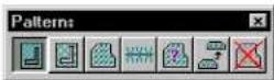
Used to hatch an area. Elements used to define the area to be hatched can be in the active model, or in references. Where associative patterning is used, any modification to elements defining the hatched area results in an equivalent update to the hatching.
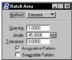
text_image
3 Hatch Area Method: Element Spacing: 1.0000 Angle: 45.0000 Tolerance: 0.0000 ✓ Associative Pattern □ Snappable Pattern| Tool Setting | Effect |
| Method | Determines the area that is hatched. Element—The interior of a shape, ellipse, or closed B-spline curve;1or between components of a multi-line.Fence—The area inside the fence.Intersection—Of two or more closed elements.1Union—Of two or more closed elements.1Difference—Between two or more closed elements.1Flood—The (minimum) area enclosed by a set of elements (something like the flood fill tool common in painting programs). With method set to Flood, a Show Extended Information icon appears in the lower right corner of the tool settings window. Clicking this icon expands the tool settings to display further controls.Points—An area defined by a series of data points, each of which defines a vertex. |
| Spacing | Sets the interval between hatching lines. |
| Angle | Sets the angle at which hatching lines are drawn. By default, the angle is relative to the view being used. Where AccuDraw is active, however, the angle is relative to the AccuDraw drawing plane. |
| To le r an (see page 5-38) | c dMaximum distance between curved element and approximating line segments used to pattern. |
| Associative Pattern | If on, hatching is associated with the patterned element and is automatically updated when the element is manipulated or modified. In other words, if the element is modified later, the hatch lines are re-drawn to match the modified element.If Method is Intersection, Union, Difference, or Flood, a complex shape that bounds the patterned area is created, and the hatch lines are associated to the complex shape. If you move or modify the original element(s), used to create the complex shape, the complex shape is updated, along with the hatching. ^2 |
| Snap-pable Pattern | If on, hatching lines can be snapped to. If off, hatching lines do not interfere with snapping to other elements. |
| Locate Interior Shapes | (Method set to Flood only) If on, all closed elements (regardless of their Area attributes) inside the selected area are avoided when the area is hatched. |
| Locate Te x t | (Method set to Flood only) If on, any text or dimension text inside or overlapping the selected area is avoided when the area is hatched. |
| Dynamic Area | (Method set to Flood only) If on, the area to be hatched displays dynamically as you move the screen pointer over the shapes. |
| Alternating Area | (Method set to Flood only, with Locate Interior Shapes on and Dynamic Area off) If on, alternating areas are hatched where shapes are nested inside one another. |
| Max-(imum) Gap | (Method set to Flood only) The maximum distance, in working units, between the endpoints of enclosing elements. |
To be patterned, a closed element's Area attribute must be Solid. An element's Area attribute is changed with the Change Element to Active Area tool in the Change Attributes tool box.
2 To convert associative hatching into line elements that are no longer associated with the element, use the Drop Associative Pattern tool in the Drop tool box.
To hatch the area inside a closed element
- Select the element.
- Select the Hatch Area tool.
- Set Method to Element.
- Enter a data point to define a point through which a hatch line must pass.
Elements that are inside the selected element and have the Area attribute Hole are hatched as follows:
| If Associative Pattern is | Then Hole elements inside selected element |
| Off Are not hatched. | |
| On If they were gr | ouped with the Solid element using the Group Holes tool (see page 7-25), they are not hatched and the hatching is associated with the Hole elements as well as the Solid.Otherwise, the area enclosed by any other element inside the element, regardless of its Area attribute, is hatched, and no associations are made to it. |
Alternative method — To hatch the area inside a closed element
- Select the Hatch Area tool.
- Set Method to Element.
- Identify the element.
- Enter a data point to define a point through which a hatch line must pass.
Hatching the area inside a closed element. Identify the element (1) and then enter a data point to define a point through which a hatch line must pass. "A" denotes the Active Pattern Angle. "S" denotes the Active Pattern Spacing.
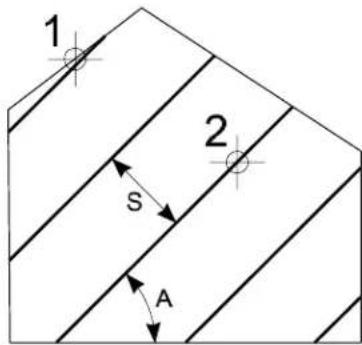
text_image
1 2 S ATo hatch the area between multi-line components
-
Select the Hatch Area tool.
-
Set Method to Element.
-
Identify one component that is to be a boundary of the hatched area.
-
Identify the other component that is to be a boundary of the hatched area.
If Associative Pattern is off, this data point defines a point through which one of the hatch lines must pass.
- Reset.
Hatching the area between multi-line components.
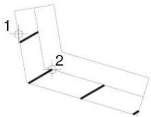
natural_image
Pure geometric diagram of a 3D L-shaped structure with labeled points 1 and 2 (no text or symbols beyond labels)5-44 MicroStation User Guide
To hatch the fenced area
- With the fence present, select the Hatch Area tool.
- Set Method to Fence.
- Enter a data point to define a point through which a hatch line must pass.
To hatch the intersection or union of closed elements
- Select the Hatch Area tool.
- In the Tool Settings window, set Method to Intersection or Union.
- Identify one element.
- Identify another element(s).
As you accept each successive element, the edges that do not enclose the area to be hatched are hidden. The resulting area is highlighted.
If the elements do not overlap, the following occurs, depending on the Method:
| Method If elements | do not overlap, then |
| Intersection | “Elements do not intersect” is displayed in the status bar. |
| Union | All elements are hatched. |
- After you accept the last element, Reset to finish (or select a different tool).
The area is hatched. The final acceptance point defines a
point through which a hatch line must pass.
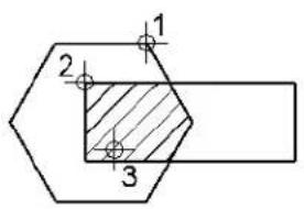
text_image
1 2 3
text_image
1 2 3Identify one element (1) then another element (2), accept (3), then Reset to finish. Results with Method set to Intersection (left) and Union (right).
To hatch the difference between elements
- Select the Hatch Area tool.
- Set Method to Difference.
If any elements are selected, they are de-selected. - Identify the element from which to subtract.
- Identify the element(s) to subtract from the element that was identified in step 3.
- Accept the elements.
The area to be hatched is displayed dynamically. - Reset to finish.
With Method set to Difference, identify the first element (1) and the element to subtract (2), then accept (3).
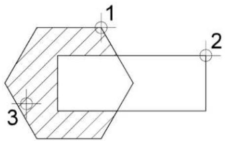
text_image
1 2 35-46 MicroStation User Guide
To hatch an area enclosed by bounding elements
- Select the Hatch Area tool.
- Set Method to Flood.
- (Optional) — If you want the hatching to avoid closed elements, text or dimension text inside the selected area, or you want to view the hatch area dynamically, click Show Extended Information (lower right in the tool settings) and turn on Locate Interior Shapes, Locate Text, and/or Dynamic Area.
- Enter a data point in the area enclosed by the bounding elements. (To minimize the time required, zoom in to the area of interest or select the bounding elements.)
The area to be patterned is displayed dynamically.
If there are selected elements, only selected elements are considered as possible bounding elements. If no elements are selected, all elements in the view in which the data point is entered are considered.
- Accept the hatching.
The area is hatched. If Locate Interior Shapes and Locate Text is on, any inside closed element (regardless of its Area attribute), text or dimension text is avoided. If Associative Pattern is on, the hatch lines are associated to a complex shape created from the bounding elements and the inside elements.
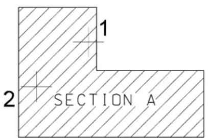
text_image
1 2 SECTION A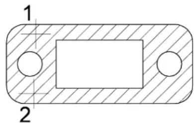
natural_image
Technical drawing of a rectangular mechanical part with two circular holes, shown in cross-section and top view (no text or symbols)Enter a data point inside the bounding elements (1). Accept the hatching (2). Results with Locate Text on (left) and Locate Interior Shapes on (right).
To hatch an area containing nested elements within the bounding elements
- Select the Hatch Area tool.
- Set Method to Flood.
- (Optional) — Click Show Extended Information (lower right in the tool settings) and turn on Locate Interior Shapes, and Alternating Area.
- Enter a data point in the area enclosed by the bounding elements.
The area to be patterned is displayed dynamically. - Accept the hatching.
The areas are hatched alternately. If Associative Pattern is on, the hatch lines are associated to a complex shape created from the bounding elements and the inside elements.
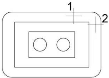
natural_image
Pure geometric diagram with nested rectangles and circles, no text or symbols present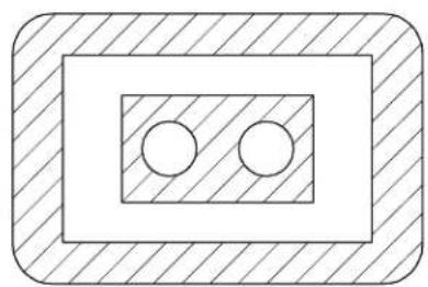
natural_image
Simple diagram with two circles inside a rectangle, enclosed in a hatched border (no text or symbols)Left: Enter a data point inside the bounding elements (1). Accept the hatching (2). Right: With Alternating Area on, alternating enclosed areas are hatched or left blank.
To hatch an area defined by data points
- Select the Hatch Area tool.
- Set Method to Points.
- Enter a data point to define each vertex of an imaginary
shape that encloses the area.
The imaginary shape is dynamically displayed.
- Reset to finish.
Key-in: HATCH [ICON | DIFFERENCE | ELEMENT | FENCE | FLOOD | INTERSECTION | POINTS | UNION]
Crosshatch Area

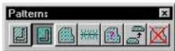
Used to crosshatch an area. Elements used to define the area to be crosshatched can be in the active model, or in references. Where associative patterning is used, any modification to elements defining the crosshatched area results in an equivalent update to the crosshatching.
The tool settings and procedures are the same as those for the Hatch Area tool (see page 5-40), except that there are additional fields to specify the Spacing and Angle of the crosshatch lines, in addition to those for the hatch lines.
Crosshatch
Area. "A1"
and "A2"
denote
the Active
Pattern
Angles.
“S1” and
"S2" denote
the Active
Pattern
Spacing.
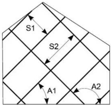
text_image
S1 S2 A1 A2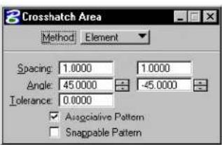
text_image
Crosshatch Area Method Element Spacing 1.0000 1.0000 Angle 45.0000 -45.0000 Tolerance 0.0000 ✓ Associative Pattern □ Snappable Pattern| Tool Setting | Effect |
| Method | Determines the area that is crosshatched. Element—The interior of a shape,ellipse,or closed B-spline curve;1or between components of a multi-line.Fence—The area inside the fence.Intersection—Of two or more closed elements.1Union—Of two or more closed elements.1Difference—Between two or more closed elements.1Flood—The (minimum) area enclosed by a setof elements (something like the flood fill toolcommon in painting programs).Points—An area defined by a series of data points,each of which defines a vertex. |
| Row Spacing | The interval between rows.2 |
| Column Spacing | The interval between columns. |
| Angle | The angle at which instances of the crosshatch areplaced. By default, the angle is relative to the viewbeing used. Where AccuDraw is active, however, theangle is relative to the AccuDraw drawing plane. |
| To le r -ance (see page 5-38) | Maximum distance between a curved element and the approximating line segments used for crosshatching. |
| Associative Pattern | If on, crosshatching is associated with an element and is automatically updated when the element is manipulated or modified. If the Method is Intersection, Union, Difference, or Flood, a complex shape that bounds the crosshatched area is created, and the crosshatching is associated to the complex shape. If you move or modify the original element(s), used to create the complex shape, the complex shape is updated, along with the crosshatching. ^3 |
| Snap-pable Pattern | If on, crosshatched cells can be snapped to. If off, crosshatched cells do not interfere with snapping to other elements. |
| Locate Interior Shapes | (Method set to Flood only) If on, all closed elements (regardless of their Area attributes) inside the selected area are avoided when the area is crosshatched. |
| Locate Te x t | (Method set to Flood only) If on, any text or dimension text inside or overlapping the selected area is avoided when the area is crosshatched. |
| Max-(imum) Gap | (When Method is set to Flood) The maximum distance, in working units, between the endpoints of enclosing elements. |
To be crosshatched, an element's Area attribute must be Solid. An element's Area attribute is changed with the Change Element to Active Area tool in the Change Attributes tool box.
2 If the Row Spacing or Column Spacing is zero, the instances of the Active Pattern Cell are placed contiguous to one another.
3 To convert associative crosshatching into primitive elements that are no longer associated with the element, use the Drop Associative Pattern tool in the Drop tool box.
Key-in: CROSSHATCHICON
Key-in: CROSSHATCH(DIFFERENCE | ELEMENT | FENCE ||
FLOOD | INTERSECTION | POINTS | UNION>

If the second angle is set to zero, Crosshatch Area places the second element at 90^ to the first angle used.
Pattern Area

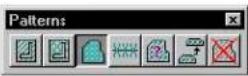
Used to pattern an area by tiling the Active Pattern Cell. Elements used to define the area to be patterned can be in the active file, or in references. Where associative patterning is used, any modification to elements defining the patterned area results in an equivalent update to the patterning.
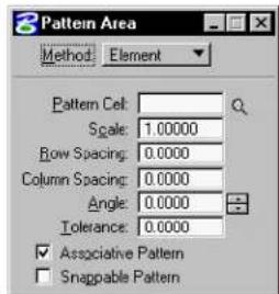
text_image
Pattern Area Method: Element Pattern Cell: Scale: 1.00000 Row Spacing: 0.0000 Column Spacing: 0.0000 Angle: 0.0000 Tolerance: 0.0000 ✓ Associative Pattern ☐ Snappable Pattern| Tool Setting | Effect |
| Method | Determines the area that is patterned. Element—The interior of a shape, ellipse, or closed B-spline curve;1or between components of a multi-line.Fence—The area inside the fence.Intersection—Of two or more closed elements.1Union—Of two or more closed elements.1Difference—Between two or more closed elements.1Flood—The (minimum) area enclosed by a set of elements (something like the flood fill tool common in painting programs).Points—An area defined by a series of data points, each of which defines a vertex. |
| (Active) Pattern Cell | Lets you key in the name of the cell that is tiled to create the pattern. Optionally, you can click the Browse Cells button to the right of the input field, which opens the Cell Library dialog box to let you browse the cells in the attached library, or you can attach a cell library. |
| Browse Cells | Opens the Cell Libraries dialog box for purposes of placement of a different active cell. |
| (Active Pattern) Scale | Sets the factor by which the Active Pattern Cell is scaled.2 |
| Row Spacing | The interval between rows.3 |
| Column Spacing | The interval between columns. |
| (Active Pattern) Angle | The angle at which instances of the active Pattern Cell are placed. By default, the angle is relative to the view being used. Where AccuDraw is active, however, the angle is relative to the AccuDraw drawing plane. |
| To le r - ance (see page 5-38) | Maximum distance between a curved element and the approximating line segments used for patterning. |
| Associative Pat-tern | If on, patterning is associated with a patterned element and is automatically updated when the element is manipulated or modified. If the Method is Intersection, Union, Difference, or Flood, a complex shape that bounds the patterned area is created, and the patterning is associated to the complex shape. If you move or modify the original element(s), used to create the complex shape, the complex shape is updated, along with the patterning. ^4 |
| Snap-pable Pattern | If on, patterning cells can be snapped to. If off, patterning cells do not interfere with snapping to other elements. |
| Locate Interior Shapes | (Method set to Flood only) If on, all closed elements (regardless of their Area attributes) inside the selected area are avoided when the area is patterned. |
| Locate Te x t | (Method set to Flood only) If on, any text or dimension text inside or overlapping the selected area is avoided when the area is patterned. |
To be patterned, an element's Area attribute must be Solid. An element's Area attribute is changed with the Change Element to Active Area tool in the Change Attributes tool box.
2 If between 0–1 (for example, 0.25), size is decreased. If 1, size is unchanged from cell definition. If greater than 1, size is increased.
3 If the Row Spacing or Column Spacing is zero, the instances of the Active Pattern Cell are placed contiguous to one another.
4 To convert associative patterning into primitive elements that are no longer associated with the element, use the Drop Associative Pattern tool in the Drop tool box.
| Tool Setting Effect | |
| Dynamic Area | (Method set to Flood only) If on, the area to be patterned displays dynamically as you move the screen pointer over the shapes. |
| Alternating Area | (Method set to Flood only, with Locate Interior Shapes on and Dynamic Area off) If on, alternating areas are patterned where shapes are nested inside one another. |
| Max(imum) Gap | (When Method is set to Flood) The maximum distance, in working units, between the endpoints of enclosing elements. |
To pattern the area inside a closed element
- Select the element.
- Select the Pattern Area tool.
- Set Method to Element.
- Enter a data point to place the origin of one of the pattern cell instances.
Elements that are inside the selected element and have the Area attribute Hole are patterned as follows:
| If Associative Pattern is | Then Hole elements inside selected element |
| Off Are not patterned. | |
| On If they were grouped | with the Solid element using the Group Holes tool (see page 7-25) they are not patterned and the pattern is associated with the Hole elements as well as the Solid. Otherwise, the area enclosed by any other element inside the element, regardless of its Area attribute, is patterned, and no associations are made to it. |
Alternative method — To pattern the area inside a closed element
- Select the Pattern Area tool.
- Set Method to Element.
- Identify the element.
- Enter a data point to place the origin of one of the pattern cell instances.
At left, pathn cell HBONE is used to pattern a complex shape. At right, the outside block is patterned with ENBOND. Since the inner block has the area attribute of Hole, the area inside it is not patterned.
text_image
1 2
natural_image
Diagram of a brick wall with a square opening and two circular markers labeled 1 and 2 (no text or symbols within the diagram itself)To pattern the area between multi-line components
- Select the Pattern Area tool.
- Set Method to Element.
- Identify one component that is to be a boundary of the patterned area.
- Identify the other component that is to be a boundary of the patterned area.
If Associative Pattern is off, this data point also places the origin of one of the pattern cell instances.
If Associative Pattern is on, the pattern is associated with the multi-line and the origin of one of the pattern cell instances is
positioned on one of the multi-line's vertices.
- Reset.
To pattern the fenced area
- With the fence present, select the Pattern Area tool.
- Set Method to Fence.
- Enter a data point to place the origin of one of the pattern cell instances.
Patterning the fenced area. Left: The pattern cell SPGRID. Right: The pattern cell WOOD placed with the Active Pattern Angle (denoted by “A”) set to 30
text_image
1 ATo pattern the intersection or union of closed elements
- Select the Pattern Area tool.
- In the Tool Settings window, set Method to Intersection or Union.
- Identify one element.
- Identify another element(s).
As you accept each successive element, the edges that do not enclose the area to be patterned are hidden. The resulting area is highlighted.
If the elements do not overlap, the following occurs,
depending on the Method:
| Method If elements | do not overlap, then |
| Intersection “Elements do not intersect” is displayed in the status bar. | |
| Union All elements are patterned. | |
- After you accept the last element, Reset to finish (or select a different tool).
The area is patterned. The final acceptance point defines a point through which a pattern line must pass.
To pattern the difference between elements
- Select the Pattern Area tool.
-
Set Method to Difference.
If any elements are selected, they are de-selected. -
Identify the element from which to subtract.
-
Identify the element(s) to subtract from the element that was identified in step 3.
The area to be patterned is displayed dynamically.
- Reset to finish.
To pattern an area enclosed by bounding elements
- Select the Pattern Area tool.
- Set Method to Flood.
-
(Optional) — If you want the patterning to avoid closed elements, text or dimension text inside the selected area, or you want to view the pattern area dynamically, click Show Extended Information (lower right in the tool settings) and turn on Locate Interior Shapes, Locate Text, and/or Dynamic Area.
-
Enter a data point in the area enclosed by the bounding elements. (To minimize patterning time, zoom in to the area
of interest or select the bounding elements.)
The area to be patterned is displayed dynamically.
If there are selected elements, only selected elements are considered as possible bounding elements. If no elements are selected, all elements in the view in which the data point is entered are considered.
- Accept the patterning.
The area is patterned. If Locate Interior Shapes and Locate Text is on, any inside closed element (regardless of its Area attribute), text or dimension text is avoided. If Associative Pattern is on, the patterning is associated to a complex shape created from the bounding elements and the inside elements.
To pattern an area defined by data points
-
Select the Pattern Area tool.
-
Set Method to Points.
-
Enter a data point to define each vertex of an imaginary shape that encloses the area.
The imaginary shape is dynamically displayed.
- Reset to finish.
Key-in: PATTERN AREA[DIFFERENCE | ELEMENT | FENCE | FLOOD | INTERSECTION | POINTS | UNION]
Linear Pattern

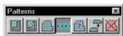
Used to draw a pattern along a linear element.
The pattern cell (top) and the element (bottom) used for the illustrations in the table below.
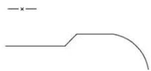
natural_image
Simple line drawing with a horizontal line and a curved shape, no text or symbols present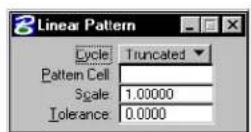
| Tool Setting | Effect |
| Cycle Sets | the manner in which the active Pattern Cell is placed.Truncat ed—Place along the element at the Active Pattern Scale. If necessary, the last instance is truncated.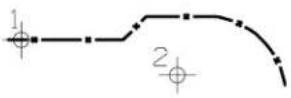 Complete —Placed along the element at a scale that is adjusted, if necessary, from the Active Pattern Scale so that only complete instances are placed. Complete —Placed along the element at a scale that is adjusted, if necessary, from the Active Pattern Scale so that only complete instances are placed.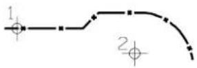 |
| Cycle | Single—Placed with one instance on each segment.1If a segment's length is less than 80% of the cycle length, the segment is patterned with the first horizontal line in the pattern cell.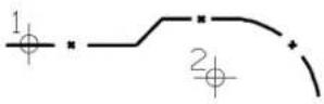 Multiple —Place along an element at a scale that is adjusted, if necessary, from the Active Pattern Scale so that every instance is complete along each segment. If a segment's length is less than 80% of the cycle length, the segment is patterned with the first horizontal line in the pattern cell. Multiple —Place along an element at a scale that is adjusted, if necessary, from the Active Pattern Scale so that every instance is complete along each segment. If a segment's length is less than 80% of the cycle length, the segment is patterned with the first horizontal line in the pattern cell.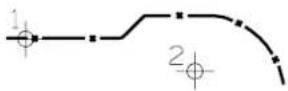 |
| Pattern Cell | The cell that is tiled to create the pattern. Can also be set with the Pattern button in the Cell Library dialog box (Element menu > Cells). |
| Browse Cells | Opens the Cell Libraries dialog box for purposes of placement of a different active cell. |
| Scale | The active Pattern Cell is scaled by this factor.2 |
1 A line, arc, curve, or ellipse; or each segment of a line string, shape, complex chain, or complex shape.
2 If between 0–1 (for example, 0.25), the size is decreased. If 1, the size is unchanged from the cell definition. If greater than 1, the size is increased.
| Tool Setting Effect | |
| To le r a n c e page 5-38) | (s Maximum distance between a curved element and the approximating line segments. |
To pattern a linear element
- Select the Linear Pattern tool.
- Identify the element.
- Enter a data point to indicate the pattern direction.
Key-in: PATTERN LINE[SINGLE | MULTIPLE | ELEMENT | SCALE]
√ Linear patterning is supported to maintain compatibility with existing applications and for customers who have existing designs with linear patterns. In most cases, however, defining a Custom Line Style (see page 2-6) and using linear element placement tools is far more efficient, and is recommended for new design work.
Show Pattern Attributes

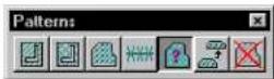
Used to display the Pattern Angle and Pattern Scale attributes of a pattern element.
To display the angle and scale of a pattern element
- Select the Show Pattern Attributes tool.
- Identify the pattern element.
The element highlights, and its type and level display
in the status bar.
- Accept the element.
The pattern angle and scale are displayed in the status bar.
Key-in: SHOWPATTERN
Match Pattern Attributes

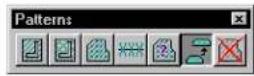
Used to set the active pattern settings (Angle, Scale, and Spacing) to match the attributes of a pattern element in the DGN file.
To match the active pattern settings to those of an existing pattern element
- Select the Match Pattern Attributes tool.
- Identify the pattern element.
- Accept the pattern element.
The new active pattern settings are displayed in the status bar.
Key-in: ACTIVE PATTERN MATCH
Delete Pattern

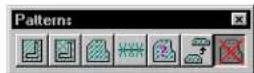
Used to delete patterning.
To delete patterning
- Select the Delete Pattern tool.
- Identify the patterning to delete or, in the case of associative patterning, the patterned element.
- Accept the deletion.
Key-in: DELETEPATTERN
Dimension-driven Cells
Cells have many uses: They can save time drawing repeated details, make it easy to update details throughout a design, provide uniformity in a project, and so on. Although they can be modified, most cells are placed as static parts of a DGN file.
A dimension-driven cell has special "intelligence." It is not static, but dynamically changes based on relationships that were defined when it was created. A cell in the DGN file that is based on a dimension-driven cell is called a derived cell.
For information about creating dimension-driven cells, see "Dimension-driven Cells" in the Administrator Guide.
In DWG workmode, by default, dimension-driven design
tools are disabled.
To place a derived cell
- Make the dimension-driven cell the active cell.
- Key in MDL LOAD DDCELL.
- Key in PLACE CELL DIMENSION.
The Dimension-Driven Design dialog box opens. A list box with each dimension or constant's initial value (the value stored in the library cell) is displayed.
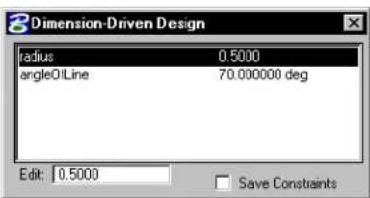
text_image
Dimension-Driven Design radius 0.5000 angleOLine 70.000000 deg Edit: 0.5000 Save Constraints- (Optional) — For each dimension or constant you want to change, select it in the list box, press Tab , and key in the new value in the Edit field.
If the cell is visible in a view, the changes display dynamically.
- (Optional) — To place the cell with active constraints so it can be modified after placement, turn on Save Constraints.
- Enter a data point to position the cell's origin.
The cell is derived and placed. If the cell cannot be derived from the supplied dimension and constant values, the cell is not placed, and you are prompted to enter new values.

Dimensions can be tagged by a constant or, if not, appear in the list labelled as "DIMENSION."
To modify a derived cell
- Key in MDL LOAD DDCELL.
- Key in MODIFY DIMENSIONS.
- Identify the cell.
The Dimension-Driven Design dialog box opens. A list box with each dimension or constant's value is displayed.
- For each dimension or constant you want to change, select it in the list box, press Tab , and key in the new value in the Edit field.
- Enter a data point to modify the cell.
If the cell cannot be derived from the supplied dimension and constant values, the cell is not modified and you are prompted to enter new values.
text_image
6References
A reference attachment is a model attached to and displayed with the active model for plotting or construction purposes. A reference cannot be modified. You can attach, as a reference, a model that resides in either the open DGN file or some other DGN file. This chapter covers:
• Using References (see page 6-1)
- Adjusting the File Update Sequence (see page 6-43)

User preferences that affect reference operations are set by choosing Preferences from the Workspace menu and selecting the Reference category.

To attach a raster image to the active model as a (read-only) reference, use the Raster Manager dialog box (File > Raster Manager). The next section pertains only to the attachment of models as references.

For more information on the Raster Manager dialog box, see "Raster Manager dialog box" in the Reference Guide.
Using References
Elements in a reference display as though they were in the active model. Although you cannot manipulate the elements in a reference, you can snap to them and even copy them into the active model.
It is sometimes convenient to refer to one part of a model while drawing in another area by attaching the active model to itself.
Attaching references
The most common way to attach a reference is to attach it coincidentally, which means that the coordinates of the referenced model's design plane are aligned with those of the active model, without any rotation, scaling, or offset.
To attach a reference coincidentally
- From the File menu, choose Reference.
The References dialog box opens.
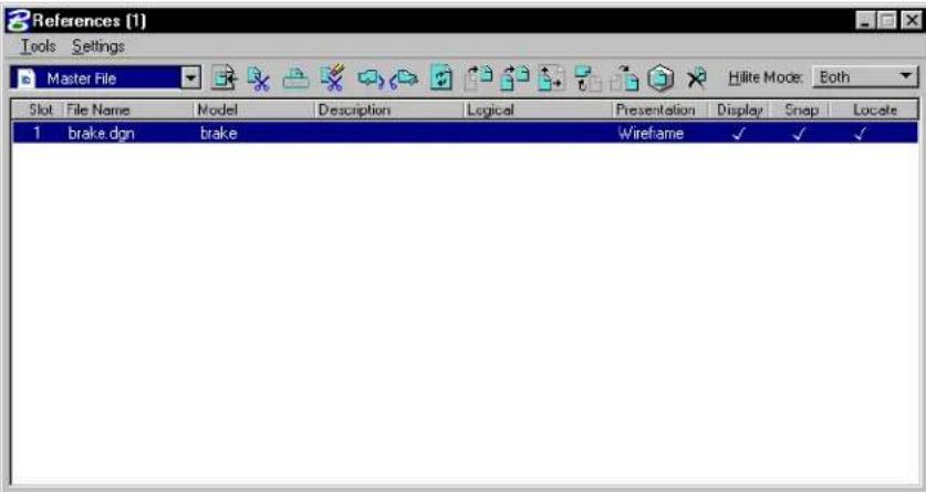
text_image
References (1) Tools Settings Master File Hilite Mode: Both Slot File Name Model Description Logical Presentation Display Snap Locate 1 brake.don brake Wireframe ✓ ✓ ✓- From the dialog box's Tools menu, choose Attach.
or In the Reference dialog box, right-click in the list box and choose Attach from the pop-down menu.
The Attach Reference dialog box opens.

text_image
Attach Reference File Directory Files: FlangedValve.dgn BikeFrame.dgn Constraints.dgn FlangedValve.dgn FlowTags.dgn Directories: ...projects\Examples\General\dgn\ D:\ Bentley Workspace projects Examples General dgn 2D - V8 DGN List Files of Type: CAD Files (*.dgn,*.dwg*,.dxf) Save Relative Path Drives: D: DWG Options OK Cancel- Select the DGN file that contains the model to attach as a reference and click OK.
The Attach References Setting dialog box opens.
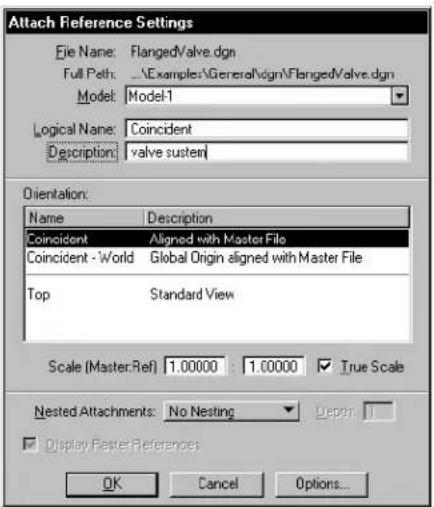
text_image
Attach Reference Settings File Name: FlangedValve.dgn Full Path: ..\Examples\General\dgn\FlangedValve.dgn Model: Model-1 Logical Name: Coincident Description: valve susten Orientation: Name Description Coincident Aligned with Master File Coincident - World Global Origin aligned with Master File Top Standard View Scale (Master.Ref) 1.00000 1.00000 True Scale Nested Attachments: No Nesting Display Master References OK Cancel Options...-
(Optional) — In the Model option menu, select the model to attach. The default is the reference's master model.
-
(Optional) — (unless the selected model is already attached) In the Logical Name field, key in a brief name for the attachment.
-
(Optional) — In the dialog box's Description field, key in a description of the model.
-
In the Orientation list box, select Coincident.
-
(Optional) — In the Scale (Master:Ref) fields, define the ratio of the active model's Master Units to the referenced model's Master Units. For example:
| To set | Left Right | |
| One active model master per referenced model master unit (the default). | 1unit | 1 |
| Five active model master units per referenced model master unit. | 5 | 1 |
-
Turn on the True Scale check box if you want the units in the active model to align one to one with units in the reference.
-
Click OK.

Since the same model can be attached many times, give the references logical names and descriptions that help you remember which reference is which.
Attachments using saved views
Attaching references can be a useful way to set up a drawing for printing. In composing the drawing, you can attach only the portion of a model in a saved view. This process can be automated using
6-4 MicroStation User Guide
the techniques covered in Drawings of 3D Models.

For more information on attaching references, see "Composing Sheet Models with References" in the Guide to Generating Drawings.

For information about saved views, see "Using Saved Views" in the QuickStart Guide.
Toattachareferenceusingasavedview
- Follow steps 1–6 in the procedure To attach a reference coincidentally (see page 6-2).
- In the Orientation list box within the Attach Reference Settings dialog box, select the saved view.
Selecting a saved view
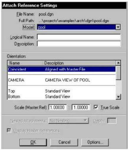
text_image
Attach Reference Settings File Name: pool.dgn Full Path: ..\projects\examples\arch\dgn\pool.dgn Model: pool Logical Name: Description: Orientation: Name Description Coincident Aligned with Master File CAMERA CAMERA VIEW OF POOL Top Standard View Bottom Standard View Scale (Master.Ref) 1.00000 1.00000 True Scale Nested Attachments: No Nesting Display Master-References OK Cancel Options...- (Optional) — In the Scale (Master:Ref) fields, define the ratio of the active model's Master Units the referenced
model's Master Units. For example:
| To set | Left Right | |
| One a ct iv e m o d e l m a s t e per referenced model master unit (the default). | i unit | 1 |
| Five active model master units per referenced model master unit. | 5 | 1 |
-
(Optional) — Turn on the True Scale check box if you want the units in the active model to align one to one with units in the reference.
-
Click OK.
The area of the reference's saved view dynamically displays as a rectangle centered about the pointer.
- Enter a data point to position the center of the saved view.

Since the same model can be attached many times, you should give the references unique logical names and descriptions to help you remember which reference is which.
To attach the active model to itself as a reference
- From the File menu, choose Reference.
The References dialog box opens.
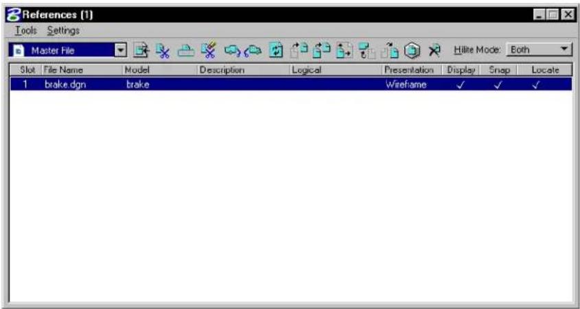
text_image
References (1) Tools Settings Master File Hilite Mode: Both Slot File Name Model Description Logical Presentation Display Snap Locate 1 brake dgn brake Wireframe ✓ ✓ ✓- From the dialog box's Tools menu, choose Attach.
or
In the Reference dialog box, right-click in the list box and choose Attach from the pop-down menu.
The Attach Reference dialog box opens.
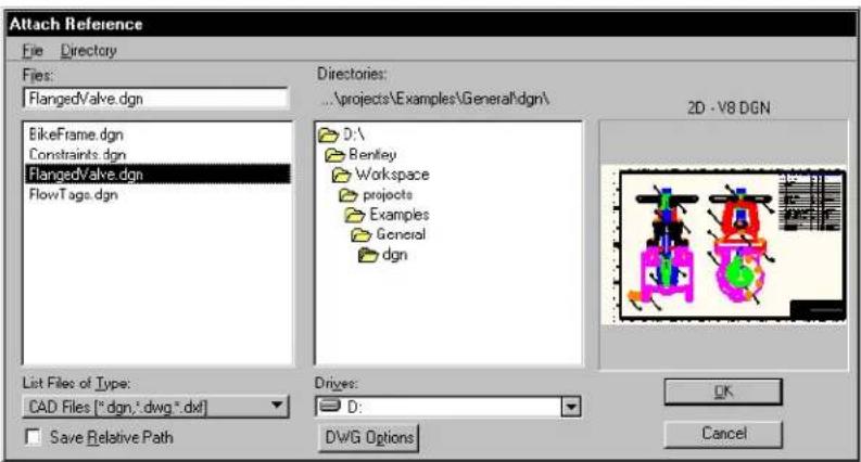
text_image
Attach Reference File Directory Files: FlangedValve.dgn BikeFrame.dgn Constraints.dgn FlangedValve.dgn FlowTags.dgn Directories: ...\projects\Examples\General\dgn\ D:\ Benley Workspace projects Examples General dgn 2D - V8 DGN List Files of Type: CAD Files ("dgn,"dwg,".dxf] Save Relative Path Drives: D: DWG Options OK Cancel- Select the DGN file that contains the model to attach as a reference and click OK.
The Attach References Setting dialog box opens.
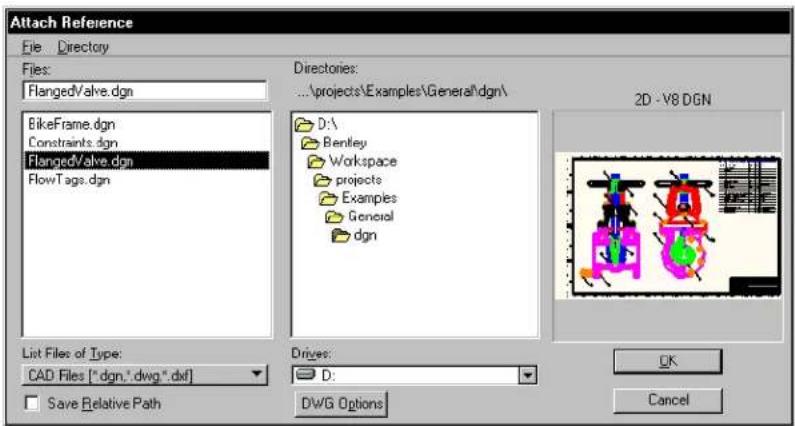
text_image
Attach Reference File Directory Files: FlangedValve.dgn BikeFrame.dgn Constraints.dgn FlangedValve.dgn FlowTags.dgn Directories: ...\projects\Examples\General\dgn\ D:\ Bentley Workspace projects Examples General dgn 2D - V8 DGN List Files of Type: CAD Files ["dgn,"dwg",dxf] Save Relative Path Drivers: D: DWG Options OK Cancel- (Optional) — In the Model option menu, select the model to attach. The default is the reference's master model.
- (Optional) — (unless the selected model is already attached) In the
Logical Name field, key in a brief name for the attachment.
- (Optional) — In the dialog box's Description field, key in a description of the model.
- Attach the model to itself coincidentally. Follow steps 4-9 in the procedure To attach a reference coincidentally (see page 6-2). or Attach a saved view. Follow steps 2-5 in the procedure To attach a reference using a saved view (see page 6-5).

The preference Allow Editing of Self Reference determines whether models that are attached to themselves (self-attached) are automatically updated to reflect modifications to the active model. Allow Editing of Self Reference is on by default. This makes it easier to use self-attached references, for example, to generate drawings of 3D models.

For more information on drawings of 3D models, see “Composing Sheet Models with References” in the Guide to Generating Drawings.
Making portable reference attachments
When a model is attached as a reference, the full path to the directory in which the DGN file containing the model resides is retained by default in the attachment information that is stored in the open DGN file. This approach allows references to be portable so they will be located by MicroStation in the following situations:
• The references are accessed across a network.
- The open DGN file and references are moved to a different directory.
- The open DGN file and references are transferred to a system with a different directory structure, or even to a different platform.
You can override the Reference File > Use Color Table user preference by creating and setting a MicroStation configuration variable. If MS_REFCOLORTABLE is defined and set to 1, MicroStation always uses the reference's color table. If MS_REFCOLORTABLE is defined and set to any value other than 1, MicroStation never
uses the reference's color table. If MS_REFCOLORTABLE is not defined, MicroStation uses the user preference to determine whether or not to use the reference's color table.
To use the most flexible technique for making portable references, you must first define a custom configuration variable whose definition specifies the directory in which references reside. For information about defining custom configuration variables, see “Working With Configuration Variables” in the Administrator Guide.
To attach a model as a reference residing in a directory specified by a custom configuration variable
- From the File menu, choose Reference.
The References dialog box opens.
- From the dialog box's Tools menu, choose Attach. or
From the Reference dialog box, right-click in the list box and select Attach from the pop-up menu.
The Attach Reference dialog box opens. Even if the model you want to attach is displayed in the Files list box, do not skip steps 3-4.
- From the dialog box's Directory menu, choose Select Configuration Variable.
The Select Configuration Variable dialog box opens.
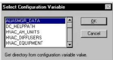
text_image
Select Configuration Variable ALIASMGR_DATA DC_HELPPATH HVAC_AH_UNITS HVAC_DIFFUSERS HVAC_EQUIPMENT OK Cancel Get directory from configuration variable value.- In the list box, select by name the configuration variable whose definition specifies the directory in which the model resides, and click OK.
In the Attach Reference dialog box, the files in the
specified directory are listed.
- In the list box, select the model to attach and click OK.
The Attach Reference Settings dialog box opens.
- Attach the model to itself coincidentally. Follow steps 1-6 in the procedure To attach a reference coincidentally (see page 6-2). or
Attach a saved view. Follow steps 1-6 of the procedure To attach a reference using a saved view (see page 6-5).
The configuration variable name is stored, along with the filename, (optional) logical name and (optional) description, in the attachment information. The variable name displays in the File Name column in the References dialog box to indicate the portable attachment.
MicroStation will locate a model attached in this manner whenever the DGN file is opened — on any system — as long as the custom configuration variable is defined and the model is stored in the specified directory. The specified directory can vary from system to system.

Portability, albeit without the same flexibility, can be achieved by defining the MS_RFDIR configuration variable rather than a custom configuration variable. MS_RFDIR specifies the directories in which MicroStation attempts to locate references after first using the attachment information (including custom configuration variables) and, failing that, searching the same directory as the active model.
Helping locate "lost" attachments
If MicroStation cannot locate a reference upon opening a DGN file, "file not found" is shown in the Full Path field when the file is selected in the Attach Reference dialog box.
To update an reference when MicroStation cannot locate the file
- From the File menu, choose Reference.
The References dialog box opens.
- In the list box, double-click the reference.
or
Select a reference in the list box, then from the Setting menu, choose Attachment.
The Attachment Settings dialog box opens.
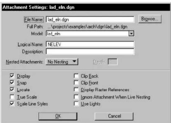
text_image
Attachment Settings: lad_eln.dgn File Name: lad_eln.dgn Full Path: ..\projects\examples\arch\dgn\lad_eln.dgn Model: lad_eln Logical Name: NELEV Description: Nested Attachments: No Nesting Depth: Display Snap Locate True Scale Scale Line Styles Clip Back Clip Front Display Raster References Ignore Attachment When Live Nesting Use Lights OK Cancel- In the File Name field, key in the new file specification. or
Click the Browse button and select the reference in the Reattach Reference dialog box. Then click OK to return to the Attachment Settings dialog box.
- Click OK.
Attaching remote references
The Remote Attach function allows you to select a URL as a DGN file location instead of a specific local DGN file.
To attach a remote reference
- From the File menu, choose Reference.
The References dialog box opens. - From the dialog box's Tools menu, choose Attach URL.
The "Select Remote DGN File dialog box" opens.
See “Select Remote DGN File dialog box” in the Reference Guide for descriptions of the controls in this dialog box. - In the URL field, specify the path to the remote reference.
- (Optional) — Adjust any other settings necessary.
- Click OK.
Reference Agent
Reference Agent enables you to automatically maintain local copies of remote references. Upon loading the Reference Agent, each attached reference is checked against a data file to see if a URL has been associated. If so, an HTTP request is automatically sent to check the last-modified date of the remote file against the local copy. If a newer copy exists at the remote URL, the status of the file changes to "Out of Date."
| Status Description | |
| N/A Reference has no associated URL. | |
| Current | Remote reference is the same age or older. |
| Unknown | Remote reference could not be found, or the last modified date was not available.Generally indicates that the URL is invalid, or that there was a network error when the remote site was contacted. |
| Out of Date | Local copy of the reference is older then the remote copy. |
References with more than one logical name have only one entry in the
Reference Agent. Downloading the associated remote URL results in the update of all logical entries associated with the local file.
To access the Reference Agent
- From the References dialog box's Tools menu, choose Ref Agent. or
From the E-Links tool box (Tools > Engineering Links), select Load RefAgent.
The Reference Agent dialog box opens.
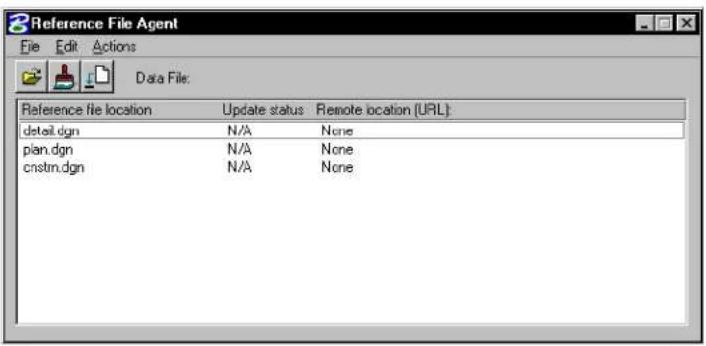
text_image
Reference File Agent File Edit Actions Data File: Reference file location Update status Remote location (URL): detail.dgn N/A None plan.dgn N/A None cnstm.dgn N/A NoneFor more information on the Reference Agent, see "Reference Agent dialog box" in the Reference Guide.
Working with attached references
Except for Attach Reference (see page 6-31), reference tools operate on the model(s) that are selected in the References dialog box. If no model is selected there, you are prompted to identify a model. See Identifying references (see page 6-26) for more information.
The Ctrl and Shift keys are used to select multiple models.

Every reference manipulation tool can contain any or all of the following tool settings. If Use Reference Dialog List (which is dimmed if the References dialog is closed or minimized) is selected, the
manipulation works on the models selected in the Reference dialog box. If Use Fence is selected (and a fence exists) any model(s) that are in the fence are manipulated. If a selection set has been created, manipulation works on the models in that set.
To turn the display of a reference off or on
- In the References dialog box's list box, click the Display column of the entry for the reference.
Alternative method — To turn the display of a reference off or on
- From the References dialog box's Settings menu, choose Attachment. or In the References dialog box's list box, double-click the reference.
The Attachment Settings dialog box opens for the selected reference.
- Turn the Display check box off or on.
For information on turning on or off symbology in a reference, see "To control level symbology" on page 1-14.
To turn snapping to elements in a reference on or off
- In the References dialog box's list box, click the Snap column of the entry for the model.
Alternative method — To turn snapping to elements in a reference on or off
-
From the References dialog box's Settings menu, choose Attachment or In the References dialog box's list box, double-click the reference. The Attachment Settings dialog box opens for the selected reference.
-
Turn the Snap check box off or on.
To control whether elements in a reference can be identified (for construction)
- In the References dialog box's list box, click the Locate column of the entry for the reference.
Alternative method — To control whether elements in a reference can be identified (for construction)
-
From the References dialog box's Settings menu, choose Attachment. or In the References dialog box's list box, double-click the reference. The Attachment Settings dialog box opens for the selected reference.
-
Turn the Locate check box on or off.
To change a reference's logical name or description
-
From the References dialog box's Settings menu, choose Attachment or In the References dialog box's list box, double-click the reference. The Attachment Settings dialog box opens.
-
In the Logical Name field, enter the new logical name.
- In the Description field, enter the new description.
- Click OK.
To move a reference selected from the Reference Dialog List
- In the References dialog box's list box, select the reference(s) you want to move in the active model.
- Turn on Display, Snap, and Locate.
- Select the Move Reference tool. or
From the Tools menu, choose Move.
- In the Move Reference settings window, turn on Use Reference Dialog List.
- Enter a data point to begin, and drag the reference. Then enter a data point to place the moved reference.
To move a reference from the contents of a fence
- Place a fence around the area containing the reference(s) to be moved.
- Select the Move Reference tool. or From the Tools menu, choose Move.
- In the Move Reference settings window, turn on Use Fence and set the desired fence mode.
- Enter a data point to begin the move, and drag the model to the desired location. Then enter a data point to place the moved reference(s).
To copy elements from a reference to the active DGN file
- In the References dialog box's list box, select the reference in which the elements are located.
- Turn on Display, Snap, and Locate.
- Select or fence the elements to be copied.
- In the Manipulate tool box, select the Copy tool (see page 4-26).

- Enter a data point to define the origin of the elements to be copied. The elements are dynamically displayed as the pointer is moved about the screen.
- Enter a data point to define the origin of the copies of the elements in the active model.
To make a copy of a reference selected from the Reference Dialog List
- In the References dialog box's list box, select the reference(s) you want to make a copy of in the active model.
- Turn on Display, Snap, and Locate.
- Select the Copy Reference Attachment tool. or From the Tools menu, choose Copy.
- In the Copy Reference Attachment settings window, turn on Use Reference Dialog List.
- Enter a data point to begin the copy. Then drag the reference and enter a data point to place the copied model.
To make a copy of a reference from the contents of a fence
- Place a fence around the area containing the reference(s) to be copied.
- Select the Copy Reference Attachment tool. or From the Tools menu, choose Copy.
- In the Copy Reference Attachment settings window, turn on Use Fence and set the desired fence mode.
- Enter a data point to begin the copy, and drag the reference to the desired location. Then enter a data point to place the copied model(s).
To scale a reference(s) selected from the Reference Dialog List
- In the References dialog box's list box, select the reference(s) you want to scale in the active model.
-
Turn on Display, Snap, and Locate.
-
Select the Scale Reference tool.
or From the Tools menu, choose Scale.
- In the Scale Reference settings window, set the scaling Method (and scale factor or ratio, if applicable).
- Turn on Use Reference Dialog List.
- Enter a data point about which the reference is scaled.
To scale a reference(s) selected from the contents of a fence
- Place a fence around the area containing the reference(s) to be scaled.
- Select the Scale Reference tool. or From the Tools menu, choose Scale.
- In the Scale Reference settings window, set the scaling Method (and Scale Factor or ratio, if applicable).
- Turn on Use Fence and set the desired fence mode.
- Enter a data point about which the reference(s) is scaled.
To rotate a reference(s) selected from the Reference Dialog List
- In the References dialog box's list box, select the reference(s) you want to rotate in the active model.
- Turn on Display, Snap, and Locate.
- Select the Rotate Reference tool. or From the Tools menu, choose Rotate.
- In the Rotate Reference settings window, set the rotate Method (and X, Y, Z coordinates if method is By Angle).
- Turn on Use Reference Dialog List.
- Enter a data point about which the reference(s) is rotated.
To rotate a reference(s) selected from the contents of a fence
- Place a fence around the area containing the reference(s) to be rotated.
- Select the Rotate References tool.
or
From the Tools menu, choose Rotate.
The Rotate Reference dialog box opens. - Select a rotate method (and X, Y, Z coordinates if method is By Angle).
- Select Use Fence and the desired fence mode.
- Enter a data point about which the reference(s) is rotated.
To mirror a reference(s) selected from the Reference Dialog List
- In the References dialog box's list box, select the reference(s) you want to mirror in the active model.
- Turn on Display, Snap, and Locate.
- Select the Mirror Reference tool. or
From the Tools menu, choose Mirror Horizontal or Mirror Vertical.
The appropriate Mirror Reference dialog box opens.
- If the Mirror Reference tool was selected, select the desired method: About Vertical Line or About Horizontal Line.
- Select Use Reference Dialog List.
- Enter a data point about which the reference is to be mirrored.
To mirror a model(s) selected from the contents of a fence
- Place a fence around the area containing the reference(s)
to be mirrored.
- Turn on Display, Snap, and Locate.
- Select the Mirror Reference tool. or From the Tools menu, choose Mirror Horizontal or Mirror Vertical. The appropriate Mirror Reference dialog box opens.
- If the Mirror Reference tool was selected, choose the desired method: About Vertical Line or About Horizontal Line.
- Select Use Fence and the desired fence mode.
- Enter a data point about which the reference is to be mirrored.
To define a reference clipping boundary (outside boundary of the displayed area) using a fence
- To define the reference clipping boundary's position, place a fence with the Place Fence tool over the desired clip area.
- Select the Set Reference Clip Boundary tool. The Set Reference Clip Boundary dialog box opens.
- Select Fence in the Method field.
- If Use Reference dialog is on, select the model(s), from the References dialog box, the clip boundary set will affect. If off, all models that fall within the clip boundary will be clipped.
- Select a model within the fence.
- Accept the clip reference.
To define a reference clipping boundary (outside boundary of the displayed area) using an element
- To define the reference clipping boundary's position, place an element over the desired clip area.
- Select the Set Reference Clip Boundary tool. The Set Reference Clip Boundary dialog box opens.
- Select Element in the Method field.
- If Use Reference dialog is on, select the reference(s), from the
References dialog box, the clip mask will affect. If off, all references that fall within the clip mask will be clipped.
- Identify the element as the clipping element.
- Accept the element as the clipping element.
- Identify the reference within the clip area.
- Accept the clip boundary.

You can not create clip masks if an element was used to create a clip boundary. Clip masks can only be created from clip boundaries created using a fence.

The boundaries of a saved view can be used as the clipping boundary when a reference is attached (see "To attach a reference DGN file using a saved view" on page 6-5).
These view attributes that affect how clipped references are displayed are set in the View Attributes dialog box (Settings menu > View Attributes).
| View Attribute | Effect |
| Ref(erence) Boundaries | If on, reference clipping boundaries are displayed in the view as a dashed line. |
| Fast Ref(erence) Clipping | If on, all attached references are clipped to rectangular boundaries, which are orthogonal to the view and enclose the boundary points. If off, the reference is displayed and plotted as specified by a non-rectangular clipping boundary. |

To place a reference clipping mask that covers part of the reference that is inside the clipping boundary
- To define the reference clipping mask's position, place a
fence with the Place Fence tool.
- Select the Set Reference Clip Mask tool.
The Set Reference Clip Mask dialog box opens. - If Use Reference dialog is on, select the model(s) from the References dialog box the clip mask will affect. If off, all models that fall within the clip mask will be clipped.
- Select the model within the fence.
- Accept the clip mask.
Clipping masks can only be created within clipping boundaries created using a fence.
More than one clipping mask can be specified for a reference. Reference elements display only if they are inside the clipping boundary and outside all clipping masks.
To selectively delete a reference's clipping mask(s)
- Select the Delete Reference Clip tool.
The Delete Reference Clip dialog box opens.
- If Use Reference dialog is on, select the reference(s) from the References dialog box that contain the clip mask. If off, identify the model by entering a data point within the clip boundary that contains the clip mask.
The clip boundary and any clip masks within the boundary highlight.
- Identify the clipping mask to be deleted.
A clipping mask is highlighted for deletion.
- Accept the deletion.
or
Reset to keep the highlighted clipping mask.
The next clipping mask, if any, is highlighted for deletion.
- Repeat step 3 for each subsequent clipping mask.
When you select a reference (or have one selected from the selection set, fence or dialog box), the reference is highlighted. If there is a clip boundary and one or more mask, the boundary is
showninyellowandthemasksshowninred.
To define a reference front clipping plane (3D only)
- Select the Set Reference Front Clip Plane tool.
The Set Reference Front Clip Plane dialog box opens. - If Use Reference dialog is on, select the reference(s) from the References dialog box that will be affected by the front clipping plane. If off, all references that intersect the front clipping plane will be affected.
- Enter a data point to define the front clipping plane depth.
The reference updates with the new clipping plane.
To define a reference back clipping plane (3D only)
- Select the Set Reference Back Clip Plane tool.
The Set Reference Back Clip Plane dialog box opens. - If Use Reference dialog is on, select the reference(s) from the References dialog box that will be affected by the front clipping plane. If off, all references that intersect the front clipping plane will be affected.
- Enter a data point to define the back clipping plane depth.
The reference updates with the new clipping plane.
To update reference elements in a view
- Key in REFERENCE UPDATE.
- Identify the reference by identifying one of its elements. or Identify the reference by keying in its logical name or filename in the Key-in window.
To reload a reference
- In the list box in the References dialog box, select the reference.
- Select the Reload Reference tool.
or
From the Tools menu, choose Reload.
The reference is redrawn.

Reloading a reference lets you see changes that have been made to the reference by a co-worker on the network since the reference was last attached or reloaded.
To reload alltached references
- In the list box in the References dialog box, select the reference.
- Select the Reload Reference tool.
or
From the Tools menu, choose Reload All.
The reference is redrawn. - In the list box in the References dialog box, select the reference.
- From the dialog box's Tools menu, choose Reload All.
The references are read from the disk and redrawn.

Reloading references lets you see changes that have been made to these references by a co-worker on the network since they were last attached or reloaded.
To detach a reference
- In the References dialog box's list box, select the reference.
- Select the Detach Reference tool.
or
From the Tools menu, choose Detach.
An alert box asks you to confirm that the selected reference(s) is to be detached. - Click OK.
To detach all references
-
From the Tools menu, choose Detach All. An alert box asks you to confirm that all references are to be detached.
-
Click OK.
Alternative method — To detach all references
- In the References dialog box's list box, select all of the references.
- Select the Detach Reference tool.
An alert box asks you to confirm that the selected reference(s) is to be detached. - Click OK.
Identifying references
Identifying a reference on which to operate is an alternative to selecting the reference in the References dialog box's list box; the identification technique is typically used with tools in the References tool box (see page 6-28).
To identify a reference
- In a view window, identify an element in the reference.
Merging reference DGN files
It is possible to merge a DGN file and all attached references into a single output file. Merging ensures that all data attached to a single DGN file (all views, angles of views, rendering settings, and other settings) are stored in a single location. The result of a merging operation is effectively a snapshot of the DGN file.
This capability is especially useful for plotting active files, where many users are frequently changing a file's composition, views, settings, and attachments.
To merge the active model and an attached reference(s)
- In the References dialog box's list box, select the reference(s) to be merged.
- From the Tools menu, choose Merge Into Master.
An alert box asks you to confirm that the selected reference(s) is to be merged into the active model.
- Click OK.
To merge the active model and all attached references via Key-in
- Key in MDL LOAD REFMERGE.
The last view in which a data point was entered is processed. Only the displayed levels of the processed view are copied to the output file. This output file has the same name as the active model, but with the extension ".rcd" (which stands for "record drawing").
To merge reference DGN files from the system command line
- Exit MicroStation.
- Set the system environment variable MS_INITAPPS to "refmerge."
- Start MicroStation with the following command line:
ustation:v
For example, ustation:v2 *.dgn processes all the DGN files in the current directory and uses view 2 as the source view.
Be sure to unset the system environment variable MS_INITAPPS when the operation is complete.
There is no inverse of a reference DGN file merging operation.
Setting the render mode of a reference
It is possible to set different display modes for references using the Set Reference Presentation tool.
To set the render mode of a reference
- Select the Set Reference Presentation tool.
The Set Reference Presentation dialog box opens. - Select the method of display in the Presentation field.
- If Use Reference dialog is on, select the reference(s) from the References dialog box that the presentation will affect. If off, identify a reference by entering a data point on the reference that the presentation will affect.
- Accept the reference.
The reference is displayed using the select presentation method.
References tool box
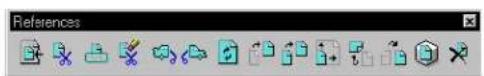
The tools in the References tool box (Tools menu >References) are used to:
- Attach referenced models to the active model.
• Control the positioning, scaling, and orientation of attached referenced model. - Detach referenced models from the active design file.
These tools can also be selected in these ways:
- From the Tools menu in the References dialog box (File menu > Reference). The controls in the References dialog box are
used to adjust reference settings as well.
- From the Icons on the References dialog box ( File menu > Reference).
Key-in: DIALOG REFERENCE
| To | Select in the Reference tool box |
| Attach a model to the active model. |  Attach Reference (see page 6-31) Attach Reference (see page 6-31) |
| Change a reference clipping boundary. |  Set Reference Clip Boundary (see page 6-32) Set Reference Clip Boundary (see page 6-32) |
| Mask (cover) part of a model that is inside the clipping boundary. |  Set Reference Clipping Mask (see page 6-33) Set Reference Clipping Mask (see page 6-33) |
| Selectively delete a reference's clipping mask(s). |  Reference Clip Mask Delete (see page 6-33) Reference Clip Mask Delete (see page 6-33) |
| Set the back clipping plane for a 3D model. |  Set Reference Back Clip Plane (see page 6-34) Set Reference Back Clip Plane (see page 6-34) |
| Set the front clipping plane for a 3D reference. |  Set Reference Front Clipping Plane (see page 6-35) Set Reference Front Clipping Plane (see page 6-35) |
| Reread and redraw a model to see recent changes made to it. |  Reload Reference (see page 6-36) Reload Reference (see page 6-36) |
| Move a model. |  Move Reference (see page 6-36) Move Reference (see page 6-36) |
| Copy a model. |  Copy Reference Attachment (se page 6-38) Copy Reference Attachment (se page 6-38) |
| Scale a model. |  Scale Reference (see page 6-38) Scale Reference (see page 6-38) |
| Rotate a model. |  Rotate Reference (see page 6-39) Rotate Reference (see page 6-39) |
| Mirror a model about a horizontal or vertical axis. |  Mirror Reference (see page 6-40) Mirror Reference (see page 6-40) |
| Sets the rendering mode of the model. |  Set ReferencePresentation (see page 6-42) Set ReferencePresentation (see page 6-42) |
| Detach a model from the active model. |  Detach Reference (see page 6-42) Detach Reference (see page 6-42) |
Attach Reference

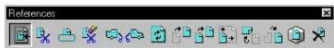
Used to attach a model to the active model. See "Attaching reference design files" on page 6-2.

text_image
Attach Reference File: Directory Files: FlangedValve.dgn BikeFrame.dgn Constraints.dgn FlangedValve.dgn FlowTags.dgn Directories: ...\projects\Examples\General\dgn\ D:\ Berkeley Workspace projects Examples General dgn List Files of Type: CAD Files (*.dgn,*.dwg,*.dxf) Save Relative Path Drives: D: DWG Options 2D - V8 DGN OK CancelThe controls of the Attach Reference dialog box are analogous to those in the Open dialog box, which opens when Open... is chosen from the File menu.

Reference attachments can be created from saved views with the camera on. This creates an attachment with its own camera so the attachment will appear identical to the saved view. This can be valuable when creating detail sections on sheets. However, since these attachments are 3D projections to 2D images, they are only
allowed in 2D master files and sheet models.
Set Reference Clip Boundary

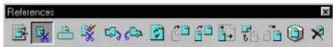
Used to define a reference clipping boundary. See the procedure "To define a reference clipping boundary (outside boundary of the displayed area)" in "Working with attached references" on page 6-14.
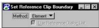
| Tool Setting | Effect |
| Method: | Determines the method by which the reference clip boundary is set.Element—Clip boundary is set by select-ing an element.Fence—Clip boundary is set by the contents of a fence. |
| Use Reference Dialog List | If on, the model(s) selected on the References dialog box is used to select a clip boundary. |
Set Reference Clipping Mask

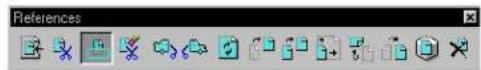
Used to place a reference clipping mask. See the procedure "To place a reference clipping mask that covers part of the reference that is inside the clipping boundary" on page 6-22.
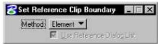
| Tool Setting | Effect |
| Use Reference Dialog List | If on, the model(s) selected on the References dialog box is used to select a clip mask. |
Key-in: REFERENCE CLIP MASK
Delete Reference Clipping Mask(s)

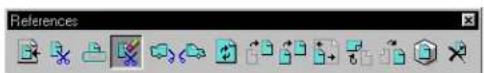
Used to selectively delete a clipping mask(s). See the procedure "To selectively delete a reference's clipping mask(s)" on page 6-23.
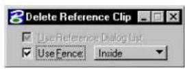
| Tool Setting | Effect |
| Use Reference Dialog List | If on, the model(s) selected on the References dialog box is deleted from the clip mask. |
| Use Fence | If on, the fence contents are deleted from the clip mask. The option menu sets the Fence (Selection) Mode. |
Define Reference Back Clipping Plane

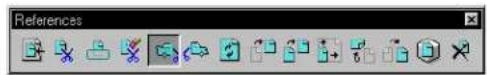
Used to set the back clipping plane for a 3D model. See the procedure "To define a reference back clipping plane (3D only)" on page 6-24.

| Tool Setting | Effect |
| Use Reference Dialog List | If on, the model(s) selected on the References dialog box is used to set the back clip plane. |
| Use Fence | If on, the fence contents are used to set the back clip plane. The option menu sets the Fence (Selection) Mode. |
Define Reference Front Clipping Plane

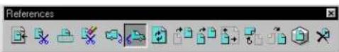
Used to set the front clipping plane for a 3D model. See the procedure "To define a reference front clipping plane (3D only)" on page 6-24.
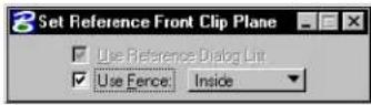
| Tool Setting | Effect |
| Use Reference Dialog List | If on, the model(s) selected on the References dialog box is used to set the front clip plane. |
| Use Fence | If on, the fence contents are used to set the front clip plane. The option menu sets the Fence (Selection) Mode. |
Reload Reference

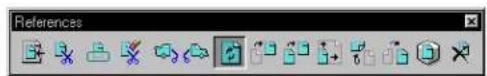
Used to reread and redraw a model. See the procedure "To reload a reference" on page 6-25.
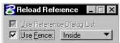
Move Reference

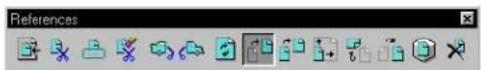
Used to move a model. See the procedure "To move a reference" in "Working with attached references" on page 6-14.
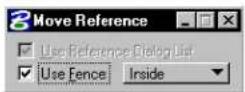
| Tool Setting | Effect |
| Use Reference Dialog List | If on, the model(s) selected on the References dialog box is moved. |
| Use Fence | If on, the fence contents are moved. The option menu sets the Fence (Selection) Mode. |
Copy Reference Attachment

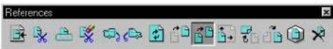
Used to copy attached references. See "Working with Attached references" on page 6-14.

Scale References

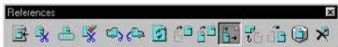
Used to scale a model. See the procedure "To scale a reference" in "Working with attached references" on page 6-14.
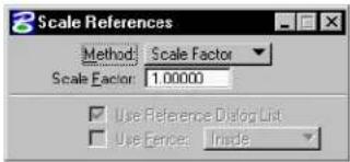
text_image
3 Scale References Method: Scale Factor Scale Factor: 1.00000 Use Reference Dialog List Use Fences: Inside| Tool Setting | Effect |
| Method | Method by which the referenced model is scaled. Scale Factor—Model is scaled by a specified factor. Absolute Ratio—Model is scaled by a specified ratio. By Points—Model is scaled by points entered. |
| Scale Factor | If Method is Scale Factor, sets the factor by which the model is scaled. For example, 2.00000 doubles the size of the model. |
| Scale (Master:Ref) | If Method is Absolute Ratio, sets the ratio of active model's Master Units to the referenced model's master units. For example, to set five active model master units for each referenced model master unit, key in 5 in the left-hand field and 1 in the right-hand field. |
| Use Reference Dialog List | If on, the model(s) selected on the References dialog box is scaled. |
| Use Fence | If on, the fence contents are scaled. The option menu sets the Fence (Selection) Mode. |
Rotate Reference

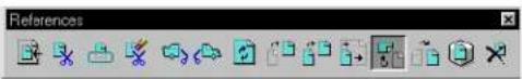
Used to rotate a model. See "Working with Attached references" on page 6-14.
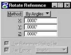
text_image
Rotate Reference Method By Angles X: 0.000° Y: 0.000° Z: 0.000° Use Reference Dialog List Use Range: Inside| Tool Setting | Effect |
| Method | Sets the method by which the model is rotated.By Angles—Sets the rotation angle(s). In 2D, sets the rotation angle(s) on the z-axis only. In 3D, sets the rotation angle(s) on the x-, y-, and z axes.By Points—Sets the point about which the model is rotated. |
| X | Angle to rotate the model about the x axis for 2D files. |
| Y | Angle to rotate the model about the y axis for 3D files. |
| Z | Angle to rotate the model about the z axis for 3D files. |
| Use Reference Dialog List | If on, the model(s) selected on the References dialog box is rotated. |
| Use Fence | If on, the fence contents are rotated. The option menu sets the Fence (Selection) Mode. |
Mirror References

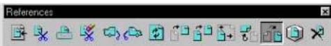
Used to mirror a model about a vertical or horizontal axis. See the procedure "To mirror a reference(s) selected from the Reference Dialog List" in "Working with attached references" on page 6-14.
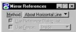
| Tool Setting | Effect |
| Method: | Sets the method by which the model is mirrored.About Horizontal Line—Used to mirror models about a horizontal axis.About Vertical Line—Used to mirror models about a vertical axis. |
| Use Reference Dialog List | If on, the model(s) selected on the References dialog box is mirrored. |
| Use Fence | If on, the fence contents are mirrored. The option menu sets the Fence (Selection) Mode. |
Set Reference Presentation

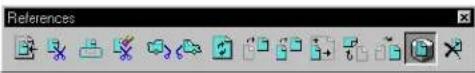
Used to set the display of a model. See "Setting the render mode of a reference" on page 6-28.
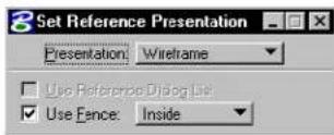
| Tool Setting | Effect |
| Presentation: | Sets the rendering mode of a model.See Rendering Modes for information on the types of rendering modes in the Visualization Guide. |
| Use Reference Dialog List | If on, the model(s) selected on the References dialog box is rendered using the selected Rendering Mode. |
| Use Fence | If on, the fence contents are rendered. The option menu sets the Fence (Selection) Mode. |
Detach Reference

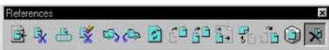
Used to detach a model from the active model. See the procedure "To detach a reference" on page 6-25.
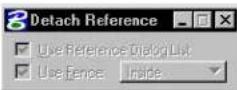
| Tool Setting | Effect |
| Use Reference Dialog List | If on, the model(s) selected on the References dialog box is detached from the master file. |
| Use Fence | If on, the models contained by the fence are detached from the master file. The option menu sets the Fence (Selection) Mode. |
Adjusting the File Update Sequence
When updating a view, MicroStation follows, by default, the following update sequence:
- the active model, and then
- the references, roughly in their attachment order.
You can customize the update sequence used with the active model using the Update Sequence dialog box. The customization capability is used to prioritize the display of overlapping elements.
▶ Tomodify the file updatesequence
- From the References dialog box's Settings menu, choose Update Sequence.
The Update Sequence dialog box opens. The list box shows the current update sequence.
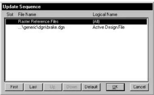
text_image
Update Sequence Slot File Name Logical Name Raster Reference Files (All) ...\generic\dgn\brake.dgn Active Design File First Last Up Down Default OK Cancel- In the list box, select one or more references or the active model. Use the Shift or Ctrl key to select a range or individual files.
- Click the First, Last, Up or Down button to move the selected files in the chosen direction on the list.
- Repeat steps 2 and 3 until the sequence is modified as desired.
- Click OK.

Changes to the update sequence are saved to the active model on disk by choosing Save Settings from the File menu.

To restore the default update sequence
- From the References dialog box's Settings menu, choose Update Sequence.
The Update Sequence dialog box opens.
-
Click the Default button.
-
Click OK.
Once this procedure is performed and DGN file settings are saved, any previous update sequence changes are lost. The alternative is to override the active model's custom update sequence with the default update sequence.

To override the custom update sequence with the default
-
From the Workspace menu, choose Preferences. The Preferences dialog box opens.
-
In the Category list box, select Reference.
-
Turn on Ignore Update Sequence.
-
Click OK.

If Ignore Update Sequence option is on, the Update Sequence item in the References dialog box's Settings menu is disabled (dimmed).
7
Advanced 2D Drafting Techniques
In this chapter, you will find procedures concerning some of the more advanced 2D operations in MicroStation, including:
• Permanently Grouping Elements (see page 7-2)
- Putting "Holes" in Solid Elements (see page 7-5)
• Using the Tools in the Fillets tool box (see page 7-6)
• Using the Tools in the Groups tool box (see page 7-8)
• Using Multi-lines (see page 7-26)
• Using the Tools in the Multi-line Joints tool box (see page 7-32)
• Associating Elements (see page 7-50)
• Isometric Drawing (see page 7-52)
• Using the Tools in the Isometric tool box (see page 7-54)
• Using Curves (see page 7-59)
• Using the Tools in the Curves tool box (see page 7-74)
• Selecting Elements Based on Attributes (see page 7-133)
• Using Auxiliary Coordinate Systems (see page 7-135)
• Using the Tools in the ACS tool box (see page 7-137)
• Digitizing (see page 7-144)
Permanently Grouping Elements
Some groupings in MicroStation, such as the set of selected elements and the fence contents, are temporary. Other groupings are permanent. These groupings include:
- levels (see "Managing Levels" on page 1-11).
- complex chains and complex shapes (see "Using complex chains and complex shapes" on page 7-2).
- groups (see "Using groups" on page 7-3).
- graphic groups (see "Using graphic groups" on page 7-4).
Using complex chains and complex shapes
A complex chain (sometimes called a "complex string") is a series of connected open elements (lines, line strings, arcs, curves) grouped for manipulation as a single entity.
A complex shape, like a complex chain, is a series of connected open elements grouped for manipulation as a single object. The difference is that the first and last element in a complex shape are connected, thereby closing a shape.
Left: Complex shape created from arc and line string with Create Complex Shape tool. Center and right: Union and intersection of circle and block created with Create Region tool.
You can create complex chains and shapes, from existing elements, with tools in the Groups tool box (see page 7-8). Also, you can use the Place SmartLine tool (see page 2-17) to create a complex shape or chain.

Complex chains and complex shapes are complex elements. A complex
element is a grouping of two or more elements that is manipulated as a single entity. Cells also are complex elements. (If you develop application software for MicroStation, you should know that a "complex header" element is stored in the DGN file for each grouping.) To reverse the grouping, you can use the Drop Element tool (see page 7-10) in the Groups tool box (see page 7-8) to drop the status of a complex element. That is, to convert the complex element to its component elements so they can be manipulated individually.
Using groups
You can select a number of elements and group them so that you can manipulate them as a single element. A group is a complex element whose component elements need not be connected.
To create a group
- Select the elements that will compose the group.
- From the Edit menu, choose Group.
The elements are grouped and will now be able to be manipulated as a single element.
▶ T o b r e a k u p a g r o u p
- Select the group.
- From the Edit menu, choose Ungroup.
The elements are ungrouped and now may be manipulated individually.
You manipulate and modify groups just as you do simple elements. For information about manipulation and modification of simple elements, see Using the Fence to Manipulate and Modify Elements (see page 3-80).

A group is actually an unnamed cell. Unlike named cells, groups are not defined in cell libraries. For this reason groups are sometimes called “orphan cells.”
Using graphic groups
Graphic groups are the most flexible grouping technique in MicroStation. Without “breaking up” the grouping, you can add, remove, or manipulate individual member elements. Whether your actions change the whole graphic group or only part of it depends upon whether you turn Graphic Group Lock on or off. With Graphic Group Lock “on”, all elements in the graphic group are manipulated. With Graphic Group Lock “off” only the selected element is manipulated.
The Groups tool box (see page 7-8) has tools for creating a graphic group and adding and removing elements to or from a graphic group.
To manipulate or modify a graphic group
- Turn on Graphic Group (Lock) in the Settings menu's Locks submenu.
- Select the appropriate tool to perform the desired manipulation or modification. See "Specialized Manipulation and Modification Tools" on page 4-11.
- Identify the graphic group.
- Continue as called for in the instructions for using the tool.
To manipulate or modify one or more member elements of a graphic group
- Use the Element Selection tool to select the element(s).

- Perform the desired manipulation or modification. See "Manipulating and Modifying Selected Elements" on page 3-77. or Select the appropriate tool to perform the desired manipulation or modification in the Manipulate tool box (see page 4-25)
or Modify tool box (see page 4-88).
- If using a specialized tool, continue as called for in the instructions for using the tool.
Alternative method — To manipulate or modify one or more member elements of a graphic group
- Turn off Graphic Group (Lock) in the Settings menu's Locks submenu.
- Select the appropriate tool to perform the desired manipulation or modification in the Manipulate tool box (see page 4-25) or Modify tool box (see page 4-88).
- Identify an element in the graphic group.
- Continue as called for in the instructions for using the tool.
Putting "Holes" in Solid Elements
When you draw a shape that represents a hole in a solid element, the interior of that shape cannot be hatched or patterned (if Associative Pattern is off), and the background will show “through” the hole.
The block is a solid; the circle and hexagon are holes, and so are not hatched (when Associative Pattern is off).
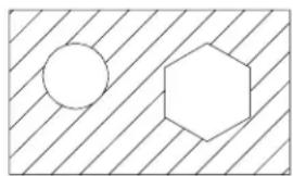
natural_image
Simple geometric diagram with a circle and a hexagon inside a rectangle, no text or symbols present.Whether a closed element is a solid or hole is determined by its Area attribute:

- The Change Element to Active Area tool (see page 4-61) in the Change Attributes tool box is used to change the Area of a closed element(s).

- The Group Holes tool (see page 7-25) in the Groups tool box is a special tool for putting holes in solid elements. The tool is so named because it creates a group consisting of the holes and the solid. In effect, this tool creates an orphan cell consisting of the outside "solid" element with the interior "hole" elements. To modify any of the elements making up the solid and holes, you first have to "drop" the group back to its constituent elements, using the Drop Element (see page 7-10) tool.
Fillets tool box
The tools in the Fillets tool box are used to fillet planar elements.
| To | Select in the Fillets tool box |
| Construct a circular fillet between two elements. |  Construct Circular Fillet (see page 4-116) Construct Circular Fillet (see page 4-116) |
| Construct a parabolic fillet between two elements. |  Construct Parabolic Fillet (see page 7-7) Construct Parabolic Fillet (see page 7-7) |
| Construct a chamfer between two lines or adjacent segments of a line string or shape. |  Construct Chamfer (see page 4-118) ^2 Construct Chamfer (see page 4-118) ^2 |
1 Also in the Modify tool box.
2 Also in the Modify tool box.
Key-in: DIALOG TOOLBOX FILLET [OFF | ON | TOGGLE]
![Bentley MicroStation V8 - Key-in: DIALOG TOOLBOX FILLET [OFF | ON | TOGGLE] - 1](/content/2026/02/423073/images/352d15b888a8725a440459c3d34d5e132b4caa1d03f622c5cc34ff0227994e3c.jpg)
To perform filleting or chamfering "on the fly," use the Place SmartLine tool (see page 2-17).
Construct Parabolic Fillet

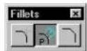
Used to construct a parabolic fillet (curve element) between two lines.
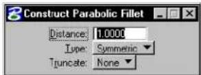
| Tool Setting | Effect |
| Distance | The distance between the points of tangency. |
| Type Sets | how the parabola is aligned:Horizontal—aligned with the horizontal view axis.Used in highway design to join intersecting grade lines. All IGDS parabolas are horizontal.Symmetric—aligned with the identified lines. |
| Truncate | Controls which line(s) are truncated.None—neither line is truncated.Both—both lines are truncated at their point of tangency with the fillet. ^1 |
If a fillet is constructed between two closed elements or an open and a closed element, the closed element(s) are not modified.
To construct a parabolic fillet
- Select the Construct Parabolic Fillet tool.
- Identify the first line.
- Identify the second line.
- Accept the fillet and truncations, if any.
Construct Parabolic Fillet. Left: Horizontal. Right: Symmetric. "D" denotes distance. Truncate is set to Both.
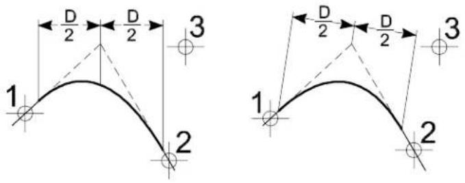
text_image
1 2 3 D/2 D/2 D/2 1 2 3Key-in: PLACE PARABOLA [HORIZONTAL | MODIFY | NOMODIFY] [MODIFY | NOMODIFY]

In 3D, both elements must be on the same plane to be filleted.

To place a B-spline curve in the form of a parabola, use the Place Conic tool (see page 7-91) in the Curves tool box.
Groups tool box
The tools in the Groups tool box are used to create and manipulate complex chains, complex shapes, and graphic groups.
| To | Select in the Groups to box |
| Break up a complex element(s) or an element(s) of a special type into simpler components. |  Drop Element (see page 7-10) Drop Element (see page 7-10) |
| Create a complex chain (open complex element). |  Create ComplexChain (see page 7-12) Create ComplexChain (see page 7-12) |
| Create a complex shape (closed complex element) from individual open elements. |  Create Complex Shape (see page 7-15) Create Complex Shape (see page 7-15) |
| Create a complex shape from the union, intersection, or difference between closed elements or by “flood fill.” |  Create Region (see page 7-18) Create Region (see page 7-18) |
| Create a graphic group.1orAdd elements to an existing graphic group.orCombine two or more graphic groups into one graphic group. |  Add to Graphic Group (see page 7-22) Add to Graphic Group (see page 7-22) |
| Remove (drop) an element(s) from a graphic group.orBreak up a graphic group into individual elements. |  Drop from Graphic Group (see page 7-23) Drop from Graphic Group (see page 7-23) |
| Select a solid element and the hole or h o l e s t o b e a s s o c i a t e d w i t h |  lid.Group Holes (see page 7-25) lid.Group Holes (see page 7-25) |
To create a group (orphan cell), select the elements and choose Group from the Edit menu. A group is not the same as a graphic group.
Key-in: DIALOG TOOLBOX GROUPS[OFF | ON | TOGGLE]
Drop Element

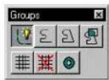
Used to break up an element(s) into simpler components. Tool settings are used to specify the element types on which the tool operates.
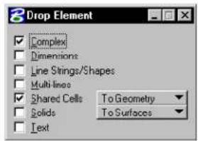
text_image
Drop Element Complex Dimensions Line Strings/Shapes Multi-lines Shared Cells To Geometry Solids To Surfaces Text| Tool Setting | Effect |
| Complex | If on, complex elements (cell, complex chain, complex shape, text node, surface, or solid) are dropped into their components. |
| Dimensions | If on, dimension element(s) are dropped into lines, line strings, ellipses, arcs, and text. |
| Line Strings/ Shapes | If on, line strings and shapes are converted to series of individual line elements. |
| Multi-lines | If on, multi-line elements are converted to sets of line strings, lines, and/or arcs. |
| Shared Cells | If on, the associated option menu lets you drop shared cells:To Geometry—They are dropped into their components.To Normal Cell—They are converted to unshared cells. |
| Solids (3D only) If on, the associated option menu lets you drop SmartSurfaces or SmartSolids:To Surfaces—They are dropped to simple surfaces.To Wireframe—They are dropped to wire-frame elements. | |
| Te x t If on, text characters in text elements are converted to the individual elements that are used to draw the characters — lines, line strings, arcs, ellipses, and shapes. | |
To break up an element into its components
- Select the element(s).
- Select the Drop Element tool.
- Turn on the appropriate tool settings to specify the element type(s) on which to operate.
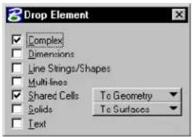
text_image
Drop Element Complex Dimensions Line Strings/Shapes Multi lines Shared Cells To Geometry Solids To Surfaces Text- Accept the settings and initiate the drop.
Only the selected elements of the specified type(s) are dropped. The tool has no effect on selected elements of other types. If
none of the selected elements is of the specified type(s), the message "Nothing to drop" displays in the status bar.
Alternative method — To break up an element into its components
- Select the Drop Element tool.
- Turn on the appropriate tool settings to specify the element type(s) on which to operate.
- Identify the element.
- Accept the drop.
Key-in: DROP ELEMENT

Drop Element cannot be used to drop elements more than one level at a time. For example, if you turn on Complex and Line Strings/Shapes and operate on a complex shape that contains two line strings, the complex shape is dropped but the component line strings are not. That is, the operation results in two line strings.
Create Complex Chain

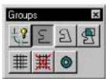
Used to create a complex chain — an open complex element that is formed from a series of open elements (lines, line strings, arcs, curves, and open B-spline curves) that can be manipulated as if it were a single primitive element. The resulting complex chain takes on the active element attributes regardless of the attributes of the component elements.
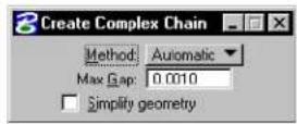
| Tool Setting | Effect |
| Method | Sets how elements are added to the complex chain:Manual—Each element is manually identified.Automatic—After the first element is identified, and accepted, if endpoints of additional open element(s) are within the Max. Gap distance of each other, they are included automatically. Where there is a choice of two or more elements (at the endpoint of an element) then the process lets you choose to either Accept the highlighted element, or Reset to see the alternative(s). |
| Max(imum)Gap | The greatest allowable distance between elements when the Method is Automatic.If zero, only elements that connect (have a common endpoint) can be added. |
| Simplifygeometry | If on, connected lines are added as line strings. If you identify only connected lines, the tool produces a primitive line string element rather than a complex chain. |
To create a complex chain manually
- Select the Create Complex Chain tool.
- Set Method to Manual.
- Identify the first element to include in the chain.
- Continue to identify elements to add to the chain.
If they are not already connected, the elements are
connected as they are identified. ^1
- Reset to complete the complex chain.
To create a complex chain automatically
-
Select the Create Complex Chain tool.
-
Set Method to Automatic.
-
Identify the first element.
-
Accept to automatically include other elements that are within the Max Gap distance. If a fork is found, where more than one element is within the Max Gap distance, the message "FORK - Accept or reset to See Alternate" displays in the status bar.
-
Enter a data point to accept the highlighted element or Reset to highlight an alternate element. Continue to reset until the desired element highlights.
-
Accept to complete the complex chain. Creation of the chain ends automatically if there are no elements within the Max. Gap.
Create Complex Chain with Method set to Automatic. After entering data point 2, the top element in the fork was highlighted (top). To highlight the alternate path, a Reset was entered (bottom).
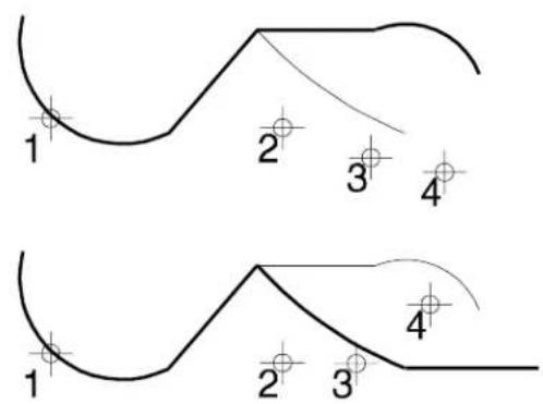
text_image
1 2 3 4 1 2 3 4Key-in: CREATE CHAIN [MANUAL | AUTOMATIC]

To convert a complex chain back to its individual components, use the Drop Element tool (see page 7-10).

It is best to create complex chains from elements that share common endpoints.

To draw a complex chain of connected arcs and line segments with one tool, use the Place SmartLine tool (see page 2-17) in the Linear Elements tool box.
Create Complex Shape

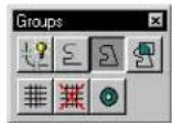
Used to create a complex shape (a closed complex element that can be manipulated as if it were one primitive element) from a series of open planar elements (lines, line strings, arcs, curves, and open B-spline curves). The resulting complex shape takes on the active element attributes regardless of the attributes of the component elements.
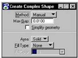
text_image
3 Create Complex Shape Method: Manual Max Gap: 0.0100 Simplify geometry Area: Solid Fill Type: None Fill Color: 1| Tool Setting Effect | |
| Method | Sets how elements are added to complex shape.Manual—Each element is manually identified.Automatic—After the first element is identified, and accepted, if endpoints of additional open element(s) are within the Max. Gap distance of each other, they are included automatically until a closed shape is created. Where there is a choice of two or more elements (at the endpoint of an element) then the process lets you choose to either Accept the highlighted element, or Reset to see the alternative(s). |
| Max(imum)Gap | The largest distance allowed between consecutive elements, if Method is Automatic.If zero, only elements that connect (have a common endpoint) can be added. |
| Simplifygeometry | If on, connected lines are added to the boundary as line strings. If you identify only connected lines, the tool produces a primitive shape element rather than a complex shape. |
| Area Sets the type of shape createdSolid—The shape created is solid (can be hatched/patterned).Hole—The shape created is a hole (cannot be hatched/patterned). | |
| Fill Type Sets | the active Fill Type.None—No fillOpaque—Filled with Active ColorOutlined—Filled with Fill Color (outline of shape takes the Active Color) |
| Fill Color | Complex shape is filled with this color if the Fill Type is Outlined; otherwise disabled (dimmed |
To create a complex shape manually
- Select the Create Complex Shape tool.
- Set Method to Manual.
- Identify the first element.
- Continue to identify elements to add to the shape.
The elements are connected as they are identified, unless they already are connected. ^2
- If the first and last elements connect, accept the shape.
If the first and last elements do not connect, Reset to close the shape and create a line element between their endpoints.
To create a complex shape automatically
- Select the Create Complex Shape tool.
- Set Method to Automatic.
- Identify the first element.
- Accept to automatically include other elements that are within the Max Gap distance.
If the elements do not have a common endpoint, they are connected. ^2
If a fork is found; that is, if more than one element is within the Max. Gap, the message "FORK – Accept or Reset to See Alternate" displays in the status bar.
- Enter a data point to accept the highlighted element. or
Reset to highlight an alternate element. Continue to Reset until the desired element highlights.
Key-in: CREATE SHAPE [MANUAL | AUTOMATIC]
If an element is accepted that is connected to the first element
identified, the complex shape is closed. If no element is found within the Max. Gap, a line element is created between the open endpoints of the first and last elements and the complex shape is closed.

To convert a complex shape back to its individual components, use the Drop Element tool (see page 7-10).

To draw a complex shape of connected arcs and line segments with one tool, use the Place SmartLine tool (see page 2-17) in the Linear Elements tool box.
Create Region

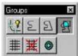
Used to create a complex shape (a closed complex element that can be manipulated as if it were one primitive element) from either of the following:
- The union, intersection, or difference between two or more closed elements.
- A region bounded by elements that have endpoints that are closer together than the Max(imum) Gap.
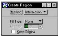
| Tool Setting | Effect |
| Method | Sets how elements are added to the complex shape and the element types from which it can be created.Intersection—Edges bound the intersection of two or more closed, planar elements.1Union—Edges bound the union of two or more closed, planar elements.1Difference—Edges bound the difference of two or more closed, planar elements.1Flood—Edges bound the area enclosed by elements that either touch one another or whose endpoints fall within the Maximum Gap. Selection sets can be used to select the elements required to enclose the flood area.2 |
| Fill Type Sets the Active Fill Type.None—If on, the complex shape is not filled.Opaque—If on, the complex shape is filled with the Active Color.Outlined—If on, the complex shape is filled with the Fill Color. | |
| Fill Color | Complex shape is filled with this color, if the Fill Type is Outlined. When Fill Type is Opaque, Fill Color displays the Active Color, which can also be set from this location. When Fill Type is None, the Fill Color option is disabled (dimmed). |
| Keep Original | If on, the original elements remain in the design. |
| Locate Interior Shapes | (Method set to Flood only) If on, closed elements inside the selected area are included as part of the new complex shape. |
| Dynamic Area | (Method set to Flood only) If on, the region to be created displays dynamically as you move the screen pointer over the shapes. |
| Max(imum) Gap | (Method set to Flood only) Sets the largest distance allowed between consecutive elements. If zero, only elements that connect can be added. |
1 Shapes, ellipses, circles, or complex shapes.
2 Somewhat akin to the "flood fill" tool in many paint programs.
To construct a complete share of them in the intersection or union of elements
-
Select the Created Region tool.
-
In the Tool Settings window, set Method to Intersection or Union.
-
Identify one element.
-
Identify another element(s).
As you accept each successive element, the edges that do not serve as the basis for the new shape are hidden. The resulting shape displays with highlighting.
If the elements do not overlap, the following occurs, depending on the Method:
| Method | If elements do not overlap, then |
| Intersection | “Elements do not intersect” displays. |
| Union | A shape is placed over each element. |
- After you accept the last element, Reset to finish (or select a different tool).
Creating a region from two elements.
Left: Intersection.
Right: Union. Keep
Original is off.
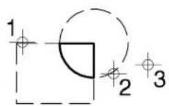
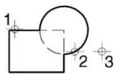
To construct a complex shape from the difference between elements
-
Select the Create Region tool.
-
Set Method to Difference.
If any elements are selected, they are de-selected.
-
Identify the base element (the element to be subtracted from).
-
Identify the element(s) to subtract from the element that was identified in step 3. ^3
-
Accept the last element.
Method set to Difference.
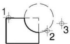
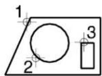
To construct a complex shape by "flood fill"
-
(Optional) — Select the bounding elements.
-
Select the Create Region tool.
-
Set Method to Flood.
-
(Optional) — If you want the complex shape to include any closed elements that are inside the area enclosed by the bounding elements, turn on Locate Interior Shapes.
-
Enter a data point in the area enclosed by the bounding elements.
-
Accept the complex shape.
Method set to Flood. Keep Original is off.
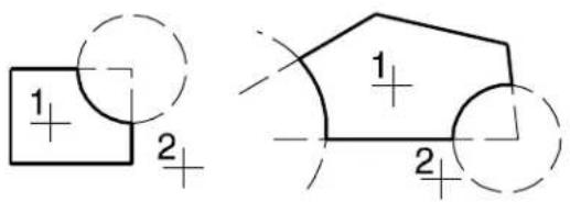
text_image
1 + 2 + 1 + 2
You can use a selection set to choose the bounding elements of a flood fill. This lets you choose the elements that will be considered in the calculations.
Key-in: CREATE REGION [DIFFERENCE | FLOOD | INTERSECTION | UNION ]
Add to Graphic Group

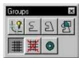
Used to do the following:
- Create a graphic group.
- Add elements to an existing graphic group.
- Combine two or more existing graphic groups into a single graphic group.
You can use selection sets to select multiple elements to include in a graphic group.
To create a graphic group or add elements to a graphic group
-
Select the Add to Graphic Group tool.
-
Identify the first element.
If the element is not in a graphic group, a new graphic group is created.
If the element is in a graphic group, all elements subsequently identified are added to that graphic group.
-
Identify another element(s) to add to the graphic group.
-
Accept the graphic group.
Using a selection set to add elements to a graphic group
- Use the Element Selection tool to select the required elements.
- Select the Add to Graphic Group tool.
- Accept the graphic group.
Key-in: GROUP ADD
Drop from Graphic Group

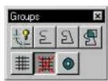
Used to do the following:
- Remove (drop) an element(s) from a graphic group.
- Drop the grouped status of the entire graphic group; that is,
break up the graphic group into its components.
You can use selection sets to choose multiple elements to drop from the graphic group.
To remove an element(s) from a graphic group
- In the Settings menu's Locks submenu, turn off Graphic Group.
- Select the Drop from Graphic Group tool.
- Identify the element(s) to be removed from the graphic group.
- Accept the drop.
To use a selection set to remove elements from a graphic group
- In the Settings menu's Locks submenu, turn off Graphic Group.
- Use the Element Selection tool, or the Power Selector tool to select the required elements.
- Select the Drop from Graphic Group tool.
- Accept to drop the selected elements.
Tobreakupanentiregraphicgroup
- In the Settings menu's Locks submenu, turn on Graphic Group.
- Select the Drop from Graphic Group tool.
- Identify a member of the graphic group.
- Accept the drop.
Key-in: GROUP DROP
Group Holes

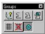
Used to identify a solid element and the hole elements to be associated with the solid.
The solid and its associated hole(s) can be shapes, ellipses, and/or complex shapes that are in the same plane. Holes are not patterned and appear “transparent” in rendered views.
To group a solid and a hole(s)
- Select the Group Holes tool.
- Identify the solid element.
- Identify the hole element(s) to associate with the solid.
- Accept the last element.
- Reset.
The solid and holes are consolidated into a group (orphan cell). The area attribute (solid or hole) of each element is set appropriately. The holes immediately follow the solid in the group definition.
Group Holes. The block is identified as the solid and the c i r c l e a n d hexagon are holes (Top view).
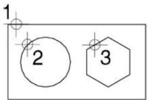
text_image
1 2 3Key-in: GROUP HOLES

One way to create a 3D solid of extrusion or revolution with a hole(s) in it is to use the Group Holes tool to associate the planar boundary element with its associated holes before generating the solid with the Extrude tool (see page 8-101) or the Construct Revolution tool (see page 8-107).
Rendered view of an extruded solid generated from the group created in the illustration.
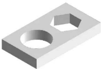
natural_image
3D rendering of a rectangular mechanical part with two circular holes and a hexagonal hole (no text or symbols)Using Multi-lines
A multi-line element consists of up to 16 independently-defined lines and optional end caps and joints.
Multi-lines
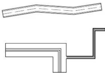
natural_image
Pure technical line drawing of two mechanical components without any text or symbols-
The active multi-line definition specifies the form of multi-lines placed with the Place Multi-line tool. The component lines can be varying distances apart. Each component line can have its own level, color, line style, and line weight.
• You can define and save multi-lines as styles in settings files. -
You can easily "clean up" intersections in multi-lines and modify individual multi-line components using the tools in the Multi-line Joints tool box (see page 7-32).
- You can associate multi-lines to other elements (see "Associating multi-lines" on page 7-51).
General Procedure — To define a multi-line
- From the Element menu, choose Multi-lines.
The Multi-lines dialog box opens.
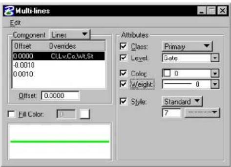
text_image
Multi-lines Edit Component Lines Offset Overides 0.0000 CLLvCo.Wt.St -0.0010 0.0010 Offset: 0.0000 Fill Color: 1 Attributes Class: Primay Level: Gate Color: 0 Weight: 0 Style: Standard 7The controls show the settings that constitute the active multi-line definition. The defined multi-line (if there is one) is shown graphically in the dialog box's lower left corner.
The Component option menu controls which controls display in the dialog box.
- Add any desired component lines to the multi-line definition. See "To add a line to a multi-line definition" on page 7-28.
- Adjust each new component line's offset. See "To adjust a component line's offset" on page 7-28.
- Give the component lines any desired attributes (class, level, color, line weight, and line style) to override the active element attributes when the multi-line is placed. See "To give a component line attributes that override the active element attributes" on page 7-28.
-
Add any desired color fill to the areas between component lines. See "To add color fill to a multi-line definition" on page 7-29.
-
Delete any unwanted lines from the multi-line definition. See "To delete a component line from a multi-line definition" on page 7-29.
- Define a start cap for the multi-line. See "To define a start cap for a multi-line" on page 7-29.
- Define an end cap for the multi-line. See "To define an end cap for a multi-line" on page 7-30.
- Adjust the settings for joints (a line optionally displayed at vertices in the multi-line). See "To define multi-line joints" on page 7-30.
- Save the new multi-line definition as a settings group component. See "Settings Files" in the Administrator Guide.
To add a line to a multi-line definition
- From the Component option menu, in the Multi-lines dialog box, choose Lines.
- From the dialog box's Edit menu, choose Insert.
A new line displays in the lines list box. It has no offset value and no attribute override settings.
To adjust a component line's offset
- From the Co mponent option menu in the Multi-lines dialog box, choose Lines.
- Select the desired line in the list box.
- Key in a positive or negative offset value (in working units) in the Offset field.
To give a component line attributes that override the active element attributes
- From the Component option menu in the Multi-lines dialog box, choose Lines.
- Select the desired line in the list box.
- To give the selected line attributes of class, level, color, line weight, and line style (to override the active element attributes), turn on the desired controls to the right and adjust the settings.
The controls work the same way as the controls in the
Element Attributes dialog box.
To add color fill to a multi-line definition
- In the Multi-lines dialog box, turn on Fill Color.
- From the adjacent color palette, choose the desired fill color.
To delete a component line from a multi-line definition
- From the Component option menu in the Multi-lines dialog box, choose Lines.
- Select the desired line in the list box.
- From the dialog box's Edit menu, choose Delete.
To define a start cap for a multi-line
- From the Component option menu in the Multi-lines dialog box, choose Start Cap.
The controls for defining a start cap display. A graphic representation of the start cap definition displays in the lower left corner of the dialog box.
- Turn on one, two, or all of the start cap types:
Line — a straight line across the end of the multi-line.
Outer Arc — a single arc bridging the two outermost lines.
Inner Arcs — arcs between each component line and the component line nearest it on each side.
- To give the start cap attributes of class, level, color, line weight, and line style (to override the active element attributes), turn on the desired controls to the right and adjust the settings.
The controls work the same way as the controls in the Element Attributes dialog box.
To define an end cap for a multi-line
- From the Component option menu in the Multi-lines dialog box, choose End Cap.
The controls for defining an end cap are displayed. A graphic representation of the end cap definition is displayed in the lower left corner of the dialog box.
- Turn on one, two, or all of the end cap types:
Line — a straight line across the end of the multi-line.
Outer Arc — a single arc bridging the two outermost lines.
Inner Arcs — arcs between each component line and the component line nearest it on each side.
- To give the end cap attributes of class, level, color, line weight, and line style (to override the active element attributes), turn on the desired controls to the right and adjust the settings.
The controls work the same way as the controls in the Element Attributes dialog box.
To define multi-line joints
- From the Component option menu in the Multi-lines dialog box, choose Joints.
The controls for defining multi-line joints display. A graphic representation of the joint displays in the lower left corner of the dialog box (if Display Joints is on).
-
To have joints display, turn on Display Joints.
-
To give the joints attributes of class, level, color, line weight, and line style (to override the active element attributes), turn on the desired controls to the right and adjust the settings.
The controls work the same way as the controls in the Element Attributes dialog box.
To retrieve a multi-line definition stored as a style and make it active
- From the Settings menu, choose Manage.
The Select Settings window opens. The drawing settings groups in the open settings file are listed in the Group list box.
- From the dialog box's Style menu, choose Multi-Line.
The Select Multi-line Style dialog box opens.
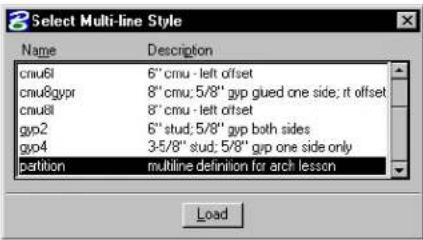
text_image
Select Multi-line Style Name Description cnu6l 6" cmu - left offset cnu8gyp 8" cmu; 5/8" gyp glued one side; it offset cnu8l 8" cmu - left offset gyp2 6" stud; 5/8" gyp both sides gyp4 3/5/8" stud; 5/8" gip one side only partition multiline definition for arch lesson Load-
In the list box, select the desired style.
-
Click Load.
The active multi-line definition is set as specified in the style definition.
Dropping multi-lines
You can "drop" a multi-line. That is, break it up into component lines, line strings, and so on. This can be done to let you manipulate the multi-line's components individually.

To drop all multi-lines in the fence contents, key if FENCE DROP MLINE.
To "drop" a multi-line
- In the Drop tool box, select the Drop Multi-line tool (see page 4-86).

- Identify the multi-line.
- Accept the drop.
Alternative method — To “drop” a multi-line
- Select the multi-line.
- In the Drop tool box, select the Drop Multi-line tool.

You also can use the Drop Element tool, with Multi-lines turned on, to drop a multi-line back to its component elements.
Multi-line Joints tool box
The tools in the Multi-line Joints tool box are used to construct joints at multi-line intersections, construct cuts (breaks) in multi-lines, and modify multi-line components. Multi-lines are placed with the Place Multi-line tool (see page 2-24) in the Linear Elements tool box.
| To | Select in the Multi-line Joints tool box |
| Construct a closed cross joint. |  Construct Closed Cross Joint(see page 7-35) Construct Closed Cross Joint(see page 7-35) |
| Construct an open cross joint. |  Construct Open Cross Joint(see page 7-36) Construct Open Cross Joint(see page 7-36) |
| Construct a merged cross joint. |  Construct Merged Cross Joint(see page 7-37) Construct Merged Cross Joint(see page 7-37) |
| Cut (break) a component line in a multi-line segment. |  Cut Single Component Line(see page 7-38) Cut Single Component Line(see page 7-38) |
| Cut (break) all component lines in a multi-line segment. |  Cut All Component Lines (see page 7-39) Cut All Component Lines (see page 7-39) |
| Construct a closed tee joint. |  Construct Closed Tee Joint (see page 7-40) Construct Closed Tee Joint (see page 7-40) |
| Construct an open tee joint. |  Construct Open Tee Joint (see page 7-41) Construct Open Tee Joint (see page 7-41) |
| Construct a merged tee joint. |  Construct Merged Tee Joint(see page 7-42) Construct Merged Tee Joint(see page 7-42) |
| To | Select in the Multi-line Join tool box |
| Construct a corner joint. |  Construct Corner Joint (see page 7-43) Construct Corner Joint (see page 7-43) |
| Remove a break in a multi-line. |  Uncut Component Lines (see page 7-44) Uncut Component Lines (see page 7-44) |
| Partially delete a multi-line without losing previously created breaks. |  Multi-line Partial Delete (see page 7-45) Multi-line Partial Delete (see page 7-45) |
| Move a multi-line's work line or one of its component lines. |  Move Multi-line Profile (see page 7-47) Move Multi-line Profile (see page 7-47) |
| Change the end cap of a multi-line. |  Edit Multi-line Cap (see page 7-49) Edit Multi-line Cap (see page 7-49) |
Key-in: DIALOG TOOLBOX JOINTS [OFF | ON | TOGGLE]
Construct Closed Cross Joint

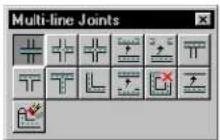
Used to construct a closed cross joint between two multi-lines.
To construct a closed cross joint
- Select the Construct Closed Cross Joint tool.
- Identify the multi-line to break.
- Identify the other multi-line.
- Accept the joint.
Construct Closed Cross Joint
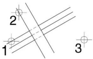
text_image
1 2 3Key-in: JOIN CROSS CLOSED
Construct Open Cross Joint

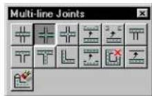
Used to construct an open cross joint between two multi-lines. All component lines of the first identified multi-line are broken. Only the outside component lines of the second are broken.
To construct an open cross joint
- Select the Construct Open Cross Joint tool.
- Identify the first multi-line.
- Identify the second multi-line.
- Accept the joint.
Construct Open
Cross Joint
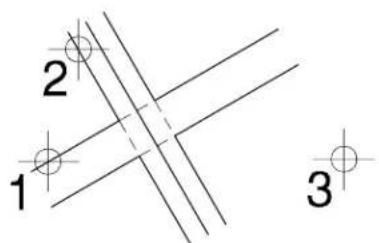
text_image
1 2 3Key-in: JOIN CROSS OPEN
Construct Merged Cross Joint

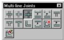
Used to construct a merged cross joint between two multi-lines.
To construct a merged cross joint
- Select the Construct Merged Cross Joint tool.
- Identify one multi-line.
- Identify the other multi-line.
- Accept the joint.
Construct Merged Cross Joint
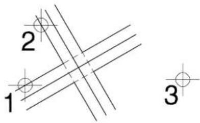
text_image
1 2 3Key-in: JOIN CROSS MERGE
Cut Single Component Line

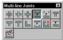
Used to cut (break) a component line in a multi-line segment.
To cut a single component line
- Select the Cut Single Component Line tool.
- Identify the component line at the point where cutting will begin.
- Enter a data point to define the end of the cut.
Cut Single Component Line
text_image
1 2Key-in: CUT SINGLE

To re-connect component lines that have been cut, use the Uncut Component Lines tool (see page 7-44).
Cut All Component Lines

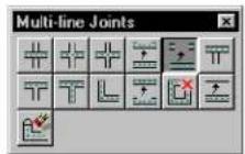
Used to cut (break) all component lines in a multi-line segment. The cuts are made on an axis perpendicular to the identified component line.
To cut all component lines
- Select the Cut All Component Lines tool.
- Identify any component line at the point where cutting will begin.
- Enter a data point to define the end of the cut.
Cut All Component Lines
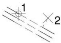
Key-in: CUT ALL

To re-connect component lines that have been cut, use the Uncut Component Lines tool (see page 7-44).

When a multi-line is cut, it remains a single element. To delete part of a multi-line, use the Multi-line Partial Delete tool (see page 7-45).
Construct Closed Tee Joint

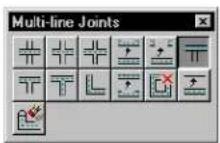
Used to extend or shorten a multi-line to its intersection with another multi-line and construct a closed tee joint.
To construct a closed tee joint
- Select the Construct Closed Tee Joint tool.
- Identify the multi-line to extend or shorten.
- Identify the multi-line to which the first multi-line will be extended or shortened.
- Accept the joint.
Construct Closed Tee Joint
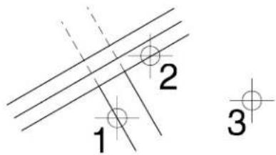
text_image
1 2 3Key-in: JOIN TEE CLOSED
When a multi-line is shortened, the part of the multi-line identified is kept.
7-40 MicroStation User Guide
Construct Open Tee Joint

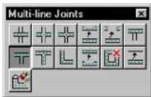
Used to extend or shorten a multi-line to its intersection with another multi-line and construct an open tee joint.
To construct an open tee joint
- Select the Construct Open Tee Joint tool.
- Identify the multi-line to extend or shorten.
- Identify the multi-line to which the first multi-line will be extended or shortened.
- Accept the joint.
Construct Open Tee Joint
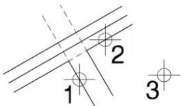
text_image
1 2 3MicroStation User Guide 7-41
Key-in: JOIN TEE OPEN
Construct Merged Tee Joint

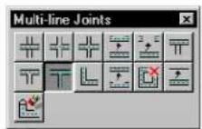
Used to extend or shorten a multi-line to its intersection with another multi-line and construct a merged tee joint.
To construct a merged tee joint
- Select the Construct Merged Tee Joint tool.
- Identify the multi-line to extend or shorten.
- Identify the multi-line to which the first multi-line will be extended or shortened.
- Accept the joint.
Construct Merged
Tee Joint
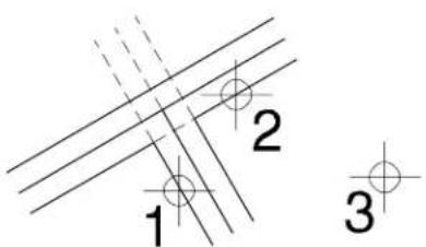
text_image
1 2 37-42 MicroStation User Guide
Key-in: JOIN TEE MERGE

When a multi-line is shortened, the part of the multi-line identified is kept.
Construct Corner Joint

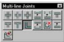
Used to extend or shorten two multi-lines to their intersection and construct a corner joint.
To construct a corner joint
- Select the Construct Corner Joint tool.
- Identify one multi-line.
- Identify the other multi-line.
- Accept the joint.
Construct Corner Joint
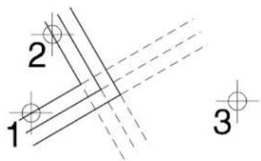
text_image
1 2 3Key-in: JOIN CORNER

When a multi-line is shortened, the part of the multi-line identified is kept.
Uncut Component Lines

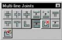
Used to remove a break in a multi-line, when the multi-line was broken with one of the cut or join tools.
To uncut a single component line
- Select the Uncut Component Lines tool.
- Identify one end of the break.
- Accept the modification.
Uncutting one component line
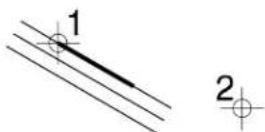
To uncut all component lines
- Select the multi-line(s).
- Select the Uncut Component Lines tool.
Key-in: UNCUT
Multi-line Partial Delete

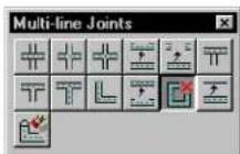
Used to partially delete a multi-line without losing any previously created breaks.
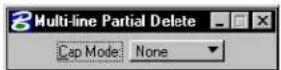
| Tool Setting | Effect |
| Cap Mode | Determines whether end caps are created and how they are defined: None-No caps are created. The end cap angle will be 90^ . Effect is same as Cut All Component Lines tool (see page 7-39). Current-Uses the start cap and end cap definitions of the identified multi-line. Active-Uses the active multi-line definition. Joint-Uses the identified multi-line's joint definition instead of end cap definition. Ensures end cap will always be 90^ . |
To delete part of a multi-line
- Select the Multi-line Partial Delete tool.
- Identify the multi-line at one end of the part to delete.
- For an open multi-line, enter a data point to define the other end of the part to delete.
or For a closed multi-line, enter a data point to define the direction in which to delete. Then enter another data point to define the other end of the part to delete.
Key-in: MLINE PARTIAL DELETE
Move Multi-line Profile

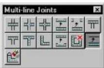
Used to do the following:
- Move an individual component line of a multi-line.
- Reposition the work line of a multi-line without moving its component lines.
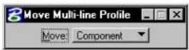
| Tool Setting | Effect |
| Move Determines the tool's operation:Workline—Move the identified multi-line's work line without moving its component lines.Component—Move a single component line of the identified multi-line. | |
To move a multi-line's work line
-
Select the Move Multi-line Profile tool.
-
In the Tool Settings window, set Move to Workline.
-
Identify the multi-line.
A dashed dynamic line displays. This represents the work line.
- Enter a data point to reposition the work line.
With typical usage, the appearance of the component lines is unchanged. However, if you move the dynamic work line far enough to cause segments to reverse direction it becomes impossible to preserve the appearance of the multi-line.
When this occurs, the entire multi-line dynamically displays showing its new configuration. Entering a data point when this occurs modifies the entire multi-line.
To move one of a multi-line's component lines
-
Select the Move Multi-line Profile tool.
-
In the Tool Settings window, set Move to Component.
-
Identify t he component line.
The identified component line dynamically highlights. Should you move the highlighted component line in a manner that affects other components of the multi-line (end caps, for instance), these components also highlight and dynamically change with the identified component line.
- Enter a dat a point to reposition the component line.
Key-in: MLINE EDIT PROFILE
Edit Multi-line Cap

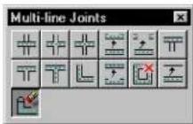
Used to change the end cap of a multi-line.
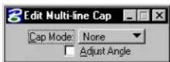
| Tool Setting | Effect |
| Cap Mode | Sets type of end cap: None—Removes any end caps. The end cap angle will be 90^ . Effect is same as Cut All Component Lines tool (see page 7-39). Current—Does not change the end cap. Enabled only when Adjust Angle is turned on. Active—Uses the active multi-line definition for the end cap. Joint—Uses the multi-line’s joint definition instead of its cap definitions. Ensures end cap will always be 90^ . |
| Adjust Angle | If on, lets you adjust the angle of the end cap. |
To change a multi-line's end cap
- Select the Edit Multi-line Cap tool.
- Identify the multi-line nearest the end cap to be modified.
- If Adjust Angle is off, accept the modified cap. or If Adjust Angle is on, enter a data point to adjust the angle of the end cap.
Key-in: MLINE EDIT CAP

Using AccuDraw with the Adjust Angle option makes it easier to make the end cap perpendicular to the rest of the multi-line.
Associating Elements
Under most circumstances, elements are static and, when an element is placed in a design, its position is defined simply by the design plane coordinates on which it lies. It retains that position in the design plane until you move it with an element manipulation tool.
One exception to this rule is association, in which an element's position in the design plane is defined in relation to another element. When that other element is moved, the associated element moves with it. For example, dimension elements can be associated with the elements whose dimensions they display. These dimensions update when the dimensions of the elements, with which they are associated, change.
Elements that can be associated with other elements
The types of elements that can be associated with other elements are dimensions, multi-lines, normal cells and shared cells. The association is made when the dimension, multi-line, or cell is placed. The procedures for associating cells and multi-lines are covered here. For more information about associative dimensions, see “Associating Dimensions With Elements” in the Guide to Generating Drawings.
Associating cells
When a cell is associated with another element, the cell's origin is associated with a point on the other element.
To associate a shared cell with another element
- From the Element menu, choose Cells.
The Cell Library dialog box opens. - If using a shared cell, turn on Use Shared Cells.
- In the list box, select the desired cell.
- In the Active Cells section, click the Placement button.
- In the Cells tool box, select the Place Active Cell tool. (In the Main tool frame, Place Active Cell is the default "representative" of the Cells tool box.)
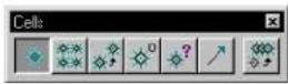
The prompt in the status bar is "Place Active Cell."
-
In the tool settings Placement Options (extended) section, turn on Association Lock.
-
Snap a tentative point to the element to which the cell is to be associated.
-
Enter a data point to accept placement and association of the Active Cell.
Associating multi-lines
When a multi-line is associated with another element, one or more vertices of the multi-line are associated with points on another element (or elements).
To associate a multi-line with another element
- In the Settings menu's Locks sub menu, or in the tool settings for the Place Multi-line tool, turn on Association (Lock).
- In the Linear Elements tool box, select the Place Multi-line tool.

Vertices of the multi-line that are not associated with other elements can be placed in the normal way (as if placing a line string). When you are ready to place a vertex associated with another element, continue with step 3.
- Snap to a tentative point on the element to which the multi-line's vertex is to be associated.
- Enter a data point to accept placement of the vertex of the multi-line and its association with the other element.
- Continue placing vertices of the multi-line or Reset to complete the multi-line.
The vertices of a multi-line can further be associated with vertices of other multi-lines.
Isometric Drawing
Isometric drawing is a technique used to represent 3D relationships in a 2D design. There are special tools to quickly and accurately place isometric representations of blocks and circles, and you can configure the screen pointer to make the job even easier. However, such drawings are not 3D models; they are strictly illustrative.
To set the Isometric (drawing) Plane
- From the Settings menu's Locks submenu, choose Full. The Locks dialog box opens.
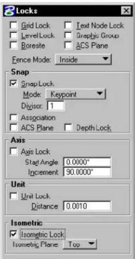
text_image
Locks Grid Lock Text Node Lock LevelLock Graphic Group Boresite ACS Plane Fence Mode: Inside Snap Snap Lock Mode: Keypoint Divisor: 1 Association ACS Plane Depth Lock Axis Axis Lock Staff Angle 0.0000° Increment 90.0000° Unit Unit Lock Distance 0.0010 Isometric Isometric Lock Isometric Plane Top- From the Isometric Plane option menu, choose Top, Left, Right, or All.
√ You can also set the Isometric Plane in the Tool Settings window for the Place Isometric Block and Place Isometric Circle tools.
To force each data point to lie on the Isometric Plane
- In the Settings menu's Locks submenu, turn on Isometric (Lock). When a linear element is placed, it "snaps" to the Isometric Plane.
Line string placed with Isometric Lock on and Isometra Plane set to Top. Note how the lines are constrained.
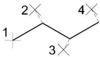
text_image
1 2 3 4To configure the pointer for isometric drawing
- From the Workspace menu, choose Preferences.
The Preferences dialog box opens. - In the Preferences dialog box's Category list box, select Input.
- From the Pointer Type option menu, choose Isometric.
The pointer's cross hairs will indicate graphically the Isometric Plane in which elements are placed. -
(Optional) — From the Pointer Size option menu, choose Full View.
The pointer's cross hairs will extend to the edges of the screen, facilitating alignment of new elements with elements in the same isometric plane. -
Click OK.
Isometric tool box
The tools in the Isometric tool box are used to represent 3D relationships in a 2D design.
| To | Select in the Isometric tool box |
| Place a shape that represents a rectangle projected from the isometric drawing plane. |  Place Isometric Block(see page 7-55) Place Isometric Block(see page 7-55) |
| Place an ellipsethatrepresents a circle projected from the isometric drawing plane. |  Place Isometric Circle(see page 7-57) Place Isometric Circle(see page 7-57) |
Key-in: DIALOG TOOLBOX ISOMETRIC [OFF | ON | TOGGLE]

To create 3D models, draw in 3D. See "3D Design and Modeling" on page 8-75.
Place Isometric Block


Used to place a planar shape representing a rectangle projected from the isometric drawing plane.
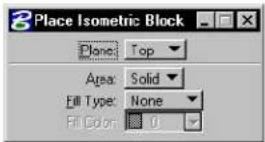
| Tool Setting | Effect |
| Plane | Defines angles of isometric axes:Top—30° and 150°Left—90° and 150°Right—30° and 90° |
| Area | Sets the type of isometric block created.Solid—The block is placed as a solid element (can be hatched/patterned).Hole—The block is placed as a hole element (cannot be hatched/patterned). |
| Fill Type | Sets the active Fill Type.None—No fillOpaque—Filled with Active ColorOutlined—Filled with Fill Color (outline of block takes the Active Color) |
| Fill Color | Sets the color with which the shape is filled.· If Fill Type is Opaque, the Active Color.· If Fill Type is Outlined, the fill color can be different from the Active Color. |
To place an "isometric" block
- Select the Place Isometric Block tool.
- Enter a data point to define one corner.
- Enter a data point to define the corner that is diagonal from the first.
Place Isometric Block with Isometric Plane set to Top (Left) (b), and Right (c).
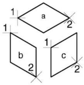
text_image
1 a 2 1 b 2 1 c 2Key-in: PLACE BLOCK ISOMETRIC
Place Isometric Circle


Used to place a planar ellipse representing a circle projected from the isometric drawing plane.
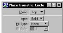
| Tool Setting | Effect |
| Plane | Defines angles of isometric axes:Top—30° and 150°Left—90° and 150°Right—30° and 90° |
| Area | Sets the type of isometric circle created.Solid—The circle is placed as a solid element (can be hatched/patterned).Hole—The circle is placed as a hole element (cannot be hatched/patterned). |
| Fill Type | Sets the active Fill Type.None—No fillOpaque—Filled with Active ColorOutlined—Filled with Fill Color (outline of circle takes the Active Color) |
| Fill Color | Sets the color with which the “isometric circle” is filled• If Fill Type is Opaque, the Active Color.• If Fill Type is Outlined, the fill color can be different from the Active Color. |
To place an "isometric" circle
- Select the Place Isometric Circle tool.
- Enter a data point to define the center.
- Enter a second data point on the circumference.
Place Isometric Circle with the Isometric Plae set to Top (a), Left (b), and Right (c).
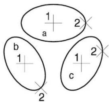
text_image
1 a 2 b 1 2 c 2Key-in: PLACE CIRCLE ISOMETRIC
Using Curves
With manual drafting tools, you can draw a point curve (a curve through a series of points) with a French curve. MicroStation has, in effect, a variety of mathematical French curves for placing curves on the basis of data points in the design plane, including point curves and NURBS (non-uniform rational B-splines).
Composite curves (see page 7-66) actually can consist of a combination of line segments, arcs, and Bézier curves.
You can draw curves without any understanding of the mathematics behind them, or you can create curves based on sophisticated mathematical formulas (see “Creating any conceivable curve” on page 7-67).
The easiest way to become familiar with curve placement tools is to enter a series of data points or a line string, then construct different curves based on those elements. With B-splines, you can adjust the settings as you watch the curve update, then accept the curve when it has the correct shape.
Point curves
Point curves are based on a relatively simple mathematical formula — there are no settings that control the curve's shape. As you place a point curve, it is dynamically displayed as you enter data points. Of course, you can place active points or other elements to snap to as you place the point curve, and you can enter the data points using AccuDraw.

Point curves are placed with the Place Point or Stream Curve tool (see page 2-29) in the Linear Elements tool box.
Point curves
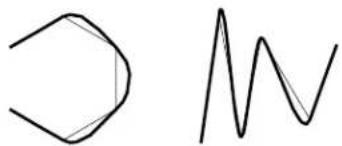
chemical
Simple molecular structure diagram showing a cyclohexane ring and a wavy line representing a resonance or bondB-spline curves
A B-spline curve is more complex mathematically than a point curve. A B-spline curve's shape is determined by the number and location of its poles, which are represented as vertices of the curve's control polygon and its order.
B-spline curve and its control polygon.
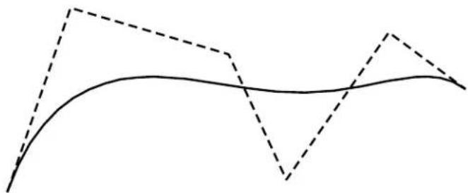
natural_image
Abstract line drawing with solid and dashed lines forming a wavy pattern (no text or symbols)B-spline curves are drawn with the Place B-spline Curve tool (see page 7-75) in the Create Curves tool box as well as several special-purpose 2D B-spline tools (see page 7-66).

You can place a B-spline curve by entering data points or construct it by identifying a line string or shape — this is determined by choosing Placement or Construction, respectively, from the Define By option menu in the Tool Settings window.
Methods by which the curve is calculated
Unlike point curves, there are a number of Methods, which can be chosen from the Method option menu, for calculating the final curve that results.
| Method Data | points or vertices of element define |
| Define Poles Vertices of control polygon. | |
| Through Points | Points on the curve. |
| Least Squares by Tolerance and Least Squares by Number | A set of points that the curve approximates or is “fit” to. |
| Catmull-Rom A | set of points that is closely approximated. |
These illustrations show the different types of B-spline curves constructed from the same line string.
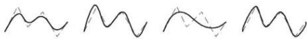
natural_image
Four abstract wavy line patterns with no text or symbolsB-spline curves constructed based on a line string. Method set to, from left: Define Poles, Through Points, Least Squares, Catmull-Rom.
Least Squares by Tolerance
Curves created with this method are approximated, based on the points used to define the curve and the Tolerance setting. The maximum deviation of the input points from the curve is controlled by the Tolerance setting.
Least Squares by Number
This Method lets you adjust the number of poles in the control polygon.
If the number of poles is lower than the number of data points or vertices, the curve is fit using the least squares method.
Generally, the more poles in the control polygon, the better the curve will fit a regular shape. In the following illustration, the line string on which the B-splines were based is shown as a solid line. The control polygons are displayed, as they are in MicroStation, as dashed lines.
B-spline curves
by Least
Squares based
onthesameline
string: three,
four, and five poles.
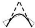
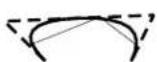
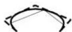
Catmull-Rom
The Catmull-Rom curve is popular with aircraft and ship hull designers — it passes directly through the data points or vertices on which it is based, as do point curves and B-splines Through Points. In general, the approximation is more accurate than with other methods.
Catmull-Rom curves avoid these problems:
- Point curves are flat between the first and second data points as well as between the next-to-last and last data points.
- With very irregular shapes, B-spline curves Through Points can develop unwanted loops.
Line string in shape of square as the basis for B-spline: Through Points (left) and Catmull-Rom (right).
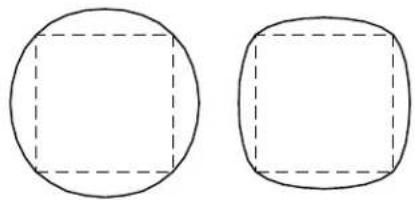
natural_image
Two geometric shapes: a circle with a square cutout and an oval with a rounded square cutout (no text or symbols)B-spline curve attributes
B-spline curve settings are set in the B-spline and 3D dialog box, which is opened by choosing B-spline and 3D from the Element menu.
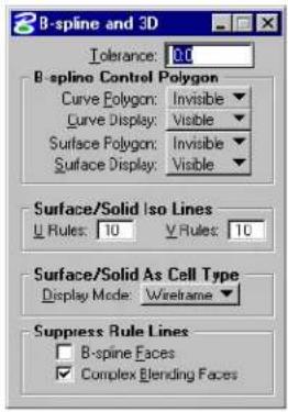
text_image
B-spline and 3D Tolerance: 0.0 B-spline Control Polygon Curve Polygon: Invisible Curve Display: Visible Surface Polygon: Invisible Surface Display: Visible Surface/Solid Iso Lines Rules: 10 Rules: 10 Surface/Solid As Cell Type Display Mode: Wireframe Suppress Rule Lines B-spline Faces Complex Blending FacesChanges to the attributes of existing B-spline curves are carried out with the Modify Curves tool box's Change to Active Curve Settings tool (see page 7-110).
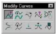
Display of the curve or control polygon
You can turn on or off the display of either the control polygon or curve.
Order
In practical terms, a B-spline curve's order defines the curve's distance from the control polygon's poles. The greater the order, the further the curve can lie from the poles of its control polygon. A high-order curve is "freer" than a low-order curve.
The limit to a curve's order is the number of poles: You cannot place a B-spline curve with a greater order than the number of poles.
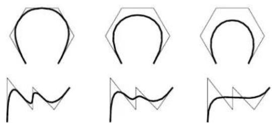
natural_image
Six abstract line drawings with geometric shapes and wavy lines, no text or symbols presentB-spline curves (Method set to Define Poles and Define By set to Construction). The Order increases from left to right. In these cases, the line strings are congruent with the control polygons.
Closure
A closed B-spline starts and ends at the same point, and encloses an area.
A closed B-spline can also be periodic, which means that all derivatives of the curve (less than order -1) are continuous through the points. In other words, a periodic B-spline passes “smoothly” through the point at which its ends are joined, without a kink in the curve.
In a design, a B-spline whose ends do not meet can be called “open.” Mathematically, however, an open B-spline starts at its first pole and ends at its last pole, and the ends need not meet. Setting the Closure tool setting to Open results in mathematically open B-spline curves.
You can use the Change to Active Curve Settings tool (see page 7-110) to change a periodic B-spline's definition in the model to be a mathematically open B-spline without changing its shape. This is helpful when the DGN file is to be transferred to a package that does not support periodic B-splines.
Special-purpose 2D B-spline tools
These tools in the Curves tool box are used to place the following special types of 2D B-spline curves.
The Place Conic tool (see page 7-91) is used to place a conic section — a hyperbola, parabola, or partial ellipse.

The Place Spiral tool (see page 7-94) is used to place a transitional spiral — this is most commonly used for highway design.

The Construct Interpolation by Arcs tool (see page 7-89) is used to place a complex chain of arcs that passes through a given set of points.

Composite curves
The Place Composite Curve tool (see page 7-85) in the Curves tool box lets you place a complex element that can contain line segments, arcs, and a special type of B-spline curve, a Bézier curve.

Bézier curves
A Bézier curve is a B-spline curve with the same number of poles as its order. Thus, a fourth-order B-spline with four poles is a fourth-order Bézier curve. These are very popular as they allow control of a curve's starting and ending position as well as the tangents at those positions.
Composite curve compris- ing a line, a n arc, a Bézier curve, another line, and an arc.
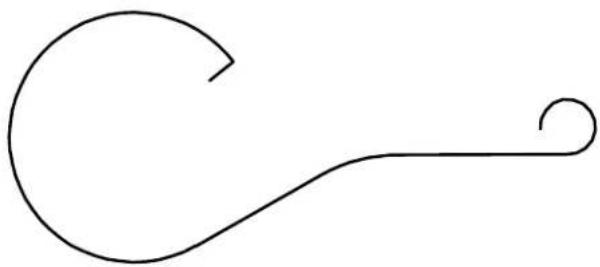
natural_image
Simple line drawing of a curved hook or handle with a looped end (no text or symbols)The handles that appear when placing a Bézier curve with the Place Composite Curve tool (see page 7-85) control the tangents at the ends of the curve segment. The line defined by the first and second poles is the initial tangent direction, and the line defined by the third and fourth poles is the final tangent direction. The length of the handles controls the size of the tangent at each end. (A tangent is a vector so it has direction and magnitude.)
Creating any conceivable curve

The Curve Calculator tool (see page 7-101) lets you create any conceivable planar curve, based on a mathematical formula.
• A pre-defined curve can be selected from a library and placed in the design.
- New curves can be defined and added to the supplied libraries. This is similar to programming a programmable calculator.

Equations that are dimmed in the list box are locked. Modifying
them can corrupt the curve's formula and should only be done if you understand how the curve is defined and wish to modify its underlying definition. See "To define a curve's formula" on page 7-70.

To unlock an equation, key in FORMULA UNLOCK [number], where [number] denotes the position of the equation in the list of locked equations.
General Procedure — To place a pre-defined curve
- In the Curves tool box, select the Curve Calculator tool.
The Curve Calculator dialog box opens.
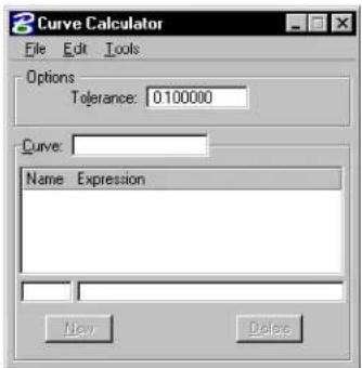
text_image
Curve Calculator File Edit Tools Options Tolerance: 0.100000 Curve: Name Expression New Delete- From the File menu in the Curve Calculator dialog box, choose Open File.
The Resource File to Open dialog box opens.
- Select a curve library file and click the OK button.
The Resource File to Open dialog box closes and the Open Curve
Resource dialog box opens for the selected resource.
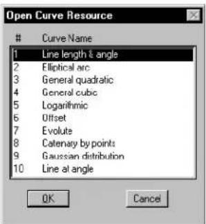
text_image
Open Curve ResourceCurve Name
1 Line length & angle 2 Elliptical arc 3 General quadratic 4 General cubic 5 Logarithmic 6 Offset 7 Evolute 8 Catenary by points 9 Gaussian distribution 10 Line at angle OK Cancel- Select a curve in the list box and click OK.
The Open Curve Resource dialog box closes and the selected curve's defining equations are listed in the Curve Calculator dialog box. - Edit values in the equation that defines the curve. See "To edit values in the equation that defines a curve" on page 7-69.
- From the Tools menu in the Curve Calculator dialog box, choose Place Parametric Curve.
- Enter a data point to define the curve's origin.
The curve is defined relative to the coordinate system of the view in which this data point is entered.
To select another curve from the resource
- From the File menu in the Curve Calculator dialog box, choose Open Curve.
The Open Curve Resource dialog box opens.
- Select a curve in the list box and click OK.
To edit values in the equation that defines a curve
- In the Curve Calculator dialog box, select a row in the list box. or
Key in the variable's name in its text item.
The variable and value appear in the text items below the list box.
- Keyinanewvalue.
General Procedure — To define a curve's formula
- In the Curves tool box, select the Curve Calculator tool.
The Curve Calculator dialog box opens. - In the Curve field, key in the curve's name.
- Define the equations.
- Lock the equations that, if modified, would corrupt the definition. See "To lock an equation" on page 7-70 for details.
- Place a curve to test the equation.
- Save the equation.

Some mathematical knowledge is needed to define a new curve. A curve is defined by the parametric equations for the x, y, and z coordinates of the curve. These formulas give the value of the articular coordinate as a parameter “t” that is between zero and one (0.0 < t < 1.0). This is the standard parametric form of a curve described in mathematical text books.

Variable names are limited to 8 characters and the right side of the equation is limited to 40 characters. There is also a limit of 25 formulas to define a curve.
To lock an equation
- In the Curve Calculator dialog box, select the equation in the list box and key in FORMULA LOCK.
Key in FORMULA LOCK [number].
number is the equation's number (the count starts at zero).
The locked equation is grayed-out in the list box and cannot be modified.
Examples
A=sinusoid=with=an=amplitude=of=5=and=wave=length=of=10=can be defined=with=the=following=equations:
| Formula Syntax | |
| x(t)===10u(t) | x=== 10^* u |
| y(t)===5sin(u(t)) | y(t)=== 5^* sin(u) |
| u(t)===2t | u(t)=== 2^* pi*t |
The=third=equation=is=necessary=since="t" = must=be=between=zero=and one=and=we=want=an=entire=period=of=the=sine=wave,=from=0-2
Auxiliary=functions=such=as=this=can=be=defined.=By=using=two auxiliary=variable-value=equations=for=the=amplitude=and=wave length=a=more=flexible=definition=results.
$$ \begin{array}{l} \mathrm{x} = = = \mathrm{wl} ^ {} \mathrm{u} \ \mathrm{y} = = = \text { amp } ^ {} \sin (\mathrm{u}) \ \mathrm{u} = 2 ^ {} \mathrm{pi} ^ {} \mathrm{t} \ \mathrm{amp} = = = 5 \ \mathrm{wl} = = = 1 0 \ \end{array} $$
This=definition=could=be=used=to=place=sine=waves=of=any=amplitude and=wave=length=by=modifying=the=last=two=equations.=It=is=clear, however,=that=the=first=three=equations=should=not=be=modified,=since doing=that=would=corrupt=the=sine=wave's=definition.=To=prevent this-you=can=lock=the=first=three=formulas.=These=equations=would then=be=dimmed=in=the=list=box=and=the=end-user=would=not=be=able to=harm=them.=The=status=of=an=equation,=locked—or=unlocked, is=saved=with=the=equation=in=the=library=file;it=is=set=using=the Formula=Lock/Unlock=key-in=described=above.
Dimensionality
Curves=can=be defined=in=2=or=3=dimensions:if=no=z=formula=is=present the=z=value=defaults=to=0,=thereby=creating=a=planar=curve.
Function format
The formulas defining the x, y, and z coordinates of the curve can use trigonometric, hyperbolic, logarithmic, exponential, or power functions. The format for such functions is as follows:
| Function | Returns |
| sin (value) | sine of value ^1 |
| cos (value \) | cosine of value ^a |
| tan (value) | tangent of va lue ^a |
| asin (value) | arc sine of value ^a |
| acos (value) | arc cosine of value ^a |
| atan (value) | arc tangent of value ^a |
| atan2 (y, x) | arctan(y)/x ^a |
| sinh (value) | hyperbolic sine of value |
| cosh (value) | hyperbolic cosine of value |
| tanh (value) | hyperbolic tangent of value |
| asinh (value) | inverse hyperbolic sine of value |
| exp (value) | e ^value |
| ldexp (x,p) | 2xp |
| log (value) | natural logarithm of value |
| log10 (value) | base 10 logarithm of value |
| ldexp (x, y) | xy |
| sqrt (value) | square root of value |
1 Depends on global angle units setting

Curve Calculator also understands standard C operators.
Deriving a curve from an existing curve
A curve can be defined from a set of formulas alone or can be derived from formulas and an existing curve (the root curve). If a curve is
7-72 MicroStation User Guide
derived, then these values can be referenced in the equations.
These values are derived from the Frenet frame of the root curve and are updated depending on the value of “t,” the curve parameter. All these values begin with an underscore.
| Value Description | |
| _rx | x coordinate of root curve's position |
| _ry | y coordinate of root curve's position |
| _rz | z coordinate of root curve's position |
| _tx | x coordinate of root curve's tangent |
| _ty | y coordinate of root curve's tangent |
| _tz z coordinate | of root curve's tangent |
| _mx | x coordinate of root curve's normal |
| _my y coordinate | of root curve's normal |
| _mz | z coordinate of root curve's normal |
| _bx | x c o o r d i n farotcurve's binormal |
| _by | y coordinate of root curve's binormal |
| _bz | z coordinate of root curve's binormal |
| _kappa | curvature of root curve |
| _tau | torsion of root curve |
The following constants can be referenced in equations:
| Value Description | |
| pi | π |
| e e | |
Create Curves tool box
The Create Curves tool box has tools that are used to draw curves and extract iso-parametric lines from a solid or B-spline surface.
| To | Select in the Curves tool b |
| Place a B-spline curve |  Place B-spline Curve (see page 7-75) Place B-spline Curve (see page 7-75) |
| Create a B-spline curve that passes through a set of points while maintaining user-defined tangent direct at those points. |  Create Curve by Tangents (see page 7-82) Create Curve by Tangents (see page 7-82) |
| Place a composite curve, which can have line strings, arcs, or Bézier curves as components. |  Place Composite Curve (see page 7-85) Place Composite Curve (see page 7-85) |
| Place or construct a complex chain of arcs that passes through a given set of points. |  Construct Interpolation by Art tool (see page 7-89) Construct Interpolation by Art tool (see page 7-89) |
| Place a parabola, hyperbola, or partial ellipse. |  Place Conic (see page 7-91) Place Conic (see page 7-91) |
| Place a clothoid or Archimedes or logarithmic spiral. |  Place Spiral (see page 7-94) Place Spiral (see page 7-94) |
| Place a helix in a 3D design. |  Place Helix (see page 7-95) Place Helix (see page 7-95) |
| Construct a B-spline curve that is the same distance from the identified element at all points. |  Offset Curve see page 7-97) Offset Curve see page 7-97) |
| To | Select in the Curves tool box |
| Extract a B-spline curve(s) from asolidoraB-splinesur |  Extract Iso-parametric Lines(see page 7-99) Extract Iso-parametric Lines(see page 7-99) |
| Place a curve by defining its mathematical formula. |  Curve Calculator tool (see page 7-101) Curve Calculator tool (see page 7-101) |
Key-in: DIALOG TOOLBOX CURVECREATE[OFF | ON | TOGGLE]

To construct a curve along the intersection of two 3D elements, use the Construct Trim tool (see page 8-184) in the Modify Surfaces tool box.

B-spline curve and surface settings are set in the B-spline and 3D dialog box, which is opened by choosing B-spline and 3D from the Element menu.
Place B-spline Curve

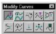
Used to place a B-spline curve. For general information about curve placement, see "Using Curves" on page 7-59.
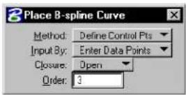
| Method | Description Illustration | |
| Define Control P[oin]ts | The=poles=(vertices)=of the=control=polygon=are defined=by=data=points=or the=vertices=of=the=selected line=string=or=shape.=The number=of=poles=must=be greater than o requ the=order. If=Closure=is Open,=the=curve=is=placed between=the=first=and=last points=or=vertices. | 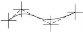 alto alto |
| Through Points | The=curve=passes=through the=points=defined=by the=data=points=or=the vertices=of=the=identified line=string=or=shape=and is=interpoited=at=each point.=The=curve=is=cubic (Order=4)=with=continuous second=derivatives=——this minimizes=the=curvature. | 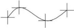 |
| L[east]. Square[s] By Tol[er-ance] | The=curve=is=approximated based=on=the=points=defined by=the=data=points=or=the vertices=of=the=identified line=string=or=shape.=The maximum=deviation=of=the input=points=from=the=curve is=adjustable=using=the Tolerance=setting. After the=approximation=curve is=created,=the=maximum deviation=and=the=mean deviation=display=in=the status field. | 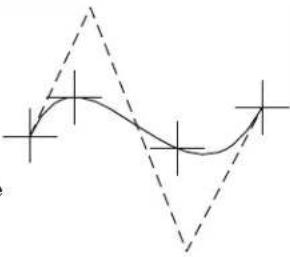 |
| L[cast]-Square[s]ByNum[ber] | The sum of the square the distances from the data points or the vertices of the selected line string or shape to corresponding points on the curve is minimized.The control polygon has the active number of Poles.If the number of data points or vertices is the same as the number of Poles, the curve passes through all the data points or vertices,If Closure is set to Open, the curve begins and ends at the first last data points, respectively.If Closure is set to Closed, the curve approximates all data points or vertices and need not pass through any of them, unless there are the same number as the number of Poles.If the maximum error exceeds the Tolerance ^1 , t h e m a x i m u m e r r o r displays in status bar. | 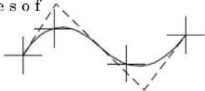 |
| Cat-mull-Rom | Fourth-order=(cubic)NURBS=curve=that=isinterpolated.=Extrapoles=are=added=to=closelyresemble=the=shape=definedby=the=data=points=enteredusing=this=formula:=Number=of=Poles==3=×=(Data=Points-1)+1 | 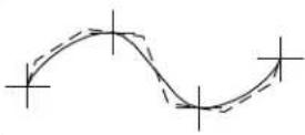 |
1 The Tolerance is set in the B-splines dialog box (Element > B-splines).
| Tool Setting | Effect |
| Method | Sets=the=manner=in=which=the=curve=is=generated(see=large=table=above). |
| Input By | Sets=the=manner=in=which=the=inputpoints=are=located.Enter Data Points—The=curve=is=placed=by=entering data=points.=The=curve=dynamically=updates=while new points are entered or when the pointer is moved.Pick Line String—The=curve=is=constructed=based=on the=vertices=of=an=identified=line=string=or=complex chain=(results=in=open=B-spline)=or=shape=or=complex shape=(results=in=closed=B-spline). |
| Closure | Sets=whether=the=curve=is=Open=or=Closed. Not available=if=Method=is=Catmull-Rom. |
| Order | (Method set to Define Control Pts. or L-Square By Num=only)=Sets=the=order=of=the=equation that=defines=the=curve=(2-15). |
| Poles | (Method=set=to=L-Square=By=Num=only)=Sets the=number=of=poles=(3-5000). |
| To le r an | c (Method set to L-Square By Tol. only) Sets the fitting or approximation tolerance. The distance from any one of the input data points to the curve is less than this value. The distance is computed by projecting a point to the curve. |
| End Tangent | (Method set to Through Points or L-Square By Tol and Closure set to Open only) Sets the manner in which the curve's tangency to adjacent elements is controlled.Automatic—default tangent directions are automatically computed.Both—starting and ending tangent directions are defined graphically.Start Tangent—starting tangent direction is defined graphically.End Tangent—ending tangent direction is defined graphically. |
| Through End Points | (Method set to L-Square By Tol only) Sets the manner in which the curve's beginning and ending points are located.If On, the curve passes through the first and the last input points. Otherwise, the curve's endpoints are computed based on the Tolerance setting. |
▶ ToplaceaB-splinecurvebyenteringdatapoints
- Select the Place B-spline Curve tool.
- In the tool settings window, set Input By to Enter Data Points.
- Enter a data point to define the curve's beginning.
- Enter a series of data points.
| Method Each | data point defines |
| Define Control Pts. | One of the control polygon's poles. |
| Through Points or Catmull-Rom | A point through which the curve must pass. |
| L-Square By Tol or L-Square By Num | One of a set of points that the curve must approximate. |
-
If Closure is set to Open, enter a data point to define the curve's end.
-
Reset.
The curve is generated unless Method is set to Through Points or L-Square By Tol and Closure is set to Open. In this case, continue with step 7.
-
If End Tangent is set to Start Tangent, End Tangent, or Both, enter a data point to define the starting or ending tangent direction.
-
If End Tangent is set to Both, enter a data point to define the ending tangent direction
To construct a B-spline curve by identifying an element
- Select the Place B-spline Curve tool.
- In the tool settings window, set Input By to Pick Line String.
- Identify a line string or complex chain to construct an open curve. or
Identify a shape or complex shape to construct a closed curve.
| Method Each | vertex defines |
| Define Control Pts. | One of the control polygon's poles. |
| Through Points or Catmull-Rom | A point through which the curve must pass. |
| L-Square By TolorL-Square By Num | One of a set of points that the curve must approximate. |
4. Accept.
The curve is generated unless Method is set to Through Points or L-Square By Tol and Closure is set to Open. In this case, continue with step 5.
-
If End Tangent is set to Start Tangent, End Tangent, or Both, enter a data point to define the starting or ending tangent direction.
-
If End Tangent is set to Both, enter a data point to define the ending tangent direction.
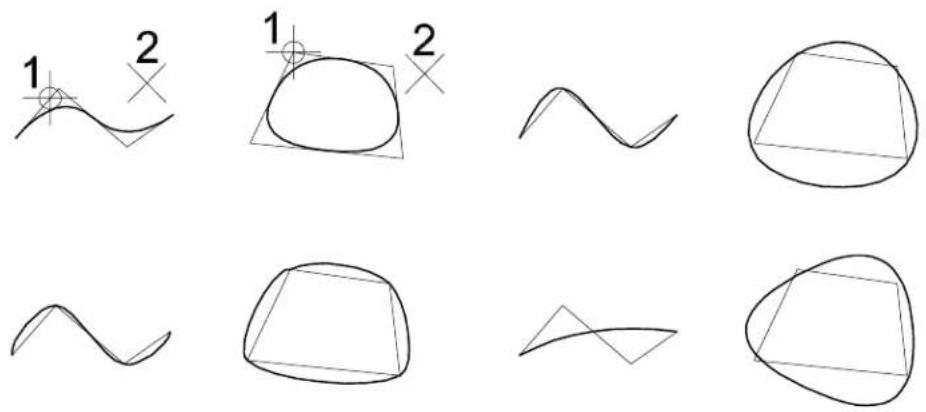
Top Left: Define Control Pts.; Top Right: Through Points; Bottom Left: Catmull-Rom, Bottom Right: L-Square by Num. B-spline curves constructed by identifying a line string or shape. The same curves could be placed by entering data points at the same position as the vertices. In these examples, the Order is 3, and for Least Squares only, the number of Poles is also 3.
Key-in: [CONSTRUCT | PLACE] BSPLINE CURVE (CATMULLROM | LEASTSQUARES | POINTS | POLES)
Create Curve by Tangents

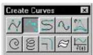
Used to create a B-spline curve that passes through a set of points while maintaining user-defined tangent directions at those
points. You can define points and tangent directions interactively using data points or by identifying elements. In the latter case, the curve passes through the starting points of the identified elements and uses directions of the elements as tangent inputs. The curve may be either quadratic or cubic.
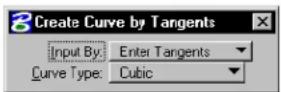
| Tool Setting | Effect |
| Input By | Sets the manner in which the input points are located.Enter Tangents—graphically define a series of vectorsPick Elements—identify existing elements. |
| Curve Type | Sets the curve fitting algorithm:Cubic—cubic (order 4)Quadratic—quadratic (order 3) |
To create a B-spline curve that passes through a set of data points with interactively specified tangent directions
- Select the Create Curve by Tangents tool.
- In the tool settings window, set Input By to Enter Tangents.
- Enter a data point to define the curve's starting point.
- Enter a data point to define the tangent direction at the defined starting point.
- Enter a data point to define the next point through which the curve will pass.
- Enter a data point to define the tangent direction at the point defined in the previous step.
- For each additional point through which the curve will
pass, repeat steps 5 and 6 (above).
- Reset to generate the curve.
As data points are entered, defining each curve point 1 and tangent direction (2), graphics dynamically display the point(s) and the tangent direction(s). After placing the required data points, entering a reset generates the curve.
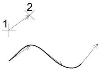
text_image
1 2To create a B-spline curve that passes through the vertices of existing elements and whose tangent directions correspond to the elements' directions
- Select the Create Curve by Tangents tool.
- In the tool settings window, set Input By to Pick Elements.
- Identify an element.
- Identify another element(s).
- Accept.
The curve is generated. It passes through the endpoints of the identified elements, and its tangent directions correspond to the elements' directions.
Identify the elements (1, 2, 3) from which the curve is to be generated. Accept (4) to generate a curve passing through the end points of the selected elements, with its tangent directions corresponding to the elements' directions.
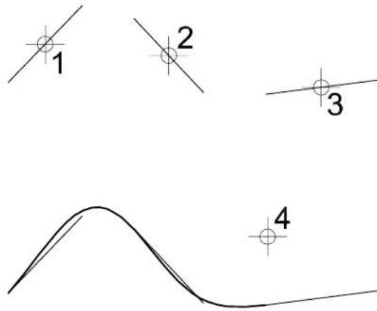
text_image
1 2 3 4Place Composite Curve

Used to place a composite curve, which can have line strings, arcs, or Bézier curves (fourth order B-spline curves with four poles) as components. If all components are line segments and there are fewer than 5000 vertices, a line string or shape is placed in the design; otherwise a complex chain or complex shape is placed.
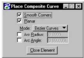
text_image
Place Composite Curve ✓ Smooth Corners ✓ Planar Mode: Bezier Curves Arc Radius: 0.0000 Arc Angle: 0.0000 Close Element| Tool Setting | Effect |
| Smooth Corners | If on, intersections of arcs and Bézier curves are smooth. |
| Planar | If on and the active design file is 3D, the composite curve is forced to lie on one plane. |
| Mode Sets | the type of component that is placed (see step 4 below). |
| Arc Radius | (Arc by Edge or Arc by Center only) If on, sets the arc radius. |
| Arc Angle | (Arc by Edge or Arc by Center only) If on, sets the arc sweep angle. |
| Close Element | Creates a shape by connecting the first point with the last point. |
To place a composite curve
- Select the Place Composite Curve tool.
- From the tool settings window's Mode option menu, choose the component.
- If this is the first component in the composite curve, enter a data point to define the origin.
- Enter data points to place the component (follow the
prompts in the status bar).
| Mode Enter data points to | Similar to | |
| Arcs By Edge | Define point on arc.Define arc endpoint. | Place Arc (see page 2-67) |
| Arcs By Center | Define center (defines radius, unless Radius is on).Define sweep angle (unless Arc Angle is on). | Place Arc (see page 2-67) |
| Bézier Curves Define first anchor point.Define first direction point (define tangency).Define second anchor point (endpoint).Define second direction point. | None | |
| Line Segments Define endpoints of segments. | Place SmartLine (see page 2-17) | |
- To place more of the same component, return to step 4.
or
To choose a different component, return to step 2.
or
To complete an open composite curve, Reset.
or
To complete a closed composite curve, click the Close Element
button, or key in CLOSE ELEMENT.
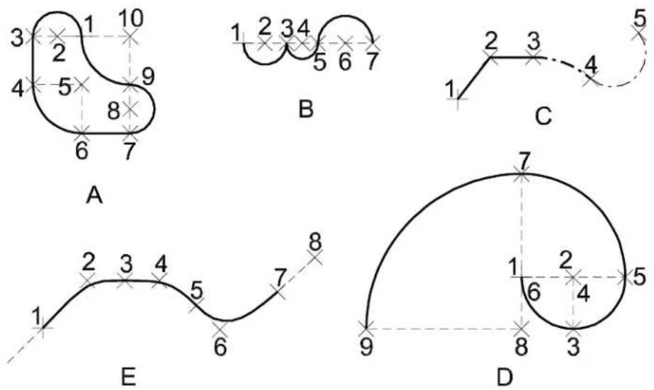
Place Composite Curve. Clockwise from top left:
A: Smooth Corners is on. At first, Mode is Arcs By Center. After data point 3, Mode is set to Line Segments, back to Arcs By Center after datapoint 4, and soon. The figure is closed by entering a data point at the same location as the origin or by clicking Close Element.
B: Mode is Arcs by Center. For first two arcs, Smooth Corners is off. After data point 5, Smooth Corners is on.
C: Mode is initially Line segments. After data point 3, the Mode is changed to Arcs By Edge and the Line Style is also changed. After data point 4, the Line Weight is changed.
D: The Fibonacci curve is placed with Mode set to Arcs by Center, Smooth Curves on, and Arc Angle set. tTh00 Arc Radius is 1 for first two arcs and is changed to 2 and 3 after data points 5 and 7, respectively.
E: Mode is Bézier curve. The odd-numbered data points define anchor points; the even numbered ones define direction (tangency) points. A Reset was entered after data point 8 to complete the curve.
Key-in: PLACE COMPOSITE

To combine contiguous open elements of any type into a complex chain (open) or complex shape (closed), use the Create Complex Chain tool (see page 7-12) or Create Complex Shape tool (see page 7-15) in the Groups tool box.
Construct Interpolation by Arcs

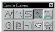
Used to place or construct a complex chain of arcs that passes through a given set of points. The arcs are joined smoothly — that is, they have tangent continuities. The given points can either be specified as a line string or shape element or entered interactively.
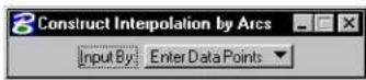
| Tool Setting | Effect |
| Input By | Sets how the complex chain is defined.Enter Data Points—The complex chain is placed by entering data points.Pick Line String—The complex chain is constructed based on the vertices of an identified line string or shape. |
To place an arc interpolation by entering data points
- Select the Construct Interpolation by Arcs tool.
- In the tool settings window, set Input By to Enter Data Points.
- Enter a data point to define the beginning of the interpolation.
- Continue to enter data points to define other interpolation points.
- Reset to complete the definition.
To construct an arc interpolation by identifying an element
- Select the Construct Interpolation by Arcs tool.
- In the tool settings window, set Input By to Pick Line String.
- Identify a line string or shape from which to construct the interpolation.
- Accept the construction.
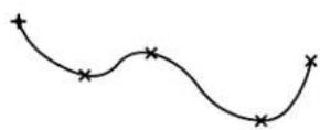
Key-in: CONSTRUCT ARCS INTERPOLATION
Place Conic

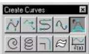
Used to place a conic section — a hyperbola, parabola, or partial ellipse — as a third-order uniform rational B-spline curve with three poles.
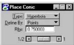
1 To construct a parabolic fillet to two elements, use the Construct Parabolic Fillet tool.
2 To place a partial ellipse as an arc element, use the Place Half Ellipse tool or Place Quarter Ellipse tool in the Arcs tool box.
| Tool Setting | Effect |
| Type | Sets whether the conic section is a Hyperbola, Parabola, ^1 or Partial Ellipse. ^2 |
| Define By | Sets the point defined in step 4 of the procedure below.Points—a point on the element is defined.Tangents—the intersection of the tangent lines is defined. |
| Rho | The=range=setting=is=variable=for=Hyperbola and=Partial=Ellipses=only=and=its=value depends=on=the=Type:=If=Hyperbola, =0.5=<ρ<1.0=If=Parabola, ρ=0.5.=If=Partial=Ellipse, =0.0=<ρ<0..5. |
To place a conic section
- Select=the=PlaceCoGooitool
- Enter=addatapoint=theDefine=onepoidpoint.
- Enter a data point to define the other endpoint.
- Enter = a final kdtat a point.
If Define By is set to Points, it defines the shoulder point.
If=Define=By=is=set=to=Tangent,=it=defines the intersection of=the=tangent=lines.
Place=Conic.
Left: By
Points;=Right
By=Tangent.
Double-
dotted=curves
are=partial
ellipses=(0.0
<<0.5) ,
solid=curves
are=parabolas
( = ±b0, 5) , and
single-dotted
curves=are
hyperbolas
(0.5=<ρ<1.0).
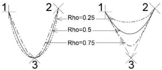
text_image
1 2 Rho=0.25 Rho=0.5 Rho=0.75 3 1 2 3Key-in: PLACE CONIC
Place Spiral

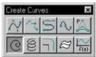
Used to place a transitional spiral as a B-spline curve.
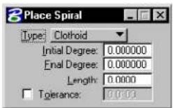
| Tool Setting | Effect |
| Type Sets | the spiral's mathematical definition.Clothoid—Used to create a smooth transition between arcs that have different radii so that there is no abrupt change of curvature. Used in highway design.Archimedes—The radius changes linearly based on the angle.Logarithmic—The radius changes exponentially based on the angle. |
| Initial Degree | (Type set to Clothoid only) Sets the degree of curvature at the origin. |
| Final Degree | (Type set to Clothoid only) Sets the degree of curvature at the spiral's endpoint. |
| Length | (Type set to Clothoid only) Sets the spiral's length. |
| Initial Radius | (Type set to Archimedes or Logarithmic only) Sets the radius at the origin. |
| Final Radius | (Type set to Archimedes or Logarithmic only) Sets the radius at the spiral's endpoint. |
| Angle | (Type set to Archimedes or Logarithmic only) Sets the sweep angle. |
| To le r - ance | (Type set to Clothoid or Logarithmic only) Sets the tolerance. |
To place a spiral
- Select the Place Spiral tool.
- Enter a data point to define the spiral's origin.
- Enter a data point to define the tangent direction at the origin.
- Enter a data point to define the spiral's direction.
Key-in: PLACE SPIRAL
Place Helix

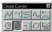
(3D only) Used to place a helix (3D B-spline curve).
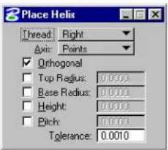
text_image
Place Helix Thread: Right Axis: Points Orthogonal Top Radius: 0.0001 Base Radius: 0.0001 Height: 0.0001 Pitch: 0.0001 Tolerance: 0.0010| Tool Setting | Effect |
| Thread Can be right or left. | |
| Axis Sets the direction of the helix's axis.Points—Lets you define the direction of the axis graphically.Screen X, Y, or Z—Sets the direction of the axis parallel to the Screen X, Y, or Z axis.Drawing X, Y, or Z—Sets the direction of the axis parallel to the Drawing, or DGN file's X, Y, or Z axis. | |
| Orthogonal | If on, the helix is orthogonal. |
| Top Radius | If on, sets the second radius (step 5 below). |
| Base Radius | If on, sets the first radius (step 3 below). |
| Height If on, sets the height (step 4 below). | |
| Pitch If on, sets the pitch. | |
| To le r an c e Sets the tolerance. | |
To place a helix
- Select the Place Helix tool.
- Enter a data point to define the Base end of the axis.
If all constraints are on and Axis is set to anything other than Points, the helix is displayed dynamically and you can
enter a data point to accept the helix.
- Enter a data point to define the beginning of the helix and the first (Base) radius.
- Enter a data point to define the other end of the axis.
- Enter a data point to define the second (Top) radius.
- Accept the helix.
Key-in: PLACE HELIX
Offset Curve

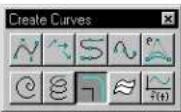
Used to construct an offset curve from an element (line, line string, multi-line, curve, arc, ellipse, shape, complex chain, or complex shape) — a B-spline curve that is the same distance from the identified element at all points.
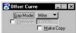
| Tool Setting | Effect |
| Gap Mode | Sets how “corners” are treated in the offset curve.Miter—Where necessary, straight sections that form sharp “corners” in the original element are extended to fill the gaps and maintain sharp “corners” in the offset curve.Round—Where necessary, rounding is added to fill the gaps where straight sections in the original element would leave gaps in the offset curve. |
| Distance | If on, sets the distance to offset. |
| Make Copy | If on, the element is copied and the original is not manipulated. |
To construct an offset curve
- Select the Offset Curve tool.
- Identify the element.
- Enter a data point.
| Distance This data point defines |
| Off Distance and direction. |
| On Direction only. |
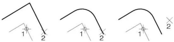
text_image
1 2 1 2 1 2Constructing an Offset Curve (Make Copy on). Left: Gap Fill Mode set to Miter and Distance off. Center: Gap Fill Mode set to Round and Distance off. Right: Gap Fill Mode set to Round and Distance On.
Key-in: CONSTRUCT OFFSET CURVE
Extract Iso-parametric Lines

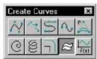
(3D only) Used to extract a B-spline curve(s) from a solid or a B-spline surface.
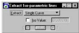
text_image
Extract Iso-parametric lines Extract: Single Curve Iso Value: 0.50000| Tool Setting | Effect |
| Extract | Sets the objective of the tool.Single Curve—Extract a curve that has a constant parametric u-value (iso-u curve) or constant parametric v-value (iso-v curve). The u-value or v-value is the specified Iso Value. The u-direction is the direction in which the data points that defined each row were entered; the v-direction is the direction in which the columns were defined.Multiple Curves—Extract a set of curves that are spaced evenly on the surface in both directions. |
| Iso Value | (Extract set to Single Curve only) If on, sets the iso value of the extracted curve. |
| Numbers U/V | (Extract set to Multiple Curves only) Sets the number of curves to extract from both parametric u- and v- directions. |
| Ignore Trim Region(s) | (Extract set to Multiple Curves only) If on, the curves are trimmed by the B-spline trim curves, if any. |
To construct a curve based on an iso-parametric line from a surface
- Select the Extract Iso-parametric Lines tool.
- In the tool settings, set Extract to Single Curve.
- Identify the surface.
As you move the pointer, an iso-u curve displays dynamically.
- Enter a data point to define the curve's position and create the iso-u curve.
or
Reset to display an iso-v curve.
As you move the pointer, an iso-v curve displays dynamically.
- Enter a data point to define the curve's position and create the iso-v curve (or Reset to create no curve).
(1) Identify the surface. (2) Enter a second data point to position the iso curve.
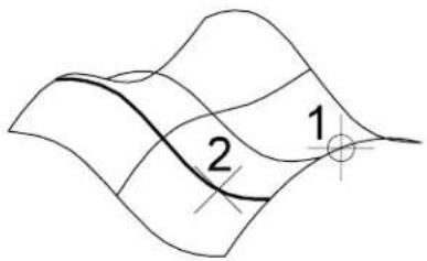
text_image
1 2To extract multiple curves from a surface
- Select the Extract Iso-parametric Lines tool.
- In the tool settings, set Extract to Multiple Curves.
- Identify the surface.
- Accept the surface.
The curves are generated.
Left: Original surface. Right: Surface with 10 extracted iso-parametric lines in both directions.
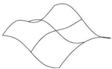
natural_image
Abstract wavy line drawing with no text or symbols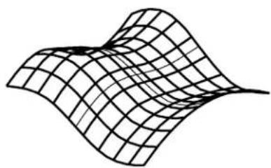
natural_image
Abstract wavy surface diagram with grid lines, no text or symbols presentKey-in: EXTRACT ISOLINE
Curve Calculator

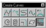
Opens the Curve Calculator dialog box (see page 7-103), which is used to place any conceivable planar curve as a NURBS, based on a mathematical formula, in either of the following ways:
• From a library of pre-defined curves.
- By defining a custom formula.
Trigonometric, hyperbolic, exponential, logarithmic, and power functions can be used to create sinusoids, spirals, catenaries, involutes, evolutes, and so on. For the creation procedures, see "Creating any conceivable curve" on page 7-67.
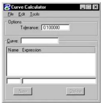
text_image
Curve Calculator File Edit Tools Options Tolerance: 0.100000 Curve: Name Expression New DeleteTo place a parametric curve
- With a curve definition loaded, from the Tools menu in the Curve Calculator dialog box, choose Place Parametric Curve.
- Enter a data point to define the curve's origin.
To place a parametric line string
- With a curve definition loaded, from the Tools menu in the Curve Calculator dialog box, choose Place Parametric Line String.
- Enter a data point to define the line string's origin.
To construct a curve defined by formulas and another curve
- With a curve definition loaded, from the Tools menu in the Curve
Calculator dialog box, choose Construct Parametric Curve.
- Identify the curve in the design.
- Accept the new curve.
To construct a line string defined by formulas and another curve
- With a curve definition loaded, from the Tools menu in the Curve Calculator dialog box, choose Construct Parametric Line String.
- Identify the existing curve.
- Accept the line string.
Key-in: MDL LOAD CURVCALC
Curve Calculator dialog box
Used to place any conceivable curve as a NURBs, based on a mathematical formula. Opens when the Curve Calculator tool is selected in the Curves tool box.
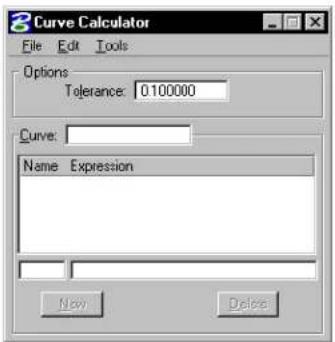
text_image
Curve Calculator File Edit Tools Options Tolerance: 0.100000 Curve: Name Expression New DeleteYou can set values in the equations that define the curve. The variable-value pairs can be edited as follows:
- Select a row in the list box. The variable and value appear in the text items below the list box.
- Enter a variable's name in its text item and press (Return).
- The key-in SET VALUE [variable] [new value] can be used to update a variable-value pair.
The dynamics reflect any changes in the variable-value pairs defining the curve if a placement tool is selected.

Formulas in black are variable-value pairs that can be edited. Formulas that are dimmed are locked and cannot be selected. These are the parametric equations of the curve and should not be changed unless you want to define a new curve (see "Defining a Curve's Formula" on page 7-70).

For example, the supplied curve definition "Elliptical arc" (in "curve.rsc") lets you enter values for the two radii that define the ellipse as well as the start and sweep angles.
Tolerance
Sets the tolerance.
Key-in: MDL LOAD CURVCALC
Key-in: ACTIVE TOLERANCE
Curve
Displays the name of the currently loaded curve. The list box below displays the Name and Expression values for variables associated with the displayed curve. You can enter new variables and values in the two text fields directly below this list box.
New
Activates when a new variable is added to the Name text field.
Delete
Activates when a variable is selected in the Name/Expression list box.
File > New File
Lets you remove a curve library and start a new curve library.
Key-in: MDL LOAD CURVCALC
Key-in: MENU NEWFILE
File > Open File
Opens the Resource file to Open dialog box, which is used to open a library of pre-defined curves.
Key-in: MDL LOAD CURVCALC
Key-in: MENU OPENFILE FILENAME

By default, looks for ".rsc" files in the directory pointed to by the MS_DATA configuration variable.
File > New Curve
Clears the current curve and values, to let you create a new curve definition.
Key-in: MDL LOAD CURVCALC
Key-in: MENU NEWCURVE
File > Open Curve
Opens the Open Curve Resource dialog box, which is used to select a curve from the open library of pre-defined curves.
Key-in: MDL LOAD CURVCALC
Key-in: MENU OPENCURVE CURVE NUMBER
File > Save
Saves the curve library file.
Key-in: MDL LOAD CURVCALC
Key-in: MENU SAVE
File > Save As...
Opens a dialog box which is used to create a new curve library file.
Key-in: MDL LOAD CURVCALC
Key-in: MENU SAVETO
Edit > Clear
Removes the listed curve from curve library. All equations are removed and the defaults are set for tolerance, units, angle, and mode.
Key-in: MDL LOAD CURVCALC
Key-in: MENU CLEAR
Edit > Duplicate
Lets you duplicate the currently selected curve, giving it a new name. This makes it easy to define a new curve from an old curve without having to re-type all the equations.
Key-in: MDL LOAD CURVCALC
Key-in: MENU DUPLICATE
Edit > Angles
Lets you set the Active Angle Units to either Degrees or Radians
Key-in: MDL LOAD CURVCALC
Key-in: ACTIVE ANGLES (DEGREES | RADIANS)
Edit > Mode
Sets the type of curve or linestring to create.
| Curve type | Specified Created using | |
| Defined=Completely=byequations | Place=Parametric=Curve,or=Place=ParametricLinestring | |
| Derived=By=equations=and=a root=curve | Construct=ParametricCurve,=or=ConstructParametric=Linestring | |
A=curve's=type=is=stored=in=the=library=file=so=that=the=appropriate create=commands=can=be=enabled=when=the=curve=is=loaded.
Key-in: MDL LOAD CURVCALC
Key-in: ACTIVE MODE [DEFINED | DERIVED]
Tools > Place Parametric Curve
(Edit => Mode=set=to=Defined=only)=Used=to=place=a=curve=that=is=defined by=listed=formulas=relative=to=a=view's=coordinate=system.
The=active=units,=active=angle,=and=Tolerance=are=set=in=the Curve=Calculator=dialog=box.
Key-in: MDL LOAD CURVCALC
Key-in: PLACE PARAMETRIC CURVE RELATIVE

To=place=a=curve=that=is=defined=by=listed=formulas=relative to=the=design=file=coordinate=system,=key=PLACE PARAMETRIC CURVE ABSOLUTE.
Tools > Place Parametric Line String
(Edit=>=Mode=set=to=Defined=only)=Used=to=place=a=line=string that=is=defined=by=listed=formulas=relative=to=a=view's=coordinate system.=The=vertices=are=evaluated=at—even=intervals=throughout the=domain=of=the=equations.=By=default,=11=vertices=are=calculated at=the=values=t===0.0,=0.1,=0.2,...,1.0.
The=active=units,=active=angle,=and=Tolerance=are=set=in=the Curve=Calculator=dialog=box.
Key-in: MDL LOAD CURVCALC
Key-in: PLACE PARAMETRIC LINESTRING RELATIVE NUMBER_OF_VERTICES

To=place=a=line=string=that=is-defined=by=listed=formulas=relative=to the=design=file=coordinate=system,=key=PLACE PARAMETRIC LINESTRING ABSOLUTE number_of_points.
Tools > Construct Parametric Curve
(Edit => Mode=set=to=Derived=only)=Used=to=place=a=curve=defined by=the=listed=formulas=and=a=curve=in=the=design.=Offsets=and evolutes=are=examples=of=such=curves.
The=active=units,=active=angle=units,=and=Tolerance=are=set in=the=Curve=Calculator=dialog=box.
Key-in: MDL LOAD CURVCALC
Key-in: CONSTRUCT PARAMETRIC CURVE
Tools > Construct Parametric Line String
(Edit => Mode=set=to=Derived=only)=Used=to=create=a=curve-defined=by=the listed=formulas=and=a=curve=in=the=design.=The=vertices=are=evaluated=at even=intervals=throughout=the=domain=of=the=equations.=By=default, 11=vertices=are=calculated=at=the=values=t===0.0,=0.1,=0.2,...,1.0.
The=active=units,=active=angle,=and=Tolerance=are=set=in=the Curve=Calculator=dialog=box.
Key-in: MDL LOAD CURVCALC
Key-in: CONSTRUCT PARAMETRIC LINESTRING
Modify Curves tool box
The Modify Curves tool box has tools that are used to modify curves.
| To | Select in the Modify Curves tool box |
| Change a B-spline curve's attributes to the active B-spline curve settings. |  Change to Active Curve Settings (see page 7-110) Change to Active Curve Settings (see page 7-110) |
| "Clean up" curves with large numbers of control points. |  Rebuild Curve (see page 7-112) Rebuild Curve (see page 7-112) |
| Extend a B-spline curve. |  Extend Curve (see page 7-114) Extend Curve (see page 7-114) |
| Reverse the direction of an open B-spline curve or change the start of a closed B-spline curve. |  Change Element Direction (see page 7-116) Change Element Direction (see page 7-116) |
| Convert an element to a B-spline curve with the same shape. |  Convert Element to B-spline (see page 7-117) Convert Element to B-spline (see page 7-117) |
| Construct a blend curve between two elements. |  Blend Curves (see page 7-119) Blend Curves (see page 7-119) |
| Convert a B-spline curve to lines, a line string, a stream curve, arcs or points. |  Drop B-spline Curve (see page 7-121) Drop B-spline Curve (see page 7-121) |
| Flatten or project MicroStation curve type elements. |  Flatten Curve (see page 7-123) Flatten Curve (see page 7-123) |
| Deform a curve with restrictions. |  Deform Curve (see page 7-126) Deform Curve (see page 7-126) |
| Graphically and numerically evaluate the attributes of a B-spline curve at given locations on the curve. |  Evaluate Curve (see page 7-127) Evaluate Curve (see page 7-127) |
Key-in: DIALOG TOOLBOX CURVEMODIFY[OFF | ON | TOGGLE]
Change to Active Curve Settings

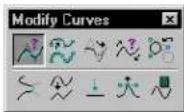
Used to change a B-spline curve's attributes to those of the active settings. Settings are changed only for the attribute(s) for which the tool setting(s) is on.
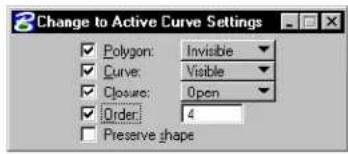
text_image
Change to Active Curve Settings Polygon: Invisible Curve: Visible Closure: Open Order: 4 Preserve shape| Tool Setting | Effect |
| Polygon If | on, sets whether the curve's control polygon is displayed:Invisible—the control polygon is not displayed.Visible—the control polygon is displayed. |
| Curve If on | sets whether the curve is displayed:Invisible—the curve is not displayed.Visible—the curve is displayed. |
| Closure | If on, sets the type of B-spline curve.Open—Converts a closed B-spline to an open curve.Closed—Converts an open B-spline to a closed curve. |
| Order If on | sets the curve's order. |
| Preserve Shape | (Order turned on only) If on, the curve's shape remains the same, even though the Order is changed. |
To change a B-spline curve's attributes (those that are on)
- Select the element(s).
- Select the Change to Active Curve Settings tool.
- In the tool settings, turn on and adjust the required settings.
- Accept the change.
Alternative method — To change a B-spline curve's attributes (those that are on)
- Select the Change to Active Curve Settings tool.
- In the tool settings, turn on and adjust the required settings.
- Identify the element(s).
- Accept the change.
Key-in: CHANGE CURVE
To set the active B-spline curve settings so they match those of a B-spline curve in the design, use the Match Curve Settings tool (see page 4-75) in the Match tool box.
Rebuild Curve

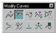
Used to "clean up" a B-spline curve that has a large number of control points (poles), like those sometimes created with the Offset Curve tool (see page 7-97) or imported from other systems.
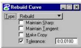
text_image
Rebuild Curve Type: Rebuild Maintain Sharp: Maintain Tangent: Make Copy Tolerance: 0.0.0100| Tool Setting | Effect |
| Type | Sets the type of curve that is created during the rebuilding.Rebuild—The curve is re-constructed, based on the given tolerance, to produce a “better” curve.Reduce Data—The number of control points is reduced, but the order of the curve is not changed.Reparameterize—Where a curve has all the knots concentrated in a certain region, such as at the beginning of the curve, it may be that the 0.5 knot is not near the middle of the curve. This option attempts to rebuild the curve such that the 0.5 knot corresponds, as near as possible, to the middle of the curve. |
| Maintain Sharp | (Type set to Rebuild only) If on, all the sharp corners of a curve will be maintained while the intermediate segments of the curve will be reconstructed. |
| Maintain Tangent | (Type set to Rebuild only) If on, a complex chain (with a line tangent to a B-spline curve) will be reconstructed such that the end result will still have the line and the B-spline tangent to each other, but the B-spline segment will be reconstructed. |
| Make Copy | (Type set to Rebuild or Reduce Data only) If on, the original curve is not deleted upon creation of the replacement curve. |
| Maintain End Tangents | (Type set to Reduce Data only) If on, the end tangent directions of the replacement curve are the same as those of the original. |
| To le r an | c Sets the maximum distance allowed between the replacement curve and the original curve. To make the replacement curve appear identical to the original, even though its complexity is reduced, experiment with different Tolerance values. |
To rebuild a B-spline curve
- Select the Rebuild Curve tool.
- In the tool settings, turn on and adjust the required settings.
- Identify the B-spline curve.
- Accept to rebuild.
Key-in: REBUILD CURVE

To check the number of control points in a B-spline curve, use the Analyze Element tool in the Primary Tools tool box or see Information in the Reference Guide.
Extend Curve

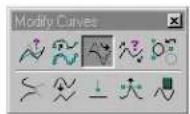
Used to extend an element (line, line string, arc, ellipse, complex chain or B-spline curve) by a certain scale.
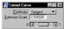
| Tool Setting | Effect |
| Continuity | Defines the smoothness of the extension. Position—The extension is a straight line. Tangent—The extension is tangent continuous. Curvature—The extension is curvature continuous. |
| Extension Scale | (Continuity set to Tangent or Curvature only) Scale relative to the length between the two poles of the curve at the end of the extension.1Must be greater than 0 and less than 1. |
1 More precisely: Length between first two poles of extension curve = Length between two poles of original curve x Extension Scale ÷ (1 - Extension Scale)
To extend an element by a certain scale
- Select the Extend Curve tool.
- Identify the holdment.
- Adjust tool setting as required.
- Accept the extension.
Key-in: EXTEND CURVE
Change Element Direction

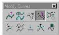
Used to reverse an element's (line, line string, arc, ellipse, complex chain, complex shape, curve, or B-spline curve) direction or change the start point (for closed elements).
An open element's direction when placed is from its start point (the first point defined) to its end point.
A closed element's direction when placed is counterclockwise.
An element's direction is significant when:
- It is labeled with the Label Line tool.
• A view is rotated to align with it.

| Tool Setting | Effect |
| Mode Sets | the mode in which the tool is used.Change Direction—Used to change the direction of an element.Change Starting Point—Used to change the starting point of an element. |
To reverse an element's direction
- Select the Change Element Direction tool.
- Set Mode to Change Direction.
- Identify the element.
The element is highlighted and an arrow showing its direction is displayed. - Accept.
The element's direction is reversed.
To move a closed element's start point
- Select the Change Element Direction tool.
- Set Modetang Starting Point.
- Identify the closed element.
The element is highlighted and an arrow showing its direction is displayed. - Identify the element's new start point.
- Accept.
Key-in: CHANGE DIRECTION
Convert Element to B-spline

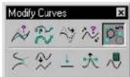
Used to convert an element (line, line string, arc, ellipse, complex chain, complex shape, surface of projection or revolution, or cone)
to a B-spline curve or surface with the same shape.
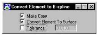
| Tool Setting | Effect |
| Make Copy | If on, a B-spline curve or surface, with the same shape as the identified element, is created.If off, the identified element is converted to a B-spline curve or surface. |
| Convert Element to Surface | If on, a closed element is converted to a B-spline surface rather than a closed B-spline curve. |
| To le r an | c (Convert Element to Surface on, only) If on, sets how accurately the element is converted to a surface. |
To convert an element to a B-spline
- Select the Convert Element to B-spline tool.
- Identify the element.
- Accept the new B-spline curve/surface.
Key-in: CONVERT BSPLINE
Blend Curves

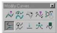
Used to construct a B-spline curve between two elements (lines, line strings, arcs, ellipses, complex chains, complex shapes, or B-spline curves) that consists of the trimmed original elements and a transition curve connecting them.
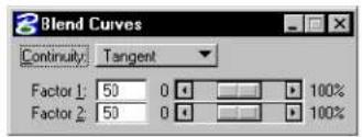
text_image
Blend Curves Continuity: Tangent Factor 1: 50 0 100% Factor 2: 50 0 100%| Tool Setting | Effect |
| Continuity | Sets number of control points between the blend points (identified in steps 2 and 4 below).Position—0 control points. A straight “line” is constructed between the blend points.Tangent—2 control points. In most cases, this is adequate.Curvature—4 control points. |
| Factor 1 | Magnitude of blend curve’s initial tangent. |
| Factor 2 | Magnitude of blend curve’s final tangent. |
To construct a blend between two elements
- Select the Blend Curves tool.
- Identify the first element at the blend's start point.
- Identify the end of the first element to trim.
- Identify the second element at the blend's end point.
- Identify the end of the second element to trim.
The blend curve displays dynamically.
-
(Optional) — Adjust the relative magnitudes of Factor 1 and Factor 2 to achieve the desired blend.
-
Accept the blend.
Blend Curves. Blending the line and arc shown at top left. Top right: Continuity is set to Position. Bottom: In both illustrations, Continuity is set to Tangent.
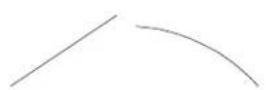
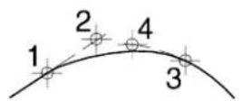
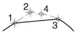
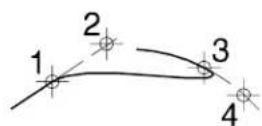
Key-in: BLEND CURVE
Drop B-spline Curve

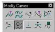
Used to convert a B-spline curve to lines, a line string, a stream curve, arcs or points.
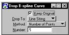
| Tool Setting | Effect |
| Keep Original | If on, the original B-spline curve is retained. |
| Drop To | Sets the element type to which the identified B-spline curve is converted.Line String—The B-spline curve is dropped to a line string.Lines—The B-spline curve is dropped to a number of connected lines.Stream Curve—The B-spline curve is dropped to a stream curve.Arcs—The B-spline curve is dropped to a number of connected arcs.Points—The B-spline curve is dropped to a number of points. |
| Method | Sets how the dropped element is constructed.Number of Points—The B-spline curve is evaluated evenly in the parameter space by the Number value.Equal Arc Length—The B-spline curve is evaluated evenly along the arc. Each segment has the same arc length, as defined by the value for Number.Equal Chord Length—The B-spline curve is evaluated at a given number of points such that the distance between each successive point is the same.Fixed Chord Length—The distance between each pair of successive points evaluated is the same as the chord length.Chord Height—The maximum chord height for all of the line segments is less than the Chord Height. |
| Number | Sets the:• Number of points when Method is set to Number of Points.• Arc length when Method is set to Equal Arc Length. |
| Chord Height | Sets the maximum chord height when Method is set to Chord Height. |
| Chord Length | Sets the chord length when Method is set to Fixed Chord Length. |
To drop a B-spline curve
- Select the Drop B-spline Curve tool.
-
Identify the B-spline curve.
-
Accept the drop.
Key-in: DROP CURVE
Flatten Curve

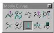
Used to flatten or project a MicroStation curve-type element, such as a line string, complex chain, complex shape, or B-spline curve, into a specified plane. This tool is designed to process digitized data or imported curves that are not currently planar but meant to be.
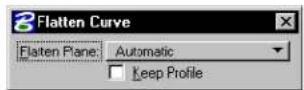
| Tool Setting | Effect |
| Flatten Plane | Sets the normal direction for the flatten plane.Automatic—computed by an averaging process based on the identified element.Closest Standard Plane—First, a normal direction is computed by the averaging process as is done in the Automatic case. This resulting plane is compared to the standard XY, YZ, and XZ planes to see which is closer. The closest is used as the flatten plane.Drawing XY Plane—parallel to the design cube's xy plane.Drawing XZ Plane—parallel to the design cube's xz plane.Drawing YZ Plane—parallel to the design cube's yz plane.View—parallel to the view.User Defined—defined by three data points. |
| Keep Profile | If on, the original curve is not deleted. |
To flatten or project an element
- Select the Flatten Curve tool.
- Identify the element to flatten or project.
- If Flatten Plane is set to Automatic or Closest Standard Plane, accept the element.
or If Flatten Plane is set to Drawing XY Plane, Drawing XZ Plane, or Drawing YZ Plane, enter a data point (base point) to define the location of the flatten plane.
or If Flatten Plane is set to View, enter a data point to define
the depth of the flatten plane.
or
If Flatten Plane is set to User Defined, enter a series of three data points (length, width, and height) to define the flatten plane.
With Keep Profile turned on, oh Flatten Plane set to Drawing XZ plane, identify the curve.
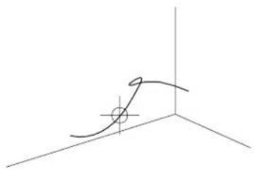
natural_image
Pure 3D coordinate axes with a curved line and a marked point (no text or symbols)Identify the location of the Drawing XZ plane, to generate the flattened curve.
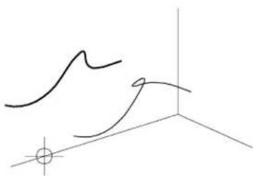
natural_image
Abstract line drawing with intersecting curves and a small circle at the origin (no text or symbols)Three-dimensional curve, shown with "flattened" arves aligned with the XY, XZ and YZ drawing planes.
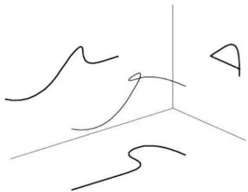
natural_image
Abstract 3D line drawing with curved and straight lines, no text or symbols presentKey-in: FLATTEN CURVE
Deform Curve

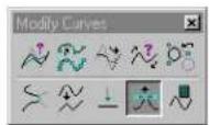
Used to deform a curve with restricted parameter domain.
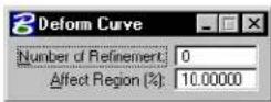
| Tool Setting | Effect |
| Number of Refine-ment | Defines the number of parameters or degrees of freedom to be added to the region being deformed. The more you add, the more freedom you have to deform the curve. |
| Affect Region (%) | Defines the percentage of the total curve that is affected by the deformation. |
To deform a curve
- Select the Deform Curve tool.
- Set the Number of Refinement required to define the number of parameters, or degrees of freedom, to be added during the deformation.
- Set the Affect Region (%) to define the percentage of the overall curve that may be deformed.
- Identify the curve at the point at which you want the deformation to occur.
- Enter a data point to define the deformation.
Key-in: DEFORM CURVE
Evaluate Curve

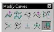
Used to graphically and numerically evaluate the attributes of a B-spline curve (tangents, curvatures, and inflection
points) at given locations on the curve. There are five ways to define locations on a curve.
Computed points and tangents, which are placed as elements in the design, can be used as reference points or reference lines for other purposes. Curvature displays indicate the slopes change as you traverse the B-spline. Flatter curves thus are indicated graphically with shorter lines. For example, straight lines have zero curvatures.
Below is an example of Evaluate Curve results specifying node points. Note that the number of node points is equal to the number of knots.
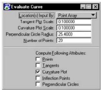
text_image
Evaluate Curve Location(s) Input By: Point Array Tangent Plot Scale: 0.100000 Curvature Plot Scale: 0.100000 Perpendicular Circle Radius: 25.4000 Number of Points: 20 Compute Following Attribues: Points Tangents Curvature Plot Inflection Points Perpendicular Circles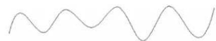
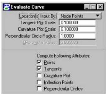
text_image
Evaluate Curve Location(s) Input By: Node Points Tangent Plot Scale: 0.100000 Curvature Plot Scale: 0.100000 Perpendicular Circle Radius: 1.0000 Parameter Value: 0.000000 Compute Following Attributes: ✓ Points ✓ Tangents □ Curvature Plot □ Inflection Points □ Perpendicular CirclesBy changing the number of points, the data may be viewed in a variety of pictorial formats.
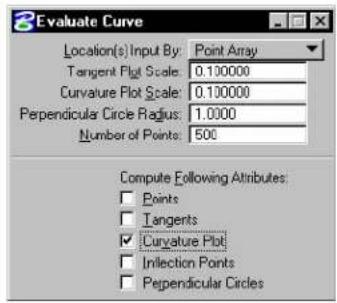
text_image
2 Evaluate Curve Location(s) Input By: Point Array Tangent Plot Scale: 0.100000 Curvature Plot Scale: 0.100000 Perpendicular Circle Radius: 1.0000 Number of Points: 500 Compute Following Attributes: Points Tangents Curvature Plot Infection Points Perpendicular Circles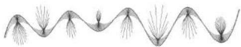
natural_image
Abstract wavy line pattern with branching structures (no text or symbols)This B-spline curve is identical to the one displayed in the table of tool setting descriptions. Note that increasing the number of points in the Curvature Plot and changing the Curvature Plot Scale, this image clearly shows the first derivative.
| Tool Setting | Effect |
| Location(s)Input By | Sets the manner in which the locations on the surface are defined.Enter Data Point—Interactively define a single location on the curve.Parameter—Using the Parameter Value setting, the value, which must be in the range 0–1, specifies the location from the domain to map to the displayed object. Within MicroStation, the domain is from 0.0 to 1.0.Node Points—These are the points on the curve calculated by evaluating it at the knots parameters. Node points represent the joints between the Bézier segments of a B-spline composed of Bézier segments separated by knots.Dist[ance] Along Curve—Using the Dist From Start setting, you can extract an attribute at a particular distance along the curve.(%) Dist[ance] Along Curve—Using the Dist From Start(%) setting, the value is a percentage of the total length of the curve. For example, to extract the tangent direction of a curve at its middle point, set Dist. From Start(%) to 50 (for 50% of the distance of the total curve length).Point Array—Using the Number of Points setting, the value is the number of evenly spaced locations on the curve. For example, to evaluate at 20 evenly spaced locations on the curve, set Number of Points to 20. |
| Tangent Plot Scale | Sets the scale factor applied to the magnitude display. If set to 1.0, the extracted tangent is the true derivative vector — that is, the tangent direction with the magnitude. |
| Curvature Plot Scale | Sets the scale factor applied to the line segments that represent curvature vectors in Curvature Plot output. If set to 1.0, the true curvature vector is displayed. The curvature value is the length of this vector. The radius of curvature is equal to one divided by the curvature. For a straight line, the radius of curvature is infinity since its curvature is zero. |
| Perpendicular Circle Radius | Sets the radius of the perpendicular circles in Perpendicular Circles output. |
| Parameter Value | Sets the parameter value applicable to the Parameter option for defining locations on the curve; see Location(s) Input By above. |
| Dist[ance] From Start | Sets the distance value applicable to the Dist Along Curve option for defining locations on the curve; see Location(s) Input By above. |
| Dist[ance] From Start(%) | Sets the distance value applicable to the (%) Dist Along Curve option for defining locations on the curve; see Location(s) Input By above. |
| Number of Points | Sets the numeric value applicable to the Point Array option for defining locations on the curve; see Location(s) Input By above. |
| [Compute] Points | 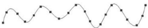 If on, the points on the curve at which evaluation is performed are displayed in the output. If on, the points on the curve at which evaluation is performed are displayed in the output. |
| [Compute] Tangents | 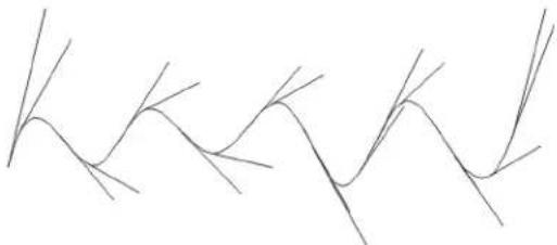 If on, the curve's tangents are computed. If on, the curve's tangents are computed. |
| [Compute] Curvature Plot | 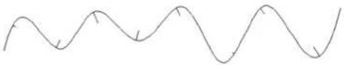 If on, the curve's curvature plot is computed. If on, the curve's curvature plot is computed. |
| [Compute] Inflection Points | 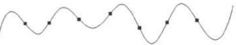 If on, the curve's inflection points are computed. Inflection points are where the curve changes concavity. If on, the curve's inflection points are computed. Inflection points are where the curve changes concavity. |
| [Compute] Perpendicular Circles | 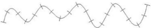 If on, the curve's perpendicular circles are computed. If on, the curve's perpendicular circles are computed. |
To evaluate a B-spline curve
- Select the Evaluate Curve tool.
- Identify the curve.
If Location(s) Input By is set to Enter Data Point, this data point also determines the location on the curve at which to evaluate.
- Accept the curve.
The curve is evaluated, and the desired attributes are computed and output.
Key-in: EVALUATE CURVE

This tool can also be used to evaluate lines, arcs, and ellipses.
Selecting Elements Based on Attributes
In addition to graphically selecting elements with the Element Selection tool (see "Selecting Elements" on page 4-1), you can easily select them based on their attributes using the Select By Attributes dialog box. The dialog box has controls for specifying attribute-based search criteria. In essence, the dialog box is an extension of the Element Selection tool.
For example, you can request MicroStation to select all text elements or all elements with line weight 3. You can even specify search criteria based on different kinds of attributes — for example, green, dotted arc elements on level 22 and level 23.
Any kind of attribute can be specified as search criteria:
• level
- type (such as line, arc, B-spline, text)
• color
- line style
- line weight
· c l a s s
- tag values (see Selecting Tagged Elements in the Guide to Generating Drawings)
- properties, including the area attribute (Solid or Hole), whether an element can be snapped to, whether it is locked, and whether it has been modified.
General Procedure — To use Attributes as Selection Criteria
- From the Edit menu, choose Select By Attributes.
The Select By Attributes dialog box opens. The second option
menu in the Mode section should be set to Selection.
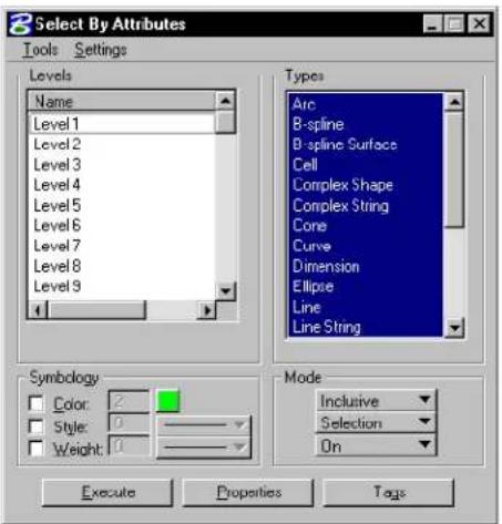
text_image
8 Select By Attributes Tools Settings Levels Name Level 1 Level 2 Level 3 Level 4 Level 5 Level 6 Level 7 Level 8 Level 9 4 Types Arc B-spline B-spline Surfaces Cell Complex Shape Complex String Cone Curve Dimension Ellipse Line Line String Symbology Color: 2 Style: 0 Weight: 10 Mode Inclusive Selection On Execute Properties Tags- Use the controls in the dialog box to specify selection criteria. (To specify criteria based on element properties, click the Properties button and use the controls in the Select by Properties dialog box. To specify criteria based on tag values, click the Tags button and use the controls in the Select By Tags dialog box.)
- In the Mode section, make sure On is chosen from the third option menu.
- Click Execute.
The elements meeting the specified selection criteria are highlighted.

The above procedure can be adapted for locating (highlighting) elements or filtering their display based on their attributes. The effect of the Execute button in the Select By Attributes dialog box is controlled with the second option menu in the Mode section, which is set to Selection by default. The other options are Location and Display.
Using Auxiliary Coordinate Systems
You can define new x- and y- axes in your design plane and save them as an auxiliary coordinate system. You can save several auxiliary coordinate systems and quickly choose any of them to use, as well as the DGN file or view coordinate systems.
If you have an auxiliary coordinate system stored in another DGN file, you can import it into your current file.
The drawing plane coordinate system used with AccuDraw (see page 3-26) serves much the same function as an auxiliary coordinate system but is even more useful.

Auxiliary coordinate systems can be particularly helpful in 3D design, where they facilitate placing elements on planes at different depths and orientations. See “3D auxiliary coordinate systems” on page 8-66.

Once an auxiliary coordinate system is active you can use it with precision input key-ins (such as AX= and AD=) to perform precision input with respect to the auxiliary coordinate systems. See “Precision input key-ins with an ACS” on page 8-73.

To define and save an auxiliary coordinate system in a 2D design by datapoints
- (Optional) — From the Settings menu, choose View
Attributes (or press Ctrl-B )
or
From any view window's control menu, choose View Attributes.
The View Attributes dialog box opens.
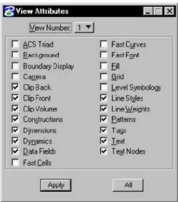
text_image
View Attributes View Number: 1 ACS Triad Background Boundary Display Camera Clip Back Clip Front Clip Volume Constructions Dimensions Dynamics Data Fields Fast Cells Fast Curves Fast Font Fill Grid Level Symbology Line Styles Line Weights Patterns Tags Text Text Nodes Apply All- (Optional) — In the View Attributes dialog box, turn on ACS Triad and click All.
When an auxiliary coordinate system is defined, two arrows indicating the positive x- and y- axes and their origin display. (This symbol is called a "triad" because it consists of three arrows in 3D designs.)
- From the Utilities menu, choose Auxiliary Coordinates.
The Auxiliary Coordinate Systems dialog box opens.
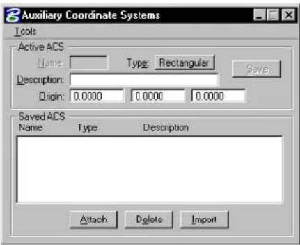
text_image
Auxiliary Coordinate Systems Tools Active ACS Name: Type: Rectangular Description: Origin: 0.0000 0.0000 0.0000 Save Saved ACS Name Type Description Attach Delete Import- From the dialog box's Tools menu's Define By Points
submenu, choose Rectangular.
The prompt in the status bar is "Enter first point @ x axis origin."
- Enter a data point to define the origin of the auxiliary coordinate system.
The coordinates of the point identified will be 0,0 in the auxiliary coordinate system. The prompt in the status bar is “Enter second point on x-axis.”
- Enter a data point to define a point on the positive x-axis.
The ACS triad displays.
-
In the Auxiliary Coordinate Systems dialog box's Name field, key in a name of up to seven characters to identify the auxiliary coordinate system.
-
(Optional) — In the Description field, key in a description of up to 28 characters to help identify the auxiliary coordinate system.
-
Click Save.
The new auxiliary coordinate system displays in the list box.
ACS tool box
The tools in the ACS tool box are used to define and manipulate an auxiliary coordinate system (ACS) — a coordinate system you define that differs from the design plane (world) and view coordinate systems. For general information about using an ACS, see “3D auxiliary coordinate systems” on page 8-66.
One ACS can be active at any time in a 2D or 3D design. While ACSs can be used in 2D, they are most useful in 3D design.
| To | Select in the ACS tool box |
| Define an ACS aligned with a planar element. |  Define ACS (Aligned with Element) (see page 7-139) Define ACS (Aligned with Element) (see page 7-139) |
| Define an ACS by entering data points. |  Define ACS (By Points) (see page 7-140) Define ACS (By Points) (see page 7-140) |
| Define an ACS aligned with a view. |  Define ACS (Aligned with View) (see page 7-141) Define ACS (Aligned with View) (see page 7-141) |
| Rotate the active ACS. |  Rotate Active ACS (see page 7-142) Rotate Active ACS (see page 7-142) |
| Move the origin of the Active ACS. |  Move ACS (see page 7-143) Move ACS (see page 7-143) |
| Identify an ACS for attachment a st h e A c t i v e A C S . |  Select ACS (see page 7-144) Select ACS (see page 7-144) |
Key-in: DIALOG TOOLBOX ACS [OFF | ON | TOGGLE]
Define ACS (Aligned with Element)

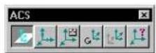
Used to define an ACS aligned with an existing element. Upon definition, the ACS becomes the Active ACS.
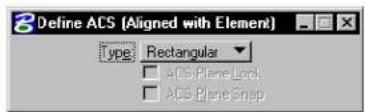
text_image
Define ACS (Aligned with Element) Type Rectangular □ ACS Plane Lock □ ACS Plane Snap| Tool Setting | Effect |
| Type Sets the ACS Type — Rectangular, Cylin-drical, or Spherical. | |
| ACS Plane Lock | If on, each data point is forced to lie on the Active ACS's xy-plane. |
| ACS Plane Snap | If on, each tentative point is forced to lie on the Active ACS's xy-plane. |
To define an ACS aligned with an element
- Select the Define ACS (Aligned with Element) tool.
- Enter a data point to identify the element with which to align the ACS and define the ACS origin.
- Accept the ACS.
The ACS is aligned with the selected element, its xy-plane parallel to the plane of the element.
Key-in: DEFINE ACS ELEMENT
Define ACS (By Points)

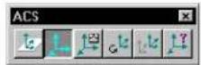
Used to define an ACS with data points. Upon definition, the ACS becomes the Active ACS.
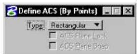
| Tool Setting | Effect |
| Type | Sets the ACS Type — Rectangular, Cylindrical, or Spherical. |
| ACS Plane Lock | If on, each data point is forced to lie on the Active ACS's xy-plane. |
| ACS Plane Snap | If on, each tentative point is forced to lie on the Active ACS's xy-plane. |
To define an ACS with data points
- Select the Define ACS (By Points) tool.
- Enter a data point to define the ACS origin.
- Enter a data point to define the direction of the ACS's positive
x-axis, which extends from the origin through this point.
- (3D only) Enter a data point to define the direction of the positive y-axis.
The direction of the positive z-axis follows by applying the "right hand rule."
Key-in: DEFINE ACS POINTS
Define ACS (Aligned with View)

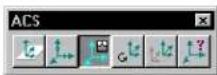
Used to define an ACS aligned with a view. Upon definition, the ACS becomes the Active ACS.
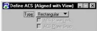
| Tool Setting | Effect |
| Type Sets the ACS Type — Rectangular, Cylin-drical, or Spherical. | |
| ACS Plane Lock | If on, each data point is forced to lie on the Active ACS's xy-plane. |
| ACS Plane Snap | If on, each tentative point is forced to lie on the Active ACS's xy-plane. |
To define an ACS that is aligned with a view
-
Select the Define ACS (Aligned with View) tool.
-
Enter a data point to select the view with which the ACS is to be aligned and define the ACS origin.
The ACS's axes align with the x-, y-, and z-axis (3D only) of the view.
Key-in: DEFINE ACS VIEW
Rotate Active ACS

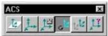
Used to rotate the Active ACS. The origin is not moved. After keying in rotation angles for the x-, y-, and/or z-axes, Absolute and Relative buttons let you choose whether to rotate the ACS relative to a Top view orientation (Absolute) or relative to its current orientation (Relative).
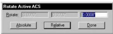
text_image
Rotate Active ACS Rotate: 0.0000 0.0000 0.0000 Absolute Relative DoneTo rotate the active ACS
- Select the Rotate Active ACS tool.
The Rotate Active ACS dialog box opens.
- In the Rotate fields, enter the rotation angles, in degrees,
from left to right, for the x-, y-, and z-axes. ^4
- Click either of the following buttons:
| To rotate Active ACS from Click | |
| Unrotated (top) orientation Absolute | |
| ACS's current orientation Relative |
- When you are finished, click Done to close the Rotate Active ACS dialog box.
Key-in: ROTATE ACS [ABSOLUTE | RELATIVE]
Move ACS

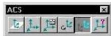
Used to movethe origin of the Active ACS.
To move the active ACS
- Select the Move ACS tool.
- Enter a data point to define the new origin.
The ACS Type and orientation do not change.
Key-in: MOVE ACS
Select ACS

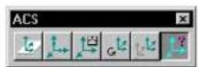
Used to identify an ACS for attachment as the Active ACS.
To select and attach an ACS
- Select the Select ACS tool.
A coordinate triad displays for the Active ACS, if there is one, and each saved ACS in each view that contains the ACS origin.
- Identify the ACS to attach.
Key-in: ATTACHACS
Digitizing
MicroStation requires that you use a digitizing tablet or table ^5 to perform digitizing. Digitizing is the process of electronically reproducing the features of an existing hard copy drawing or map into a MicroStation design. A large tablet or table is recommended.
Accurate digitizing requires careful planning and setup of the relationship between the hard copy, mounted on the tablet or table, and the design plane, represented on the screen.
For more details about setting up to use a digitizing tablet, see Graphical input with a digitizing tablet in the QuickStart Guide.
Setting up to digitize
- Create a DGN file and model.
- Set up appropriate working units.
- Set up appropriate views. It is recommended that you set up one of the views to encompass the entire drawing.
- (Optional) — Partition the digitizing tablet surface. See Digitizing tablet partitioning (below).
- Mount the hard copy to be digitized on the surface of the tablet. (Tape works well for mounting.) Locate the features you will be mapping to the DGN file over the digitizing partition, not over the screen partition.
- Place monument points that associate known points (of your choosing) on the hard copy with points in the design plane. See “Placing monument points” on page 7-146.
- From the File menu, choose Save Settings (or press Ctrl-F ) to save the working units, view configuration, and the relationships specified by monument points, digitizer partitioning and setup.
- Use any MicroStation drawing tool to trace the hard copy image. See "Tools for digitizing" on page 7-148.
Digitizing tablet partitioning
Partitioning divides the surface of the digitizing tablet into two areas or partitions. One area, the screen partition, continues to provide standard tablet-to-screen mapping. Within the screen partition, moving the tablet cursor results in a corresponding movement of the screen pointer, regardless of what is displayed on the screen. The other area is the digitizing partition. Within the digitizing partition, movement of the tablet cursor results in a corresponding movement of the screen pointer only within the part of the design plane to which you are mapping features of the hard copy.
After you partition the tablet surface, you will notice a change in the behavior of the screen pointer, depending on whether it is in the screen or digitizing partition. When in the screen partition, the pointer moves on the screen in direct proportion to the movement
of the tablet cursor. If you have two screens, the screen partition corresponds to the rectangular area encompassing both screens.
When the tablet cursor is in the digitizing partition, the tablet cursor position determines the position of the pointer in the design plane. MicroStation places the pointer in the first open view where the design plane position is visible. The open views are checked in sequence starting with the lowest numbered view. If the design plane position is not visible in any views, the pointer is not displayed. Nevertheless, even when you cannot see the pointer, you can continue to enter data points and place elements into the design.
The screen partition takes priority over the digitizing partition. If data points are entered in the screen partition, their position in the design plane reflects their position on the screen. Therefore, make sure not to stray into the screen partition while digitizing.

If the tablet surface is not partitioned, MicroStation defaults the screen partition to an 18 × 12 area (or smaller on a smaller tablet) in the lower left corner of the tablet surface.

To change the default digitizing and screen partitions on the tablet surface
- From the Workspace menu, choose Digitizing.
The Digitizing dialog box opens.
-
From the dialog box's Tablet menu, choose Partition.
-
Identify the lower left corner of the screen partition by placing the tablet cursor over it and pressing the Data button.
-
Identify the upper right corner of the screen partition by placing the tablet cursor over it and pressing the Data button.
Placing monument points
Monument points are used to define the mapping of coordinates on the digitizing tablet to coordinates in the design plane.
Thus, monument points are defined on both the digitizing
tablet surface and in the design plane.
At least two monument points must be defined; more are recommended for increased accuracy. When only two monument points are defined, MicroStation assumes the hard copy is perfectly aligned on the tablet surface. If more than two monument points are defined, MicroStation can compensate for misalignment.
A monument point can be any point at which the coordinates on the hard copy being digitized are known. It is best to define several widely spaced monument points.
It is easier to place monument points in the design plane before setting up for digitizing, and then snap tentative points to them during setup and digitizing. To make monument points visible, place them with a line weight of at least 3.
To place monument points that associate points on the hard copy with points in the design plane
-
(Optional) — Place point elements (zero length lines) for reference with line weights of at least 3 using the Place Active Point tool.
-
From the Workspace menu, choose Digitizing. The Digitizing dialog box opens.
-
From the dialog box's Tablet menu, choose Setup.
-
Choose a monument point on the hard copy, position the tablet cursor over it, and enter a data point. Ignore the location of the screen pointer, which only lets you know that the tablet cursor is over an active area of the tablet.
-
Move the tablet cursor into the screen partition and enter a data point in the design that corresponds to the monument point you chose in the previous step. Precision input, or snapping to a point
element, if one was placed for reference, is recommended.
-
Repeat steps 4 and 5 for additional monument points.
-
After placing all monument points, Reset.
-
Confirm accurate placement of the monument points by moving the cursor around the hard copy. If the monument points are correctly defined, the pointer displays in the design at points corresponding to the monument points.
Tools for digitizing
The Place Stream Line String tool (see page 2-27) and the Place Point or Stream Curve tool (see page 2-29) in the Linear Elements tool box are particularly useful. With these tools, it is not necessary to press the Data button to enter individual data points since MicroStation samples the movement of the tablet cursor and automatically records data points based on Stream.
Panning while digitizing
As hard copy is digitized, the design in the view normally remains static and the screen pointer moves as the tablet cursor is moved. You may find it more convenient to let the screen pointer remain stationary in the center of a view and have the view pan as the tablet cursor is moved.
To automatically pan this way while digitizing, key in SET AUTOPAN ON. The view in which the screen pointer is located when this key-in is entered becomes the anchor view, the view that is panned as digitizing progresses. The center of the view becomes the anchor point, the location in which the screen pointer is locked or anchored.
When automatic panning is on and the tablet cursor is in the screen partition of the digitizing tablet, the design will pan unless the pointer is in the center of the view. The effect is exactly as if you began panning at the center of the view, and is much less useful than the panning that occurs in the digitizing partition.
Therefore, you may want to turn automatic panning off (SET AUTOPAN OFF) when the tablet cursor is in the screen partition. To facilitate toggling of automatic panning, create and attach a cursor button menu with a button assigned to the key-in SET AUTOPAN TOGGLE
Advanced 2D Drafting Techniques
Panning while digitizing

text_image
83D Design and Modeling
MicroStation's 3D tools let you work on a single 3D model, rather than separate 2D models.
- When the 3D model is complete, drawings such as plans, elevations, sections, and details are generated from the single model. Any required modifications are made to the model just once, and then the drawings are regenerated.
- As an added benefit, you can use MicroStation's tools for rendering and visualizing 3D models to produce realistic color images of your design model. This is often more cost-effective than traditional mock-ups and artist's drawings, especially when there are frequent revisions or tight deadlines. Animated sequences provide a way to present a design that was not available before CAD.
In this chapter you will find procedures concerning 3D design and modeling, including:
• Basic 3D Concepts (see page 8-2)
• Viewing a 3D Model (see page 8-12)
• Using the Tools in the View Control tool box (see page 8-17)
• 3D Elements (see page 8-51)
• Drawing in 3D (see page 8-57)
• Using the Tools in the 3D Primitives tool box (see page 8-82)
• Using the Tools in the 3D Construct tool box (see page 8-100)
• Using the Tools in the 3D Modify tool box (see page 8-118)
• Using the Tools in the 3D Utility tool box (see page 8-144)
• Using the Tools in the Create Surfaces tool box (see page 8-162)
• Using the Tools in the Modify Surfaces tool box (see page 8-182)
• Using the Tools in the Fillet Surfaces tool box (see page 8-202)
• Using the Tools in the 3D Queries tool box (see page 8-210)
• Using Cells in 3D (see page 8-216)
DWG Restriction work mode and 3D
When you open a DWG file in MicroStation, various MicroStation tools are restricted to ensure compatibility with the DWG format. When you are required to create DGN files that are DWG compatible, you can turn on DWG Restriction work mode. In both cases, MicroStation restricts its tools to create only elements that are compatible with the DWG format. With 3D, this includes the following:
- Parasolids are disabled and 3D elements are created as ACIS bodies only.
• B-spline curves cannot be used in creating a complex chain or shape.
• Self-referencing of DGN files is disabled, as is reference clipping. - Raster references are disabled.
Basic3D Concepts
This section introduces the basic concepts related to working with 3D models.

Before working in 3D, you should understand the following:
- Placing Elements in 2D (see page 2-1)
• Drawing Technique (see page 3-1)
• Element Manipulation and Modification Tools (see page 4-1) - Advanced 2D Drafting Techniques (see page 7-1)
8-2 MicroStation User Guide
Design cube
3D DGN files consist of a design cube in which you work. The design cube represents a 3D DGN file's total volume, in which points are defined with x-, y-, and z-values, or coordinates. Points can be placed anywhere within the design cube, and are not restricted to a single plane as is the case when you work in a 2D DGN file.
The 2D design plane (top) and 3D design cube (bottom).
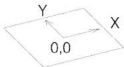
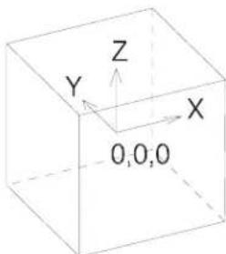
text_image
Y Z X O,O,ODesign cube coordinates are expressed in the form (x,y,z). The global origin in the 3D seed files provided with MicroStation is located at the exact center of the design cube and assigned the coordinates (0,0,0). Any point in front of (or above) the global origin has a positive z-value and any point behind (or below) it has a negative z-value.
View volume
The view volume (sometimes called the display volume) is the volume of the design cube that is displayed in a 3D view. In most cases, only a part of the design cube (see page 8-3) is displayed in a view.
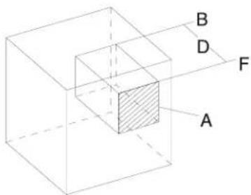
text_image
B D F AView volume. "A" denotes the window area (hatched). "D" denotes the Display Depth, bounded by the front "F" and back "B" clipping planes. The large cube shows the design cube, part of which is displayed in each view.
Any elements, or parts of elements, not contained in the view volume are not displayed in the view. Unless a clip volume has been applied to a view, the view volume is bounded by the window area, and its Display Depth.
You can set the clipping volume of a 3D view such that only the region of interest is displayed and you can snap to only those elements that are located within the defined clip volume of the view. Additionally, if you use the Fit View tool, only those elements within the clip volume are considered. This simplifies working on discrete portions of large and/or complicated 3D models (see "Apply Clip Volume To View view control" on page 8-49).
At any time, in a view, you can toggle on/off the view display restrictions of the front and/or back clipping planes. Similarly, you can toggle the clip volume, if one has been applied. Three settings in the View Attributes dialog box let you do this:
- Clip Back — if on, a back clipping plane is active in a view.
- Clip Front — if on, a front clipping plane is active in a view.
- Clip Volume — if on, and a clip volume has been applied to the view, the view volume is restricted to the defined clip volume.
Display Depth
The distance from the front to the back of a 3D view is its Display Depth. This depth is bounded by clipping planes, unless they have been disabled in the View Attributes dialog box. When clipping planes are on:
- The front clipping plane is nearest the viewer.
• The back clipping plane is farthest from the viewer.
Elements in front of the front clipping plane, or behind the back clipping plane, are not displayed in the view. This applies even if they are within its viewing area, regardless of how far the view is zoomed out. In other words, the front and back clipping planes define a “slice” of the total volume of the design cube. Only elements located within this slice can be displayed in a view. You can change the position of these front and back clipping planes with the Set Display Depth view control (see page 8-22), or when you fit a view, with Expand Clipping Planes turned on (this setting causes the display depth to be adjusted, along with the window area, so that all elements are displayed).
When a clip volume has been applied to a view, and Clip Volume is enabled (in the View Attributes dialog box), then this is the maximum volume of the design cube that will be displayed in that view. Clipping planes can be set that reduce this volume, but they have no effect if they are set outside the clip volume.
Active Depth
The Active Depth in a view defines the position of a plane, parallel to the screen, on which data points are entered by default. The Active Depth is perpendicular to, and is measured along, the view's z-axis. For this reason, it is sometimes referred to as the “active z-depth.”
Active Depth, denoted by "AZ." "x," "y," and "z" denote the View axes. "F" and "B" denote the front and back clipping planes, respectively.
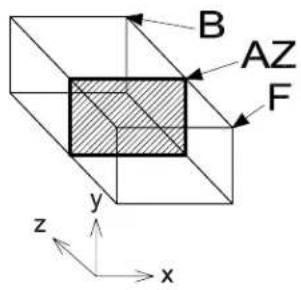
text_image
B AZ F y z xFor example, suppose you are modeling the interior of a multi-story building. You can complete the details on one floor at a time in the top view by setting the Display Depth and Active Depth to each floor successively. An even better method is to create a 3D clipping element (such as an extruded block) that encloses a single floor of the building and then use the Apply Clip Volume To View view control to "hide" all other geometry. With this set up, to view any particular floor, you would move the clipping element to the level of the floor that you wanted to work on, and the display volume would change accordingly.
You set the Active Depth with the Set Active Depth view control (see page 8-25). Also, you can change the Active Depth by completing a view manipulation — for example, Rotate View, Fit View, Change View Perspective — for which you snapped to an element for the first data point.

A view's Active Depth always lies within its Display Depth (see page 8-5).

Although Active Depth is a very powerful concept, MicroStation also lets you position points away from the Active Depth. For example, using AccuDraw in 3D, you can work at a particular depth without having to first set the Active Depth. For more information, see "Drawing in 3D" on page 8-57.
Standard views
If you rotate a view to a standard orientation, the view orientation displays, along with the view number, in the view's title bar.
2D
In 2D, the design plane is parallel to the screen and, in effect, you view the model from above. The default (unrotated view) in 2D is like a Top view with its orientation such that:
• The x-axis is positive from left to right (horizontally).
- The y-axis is vertical, and positive from bottom to top (vertically).
In a 2D model, you rotate a view about an imaginary z-axis, which is perpendicular to the screen. No matter how you rotate a view in 2D, effectively, you still view it from above.
3D Orthogonal views
In 3D, since you can rotate views about three axes, rather than just one, there are six orthogonal orientations, each of which corresponds to a standard orthogonal view: Top, Bottom, Left, Right, Front, or Back.
The faces of this cube correspond to the 3D orthogonal views. The cube is displayed here in an Isometric view.
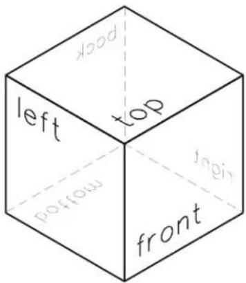
text_image
top left top frontTop view
A Top view displays the model from the top:
• the xy plane is parallel to your screen (as in a 2D model).
- x is positive from left to right (horizontally).
- y is positive from bottom to top (vertically).
- z is positive toward you, perpendicular to the screen.
Front view
A Front view displays the model from the front:
- the xz plane is parallel to your screen.
- x is positive from left to right (horizontally).
- z is positive from bottom to top (vertically).
• y is positive away from you, perpendicular to the screen.
Right view
A Right view, displays the model from the right:
• the yz plane is parallel to your screen.
• y is positive from left to right (horizontally).
- z is positive from bottom to top (vertically).
• x is positive toward you, perpendicular to the screen.
Similarly, the remaining orthogonal views display the model from the Left, Bottom, and Back.
Isometric views
There are two other standard views — Isometric and Right Isometric. These views are rotated so the three faces of a cube orthogonal to the design cube axes are equally inclined from the screen surface.
| Standard view | Faces in front |
| Isometric Top, Left, and Front | |
| Right Isometric Top, Right, and Front | |
Isometric view (left) and Right Isometric view (right).
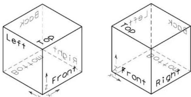
text_image
BOOK Left Top B0+OU Top FRONT x y z Front Top B0+OU x y z Front Right x y zView coordinates
Working in 3D, in every view we always have at least two coordinate systems to work with — the DGN file coordinate system and the view coordinate system. Only in a Top view, do the two coordinate systems align exactly. When we rotate a view, in reality we are repositioning our view “camera” to let us see the model from a different direction. Thus, when we rotate a view, the DGN file’s axes rotate with it. Each view’s axes, on the other hand, are relative to the view (or, if you like, the screen) and the following always applies for view axes:
• The x-axis is horizontal and positive from left to right.
• The y-axis is vertical and positive from bottom to top.
• The z-axis is perpendicular to the view (screen), and positive toward you.
Thus, you can place elements relative to the DGN file coordinates, or relative to the view coordinates. When you use AccuDraw, this is easier to understand as its compass gives you a visual indication of the drawing plane in which you are working.
Perspective projection
Elements in 3D models must be displayed on the screen, which is planar.
- In a view with parallel projection, each element is projected to the screen along a line parallel to the view's z-axis. Although parallel projected views make drawing easier, they lack realism because elements have the same relative size regardless of their depth in the view. With parallel projection it can be difficult to decipher the orientation of the model.
- In a view with perspective projection, elements at greater depths appear relatively smaller, enhancing realism. A view with perspective projection is also referred to as a camera view.
Example of parallel projection (left) compared to a perspective view (right).
natural_image
Pure 3D geometric line drawing of a stepped structure without any text, numbers, or symbols
natural_image
Line drawing of a 3D stepped structure with no text or symbolsUsing the grid in 3D
In a 3D DGN file, you can define the orientation of the grid to suit the task at hand. Once you define a grid, Grid Lock works as expected and input points are constrained to the grid points. The Grid Orientation is controlled from the Grid section of the DGN File Settings dialog (select Settings > Design File). Options are:
• View — Grid always aligns to the view and passes through the global origin.
- ACS — Grid aligns to the active ACS.
- Top — Grid aligns to a "Top" view. It extends along the X and Y axes from the global origin.
- Right — Grid aligns to a "Right" view. It extends along the Y and Z axes from the global origin.
- Front — Grid aligns to a "Front" view. It extends along the X and Z axes from the global origin.
Added to these options, is a key-in that lets you rotate the grid about (its) Z-Axis. This key-in, ACTIVE GRIDANGLE
When you define a grid to align to an ACS or a view orientation, it will rotate with that view, or display with perspective in camera views.
Perspective view displaying the grid with Orientation set to Top.
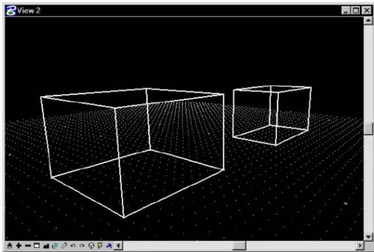
natural_image
3D wireframe cube and cube with dotted grid background, displayed in a software interface window (no text or symbols on the cube itself)Viewing a 3D model
A 3D view can display part of the design cube (see page 8-3) from any point, looking in any direction.
- As in 2D, elements to the left, right, above, or below, can be excluded from a view by zooming in or windowing so that the elements are outside the view's area.
- 3D views also have depth. You can exclude the display of elements located in front of, or behind, a required object by changing the view's Display Depth (see page 8-5), or by applying a clip volume.
3D viewing procedures that are similar to 2D
Many 3D viewing procedures are similar to their 2D counterparts. For example, you can change a view's area using the same tools as for 2D. Tools such as the Window Area, Zoom In, and Zoom Out view controls are used.
Fitting views in 3D
The Fit View view control has some 3D-specific aspects and settings.
| Expand Clipping Planes | If on, the view's Display Depth is adjusted, along with the view origin and magnification, so that all elements on levels that are on for the view are displayed. |
| Center Active Depth | If on, centers the Active D e p t h i n t h e f i t t e d v i e w . (I t is recommended that you turn on Center Active Depth when fitting a view you intend to dynamically rotate, or a view whose perspective you intend to change.) |
| Center Camera | If on, centers the Camera in the fitted view. |

When a clip volume has been applied to a view, the Fit View tool has no effect on the volume displayed in the view, it merely fits the view to the elements contained within the applied clip volume.
Rotating views in 3D
The Rotate View view control is used in 3D to rotate a view to one of the standard views (see page 8-7) as well as to custom orientations. For custom rotations, the Rotate View view control gives you two options for visual feedback during view rotation. With Method set to Dynamic and:
- Dynamic Display turned off — a dynamically displayed cube helps you define the rotation.
- Dynamic Display turned on — you see the elements rotate dynamically as you rotate the view.
When rotating views in 3D, an important point to consider is the axis about which you want the view to rotate. During a view rotation, the first data point that you place defines the rotation axis. In 3D, this also
defines the depth in the view of the rotation axis. Entering the data point in a vacant part of the view means that the rotation axis is on the Active Depth. If this is far behind the elements in the view, then you can quickly rotate the model out of sight. A simple way around this is to first snap to an element in the view and then accept with a data point. This will set the rotation axis at the depth of the snapped element and force rotation about the snap point on the element.
To dynamically rotate a view in 3D using a cube
-
Select the Rotate View view control.
-
Set Method to Dynamic and check that Dynamic Display is turned off.
-
Enter a data point in the view to rotate (this will be the point about which rotation will occur).
A cube representing the view volume dynamically displays. To further assist you, one of the cube's faces is displayed in a heavier line weight indicating the front face. As you move the screen pointer, the cube rotates to show you the amount of rotation. The location of the original view is shown as a cube in a lighter weight line.
- Enter a second data point to complete the rotation.
To dynamically rotate a view using dynamic display
-
Select the Rotate View view control.
-
Set Method to Dynamic.
-
Turn on Dynamic Display.
-
Enter a data point in the view to rotate (this will be the point about which rotation will occur).
As you move the screen pointer from this first data point, the view is rotated. The elements also rotate dynamically with the view.
- Enter a second data point to define the view orientation.
▶ Torotateaviewin3Dbythreepoints
- Select the Rotate View view control.
- Set Method to 3 Points.
- Enter a data point to select the view to rotate and to define the origin of the view x-axis.
The origin, as well as a dynamic line indicating the positive direction of the view x-axis, displays in all views where it is possible.
- Enter a data point to define the positive direction of the view x-axis.
A rectangle that indicates the new view boundary displays only in the view that is being rotated.
- Enter a data point in any view to define the positive direction of the view y-axis and rotate the view.
To rotate a view(s) in 3D to a standard orientation
- Select the Rotate View view control.
- Set Method to the desired standard orientation — Top, Front Right, Isometric, Bottom, Back, Left, or Right Isometric.
- Select the view(s).
Panning views in 3D
Panning in 3D models, using the Pan View view control, gives you two options for determining the amount to pan the view. If Dynamic Display is off, a dynamic cube is displayed between the origin and the pointer (rather than an arrow as in 2D), indicating the distance and direction that the view will be moved. If Dynamic Display is turned on, then the elements in the view are panned dynamically.
3D-specific viewing procedures
In addition to the familiar 2D viewing procedures, in 3D you can:
- Limit the depth of the view volume (see page 8-3) using the Set Display Depth view control (see page 8-22).
- Change the perspective angle of a view using the Change View Perspective view control (see page 8-21) or the Camera Settings view control (see page 8-29).
Display of the view volume in the other views is apparent only when they display the same volume of the design cube as the selected view. Where necessary, you can use the ALIGN key-in to ensure that views are displaying similar volumes of the design cube.
To align two views to display the same volume
-
Key in ALIGN.
-
Select the source view.
-
Select the view(s) to align with the source view.
The second (and other) selected target view updates to display (at least) the same volume of the model as displayed in the source view. The orientation of the target views is not changed, only the view volume.
Using saved views in 3D
Creating saved views in 3D is identical to 2D. Like 2D saved views, those in 3D modeling “remember” various parameters concerning the view, which levels are on and off in both the active model and any references, and the region of the model that is displayed. Additionally, the Display Depth is saved with a 3D saved view, as is the Clip Volume if one is applied.
The following categories of settings can be saved with a saved view:
- window aspect ratio, size, or size and position
- camera position
• view attributes - clip volume
- level display
- reference settings
When creating saved views in 3D, thought should be given to the Display Depth and Clip Volume (if applied).
View Control tool box
The View Control tool box contains tools for manipulating views in the active DGN file. Tools that are 3D specific are disabled when working in a 2D model.
| To | In the view control bar for the view in qstion, select |
| Update (redraw) a view(s). |  Update View Update View |
| Increase the magnification of a view. |  Zoom In Zoom In |
| Decrease the magnification of a view. |  Zoom Out Zoom Out |
| Window an area in a view. |  Window Area Window Area |
| Display all displayable elements in the active design and attached references in a view. |  Fit View Fit View |
| To | In the view control bar for the view in question, select |
| Rotate the view. |  Rotate View Rotate View |
| View a different part of the design without changing the view magnification. |  Pan View Pan View |
| Undo the last viewing operation. |  View Previous View Previous |
| Redo the last undone viewing operation. |  View Next View Next |
| Copy contents of one view to another. |  Copy View Copy View |
| Change the magnification of the view volume. |  Zoom In/Out (see page 8-20) Zoom In/Out (see page 8-20) |
| (3D only) Change the perspective angle of a 3D view. |  Change View Perspective (see page 8-21) Change View Perspective (see page 8-21) |
| (3D only) Set a view's Display Depth. |  Set Display Path (see page 8-22) Set Display Path (see page 8-22) |
| (3D only) Set a view's Active Depth. |  Set Active Depth (see page 8-25) Set Active Depth (see page 8-25) |
| To | In the view control bar for the view in question, select |
| (3D only) Show the Display Depth setting for a view(s). |  Show Display Depth (see page 8-27) Show Display Depth (see page 8-27) |
| (3 D only) Show the Active setting for a view(s). | I. h  Show Active pth (see page 8-28) Show Active pth (see page 8-28) |
| (3 D only) Adjust the view of | a  C a Settings (see page { C a Settings (see page {  |
| Render a view(s), the fence contents, or an element(s). |  Render1 Render1 |
| (3D only) Apply a clip volume to a view. |  Apply Clip Volumeto View (see page 8-49) Apply Clip Volumeto View (see page 8-49) |
1 Also in the Rendering Tools tool box.
Key-in: DIALOG TOOLBOX VIEWCONTROL(OFF | ON)
Where you have particular view controls that you use regularly, you can customize the view control bar used with 3D DGN files to include additional 3D-specific view controls, such as Apply Clip Volume To View (see "View Control Bars" in the Administrator Guide).
Zoom

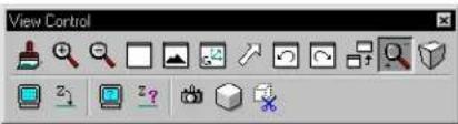
text_image
View Control(3D only) Used to change the magnification of the view volume. In a view with perspective projection, the eye point position is changed relative to a point in the view volume — usually a point on an element. The way in which this view control behaves, depends on whether or not Dynamic Display is active.
Currently, this tool takes its Dynamic Display setting from the following view controls — Rotate View, Pan View, and Change View Perspective.
To zoom in or out of a 3D view
-
Select the Zoom view control.
-
Enter a data point to define an origin to zoom about. This point becomes the center point in the view volume and sets the Active Depth.
A cube dynamically displays, representing the view volume to be displayed.
- Enter a data point to define the extent of the volume to be displayed.
To zoom in, this cube should be small; to zoom out, it should be big.
With Dynamic Display off, the original cube remains displayed, and another cube displays. This second cube indicates the defined volume. Making this second cube larger or smaller than the first, zooms the view in or out respectively.
With Dynamic Display on, the view updates to center the display of the elements in the defined volume. Moving the pointer away or toward the center of the view zooms the view in or out respectively.
- Enter a data point to complete the zoom action.
Key-in: ZOOM 3D

Rather than changing the perspective angle as does a camera's zoom lens, this view control lets you move closer to or further away from an element. (A zoom lens is useful with a real camera because it is often inconvenient to actually move closer to or further from the subject. In a computer model this is no problem.)
Change View Perspective


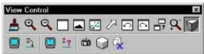
text_image
View Control(3D only) Used to change the perspective angle of a view. Setting perspective, in a view, is the same as turning on the view camera, with Three Point projection.
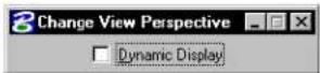
To change the perspective angle of a view
-
Select the Change View Perspective view control.
-
In the desired view window, enter a data point to define the "from" point.
As you drag the pointer toward or away from the center of the view, the view cube dynamically displays.
- In the same view window, enter a data point to define a "to" point.
If the "to" point is closer to the center of the view than the
“from” point, the perspective angle will be reduced (less perspective), or vice versa. Elements on the active depth plane remain the same size while those in front or behind the active depth plane appear to change size.
Change View Perspective
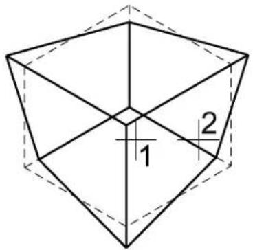
text_image
1 2Key-in: CHANGE VIEW PERSPECTIVE

To remove all perspective, enter the first point near the edge of the view and the second near the center. This is equivalent to turning off the view camera, or setting it to Parallel projection.
Set Display Depth

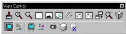
text_image
View Control(3D only) Used to graphically set a view's Display Depth (see page 8-5) — the front and back clipping planes (boundaries) of the volume displayed in a view. The position of each clipping plane is measured along the view's z-axis. Only elements or parts of elements between
8-22 MicroStation User Guide
the front and back clipping planes are displayed.
To set the Display Depth graphically
- Be sure at least two views are open.
It is helpful to have a view open that is orthogonal to the view in which the Display Depth is being set, as well as an isometric view.
-
Select the Set Display Depth view control.
-
Select the view in which to set the Display Depth.
If an isometric view is open, dynamics (as shown in the illustration) indicate the selected view's Display Depth. As you move the pointer in a different view, a shape indicates where the first depth boundary will be placed.
- Define the front clipping plane.
| To set front clipping plane to | Enter a data point in |
| Active Depth The view | for which Display Depth is being set. |
| Depth other than Active Depth | A view other than the one for which Display Depth is being set, at the desired depth. ^2 |
2 The view's Active Depth, which is set with the Set Active Depth view control, must be within its Display Depth.
- In a view other than the one for which Display Depth is being set, enter a data point to define the back clipping plane.
If you specify the same plane for the front and back clipping
planes, a message displays and the Display Depth does not change.
text_image
Top 1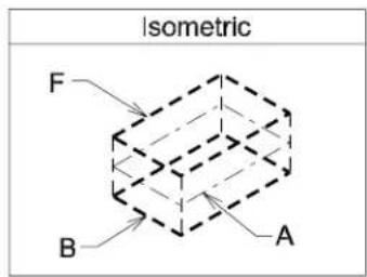
text_image
Isometric F B A
text_image
Front 2 3Setting the Display Depth in the Top View (selected with data point 1) by entering data points in the front view (2 and 3) to define the front and back clipping planes, respectively.
Dynamics in Isometric view indicate the following for view in which Display depth is set: "F": Front clipping plane (2). "B": Back clipping plane (3). "A": Active Depth.
To key in a view's Display Depth
- Key in SET DDEPTH ABSOLUTE front, back.
or
Key in DP= front,back.
Front and back are the distances, in working units, along the view z-axis from the Global Origin to the desired front and back clipping planes.
- Select the view(s).
If the Active Depth is not within the range specified by the Display Depth, the Active Depth is automatically changed to the front clipping plane.
To key in the distance to move the Display Depth
- Key in SET DDEPTH RELATIVE front, back.
or
DD= front,back.
Front and back are the distances, in working units, to move the front and back clipping planes, respectively.
- Select the view(s).
If the Active Depth is not within the range specified by the Display Depth, the Active Depth is automatically changed to the front clipping plane.
Key-in: DEPTH DISPLAY

If dynamics do not display in the Isometric or another view (do not fit), use the Zoom Out or Fit View view controls in the view control bar until the view can display the dynamics.
Set Active Depth

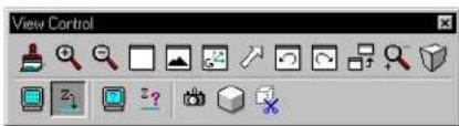
text_image
View Control(3D only) Used to graphically set a view's Active Depth (see page 8-5) — the plane, parallel to the screen in a view, on which data points are entered by default. The Active Depth's value is measured along the view's z-axis.
The Active Depth must be within the view's Display Depth, which is set with the Set Display Depth view control (see page 8-22).
To set the Active Depth graphically
- Make sure at least two views are open.
It is helpful to have a view open that is orthogonal to the view in which the Active Depth is being set, as well as an isometric view.
-
Select the Set Active Depth view control.
-
Select the view in which to set the Active Depth.
If an isometric view is open, dynamics (as shown in the illustration) indicate the selected view's Display Depth. As you move the pointer in a different view, a shape indicates the depth of the pointer.
- Enter a data point in a different view at the desired Active Depth for the view selected in step 3.
It is often useful to snap to an existing element in the design when you want to place other elements at the same depth.

If useful dynamics do not display in the Isometric view, use the Zoom Out or Fit View view controls in the view control bar until the isometric view can display the volume contained by the view for which the Active Depth is being set.
Setting the Active Depth in the Topewi (selected with data point 1) by entering a data point (2) at the desired depth in the Frontview. Dynamics in Isometric view show for the Top view: "F:" Front clipping plane. "B" Back clipping plane. "A:" Active Depth.
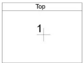
text_image
Top 1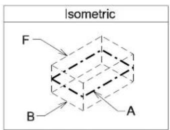
text_image
Isometric F B A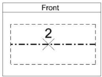
text_image
Front 2To key in the Active Depth
- Key in ACTIVE ZDEPTH ABSOLUTE
.
or
Key in AZ=
Depth is the distance in working units along the view z-axis from the Global Origin to the desired Active Depth.
- Select the view(s).
If depth is not within the view's Display Depth, the Active Depth is automatically changed to the front clipping plane. The change is indicated in the status bar.
To key in the distance to move the Active Depth
- Key in ACTIVE ZDEPTH RELATIVE
.
or
Key in DZ= DISTANCE.
Distance is the distance, in working units, to move the Active Depth along the view z-axis.
- Select the view(s).
If distance is not within the view's Display Depth, the Active Depth is automatically changed to the front clipping plane. The change is indicated in the status bar.
Key-in: DEPTH ACTIVE
Show Display Depth

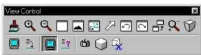
text_image
View Control(3D only) Used to show a view's Display Depth (see page 8-5) setting.
To show the Display Depth setting for a view
- Select the Show Display Depth view control.
- Select the view.
The view's Display Depth setting is shown in the status bar. - Go back to step 2 to show the Display Depth for another view.
Key-in: SHOW DEPTH DISPLAY

A view's Display Depth is set with the Set Display Depth view control (see page 8-22).
Show Active Depth

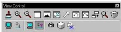
text_image
View Control(3D only) Used to show a view's Active Depth (see page 8-5) setting.
To show the Active Depth setting for a view
- Select the Show Active Depth view control.
- Select the view.
The view's Active Depth setting is shown in the status bar. - Go back to step 2 to show the Active Depth setting for another view.
Key-in: SHOW DEPTH ACTIVE

A view's Active Depth is set with the Set Active Depth
view control (see page 8-25).
Camera Settings

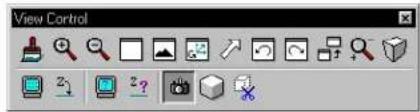
text_image
View ControlUsed to directly adjust the virtual camera (as an alternative to using the Change View Perspective view control (see page 8-21)).
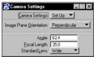
text_image
Camera Settings Camera Settings Set Up Image Plane Orientation Perpendicular Angle 62.4 Focal Length 35.0 Standard Lens Wide| Tool Setting | Effect |
| Camera Settings | Determines the operation to be performed:Turn On—Used to turn on the camera in a view(s).Turn Off—Used to turn off the camera in a view(s).Set Up—Used to turn on the camera in a view and set the camera target and position. The position is the design cube location from which the model is viewed with the camera. The target is the focal point (center) of a camera view. Objects beyond the camera target appear smaller; objects in front of the camera target appear larger and may be outside of the viewing pyramid.Move—Used to move the camera position relative to the target. This operation is comparable to focusing a camera at an object and moving around it to obtain different views of it.Target—Used to move the camera target. This operation is comparable to standing in one position and panning the camera to view different objects. |
| Image Plane Orientation | Sets the orientation of the plane on which the camera image is represented.Perpendicular—Perpendicular to the camera direction.Parallel to X Axis—Parallel to the view x-axis, analogous to a Bellow camera.Parallel to Y Axis—Parallel to the view y-axis, analogous to a Bellow camera.Parallel to Z Axis—Parallel to the view z-axis. All vertical lines (along this axis) appear parallel. |
| Angle | Sets the camera “lens” angle, in degrees. Increasing this setting widens the field of vision (and decreases the Focal Length). |
| Focal Length | Sets the camera “lens” focal length, in millimeters (MM). Decreasing this setting widens the field of vision (and increases the Angle). |
| Standard Lens | Sets the camera “lens” Angle and Focal Length to values associated with a standard lens type commonly used by photographers.Fisheye—93.3 ^ ; focal length 20mmExtra-wide—74.3 ^ ; focal length 28mmWide—62.4 ^ ; focal length 35mmNormal—46.0 ^ ; focal length 50mmPortrait—28.0 ^ ; focal length 85mmTel ep hoto—12.1; focal length 200mmTelescopic—2.4 ^ ; focal length 1000mm |
To turn on the camera in a view
- Select the Camera Settings view control.
- In the Tool Settings window, set Camera Settings to Turn On.
- Select the view(s).
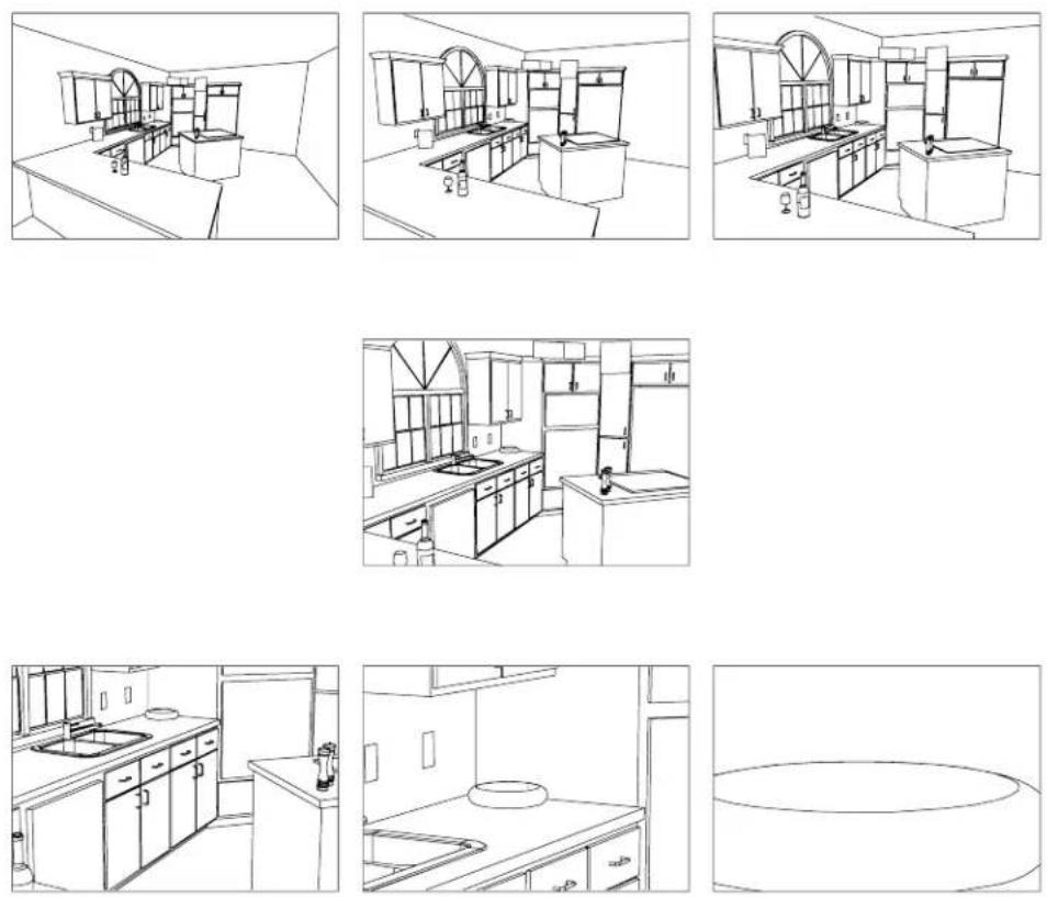
Top: Fisheye (left); Extra-wide (center); Wide (right).
Middle: Normal. Bottom: Portrait (left); Telephoto
(center); Telescopic (right).
To turn off the camera in a view
- Select the Camera Settings view control.
- In the Tool Settings window, set Camera Settings to Turn Off.
- Select the view(s).
To turn on the camera and set the target and position
- Select the Camera Settings view control.
- In the Tool Settings window, set Camera Settings to Set Up.
- Select the view.
- Enter a data point to define the camera target — the focal point (center) of the view.
A dynamic pyramid displays to show the viewing volume with the camera at the pointer location. - Enter a data point to define the camera position.
The camera is turned on.
To move the camera
- Select the Camera Settings view control.
- In the Tool Settings window, set Camera Settings to Move.
- Select the view.
A dynamic pyramid shows the viewing volume with the camera at the pointer location. - Enter a data point to define the new camera position.
If the camera was off, it is turned on.
To move the target
- Select the Camera Settings view control.
- In the Tool Settings window, set Camera Settings to Target.
- Select the view.
A dynamic pyramid shows the viewing volume with the camera target at the pointer location. - Enter a data point to define the new camera target.
If the camera was off, it is turned on.
Key-in: SET CAMERA

Setting Image Plane Orientation to Parallel to Z Axis is useful for architectural renderings as it ensures buildings appear vertical from any camera position.

The virtual camera has advantages over conventional cameras. All elements in the field of view are in focus, no matter how close to or far from the camera. You need not worry about depth of field, aberrations, astigmatism, or curvature of field — in a sense, the virtual camera takes a “perfect” picture.
Set View Display Mode

Used to set the Display Mode and to apply accelerated rendering to any view in MicroStation.
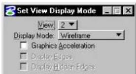
text_image
Set View Display Mode View: 2 Display Mode: Wireframe Graphics Acceleration Display Edges Display Hidden Edges| Tool Setting | Effect |
| View | Sets the view to which to apply accelerated rendering. |
| Display Mode | Sets the mode of rendering: Wireframe, Wiremesh, Hidden Line, Filled Hidden Line, Constant, Smooth (Gouraud), or Phong. |
| Graphics Acceleration | If on, the view is displayed using QuickVision. |
| Display Edges | (Graphics Acceleration on only) If on, all visible edges are displayed. |
| Display Hidden Edges | (Graphics Acceleration on only) If on, all hidden edges are displayed. |
To change a view's Display Mode
- Select the Set View Display Mode view control.
- In the settings window, choose the number of the view whose display mode you want to change.
- From the Display option menu, choose the desired Display Mode.
Alternative method — To change a view's Display Mode
- From the Settings menu, choose Rendering > View Attributes.
The Rendering View Attributes dialog box opens. - From the View Number option menu, choose the number of the view whose display mode you want to change.
- From the Display option menu, choose the desired Display Mode.
- Click the Apply button.
These other rendering view attributes are also set in the Rendering View Attributes dialog box:
- If Delayed Display is on, the view is not updated until rendering is complete. This reduces rendering time and, for low-color displays, improves image quality.
- If Graphic Acceleration is on, the view is eligible to be drawn using QuickVision.
Key-in: CHANGE VIEW DISPLAYMODE
Navigate Camera

(3D only) Used to interactively move or "fly" through a design using the keyboard and/or the mouse.
When you open the Navigate Camera view control for the first time, it is in Basic Mode. In Basic Mode, navigation options for the keyboard and the mouse are predefined, so you can move through a design immediately, without adjusting any settings. In Advanced Mode, you can change the default navigation options.
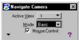
The following list contains all the keyboard shortcuts used to control camera movement, speed, and orientation.
| Keyboard Key Effect | |
| Left arrow, A or J | Same as moving the mouse to the left. |
| Right arrow, D or L | Same as moving the mouse to the right. |
| Up arrow, W or I | Same as moving the mouse forward. |
| Down arrow, S or K | Same as moving the mouse backward. |
| Keyboard Key Effect | |
| Home, Q or U | Resets the camera's roll, elevation, and orientation (see the Roll, Elevate, and Orient fields under Camera Orientation in the Define Camera tool settings window).Fore x a m p l e , press i n g t h e H o m e k y o n y o u r keyboard: once - resets the camera's tilt angle to zero degrees (roll). twice - resets the roll, then resets the camera's elevation angle to zero degrees (camera is horizontal to the ground). three times - resets the roll, then resets the elevation, then resets the camera's orientation angle to zero degrees (camera is in the direction of the positive X-axis). |
| + | Increases the Distance field by 10 percent. Fore x a m p l e , if y o u r D i s t a n c e i s s e t t o 10 (feet), pressing the + key on your keyboard increases the Distance to 11 feet. Changes are applied to both the Arrow Keys and the Mouse column. |
| I | Increases the Degrees field by 10 percent. Fore x a m p l e , if y o u r D e g r e e s i s s e t t o 30, pressing the I key on your keyboard i n cre a s e s t h e D e g r e e s t o 3 3 d e g r e e s . Changes are applied to both the Arrow Keys and the Mouse column. |
| - | Decreases the Distance field by (approximately) 10 percent. For example, if you had increased your Distance by 10 percent (from 10 feet to 11 feet), pressing the - key on your keyboard decreases the Distance back to 10 feet. Changes a r e a p p l i e d t o b o t h t h e A r r o w Keys and the Mouse column. |
| Keyboard Key Effect | |
| J | Decreases the Degrees fields by (approximately) 10 percent. For example, if you had increased your Degrees by 10 percent (from 30 degrees to 33 degrees), pressing the J key on your keyboard decreases the Degrees back to 30 degrees. Changes are applied to both the Arrow Keys and the Mouse column. |
| Tool Setting | Effect |
| Active View | Sets the view in which to navigate the camera. If you try to navigate in a view which does not have a camera turned on, a warning message displays. Once you dismiss the message, the camera is turned on in parallel projection for that view. |
| Basic Mode | Uses the default keyboard and mouse settings for controlling camera movement. |
| Advanced Mode | Allows the use of custom keymaps. The navigation option that you choose from this location in the settings window only applies to the keyboard.Fly—Move forward/back, turn left/right: Up arrow, or moving the mouse forward — moves the camera forward along the current angle of the camera. For example, if the camera is pointed at an upward angle, you will move forward and upward along that angle.Down arrow, or moving the mouse backward — moves the camera backward at the current angle of the camera. For example, if camera is pointed at an upward angle, you will move backward and downward along that angle.Left/righ t arrow, or moving the mouse to the left/right — same as Turn. Up arrow, or moving the mouse forward — moves the camera forward along the current angle of the camera. For example, if the camera is pointed at an upward angle, you will move forward and upward along that angle.Down arrow, or moving the mouse backward — moves the camera backward at the current angle of the camera. For example, if camera is pointed at an upward angle, you will move backward and downward along that angle.Left/righ t arrow, or moving the mouse to the left/right — same as Turn. |
| Advanced Mode | Turn—Turn about camera axes: Up arrow, or moving the mouse forward — turns the camera upward, perpendicular to the ground (as if standing still and turning your head toward the sky).Down arrow, or moving the mouse backward — turns the camera downward, perpendicular to the ground (as if standing still and turning your head toward the ground).Left arrow, or moving the mouse to the left — turns the camera to the left parallel to the ground (as if standing still and turning your head toward the left).Right arrow, or moving the mouse to the right — turns the camera to the right parallel to the ground (as if standing still and turning your head toward the right). Up arrow, or moving the mouse forward — turns the camera upward, perpendicular to the ground (as if standing still and turning your head toward the sky).Down arrow, or moving the mouse backward — turns the camera downward, perpendicular to the ground (as if standing still and turning your head toward the ground).Left arrow, or moving the mouse to the left — turns the camera to the left parallel to the ground (as if standing still and turning your head toward the left).Right arrow, or moving the mouse to the right — turns the camera to the right parallel to the ground (as if standing still and turning your head toward the right). |
| Advanced Mode | Slide—Move up/down/left/right in camera plane: Up arrow, or moving the mouse forward — moves the camera up, perpendicular to the ground (as if you were looking straight out of a glass elevator that was going up).Down arrow, or moving the mouse backward — moves the camera down, perpendicular to the ground (as if you were looking straight out of a glass elevator that was going down).Left arrow, or moving the mouse to the left — moves the camera left, parallel to the ground (as if you are looking straight out of the window of a train moving in the direction of your left shoulder).Right arrow, or moving the mouse to the right — moves the camera right, parallel to the ground (as if you are looking straight out of the window of a train moving in the direction of your right shoulder). Up arrow, or moving the mouse forward — moves the camera up, perpendicular to the ground (as if you were looking straight out of a glass elevator that was going up).Down arrow, or moving the mouse backward — moves the camera down, perpendicular to the ground (as if you were looking straight out of a glass elevator that was going down).Left arrow, or moving the mouse to the left — moves the camera left, parallel to the ground (as if you are looking straight out of the window of a train moving in the direction of your left shoulder).Right arrow, or moving the mouse to the right — moves the camera right, parallel to the ground (as if you are looking straight out of the window of a train moving in the direction of your right shoulder). |
| Advanced Mode | Glide—Move forward/back/left/right in camera plane: Up/down arrow, or moving the mouse forward/backward — same as Fly.Left/right arrow, or moving the mouse to the left/right — same as Slide.Walk—Move forward/back at current height, left/right swivel: Up/down arrow, or moving the mouse forward/backward — same as Fly.Left/right arrow, or moving the mouse to the left/right — same as Slide.Walk—Move forward/back at current height, left/right swivel: Up arrow, or moving the mouse forward — moves the camera forward, parallel to the ground (as if walking into the design).Down arrow, or moving the mouse backward — moves the camera backward, parallel to the ground (as if walking away from the design).Left/right arrow, or moving the mouse to the left/right — same as Swivel. Up arrow, or moving the mouse forward — moves the camera forward, parallel to the ground (as if walking into the design).Down arrow, or moving the mouse backward — moves the camera backward, parallel to the ground (as if walking away from the design).Left/right arrow, or moving the mouse to the left/right — same as Swivel. |
| Advanced Mode | Swivel—Turn about design axes: Up/down arrow, or moving the mouse forward/backward — similar to Turn, except that the camera turns up or down perpendicular to the tilt of the camera, and stops when it points straight up or straight down.Left arrow, or moving the mouse to the left — turns (swivels) the camera to the left, parallel to the tilt of the camera.Right arrow, or moving the mouse to the right — turns (swivels) the camera to the right, parallel to the tilt of the camera.Float—Move up/down/left/right in design plane: Up/down arrow, or moving the mouse forward/backward — similar to Turn, except that the camera turns up or down perpendicular to the tilt of the camera, and stops when it points straight up or straight down.Left arrow, or moving the mouse to the left — turns (swivels) the camera to the left, parallel to the tilt of the camera.Right arrow, or moving the mouse to the right — turns (swivels) the camera to the right, parallel to the tilt of the camera.Float—Move up/down/left/right in design plane: Up/down arrow, or moving the mouse forward/backward — Similar to Slide, except that the camera moves up or down perpendicular to the tilt of the camera.Left/right arrow, or moving the mouse to the left/right — Similar to Slide, except that the camera moves to the left or right parallel to the tilt of the camera. Up/down arrow, or moving the mouse forward/backward — Similar to Slide, except that the camera moves up or down perpendicular to the tilt of the camera.Left/right arrow, or moving the mouse to the left/right — Similar to Slide, except that the camera moves to the left or right parallel to the tilt of the camera. |
| Advanced Mode | Dolly—Move forward/back/left/right at current height: Up/down arrow, or moving the mouse forward/backward — same as Walk.Left/right arrow, or moving the mouse to the left/right — same as Float.Tilt—Tilt camera about camera axes: Up/down arrow, or moving the mouse forward/backward — same as Walk.Left/right arrow, or moving the mouse to the left/right — same as Float.Tilt—Tilt camera about camera axes: Up/down arrow, or moving the mouse forward/backward — same as Turn.Left arrow, or moving the mouse to the left — tilts the camera to the left (as if standing still and leaning your head toward your left shoulder).Right arrow, or moving the mouse to the right — tilts the camera to the right (as if standing still and leaning your head toward your right shoulder). Up/down arrow, or moving the mouse forward/backward — same as Turn.Left arrow, or moving the mouse to the left — tilts the camera to the left (as if standing still and leaning your head toward your left shoulder).Right arrow, or moving the mouse to the right — tilts the camera to the right (as if standing still and leaning your head toward your right shoulder). |
| Mouse Control | If on, the mouse is enabled (in addition to the keyboard) for controlling camera movements. If off, only the keyboard is enabled for controlling camera movements.(Advanced Mode only) Using the Mouse combo box, you can assign the same navigation options to the mouse as you can to the keyboard. |
| Arrow buttons | (Advanced Mode only) Clicking these buttons is analogous to pressing the corresponding arrow keys on the keyboard. The arrow buttons change depending on the navigation option chosen. |
| Show Settings/Hide Settings | Shows/hides the Shift, Ctrl and Ctrl-Shift settings (Advanced Mode only), the Distance and Degrees fields, and the Display View Cone option. |
| Show Shortcut Keys (?) | Displays the default shortcuts for the keyboard and the mouse. Pressing the (?) key on the keyboard also displays the default shortcuts. |
| Shift key | (Advanced Mode only) Allows you to assign a navigation option to the (Shift) key. Once set, you can control the camera using the (Shift-arrow) key or (Shift-mouse) combination. |
| Ctrl key | (Advanced Mode only) Allows you to assign a navigation option to the (Ctrl) key . Once set, you can control the camera using the (Ctrl-arrow) key or (Ctrl-mouse) combination. |
| Ctrl-Shift | (Advanced Mode only) Allows you to assign a navigation option to the (Ctrl-Shift) key combination. Once set, you can control the camera using the (Ctrl-Shift-arrow) key or (Ctrl-Shift-mouse) combination. |
| Distance Sets the distance, in working units, for each camera movement.For the mouse, the Distance field sets the distance traveled (in working units) when you move the mouse from the left-most point in the view to the right-most point in the view. | |
| Degrees | Sets the angle for each camera movement. |
| Display View Cone | If on, displays the orientation of the camera in the non-active views. |
To move the camera through a view window using the Basic Mode
- Select the Navigate Camera view control.
- From the Active View option menu, select a view.
- Set Mode to Basic.
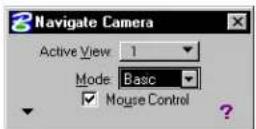
- If you want to use the mouse as well as the keyboard to control the camera, turn on Mouse Control. If Mouse Control is off, all settings pertaining to the mouse are disabled (dimmed).
- (Optional) — Click the Show Shortcuts keys (?) button for a list of the default keyboard and mouse navigation settings.
- (Optional) — To display more settings, click the Show Settings button.
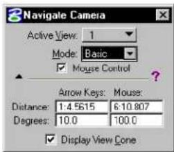
text_image
3 Navigate Camera Active View: 1 Mode: Basic ✓ Mouse Control Arrow Keys: Mouse: Distance: 1:4.5615 6:10.807 Degrees: 10.0 100.0 ✓ Display View Cone-
(Optional) — In the Distance field, enter the distance for each movement of the camera.
Distance is in Working Units. -
(Optional) — In the Degree field, enter the angle for
each movement of the camera.
-
(Optional) — Turn on Display View Cone.
-
Press any of the arrow keys, letter keys, or keyboard combinations to move the camera through the active view.
or
If you are using the mouse, enter a data point to select the active view, then move the mouse to move the camera. Enter another data point to accept and stop moving the camera, or Reset to restore the view's starting position.

When using View Previous and View Next, only mouse accept points are recognized as viewing operations. For example, if in a view you Tilt the camera with the mouse, accept and then Walk forward using the keyboard, when you click the View Previous view control, the keyboard input is ignored, and the view is restored to its condition before the Tilt operation.

To move the camera through a view window using the Advanced Mode
-
Select the Navigate Camera view control.
-
From the Active View option menu, select a view.
-
Set Modeto Advanced.
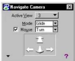
text_image
3 Navigate Camera Active View 3 Mode: Glide ✓ Mouse: TurnWhen you choose the Advanced Mode, you also need to select a navigation option, such as Fly.
-
If you want to use the mouse as well as the keyboard to control the camera, turn on Mouse, and select a navigation option. If Mouse is off, all settings pertaining to the mouse are disabled (dimmed).
-
(Optional) — Click the Show Shortcuts keys (?) button for a list of
the current keyboard and mouse navigation settings.
- (Optional) — To display more settings and navigation options, click the Show Settings button.
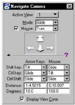
text_image
3 Navigate Camera Active View: 1 Mode: Glide ✓ Mouse: Turn Arrow Keys: Mouse: Shift key: Tilt Glide Ctrl key: Glide Tilt Ctrl Shift: Slide Slide Distance: 1:4.5615 6:10.007 Degrees: 10.0 100.0 ✓ Display View Cone-
(Optional) — For each of the Shift key, Ctrl key, and Ctrl-Shift combo boxes, select a navigation option.
-
(Optional) — In the Distance field, enter the distance for each movement of the camera.
Distance is in Working Units.
-
(Optional) — In the Degree field, enter the angle for each movement of the camera.
-
(Optional) — Turn on Display View Cone.
-
Press any of the arrow keys, letter keys, or keyboard combinations to move the camera through the active view.
or If you are using the mouse, enter a data point to select the active view, then move the mouse to move the camera. Enter another data point to accept and stop moving the camera, or Reset to restore the view's starting position.

When using View Previous and View Next, only mouse accept points are recognized as viewing operations. For example, if in a view you Tilt the camera with the mouse, accept and then Walk
forward using the keyboard, when you click the View Previous view control, the keyboard input is ignored, and the view is restored to its condition before the Tilt operation.
Key-in: CAMERA NAVIGATE
Apply Clip VolumeToView

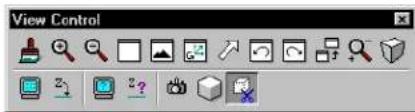
text_image
View ControlUsed to limit the displayed volume for a view. This is useful for working within a limited volume of a design without being hindered by geometry outside the volume of interest. When a clip volume is applied to a view, only elements that are located within the clip volume will display, or can be snapped to, in that view.
Other operations, such as view rotation, fence processing, hidden line removal, and rendering, also honor the clip volume. They ignore any elements that are not displayed within the defined volume for the view.
Clipping elements may consist of any solid or closed extrusion, cylinders, or closed planar elements (shapes, circles, ellipses, complex shapes, grouped holes). Where a planar element is chosen, the clipping volume is generated by sweeping the planar element through the entire design. Planar elements may be selected in any view, because the sweep direction is orthogonal to the plane of the element.
If you later modify a planar element that was used to apply a clip volume, then the clip volume is modified also. If you delete the element used to apply a clip volume, then the clipping is removed also.
Once a clip volume has been applied to a view, you can switch it on and off via the Clip Volume check box in the View Attributes dialog box (Settings > View Attributes).
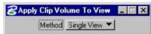
| Tool Setting | Effect |
| Method Sets the views that are to have the clip volume applied. All Views—Applies the clip volume to all currently open views.Single View—Applies the clip volume only to the view in which the clipping element is accepted.That is, you can identify the clipping element in any view and then accept it in the view to which you want clipping applied. | |
To apply a clip volume to a single view
- Place an element to be used as the clipping element.
- Select the Apply Clip Volume To View view control.
- In the tool settings, set Method to Single View.
- Identify the clipping element.
- Accept the clipping element in the view to which you want clipping applied.
Before applying a clip volume, the view is crowd making the stairwell hard to discern.
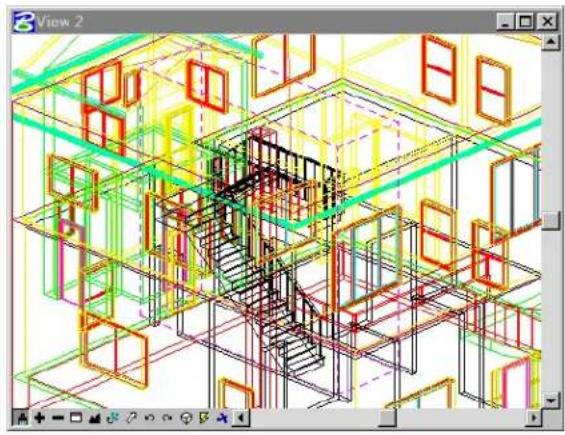
natural_image
3D architectural wireframe model of a building interior with colored structural elements (no text or symbols)After applying a clip volume, the stairwell is clearly seen.
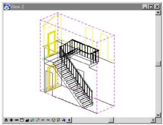
natural_image
Isometric architectural diagram of a multi-level staircase inside a room, shown in isometric view with no text or symbols.Key-in: VIEW CLIP [ICON | SINGLE | ALL]
3D Elements
Many of the elements used in 3D modeling, including shapes, circles, polygons, and arcs, are 2D. That is, they are planar and are therefore restricted to being constructed in one plane, even in a 3D model. 3D elements do not have this restriction,
and can be drawn freely in the design cube.
Open 3D elements
Open elements do not enclose an area or volume.
Non-planar line strings and curves
To place a line string or point curve that is not constrained to one plane, use these tools in the Linear Elements tool box:
| To place a non-planar | Uset histoolintheLinear Elements tool box |
| Line string | PlaceSmartLine(see page 2-17) |
| Point curve Place Point | or Stream Curve (see page 2-29) with the tool setting Non-planar turned on |

The Extract Iso-parametric Lines tool (see page 7-99) in the Create Curves tool box (see page 7-74) and the Extract Face or Edge Geometry tool (see page 8-154) in the 3D Utility tool box (see page 8-144) are used to extract a curve from a B-spline surface, or SmartSolid.
Helixes
A helix is placed with the Place Helix tool (see page 7-95).
3D Primitives
Primitive ^1 surfaces/solids (often referred to by 3D modelers as “primary” or “simple” surfaces/solids) include the 3D objects that are relatively simple to describe.
They are placed in the model with the tools in the 3D Primitives tool box (see page 8-82), which is in the top-left position in the 3D Main tool frame.
Slab
A slab (also referred to as a "3D block") is placed with the Place Slab tool (see page 8-83).
Slab

A slab is defined in the model as an extruded surface in which the profile element is a block (rectangle). For information about generating more complex extruded surfaces, see “Extruded surfaces and surfaces of revolution” on page 8-55.
Sphere
A sphere's geometry is defined by its center and its radius. It is placed in the model with the Place Sphere tool (see page 8-87).
Sphere
Rendered sphere


A sphere is defined in the model as a surface of revolution in which the profile element is an arc. For information about generating more complex surfaces of revolution, see “Extruded surfaces and surfaces of revolution” on page 8-55.
Cone and cylinder
The ends of a cone are two circles lying in parallel planes. It is placed in the model with the Place Cone tool (see page 8-93).
Cone
A cylinder is a cone in which both ends have the same diameter. It is placed in the model with the Place Cylinder tool (see page 8-89).
Torus
A torus (also referred to as a "donut") is defined by its radii
8-54 MicroStation User Guide
and Projection Angle. It is placed in the model with the Place Torus tool (see page 8-94).
Torus
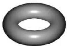
A torus is defined in the model as a surface of revolution in which the profile element is circle.
Wedge
A wedge is placed in the model with the Place Wedge tool (see page 8-98).
Wedge
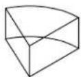

A wedge is defined in the model as a surface of revolution in which the profile element is a rectangle.
Extruded surfaces and surfaces of revolution
Many objects can be drawn by first drawing a planar profile element (or cross-section) and then extruding or revolving the profile.
- An extruded surface or solid is formed by extruding a planar element — line string, curve, shape, ellipse, B-spline curve, complex chain, or complex shape. It is placed in the model with the Extrude tool (see page 8-101) in the 3D Construct tool box.
- A surface or solid of revolution is formed by revolving a planar element about an axis. It is placed in the model with the Construct Revolution tool (see page 8-107) in the 3D Construct tool box.
Extruded surface
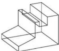
Surface of revolution
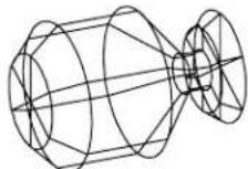
Complex chains and shapes can be extruded or rotated to create elaborate surfaces.
Free-form (NURBS) surfaces
A non-uniform rational B-spline (NURBS) surface is the most mathematically flexible way to represent a surface in a model. A B-spline surface is easy to modify because each pole of its control net affects the shape of the surface only over a limited part. The control net is analogous to a B-spline curve's control polygon.
B-spline surface: wireframe view.
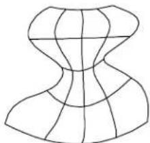
natural_image
Abstract geometric line drawing with intersecting curved and straight lines forming a symmetrical shape (no text or symbols)B-spline surface: smooth shaded view.
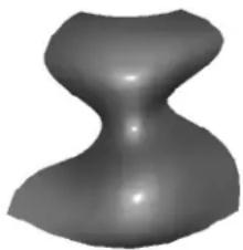
natural_image
Abstract 3D shape resembling a symmetrical, hourglass-like form with smooth shading (no text or symbols)Teapot created using B-spline surfaces.
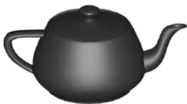
natural_image
Black 3D illustration of a teapot with lid and spout (no text or symbols)
Before working with 3D NURBS surfaces, it is a good idea to become familiar with 2D B-spline concepts and placement. For more information, see “Using Curves” on page 7-59.
3D Fillets
Tools in the 3D Modify tool box (see page 8-118) and the Fillet Surfaces tool box (see page 8-202) let you round edges of solids/surfaces and blend existing surfaces, using a variety of fillets.
Drawing in 3D
By default, data points in a 3D model are placed at the view's Active Depth (see page 8-5). Where you snap a tentative point or place a data point in a blank part of a view, it will be located at the active depth. You can, however, snap a tentative point to an existing element at any depth in a view. When you accept such tentative points, the data point is placed at the level of the snap point.
- AccuDraw and its drawing plane, 3D data points and 3D tentative points (see page 8-65), and 3D auxiliary coordinate systems (see page 8-66), let you place elements away from the Active Depth. Often this improves productivity, since you need not constantly change the Active Depth.
- Boresite Lock makes Identifying existing elements (see page 8-74) easier, by letting you snap to elements that are not near the active depth of the view. When Boresite Lock is off, you can snap to only those elements that are lying on or near the active depth for the view.
Placing elements in 3D
Placing elements in a 2D model is like manual drafting — all elements appear on the same plane, the sheet of paper.
In 3D, you place elements in space — horizontally (for example, a floor), vertically (for example, a wall), or at any other angle or direction (for example, a sloping roof).
Many elements rely on the orientation of the view, AccuDraw's drawing plane, or the current auxiliary coordinate system if the ACS Plane Lock is on, for exact placement. To place elements such as blocks (rectangles), circles (by center), polygons, cells, and text, you have these choices:
- Rotate a view so that the plane of the view (your screen) is parallel to the required orientation.
- Use AccuDraw (see page 8-59) or work with 3D auxiliary coordinate systems (see page 8-66).
Specifying whether an element encloses volume
When you use tools in the 3D Primitives tool box (see page 8-82), the Type tool setting specifies whether the 3D element is either of the following:
- Solid — capped on its ends; encloses a volume.
- Surface — not capped on its ends; does not enclose volume.
For example, to draw a tube you can use the Place Cylinder (see page 8-89) tool with Type set to Surface, while to draw an iron bar you could use the Place Cylinder tool with Type set to Solid.
Top: Sol ids with hidden lines removed. Bottom: Surfaces with hidden lines removed.
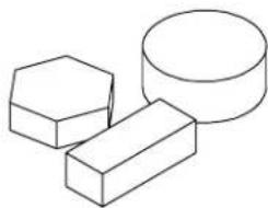
natural_image
Line drawing of three geometric shapes: hexagon, cuboid, and rectangular prism (no text or symbols)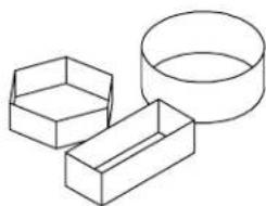
natural_image
Line drawing of three geometric shapes: a hexagonal prism, a rectangular prism, and a circular ring (no text or symbols)Where you have a 3D object that is a surface, you can convert it to a solid, and vice-versa.
To change an element from a surface to a solid
- In the Modify Surfaces tool box, select the Convert 3D tool.
- From the Convert To option menu, choose Solid.
- Identify the element to modify.
- Accept the modification.
Using AccuDraw in 3D
In 3D, usually it is easier to visualize your model in a pictorial view, such as Isometric. AccuDraw gives you the option of working in a pictorial view, while placing elements as if you were working
in the standard, orthogonal views. This is possible because AccuDraw automatically constrains data points to its drawing plane regardless of the active view's orientation.
Compass tilted over to align with the top view plane in a 3D pictorial view.

natural_image
Pure geometric lines forming a diagonal line with intersecting and perpendicular segments (no text or symbols)The Accu Draw window 3D
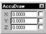
In 3D, when using Rectangular coordinates, the AccuDraw window has an additional field for the z-axis. For Polar coordinates in 3D, the AccuDraw window has the same two fields as in 2D.
Orienting the drawing plane in 3D
Learning to orient AccuDraw's drawing plane is essential to mastering 3D drawing. For example, it is easy with AccuDraw, using an Isometric view, to place a non-planar complex chain or complex shape in any direction without reverting to an orthogonal view. That is, simply by rotating the drawing plane axes to Front, Top, or Side, you can work in an Isometric view while drawing in the plane of any of the orthogonal views.
This is most apparent during the creation of a true 3D drawing normally portrayed as an isometric drawing — for example, a plumbing riser diagram. By starting a pipe run along one view axis and shifting it using the F , S , and T (Front, Side, and Top) keyboard shortcuts, you can twist and turn the pipe through 3D space.
A simple plumbing riser diagram under construction showing the compass at each corner and annotation pointing outthe drawing plane orientation at each vertex.
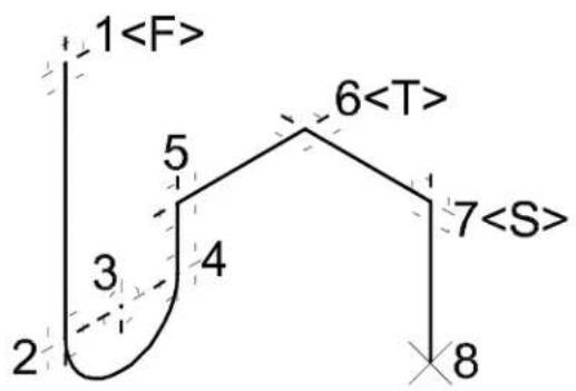
text_image
1This ability to adhere to the standard view axes while manipulating your drawing in a pictorial view is so important that AccuDraw maintains the current orientation from tool to tool. You can still return to the view orientation by using the V (View) keyboard shortcut.
The following table summarizes the AccuDraw keyboard shortcuts available for fine tuning the drawing plane orientation so the axes align in the directions you want them:
| Key | Effect |
| V | Rotates the drawing plane to align with the view axes. |
| F | Rotates the drawing plane to align with the axes in a standard Front view. |
| S | Rotates the drawing plane to align with the axes in a standard Right view. |
| T | Rotates the drawing plane to align with the axes in a standard Top view. |
| R , Q | Used to quickly and temporarily rotate the drawing plane with a single point. |
| R , A | Used to permanently rotate the drawing plane by three points. Because it rotates the active ACS, this rotation will still be active after the tool in use is exited. If on, the tool setting Use Current Origin causes the drawing plane origin to be used as the x-axis origin, thereby eliminating the need to enter an extra data point. Of course, in many cases it is desirable to be able to define the x-axis origin at a different location than the drawing plane origin. |
| R , X | Rotates the drawing plane 90 about its x-axis. |
| R , Y | Rotates the drawing plane 90 about its y-axis. |
| R , Z | Rotates the drawing plane 90° about its z-axis. |
| E | Successively pressing E rotates the drawing plane first 90° about its x-axis, then 90° about its y-axis, and then back to its original rotation. This is useful for working with any drawing plane orientation, particularly where the model is rotated relative to the drawing file axes. |
Arbitrary rotations
By default, AccuDraw orients the drawing plane to the view axes. This is in keeping with the way it works in 2D. You can return AccuDraw to this orientation at any time using the V keyboard shortcut.
You can set up an arbitrary orientation that can be saved and subsequently retrieved as an auxiliary coordinate system (ACS).
To rotate the drawing plane axes to align with the current view
- With the focus in the AccuDraw window, press the V key.
To interactively rotate the drawing plane axes
- With the focus in the AccuDraw window, press R , A .
- Enter a data point to locate the x-axis origin.
- Enter a data point to define the direction of the x-axis.
As a result, the plane of the y-axis relative to the x-axis is implied (perpendicular to the x-axis). All that remains, is to define the direction of the y-axis in that plane.
- Enter a data point to define the direction of the y-axis about the x-axis.
Graphically rotating the drawing plane axes. Left: Defining the x-axis direction. Right: Defining the y-axis direction (only necessary in 3D).
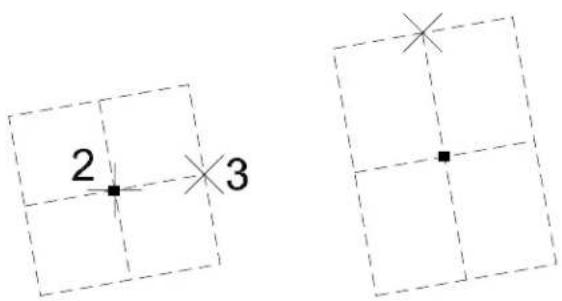
text_image
2 3
For information about saving and retrieving an ACS defined using AccuDraw, see "Using AccuDraw with auxiliary coordinate systems" on page 8-69.
The Front, Side and Toprotations
Three keyboard shortcuts, F , S , and T , are used to orient AccuDraw's drawing plane to the standard Top, Front, and Side views, no matter in what view you are working. Activating one of these shortcuts dynamically rotates AccuDraw's compass to indicate the orientation of the drawing plane.
To rotate the drawing plane axes to align with the standard Top, Front, or Side (Right) view
- With the focus in the AccuDraw window, press the T , F , or S key to rotate the drawing plane to align with the Top, Front, or Side (Right) view, respectively.
Rotating 90 about a specified axis
When the drawing plane is rotated to orientations other than the standard Top, Front, and side, often it is useful to be able to access planes at 90^ to the current orientation. AccuDraw has keyboard shortcuts that rotate the drawing plane 90^ about its individual axes. These shortcuts — R , X or R , Y or R , Z — can be used to spin the drawing plane through 90^ about the selected axis, any number of times, until its orientation is exactly as you desire.
To rotate the drawing plane axes 90 about an individual axis
- With the focus in the AccuDraw window, use one of the following keyboard shortcuts.
| To rotate 90°about | Press |
| x-axis | R , X |
| y-axis | R , Y |
| z-axis | R , Z |
The new orientation is maintained only until a data point or Reset is entered. However, you can save this coordinate system for subsequent recall (see "Using AccuDraw with auxiliary coordinate systems" on page 8-69).
Precision input key-ins in 3D
Precision input key-ins in 3D work much as in 2D, except that
the depth coordinate must also be entered. ^2
For more information about precision input key-ins, see "Precision Input Key-ins" on page 3-91 and "Precision input key-ins with an ACS" on page 8-73.
3D data points and 3D tentative points
While not as easy to use as AccuDraw, 3D data points and 3D tentative points also can be used to position points at any depth within the view volume. They are not restricted to the Active Depth but, for simplicity, require at least two views to be open, with different z-axis orientations. To place points with this method you first define the view x,y values and then, in a second view, define the depth (z value) for the point.
To define a 3D point with 3D data points or 3D tentative points
- In a view, position the pointer at the desired x- and y-coordinates.
- To enter a 3D data point, press the 3D Data button. or
To enter a 3D tentative point, press the 3D Tentative button.
A boreline, in the view's z-direction, displays in each view that is not the same z-axis orientation as the view selected in step 1. (If no borelines display, adjust the views so that at least one other view that shows the same part of the model has a different orientation.)
- In one of the other views, position the pointer on the boreline at the desired depth and again press the 3D Data button or 3D Tentative button.
This completes the positioning of the point in the x, y, and z direction.
For information about the assignment of the 3D Data button and the 3D Tentative button on your system, see "Graphical input
with a digitizing tablet" in the QuickStart Guide.
3D auxiliary coordinate systems
An auxiliary coordinate system (ACS) is a coordinate system with an orientation and, usually, an origin, different from those of the DGN file coordinates. Although not exclusively a 3D concept, an ACS is most useful in 3D modeling as a drawing aid.
By using an ACS that corresponds to the location and orientation of a particular element, you can enter data points relative to parts of the model rather than the global origin.
Although using ACSs may seem complicated, AccuDraw uses them as a basic part of its 3D functionality, permanently storing arbitrary rotations. It is not necessary to learn much about ACSs to use them effectively with AccuDraw.

ACS is called UCS (user coordinate system) by some other CAD systems.
ACS Type
You can choose from these ACS types: Rectangular, Cylindrical, and Spherical.
Rectangular
Like the design cube coordinate system, with coordinates expressed in the form (X,Y,Z). You can use AccuDraw to define, save, and retrieve rectangular ACSs (see "Using AccuDraw with auxiliary coordinate systems" on page 8-69).
Rectangular ACS
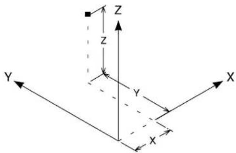
text_image
Z Z Y X XCylindrical
Points are specified as two magnitudes (R and Z) and an angle (q), with coordinates expressed in the form (R, q, Z).
The process of locating a point in a cylindrical ACS can be thought of as follows:
- Moving from the origin along the x-axis a distance of R.
- Rotating about the z-axis an angle of q.
- Finally, moving parallel to the z-axis a distance of Z.
Cylindrical ACS
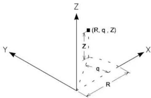
text_image
Z ■(R, q, Z) Z₁ q R Y X
In 2D, there is no depth (z-axis), and cylindrical coordinates are commonly known as polar coordinates. These are used to position a data point with a Cylindrical ACS:
- AX=R,Q,Z for an exact location, where: R is the distance from the origin, along the x-axis. Q is the angle counterclockwise from the x-axis about the z-axis. Z is the distance in the z-direction.
- AD=△R,△Q, Z△ for locations relative to a tentative point, where: △R is the difference in distance from the origin, along the x-axis. △Q is the difference in the angle counterclockwise from the x-axis. △Z is the difference in the distance in the z-direction.
Spherical
(3D only) Points are specified by a magnitude (R) and two angles (q and f), with coordinates expressed in the form (R, q, f).
The process of locating a point in a spherical ACS can be thought of as follows:
- Move from the origin along the x-axis a distance of R to establish a radius vector.
- Rotate this vector about the z-axis an angle of q.
- The angle f is the angle between the radius vector and the positive z-axis.
Spherical ACS
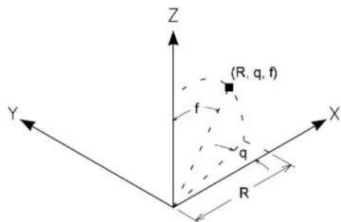
text_image
Z (R, q, f) f q R Y XThese key-ins are used to position a data point with a Spherical ACS:
- AX=R,Q,F for an exact location, where: R is the radius vector distance from the origin. Q is the angle counterclockwise from the x-axis about the z-axis. F is the angle between the radius vector and the z-axis.
- AD=△R,△Q, F△ for locations relative to a tentative point, where: △R is the difference in the radius vector distance from the origin. △Q is the difference in the angle, counterclockwise, from the x-axis. △F is the difference in the angle between the radius vector and the z-axis.
Using AccuDraw with auxiliary coordinate systems
Unless you are using one of the four (Top, right Side, Front, View) standard orientations, AccuDraw “forgets” the drawing plane orientation at the end of the current design session. To overcome this, there is a mechanism to save and retrieve arbitrary drawing plane orientations as rectangular auxiliary coordinate systems.
The R , A keyboard shortcut is used to define an arbitrary drawing
plane orientation that can subsequently be saved as a rectangular ACS. See "Arbitrary rotations" on page 8-62.
To save a drawing plane coordinate system
- With the focus in the AccuDraw window, press W , A . The Write To ACS dialog box opens.

-
In the Name field, key in a name for the coordinate system. or To save the coordinate system as the active (unnamed) ACS, leave the Name field blank.
-
Click the OK button.
To recall a saved drawing plane coordinate system
- With the focus in the AccuDraw window, press G , A . The Get ACS dialog box opens. Where more than one ACS has been saved, the Name field is an option menu from which you can select the required ACS.
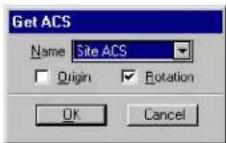
- From the Name option menu, choose the auxiliary coordinate system to recall.
- (Optional) — To rotate the drawing plane to the saved orientation without moving the drawing plane origin, turn off Origin. or To move the drawing plane origin to the saved location without
rotating the drawing plane, turn off Rotation.
- Click the OK button.
The compass updates to show the effect of recalling the saved coordinate system.
Other ways of working with auxiliary coordinate systems
In addition to the AccuDraw keyboard shortcuts for working with an ACS, MicroStation also has an ACS tool box and dialog box. These are the only mechanisms for working with a cylindrical or spherical ACS.
Defining an ACS
You can define an ACS (without using AccuDraw) in any of the following ways:
| To define an ACS | Use this tdo in the ACS tool box |
| That is aligned with a planar element. |  Define ACS (Aligned with Element)(see page 7-139) Define ACS (Aligned with Element)(see page 7-139) |
| By entering data points. |  Define ACS (By Points) (see page 7-1 Define ACS (By Points) (see page 7-1 |
| That is aligned with a view. |  Define ACS (Aligned with View) (se page 7-141) Define ACS (Aligned with View) (se page 7-141) |
Making an ACS active
MicroStation lets you define and save multiple ACSs. At any time, you can make one ACS active. This lets you work simultaneously with three coordinate systems — the active ACS as well as the
DGN file and view coordinate systems.
To make a saved ACS the active ACS (without using AccuDraw)
- From the Utilities menu, choose Auxiliary Coordinates. The Auxiliary Coordinate Systems dialog box opens.
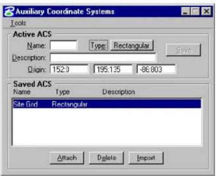
text_image
Auxiliary Coordinate Systems Tools Active ACS Name: Type Rectangular Description: Origin: 152.0 195.135 -86.803 Saved ACS Name Type Description Site Grid Rectangular Attach Delete Import- Select an ACS from the list of saved ACSs.
- Click the Attach button.
The selected ACS becomes the active ACS.
To identify an ACS to make it the active ACS
- In the ACS tool box, select the Select ACS tool (see page 7-144).
Triads appear, indicating the available saved ACSs, in each view that contains the ACS's origins. - Identify the required ACS at its origin.
ACS Plane Lock
If on, ACS Plane Lock sets the default view depth to be on the active ACS's xy plane rather than the view's active depth plane. As with the standard active depth, you can override this
default by snapping to an existing element.
Precision input key-ins with an ACS
While an ACS is active, precision input can be specified as one of the following:
| For precision input | as ACS Type Key in | |
| ACS coordinate Rectangular Spherical Cylindrical | lar | AX==x=value,=y=value,=z=value |
| AX=R=value,=q=angle,=f=angle | ||
| AX=R=value,=q=angle,=Z=value | ||
| Distances, along the ACS axes, from the most recently entered tentative point or data point | Rectangular Spherical Cylindrical | AD=x=value,=y=value,=z=value(x,y,a nd z,axes)AD=R=value,=q=angle,=f=angle |
| AD=R=value,=q=angle,=Z=value | ||
Manipulating an ACS
You can manipulate an ACS as follows:
| To | Use this tool in the ACS tool box |
| Rotate the active ACS. |  Rotate=Active=ACS=(see page 7-142) Rotate=Active=ACS=(see page 7-142) |
| Move the origin of the active ACS. |  Move=ACS=(see page 7-143) Move=ACS=(see page 7-143) |
Manipulating and modifying elements in 3D
For the most part, manipulating and modifying elements in 3D is similar to 2D. 3D-specific aspects are discussed here.
MicroStation=User=Guide=8-73
Element manipulations (for example, scaling or rotation) are performed relative to AccuDraw's drawing plane. If AccuDraw is not active, the manipulation is performed relative to the view axes (see "View coordinates" on page 8-10).
Graphic groups work as they do in 2D.
Selecting elements in 3D
Most basic 3D element manipulations, including moving, scaling, rotating, deleting, and copying, can be done with the Element Selection tool, and are similar to 2D. For example, you can select one or more elements and manipulate them as a single entity (see "Selecting Elements" on page 4-1).
Identifying existing elements
When Boresite Lock is on, you can use a data point to select or identify elements at any depth in a view.
This is important to remember, particularly if AccuDraw is not active. In these cases, when you are using tools such as Move Element or Copy Element, elements identified with a data point only, remain at their depth in the view, regardless of the Active Depth (see page 8-5). Alternatively, if you snap to the element with a tentative point (either manually, or automatically via AccuSnap), and then accept with a data point, the element moves to the Active Depth. When AccuDraw is active, it always controls the depth of the element in the view, keeping it at the same depth by default.
When Boresite Lock is off, only elements at or very near the Active Depth can be selected or identified with a data point.

If you have difficulty selecting an element, check Boresite Lock, as well as Grid Lock and Level Lock in the Reference Guide.
Tentative points and Boresite Lock
Tentative snap points override Boresite Lock. You can snap to elements at any depth in a view, whether or not Boresite Lock is on.
Using the fence in 3D
When you place the fence in a 3D file, it is planar and parallel to the view in which it is placed. The fence encloses the volume bounded by the area of the fence and the view's Display Depth — that is, the volume enclosed by moving the fence from the front to the rear of the view volume along the view z-axis.
Even if an element is completely within the fence boundaries, if it also intersects the view's front or back clipping plane (see "View volume" on page 8-3), it is considered to cross the fence and is clipped if Fence Mode is set to Clip.
This is important to remember, in particular, when creating 3D cells (see page 8-216).
How elements such as shapes and solids are clipped by a fence is affected by the preference Use Optimized Fence Clipping. For more information about how elements such as shapes and solids are clipped by a fence are affected by Use Optimized Fence Clipping, see “Use Optimized Fence Clipping” in the Reference Guide.
Text cannot be clipped.
For basic information about fences, see "Using the Fence to Manipulate and Modify Elements" on page 3-80.
SmartSolids/SmartSurfaces
Using MicroStation's SmartSolids and SmartSurfaces tools you can quickly construct complex 3D models of your designs. For example,
starting with basic solids or surfaces, you then can:
- Add finishing touches, such as fillets and chamfers.
- Use a planar closed shape, or open element, as a profile to create a cut out in either a surface or a solid.
- Use the Shell Solid tool (see page 8-113) to quickly create a "hollow" solid with defined wall thickness.
Settings that affect SmartSolids/SmartSurfaces
Several settings control the way in which SmartSolids and SmartSurfaces are treated. These control both the display and the method for selecting SmartSolids and SmartSurfaces, as well how they are treated when exported as visible edges.
B-spline and 3D dialog box
The B-spline and 3D dialog box (Element menu > B-spline and 3D) controls the default display of SmartSolid/SmartSurface elements, as well as B-spline curves and surfaces.
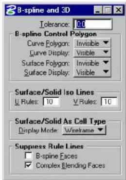
text_image
B-spline and 3D Tolerance: 0.0 B-spline Control Polygon Curve Polygon: Invisible Curve Display: Visible Surface Polygon: Invisible Surface Display: Visible Surface/Solid Iso Lines Rules: 10 Rules: 10 Surface/Solid As Cell Type Display Mode: Wireframe Suppress Rule Lines B-spine Faces Complex Blending FacesDisplay
By default, SmartSolids and SmartSurfaces are displayed in Wireframe display mode. This is the more efficient mode for working with SmartSolids and SmartSurfaces in a design session. Surfaces display mode should be used only where the model is to be rendered with an earlier version of MicroStation (pre MicroStation/J).
Surface/Solid Iso Lines
In Wireframe (and Surfaces) display mode, curved surfaces are represented both by their edge lines and a defined number of iso lines. The iso lines provide a visual indication of a surface's curvature.
With the default setting of 4, for example, a full cylindrical solid is displayed with 4 surface rule lines, while the same solid cut in half displays with 2 surface rule lines. Planar surfaces, which do not have curvature, are represented by their edge boundaries only.
To change the default display of SmartSolids and SmartSurfaces
- From the Element menu, choose B-spline and 3D.
The B-spline and 3D dialog box opens.
- Make the desired changes to the settings.
In non-rendered views, curved surfaces are represented by iso lines. Top: Surface/Solid Iso Lines set to 4 (the default). Bottom: Surface/Solid Iso Lines set to 10.
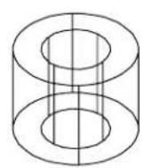
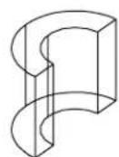
natural_image
Abstract line drawing of a stylized flower or butterfly shape with no text or symbols
natural_image
Abstract wavy surface diagram with grid lines and an oval highlight (no text or symbols)Locate By Face
This setting, in the Input category of the Preferences dialog box, affects the way that solids and closed elements are selected. Generally, you select elements by snapping to their edges. When Locate By Face is on, a data point anywhere on a solid or surface will select that face element. This is particularly useful in a rendered view, where you can identify a solid or surface with a data point anywhere on the displayed surface.
Options for Locate By Face are:
- Never — in all views, solids and surfaces can be identified only with a data point on an edge or surface rule line.
- Rendered Views Only (default) — where a view's default display mode is set to any of the rendering options, surfaces and solids may be identified with a data point anywhere on their surface, not necessarily on an edge line or surface rule line.
• Always — in all views (whether rendered or not) faces may be identified with a data point anywhere on their surface.
To change the method of selecting surfaces
- From the Workspace menu, choose Preferences.
The Preferences dialog box opens. - In the Category list, select Input.
The Set input preferences options display. - From the Locate By Face option menu, choose the required setting.
- Click OK.
With Locate By Face: Off — lids and surfaces can be identified only with a data point on an edge or rule line (for example, 1). On — solids and usfaces may be identified with a data point anywhere on any face (for example, 2).
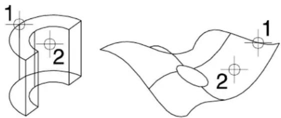
text_image
1 2 1 2Use Optimized Fence Clipping
In the Operation section of the Preferences dialog box, the Optimized Fence Clipping setting affects the way that SmartSolids and SmartSurfaces are clipped. When this option is on (the default), fence operations that involve clipping (Clip and Void Clip) do not drop the solids or surfaces back to their basic components. In effect, the fence operation works like a boolean subtraction, where part of the solid or surface is removed.
As with other fence operations in 3D, the extent of the fence volume is defined by the fence, and the display depth of the view. When a circular fence is used, for example, it is similar to
using a cylinder as the clipping template.
Optimized fence clipping is supported in all views, including camera views.
Using optimized fence clipping. Top: A block with the fence in place ready to delete. Bottom: The result of deleting the fence contents with Optimized Fence Clipping turned off (left) and on (right).
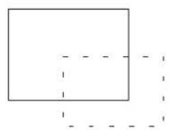
natural_image
Simple geometric diagram with a rectangle and dashed lines forming an L-shape (no text or symbols)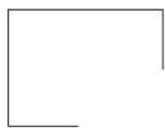
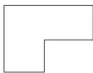
Exporting visible edges
When Exporting Visible Edges, from a model that consists primarily of SmartSolids, the SmartSolids option in the Method menu may prove faster. While processing all element types, it is optimized for SmartSolids.

Calculate Intersections is not supported with the SmartSolids option. Also, for files containing a large number of elements, another option may prove more suitable. You should experiment to determine which option is best for your application.
To choose SmartSolids when exporting visible edges
- From the File menu, choose Export > Visible Edges.
The Export Visible Edges dialog box opens.
- In the General tab, from the Method option menu, choose SmartSolids.
3D Main tool frame
Tools for creating and modifying solids and surfaces are accessed from tool boxes in this tool frame.
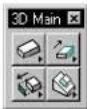
| To | Use tools in the |
| Place a simple 3D element — slab, sphere, cylinder, cone, torus, or wedge. | 3D Primitives tool box (see page 8-82) |
| Extrude a solid or surface, or construct a surface of revolution,orExtrude a solid or surface along a path,orConstruct a thin shell solid,orThicken a surface into a solid. | 3D Construct tool box (see page 8-100) |
| Modify a solid, remove a face, taper a solid orConstruct a new solid from the union, intersection, or difference of existing solids,orCut, fillet, or chamfer an existing solid, or edit a 3D primitive. | 3D Modify tool box (see page 8-118) |
| Align elements relative to a face on each element,orChange the display of a Smart-Solid/SmartSurface,orExtract a face or edge from a solid,or intersect a solid/surface with a linear element.orCreate a set of planar shapes from a 3 De l e m e n t . | 3D Utility tool box (see page 8-144) |
Key-in: DIALOG TOOLBOX 3DTOOLS [OFF | ON | TOGGLE]
3D Primitives tool box
The tools in the 3D Primitives tool box are used to place simple 3D elements — slab, sphere, cylinder, cone, torus, or wedge.
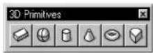
| To | Select in the 3D Primitives tool box |
| Place a slab. |  Place Slab (see page 8-83) Place Slab (see page 8-83) |
| Place a sphere. |  Place Sphere (see page 8-87) Place Sphere (see page 8-87) |
| Place a cylinder. |  Place Cylinder (see page 8-89) Place Cylinder (see page 8-89) |
| Place a cone. |  Place Cone (see page 8-93) Place Cone (see page 8-93) |
| Place a torus. |  Place Torus (see page 8-94) Place Torus (see page 8-94) |
| Place a wedge-shaped object. |  Place Wedge (see page 8-98) Place Wedge (see page 8-98) |
Key-in: DIALOG TOOLBOX 3DDRAWING [OFF | ON | TOGGLE]
Place Slab

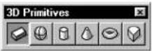
(3D only) Used to place an extruded surface/solid with a rectangular cross-section.
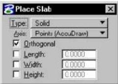
text_image
Place Slab Type: Solid Axis: Points (AccuDraw) Orthogonal Length: 0.0000 Width: 0.0000 Height: 0.0000| Tool Setting | Effect |
| Type | Can be Surface (not capped) or Solid (capped). |
| Axis | Sets the direction in which the height is projected.Points—Direction of height is defined graphically.AccuDraw can be used to define the drawing plane on which the points are placed.Screen X, Y, or Z—Direction of the height is set to the screen's X, Y, or Z axis.Drawing X, Y, or Z—Direction of the height is set to the drawing's, or design file's, X, Y, o |
| Orthogonal | If on, the edges are orthogonal. |
| Length If | on, sets the length (step 3). |
| Width If | on, sets the width (step 4). |
| Height If | on, sets the height (step 5). |
rZ axis.
To place a slab
- Select the Place Slab tool.
- Enter a data point to define the origin.
When Axis is set to Points, a side of the slab is parallel to the view in which this data point is entered.
- Enter a data point to define the length and rotation angle.
If Length is on, this data point defines the rotation angle.
- Enter a data point to define the width.
If Width is on, this data point accepts the width.
- Enter a third data point to define the height.
If Height is on, this data point accepts the height.
If Orthogonal is on, the slab is orthogonal; all adjacent edges are perpendicular to one another.
Place Slab, constrained to be orthogonal Defining the length, width, and height graphically.
text_image
Top 3 1 2
text_image
Isometric
text_image
Front 4
text_image
RightPlacing the same slab as in previous example, but ith length, width, and height constrained using AccuDraw.
text_image
Top 1 L w 2 3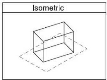
text_image
Isometric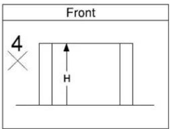
text_image
Front 4 HKey-in: PLACE SLAB ICON

Although the slab's length, width, and height can be specified as tool settings, it is generally quicker and easier to type these distances into the AccuDraw window.

To place an extrusion with a non-rectangular cross-section, use the Extrude tool (see page 8-101) in the 3D Construct tool box.
Place Sphere

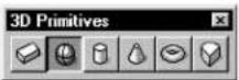
(3D only) Used to place a sphere — a surface/solid of revolution with a circular cross section.
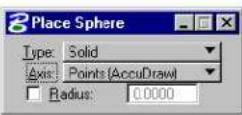
| Tool Setting | Effect |
| Type | Sets the type of sphere placed, Solid or Surface. |
| Axis Sets | the direction of the sphere's axis.Points—Direction of axis is defined graphically.AccuDraw can be used to define the drawing plane on which the points are placed.Screen X, Y, or Z—Direction of the axis is set to the screen's X, Y, or Z axis.Drawing X, Y, or Z—Direction of the axis is set to the drawing's, or design file's, X, Y, o |
| Radius | If on, sets the radius. |
rZ axis.
To place a sphere
- Select the Place Sphere tool.
- Enter a data point to define the sphere's center.
- If Radius is off, enter a data point to define the radius.
If Radius is on, this data point accepts the sphere.
Place Sphere. Defining the radius graphically.
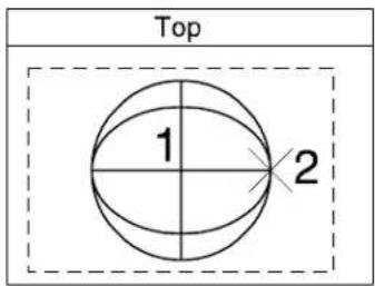
text_image
Top 1 2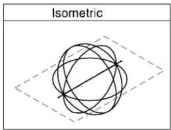
text_image
Isometric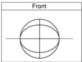
text_image
Front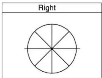
text_image
RightPlacing the same sphere with radius keyed in using AccuDraw.
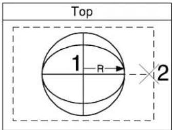
text_image
Top 1 R 2Key-in: PLACE SPHERE ICON

Although the sphere's radius can be specified as a tool setting, it is generally quicker and easier to type the radius into the AccuDraw window.

To place a volume of revolution with a non-circular cross-section, use the Construct Revolution tool (see page 8-107) in the 3D Construct tool box.
Place Cylinder

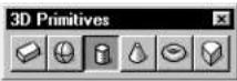
(3D only) Used to place a cylinder.
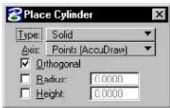
| Tool Setting | Effect |
| Type | Can be Surface (not capped) or Solid (capped). |
| Axis | Sets the direction of the cylinder's axis (height).Points—Direction of height is defined graphically.AccuDraw can be used to define the drawing plane on which the points are placed.Screen X, Y, or Z—Direction of the height is set to the screen's X, Y, or Z axis.Drawing X, Y, or Z—Direction of the height is set to the drawing's, or design file's, X, Y, o |
| Orthogonal | If on, the cylinder is a right cylinder. |
| Radius If | on, sets the radius. |
| Height If | on, sets the height. |
rZ axis.
To place a cylinder graphically (no constraints)
- Select the Place Cylinder tool.
- In the tool settings, check that Orthogonal, Radius, and Height, are turned off.
- Enter a data point to define the center of the base.
- Enter a data point to define the radius.
- Enter a data point to define the direction and height.
Place Cylinder with all constraints turned off and all data points entered graphically.
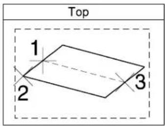
text_image
Top 1 2 3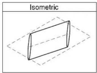
text_image
Isometric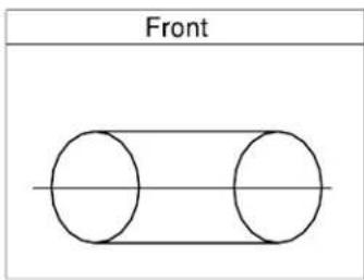
text_image
Front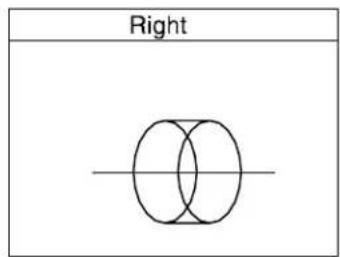
text_image
RightPlace Cylinder with Orthogonal turned on andlla data points entered graphically.
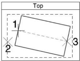
text_image
Top 1 2 3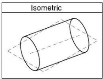
text_image
Isometric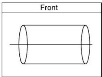
text_image
Front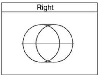
text_image
RightPlace cylinder with orthogonal turned on and AccuDraw used to constrain the radius "R" and height "H."
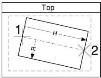
text_image
Top 1 H R 2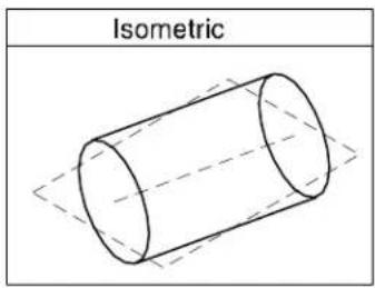
text_image
IsometricKey-in: PLACE CYLINDER ICON
Key-in: PLACE CYLINDER [RADIUS | RIGHT | SKEWED]

Although the cylinder's radius and height can be specified as
8-92 MicroStation User Guide
tool settings, it is generally quicker and easier to type these distances into the AccuDraw window.
Place Cone

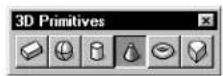
(3D only) Used to place a cone.
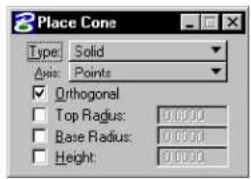
text_image
Place Cone Type: Solid Axis: Points Orthogonal Top Radius: 0.0000 Base Radius: 0.0000 Height: 0.0000| Tool Setting | Effect |
| Type | Can be Surface (not capped) or Solid (capped). |
| Axis | Sets the direction of the cone's axis (height).Points—Direction of height is defined graphically.AccuDraw can be used to define the drawing plane on which the points are placed.Screen X, Y, or Z—Direction of the height is set to the screen's X, Y, or Z axis.Drawing X, Y, or Z—Direction of the height is set to the drawing's, or design file's, X, Y, o |
| Orthogonal | If on, the cone is a right cone. |
| Top Radius | If on, sets the second radius (step 5). |
| Base Radius | If on, sets the first radius (step 3). |
| Height If | on, sets the height. |
To place a cone graphically
- Select the Place Cone tool.
- Enter a data point to define the center of the base.
- Enter a data point to define the base's radius.
- Enter a data point to define the height and the top's center.
If Orthogonal is on, this data point defines the height only. - Enter a data point to define the top radius.
Key-in: PLACE CONEICON
Key-in: PLACE CONE [RADIUS | RIGHT | SKEWED]

Although the cone's radii and height can be specified as tool settings, it is generally quicker and easier to type these distances into the AccuDraw window.

This tool works similarly to the Place Cylinder tool (see page 8-89). See the illustration after the procedure, "To place a cylinder."
Place Torus

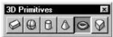
(3D only) Used to place a torus (a donut-shaped surface or solid).
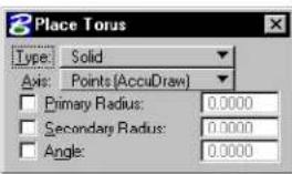
text_image
Place Torus Type: Solid Axis: Points (AccuDraw) Primary Radius: 0.0000 Secondary Radius: 0.0000 Angle: 0.0000| Tool Setting | Effect |
| Type | Can be Surface (not capped) or Solid (capped). |
| Axis | Sets the direction of the axis of revolution.Points—Direction of axis is defined graphically.AccuDraw can be used to define the drawing plane on which the points are placed.Screen X, Y, or Z—Direction of the axis is set to the screen's X, Y, or Z axis.Drawing X, Y, or Z—Direction of the axis is set to the drawing's, or design file's, X, Y, o |
| Primary Radius | If on, sets the primary radius (the one the torus' profile is swept around). |
| Secondary Radius | If on, sets the secondary radius (the radius of the torus' profile). |
| Angle | If on, sets the sweep angle. |
To place a torus
- Select the Place Torus tool.
- Enter a data point to define the start point.
- Enter a data point.
| Primary Radius: | This data point defines: |
| Off | Center, primary radius, and start angle. |
| On Just the center and start angle. | |
- Enter a data point to complete the torus, as follows:
| If these are on: | This data point defines: |
| None3 | Secondary radius and sweep angle. |
| Secondary Radius | Sweep angle. |
| Angle | Secondary radius. |
| Secondary Radius and Angle | Direction of the sweep angle rotation. |
3 The Primary Radius has no effect on this step.
Place Torus with all constraints off.
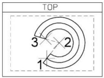
text_image
TOP 3 2 1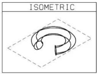
text_image
ISOMETRIC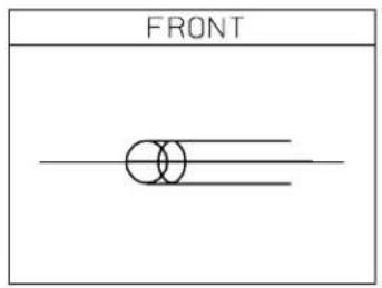
text_image
FRONT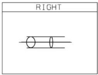
text_image
RIGHTPlacing a torus, with Primary Radius (R1), Secondary Radius (B) and Angle (a) constrained.
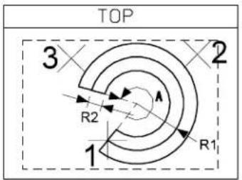
text_image
TOP 3 2 R2 R1 1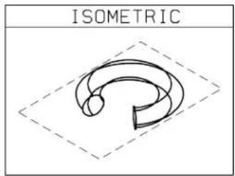
text_image
ISOMETRICKey-in: PLACE TORUS
Place Wedge

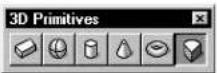
(3D only) Used to place a wedge — a volume of revolution with a rectangular cross-section.
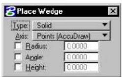
| Tool Setting | Effect |
| Type | Can be Surface (not capped) or Solid (capped). |
| Axis | Sets the direction of the axis of revolution.Points—Direction of axis is defined graphically.AccuDraw can be used to define the drawing plane on which the points are placed.Screen X, Y, or Z—Direction of the axis is set to the screen's X, Y, or Z axis.Drawing X, Y, or Z—Direction of the axis is set to the drawing's, or design file's, X, Y, o |
| Radius If on, sets the primary radius. | |
| Angle If on, sets the angle (of sweep). | |
| Height | If on, sets the height. |
To place a wedge
- Select the Place Wedge tool.
- Enter a data point to define the outside start point.
- Enter a data point to define the center and the start angle.
If Radius is on, this data point defines just the start angle. - Enter a data point to define the sweep angle.
If Angle is on, this data point defines the direction of the rotation. - Enter a data point to define the height.
If Height is on, this data point defines whether the wedge is extruded up or down from the start plane.
Placing a Wedge with all constraints off.
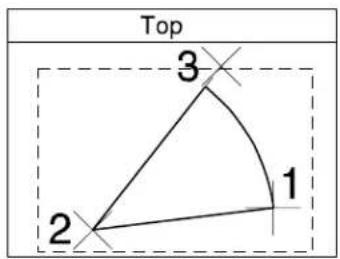
text_image
Top 3 1 2
text_image
Isometric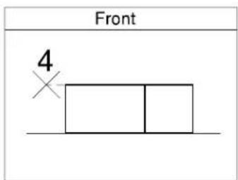
text_image
Front 4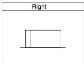
text_image
RightPlacing a Wedge with Primary Radius "R," Angle "A", and Height "H" constrained.
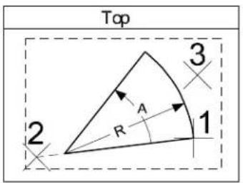
text_image
Top 2 R A 1 3
text_image
Isometric
text_image
Front ×4Key-in: PLACE WEDGE

To place a volume of revolution with a non-rectangular cross-section, use the Construct Revolution (see page 8-107) tool in the 3D Primitives tool box.
3D Construct tool box
Tools in the 3D Construct tool box are used to extrude a surface or solid linearly or along a path, construct a surface or solid of revolution, create a shell solid, or thicken a surface to create a solid.
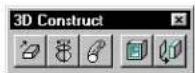
| To | Select in the 3D Construct tool box |
| Create a surface or solid by extruding an element linearly. |  Extrude (see page 8-101) Extrude (see page 8-101) |
| Create a surface or solid by revolving an element. |  Construct Revolution (see page 8-107) Construct Revolution (see page 8-107) |
| Create a surface or solid by extruding an element along a path. |  Extrude Along Path (see page 8-109) Extrude Along Path (see page 8-109) |
| Hollow out a solid to create a solid with walls of constant thickness. |  Shell Solid (see page 8-113) Shell Solid (see page 8-113) |
| Add thickness to a surface to create a solid. |  Thicken to Soil (see page 8-116) Thicken to Soil (see page 8-116) |
Key-in: DIALOG TOOLBOX 3DCONSTRUCT[OFF | ON | TOGGLE]
Extrude

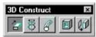
(3D only) Used to create a surface or solid — a complex 3D element generated by linearly extruding a profile element (line, line string, arc, ellipse, text, multi-line, complex chain, complex shape, or B-spline curve) a defined distance. Surfaces formed between the original profile element and its extrusion are indicated by straight lines connecting the keypoints.
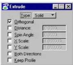
text_image
Extrude Type: Solid Orthogonal Distance: 0.0001 Spin Angle: 0.0001 X Scale: 1.000000 Y Scale: 1.000000 Both Directions Keep Profile| Tool Setting Effect | |
| Type | Can be Surface (not capped) or Solid (capped). |
| Orthogonal If on, the | profile element is extruded orthogonally. |
| Distance | If on, sets the distance, in working units, the element is extruded. |
| Spin Angle If on, sets | the spin angle. |
| X Scale If on, sets | the scale factor in the x-direction. ^1 |
| Y Scale | If on, sets the scale factor in the y-direction. |
| Both Directions | If on, the profile element is extruded in both directions. |
| Keep Profile | If on, the original profile element is kept in the design. |
If X Scale or Y Scale are off, the profile element is not scaled in that direction.
Toextrudeasurfaceorsolid
- Use the Element Selection tool to select the profile element.
- Select the Extrude tool.
- Enter a data point to define the start point.
- Enter a second data point.
| Distance Defines extrusion's |
| Off Distance and direction |
| On Direction |
Alternative method — To extrude a surface or solid
- Select the Extrude tool.
- Identify the profile element.
- Enter a data point.
| Distance Defines extrusion's |
| Off Distance and direction |
| On Direction |
Extruding a solid graphically (with Orthogonal tuned off). Identify the profile (1). Define the distance and direction (2).
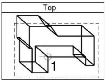
text_image
Top 1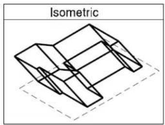
text_image
Isometric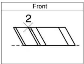
text_image
Front 2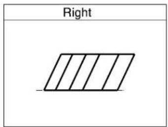
text_image
RightExtruding a solid using AccuDraw to constrain ht extrusion distance (D) and direction (to make the extrusion orthogonal).
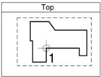
text_image
Top 1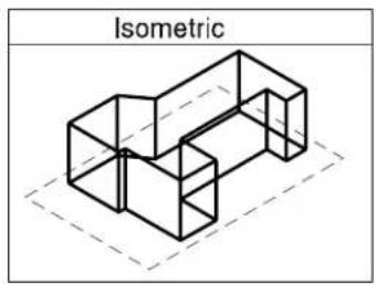
natural_image
Isometric line drawing of a 3D geometric structure with dashed lines indicating hidden edges (no text or symbols)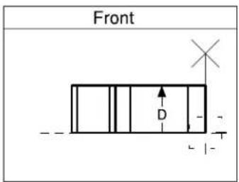
text_image
Front D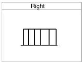
text_image
RightWith Both Directions turned on, the profile is extruded iboth directions by the distance (D).
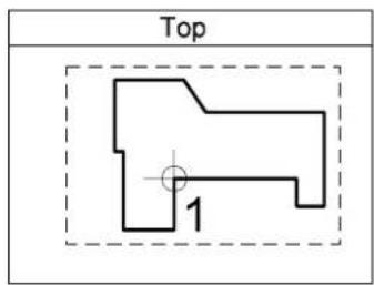
text_image
Top 1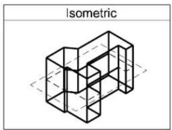
text_image
Isometric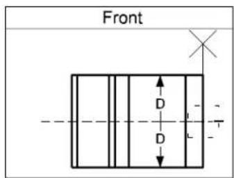
text_image
Front D D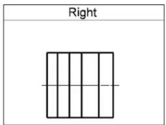
text_image
RightKey-in: CONSTRUCT SURFACE PROJECTION

Although the extrusion distance can be specified as a tool setting, it is generally quicker and easier to type this distance into the AccuDraw window.

The Place Slab tool (see page 8-83) provides a faster way to place an extrusion with a rectangular cross-section. The Place Cylinder tool (see page 8-89) provides a faster way to place an extrusion with a circular cross-section.
Construct Revolution

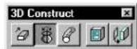
(3D only) Used to create a surface or solid of revolution — a complex 3D element that is generated by rotating a profile element (line, line string, arc, ellipse, shape, complex chain, complex shape, or B-spline curve) about an axis of revolution. Surfaces created by the profile element, as it is rotated, are indicated by arcs connecting the keypoints.
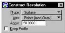
| Tool Setting | Effect |
| Type | Can be Surface (not capped) or Solid (capped). |
| Axis | Sets the direction of the axis of revolution.Points—Direction of axis is defined graphically.AccuDraw can be used to define the drawing plane on which the points are placed.Screen X, Y, or Z—Direction of the axis is set to the screen's X, Y, or Z axis.Drawing X, Y, or Z—Direction of the axis is set to the drawing's, or design file's, X, Y, o |
| Angle Sets the rotation angle. | |
| Keep Profile | If on, the original profile element is kept in the design. |
rZ axis.
To construct a solid or surface of revolution
- Select the Construct Revolution tool.
- Identify the profile element.
- Enter a data point ^3 .
If Axis is set to Points, this data point defines one point on the axis of revolution. Otherwise, this data point defines the axis of revolution.
- If Axis is set to Points, enter a second data point to define another point on the axis of revolution.
- Reset to finish.
Construct
Revolution.
AccuDraw used to constrain the axis of rotation, defined by points 2 and 3.
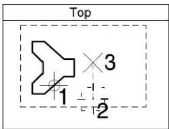
text_image
Top 1 2 3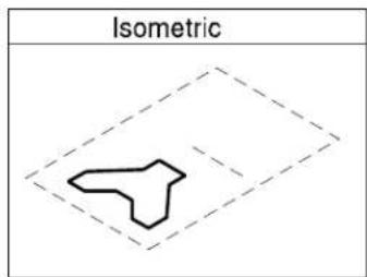
text_image
IsometricThe completed solid (of revolution).
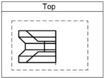
text_image
Top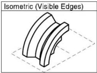
natural_image
Isometric view of a curved mechanical component with dashed alignment lines (no text or symbols)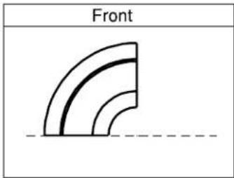
text_image
Front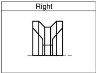
text_image
RightKey-in: CONSTRUCT SURFACE REVOLUTION
Extrude Along Path

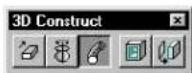
(3D only) Used to create:
- a tubular surface or solid extrusion along a path.
- a surface or solid by extruding a profile element (line, line string, arc, ellipse, complex chain, complex shape, or
B-spline curve) along a path.
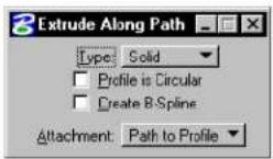
| Tool Setting | Effect |
| Type | Can be Surface (not capped) or Solid (capped). |
| Profile is Circular | If off, the surface/solid is constructed by extruding one element (the profile) along another element (the path). Orientation of the profile changes continually to follow the orientation of the path.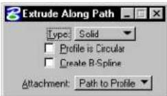 If on, the tool settings expands to display Inside and Outside radius settings for a tube with circular cross-section to be generated. If on, the tool settings expands to display Inside and Outside radius settings for a tube with circular cross-section to be generated.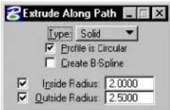 Inside Radius—(If Profile is Circular is on only) If on, sets the inside radius.Outside Radius—(If Profile is Circular is on only) If on, sets the outside radius. Inside Radius—(If Profile is Circular is on only) If on, sets the inside radius.Outside Radius—(If Profile is Circular is on only) If on, sets the outside radius. |
| Create B-Spline | If on, a B-Spline surface or solid is created. |
| Attachment | (If Profile is Circular is off only) Sets the attachment mode for the profile to the path.Path to Profile—The profile is extruded from its current position, following a path defined by the path element.Profile to Path—The profile is attached to the path element and extruded along it. |
To extrude a circular tube along a path
- Select the Extrude Along Path tool.
- In the Tool Settings window, turn on Profile is Circular.
- Identify the path element.
- Accept the path element.
-
If Outside Radius is off, enter a data point to define the outside radius.
or If Outside Radius is on, accept the outside radius. -
If Inside Radius is off, enter a data point to define the inside radius.
or If Inside Radius is on, accept the inside radius.
The extrusion appears.
- Accept to complete the extrusion.
Extrude circular tube along path (with inside rad outside radii turned on). Left: Identify the path (1). Right: Accept to view the extrusion (2), then accept (3) ot complete the extrusion.
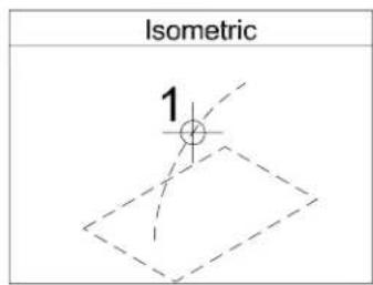
text_image
Isometric 1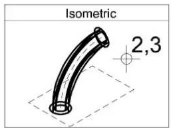
text_image
Isometric 2,3To extrude a profile along a path
- Select the Extrude Along Path tool.
- If necessary, turn off Profile is Circular.
- Set Attachment to the required setting.
-
Identify the path element.
-
Identify the profile element, at the point at which you want the path to be attached to the profile, or the profile to be attached to the path.
-
Accept to view the extrusion
-
Accept to complete the extrusion.
Extrude profile along path. Left: Identify the path (1) and the profile (2). Right: Accept to view the extruded profile (3), then accept (4) to complete the extrusion.
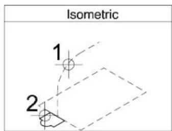
text_image
Isometric 1 2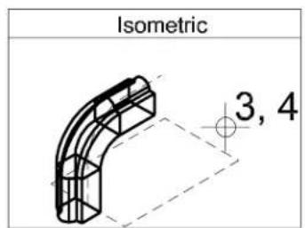
text_image
Isometric 3, 4Key-in: CONSTRUCT EXTRUDE ALONG
Shell Solid

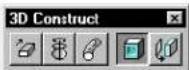
(3D only) Used to create a hollowed out solid having faces of a defined thickness. One or more selected faces may be removed to create an opening. You can shell both standard solids and those that have been modified in some way.
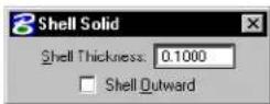
In operation, you can select one or more faces as follows:
• After selecting the solid, as you move the screen pointer over it, the face nearest the pointer highlights. A data point selects the highlighted face, which remains highlighted.
- You can select additional faces using
- To select a face that is behind another in the view, enter a data point (or
- You can use Resets also to deselect an incorrect face. Where a number of faces have been selected, consecutive Resets will deselect them in the reverse order (that is, the last face selected is the first face deselected).
| Tool Setting | Effect |
| Shell Thickness | Sets the wall thickness for the remaining faces. |
| Shell Outward | If on, material is added to the outside; the origin solid defines the inside of the walls. |
To construct a shell solid with no faces removed
- Select the Shell Solid tool.
- In the Shell Thickness field, key in the desired thickness value.
-
If required, turn on Shell Outward.
-
Identify the solid.
The solid highlights. Simultaneously, the face nearest the screen pointer location highlights also.
- Accept, away from the solid, to create the hollowed out shell solid.
To construct a shell solid with one or more faces removed
- Select the Shell Solid tool.
- In the Shell Thickness field, key in the desired thickness value.
- If necessary y, turn on Shell Outward.
-
Identify the solid.
The solid highlights. Simultaneously, the face nearest the screen pointer location highlights also. -
Identify the face to remove (with a data point).
The face highlights. -
Accept, to create the shell solid or Identify further faces for removal (with
data points). -
Accept, to create the shell solid.
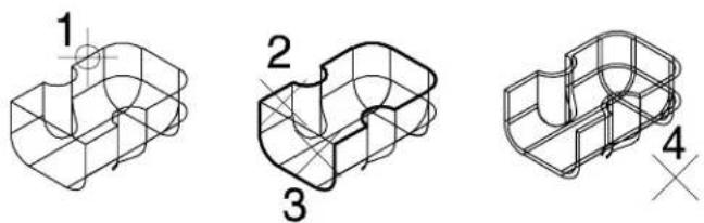
natural_image
Three technical line drawings of a 3D mechanical part with grid lines, showing different cross-sectional views (no text or symbols)Creating a shell solid. Left: Identify the solid (1). Center: Identify the first face to remove with a data point (2) and the second face with a
Rendered view of the shell solid.
natural_image
3D rendered mechanical part with two cylindrical cutouts (no text or symbols)Key-in: CONSTRUCT SHELL
Thicken to Solid

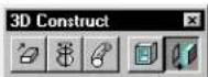
(3D only) Used to add thickness to an existing surface to create a solid. On identifying the surface, an arrow displays showing the distance and direction of the thickening that will be added. If Add To Both Sides is on, arrows display in both directions. If Thickness is not turned on, then thickening is added graphically, with the amount of thickening defined by the screen pointer.
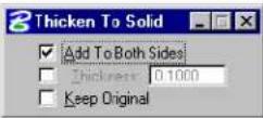
| Tool Setting | Effect |
| Add To Both Sides | If on, the thickness value is added to both sides of the surface. |
| Thickness | Sets the thickness value that is added to the surface. |
| Keep Original | If on, the original profile element is retained. |
Toaddthickness to asurface to create solid
- Select the Thicken to Solid tool.
- Turn on Thickness.
- In the Thickness field, enter the value for the thickening.
- If necessary, turn on Add To Both Sides.
- Identify the surface.
The surface highlights. An arrow(s) displays, showing the distance and to which side(s) the thickness will be added.
-
If Add To Both Sides is off, move the pointer, using the arrows as a guide, to select the side for thickening.
-
Accept.
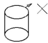
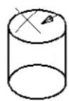
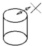
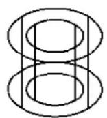
Thickening an existing surface (a cylinder) to create a solid.
Top left, center, and right show the cylinder before applying thickening to the outer, inner, and both sides, respectively. For thickening to either the inner or outer sides of the surface, the direction is defined by the location of the screen pointer and indicated by an arrow. Where Add To Both Sides is selected, the arrows point in both directions and the screen pointer location has no bearing on the direction of thickening. Bottom left, center and right, show the results of the thickening for outer, inner, and both sides, respectively.
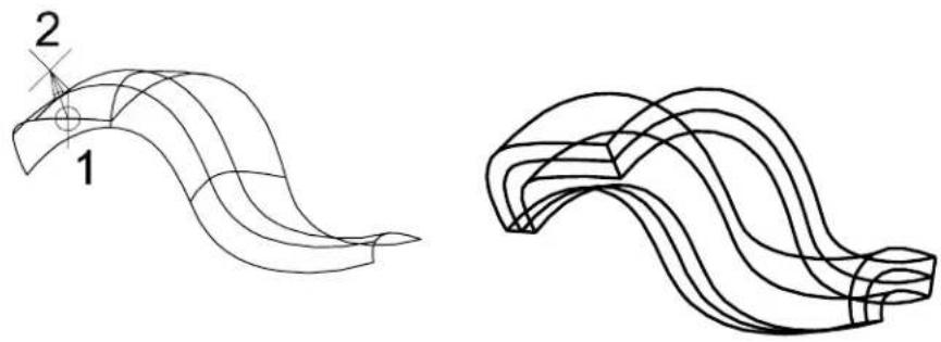
natural_image
Two abstract wavy line drawings labeled 1 and 2, no text or symbols presentB-spline surfaces also may be thickened to solid: Left: Identify the surface (1), define the distance (2) and accept. Right: The resulting solid.
Rendered image showing B-spline surface before (left) and after (right) thickening to a solid.

natural_image
Two abstract wavy metallic surfaces with gradient shading, no text or symbols presentKey-in: CONSTRUCT THICKEN
3D Modify tool box
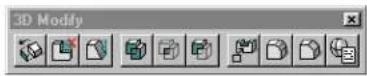
Tools in the 3D Modify tool box are used to:
- modify, taper, or remove faces of a solid.
-
construct a single solid from the union, intersection, or difference of existing solids.
-
place cuts, fillets, or chamfers on existing solids.
- edit existing 3D primitive elements.
| To | Select in the 3D Modify tool box |
| Relocate inwards or outwards one or more faces of a solid. |  Modify Solid (see page 8-120) Modify Solid (see page 8-120) |
| Remove one or more faces from a solid. |  Remove Faces and Heal (see page 8-122) Remove Faces and Heal (see page 8-122) |
| Taper one or more faces of a solid. |  Taper Solid (see page 8-126) Taper Solid (see page 8-126) |
| Construct a single solid that is the union of two or more existing (overlapping) solids. |  Construct Union (see page 8-128) Construct Union (see page 8-128) |
| Construct a single solid that is the intersection of two or more existing (overlapping) solids. |  Construct Intersection (see page 8-130) Construct Intersection (see page 8-130) |
| Construct a single solid by subtracting the volume of one or more (overlapping) solids from another. |  Construct Difference (see page 8-133) Construct Difference (see page 8-133) |
| Create a cut, slot, or pocket in a solid. |  Cut Solid (see page 8-134) Cut Solid (see page 8-134) |
| Fillet one or more edges of a solid. |  Fillet Edges (see page 8-138) Fillet Edges (see page 8-138) |
| Chamfer one or more edges of a solid. |  Chamfer Edges (see page 8-140) Chamfer Edges (see page 8-140) |
| Modify the dimensions of existing 3D primitive elements. |  Edit 3D Primitive (see page 8-143) Edit 3D Primitive (see page 8-143) |
Key-in: DIALOG TOOLBOX 3DMODIFY[OFF | ON | TOGGLE]
Modify Solid

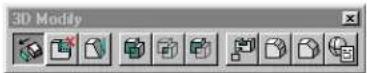
(3D only) Used to relocate a face of a solid inwards (negative) or outwards (positive) relative to the center of the solid. Direction of movement is normal to the selected face. You can select the face for modification as follows:
• After selecting the solid, as you move the screen pointer over it, the face nearest the pointer highlights. A data point selects the highlighted face, which remains highlighted.
• To select a face that is behind another, first enter a data point on the face (in the view), which will highlight the nearest face. Then enter Resets until the required face highlights.
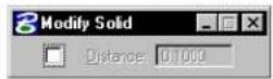
| Tool Setting | Effect |
| Distance | If on, sets the distance that the face is to be modified (moved) relative to the center of the solid. |
▶ Tomodifyafaceofasolidbyasetdistance
- Select the Modify Solid tool.
- Turn on Distance.
-
In the Distance field, key in the desired value.
-
Identify the solid.
The solid highlights. As you move the pointer, the face nearest the pointer highlights.
- Identify the face to modify.
The selected face highlights and remains highlighted. An arrow displays the direction and distance of the modification, normal to the face.
- Move the pointer, using the arrow as a guide to define the direction of the modification.
If Distance is off, the pointer defines both the direction and the distance of the modification.
- Accept to modify the face.
Modifying a face on a solid. Left: Identify the solid (1), then the face to modify (2). Center: Move the screen pointer to define the direction of the modification. Right: Accept (3) to complete the modification.
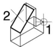

Modifying a curved face of a solid.
Top Left: Identify the solid (1), then the curved face to modify (2). Use the screen pointer to define the direction of the modification and accept (3). Top Right: The solid after modification. Bottom: Front views, showing the solid before (left) and after (right) the curved surface was modified.
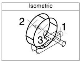
text_image
Isometric 2 1 3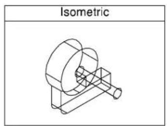
text_image
Isometric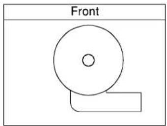
natural_image
Simple line drawing of a circular object with a rectangular base, labeled 'Front' above (no other text or symbols)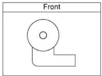
natural_image
Simple line drawing of a 3D mechanical part labeled 'Front' (no other text or symbols)Key-in: STRETCH FACES
Remove Faces and Heal

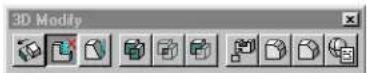
(3D only) Used to remove an existing face(s) or a feature from a solid and then heal (close) the opening. Additionally, the Logical Faces option lets you remove all faces associated with a feature by identifying any one of the feature's surfaces.
For example, with Method set to Logical Faces, identifying any one face of the feature lets you remove all faces that are associated with:
- a cut
• a solid that has been added to or subtracted from the original - a shell solid (returning the solid to its original form with no hollowing out)
• a fillet or chamfer
In operation, you can select one or more faces as follows:
• After selecting the solid, as you move the screen pointer over it, the face nearest the pointer highlights. A data point selects the highlighted face, which remains highlighted.
- You can select additional faces using
- To select a face that is behind another in the view, enter a data point (or
- You can use Resets also to deselect an incorrect face. Where a number of faces have been selected, consecutive Resets will deselect them in the reverse order (that is, the last face selected is the first face deselected).
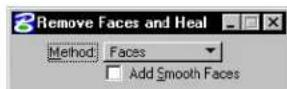
| Tool Setting | Effect |
| Method | Defines how faces are selected for removal:Logical Groups—All associated faces are processed. For example, a feature such as a cut can be removed by selecting any one face of the feature.Faces—Only selected faces are processed. |
| Add Smooth Faces | If on, any tangentially continuous faces are included with the selected face. If off, only the selected face is considered. |
To remove one or more faces from a solid
- Select the Remove Faces and Heal tool.
- From the Method option menu, choose Faces.
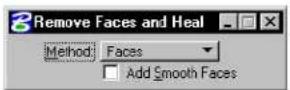
-
Identify the solid. The solid highlights. Simultaneously, the face nearest the screen pointer location highlights.
-
Identify the face to remove. The face remains highlighted.
-
Accept to remove the face. or Identify further faces to remove with
data points. -
Accept to remove the selected faces.
Removing a single face. Left: Identify the solid (1) and the face to remove (2). Right: Accept (3) to remove the selected face.
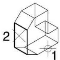
text_image
2 1
natural_image
Geometric line drawing of a 3D geometric shape with no text or symbols8-124 MicroStation User Guide
Removing multiple faces. Left: Identify the solid (1)nd the faces to remove (2 and 3). Right: Accept (4) to remove the selected faces.
text_image
2 3 1
natural_image
Isometric line drawing of a 3D geometric shape resembling a prism with an L-shaped cutout (no text or symbols)To remove a cut feature from a solid
- Select the Remove Faces and Heal tool.
- From the Method option menu, choose Logical Faces.
- Identify the solid.
The solid highlights. Simultaneously, the face nearest the screen pointer location highlights in the active color and line style.
- Identify one of the faces of the cut.
The face highlights.
- Accept to remove all faces associated with the cut.
Removing a cut feature from a solid.
Left: Identify the solid (1). Center: one of the faces of the cut
(2). Right: Accept to remove all faces associated with the cut (3).
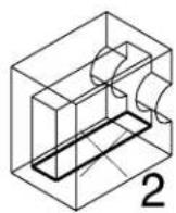
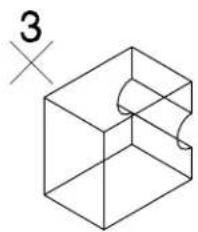
natural_image
Isometric line drawing of a 3D cube with a curved cutout and a small 'X' symbol on the left (no text or labels)Key-in: REMOVE FACES
Taper Solid

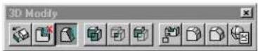
Used to taper one or more faces on a solid.
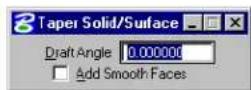
In operation, you can select one or more faces as follows:
• After selecting the solid, as you move the screen pointer over it, the face nearest the pointer highlights. A data point selects the highlighted face, which remains highlighted.
- You can select additional faces using
• To select a face that is behind another in the view, enter a data point (or
- You can use Resets also to deselect an incorrect face. Where a number of faces have been selected, consecutive Resets will deselect them in the reverse order (that is, the last face selected is the first face deselected).
| Tool Setting | Effect |
| Draft Angle | Sets the angle to be applied to the taper. |
| Add Smooth Faces | If on, any tangentially continuous faces are included with the selected face. If off, only the selected portion of the tangentially continuous face is tapered. |
To taper one or more faces on a solid
- Select the Taper Solid tool.
- In the Draft Angle field, enter the required angle for the taper.
- Identify the solid.
The solid highlights
- Identify the face to taper.
The selected face is highlighted.
-
(Optional) — Select further faces to taper using
data points. -
Accept the selected face(s).
-
Define (with a data point) the vector start point for the taper.
-
Define (with a data point) the vector end point for the taper.
The vector start and end points define the direction of the taper, on to which the Draft Angle is applied. On defining the vector end point, the taper is constructed.
Selecting a face with Add Smooth Faces off, left. The result, right.
Selecting a face with Add Smooth Faces on, left. The result, right.
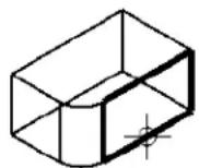
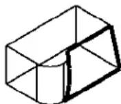
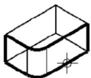
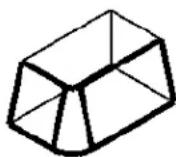
Key-in: CONSTRUCT TAPER
Construct Union

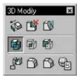
(3D only) Used to unite two or more overlapping solids.
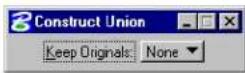
| Tool Setting | Effect |
| Keep Originals | Determines whether or not the original solids are retained after constructing the solid.None—None of the original solids are retained.All—All of the original solids are retained.First—The first solid identified is retained.Last—The last solid identified is retained. |
To construct a union between overlapping solids
- Use the Element Selection tool to select the solids.
- Select the Construct Union tool.
The solids are united into a single solid.
Alternative method — To construct a union between overlapping solids
- Select the Construct Union tool.
- Identify the first solid.
- Identify the second solid.
- Accept to construct the union.
or
Identify further solids.
- Accept to construct the union.
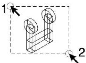
natural_image
Isometric line drawing of a 3D mechanical part with two circular features, enclosed in a dashed rectangular frame (no text or symbols)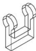
Using the Element Selection tool to unite several elements into a single solid. Left: Use the Element Selection tool to select the elements to be united (1 and 2). Right: Select the Construct Union tool to unite the selected elements.
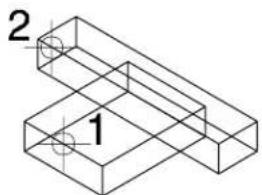
natural_image
Isometric line drawing of two stacked rectangular blocks labeled 1 and 2, with no text or symbols beyond labels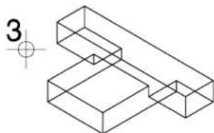
natural_image
Isometric line drawing of two connected 3D rectangular blocks with a small circle and crosshair marker (no text or symbols)Selecting elements individually to unite into a single solid. Left: After selecting the Construct Union tool, select the elements to unite (1 and 2). Right: Accept (3) to complete the construction.
Key-in: CONSTRUCT UNION
Construct Intersection

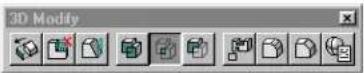
(3D only) Used to construct a solid that is the intersection of two or more overlapping solids.
Typically, you can use this tool to create a solid from the projected front and side elevations of an object.
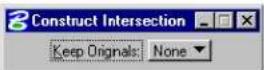
| Tool Setting | Effect |
| Keep Originals | Determines whether or not the original solids are retained after constructing the solid.None—None of the original solids are retained.All—All of the original solids are retained.First—The first solid identified is retained.Last—The last solid identified is retained. |
To construct a solid at the intersection of overlapping solids
- Use the Element Selection tool to select the solids.
- Select the Construct Intersection tool.
Alternative method — To construct a solid at the intersection of overlapping solids
-
Select the Construct Intersection tool.
-
Identify the first solid.
-
Identify the second solid.
-
Accept to construct the intersection. or
Identify further solids.
- Accept to construct the intersection.
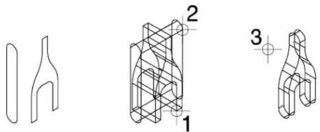
natural_image
Three technical line drawings of mechanical components with no visible text or symbolsCreating a solid from the front and side elevations of an object. Left: Front and side elevations of the required object. Center: After projecting the front and side "through" each other, select the Construct Intersection tool and identify each of the solids (1 and 2). Right: Accept (3) to create the solid at the intersection of the two original elements.
Rendered view showing the two projected elements formed from the intersection of the two projections.
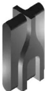
natural_image
3D rendered mechanical part with symmetrical cutouts and a central slot (no text or symbols)Rendered view showing the completed item formed from the intersection of the two projections.
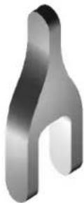
Key-in: CONSTRUCT INTERSECTION
Construct Difference

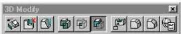
(3D only) Used to subtract the volume of one or more overlapping solids from another solid.
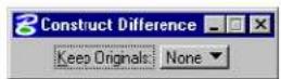
| Tool Setting | Effect |
| Keep Originals | Determines whether or not the original solids are retained after constructing the solid.None—None of the original solids are retained.All—All of the original solids are retained.First—The first solid identified is retained.Last—The last solid identified is retained. |
To construct a solid that is the difference between one solid and one or more overlapping solids
- Select the Construct Difference tool.
- Identify the solid from which the other solid(s) will be subtracted.
-
Identify the solid to subtract.
-
Accept to subtract the second solid from the first.
or
Identify further solids to subtract.
- Accept to subtract the latter solids from the First.
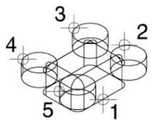
text_image
1 2 3 4 5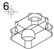
natural_image
Technical line drawing of a mechanical part with cylindrical and rectangular features (no text or symbols)Example of subtracting several solids from another. Left: Identify the solid from which the others will be subtracted (1), and then the solids to subtract from the first (2,3,4,5). Accept (6) to complete the subtraction.
Key-in: CONSTRUCT DIFFERENCE
Cut Solid

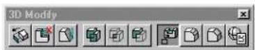
(3D only) Used to place a cut in a solid, using a cutting profile, which may be an open or a closed element. Open elements must extend to the edge of the solid. When an open element is the cutting profile, the identification point for the solid determines the portion of it that is retained. If Split Solid is on then no material is removed; the solid is split by the cut.
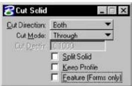
text_image
Cut Solid Cut Direction: Both Cut Mode: Through Cut Depth: 1000 Split Solid Keep Profile Feature (Forms only)| Tool Setting | Effect |
| Cut Direction | Sets the direction of the cut, relative to the cutting profile plane's Surface Normal.Both—Both (perpendicular) directions from the cutting profile's plane.Forward—In the direction of the cutting profile plane's Surface Normal.Back —In the reverse direction of the cutting profile plane's Surface Normal. |
| Cut Mode | Sets the limits of the cut.Through—Cuts through all faces of the solid.Define Depth—Cuts into the solid a defined distance. |
| Cut Depth | (Cut Mode set to Define Depth only) Sets the cut's projection distance. |
| Split Solid | If on, no material is removed from the solid; it is split into two or more segments. |
| Keep Profile | If on, the original cutting profile remains in the design. |
To create a cut in a solid using an element as the profile
- Select the Cut Solid tool.
- (Optional) — To retain the cut portion, turn on Split Solid.
- Identify the solid to cut.
- Identify the cutting element.
An arrow(s) indicates the direction of the cut. - Accept to complete the cut.
Using a closed planar element as a cutting profile to create a cut in a solid.
Top Left: Identify the solid (1) and the cutting profile (2). Top Right: Accept (3) to create the cut.
Front views show the solid nd cutting profile (left) and the completed cut (right).
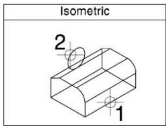
text_image
Isometric 2 1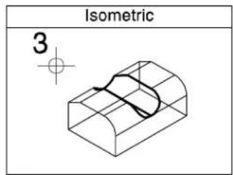
text_image
Isometric 3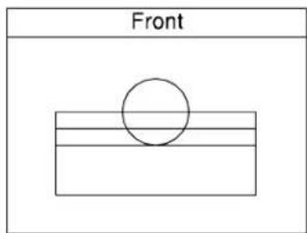
text_image
Front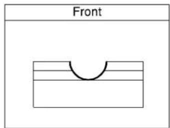
text_image
FrontWhere open elements are used as cutting profiles, the must extend at least to the edge of the solid as shown here in the front view (bottom left). Additionally, the identification point for the solid (1) determines which part of the solid is retained.
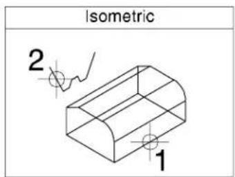
text_image
Isometric 2 1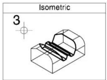
text_image
Isometric 3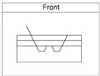
text_image
Front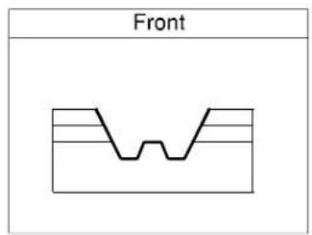
text_image
FrontWhen Split Solid is on, the solid is split into segments by the cutting profile.
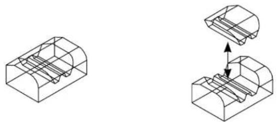
natural_image
Technical line drawing showing two 3D mechanical components with internal channels and a magnified inset view of the internal structure (no text or symbols)Key-in: CONSTRUCT CUT
Fillet Edges

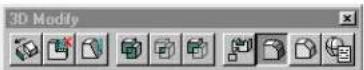
(3D only) Used to fillet, or round, one or more edges of a solid, projected surface, or a surface of revolution. To use this tool:
- Select the edge you want to fillet.
- To select additional edges, press
and, as you move the pointer over the solid or surface, the edge nearest the pointer highlights. While holding down , enter a data point to select the additional edge. - You can enter a Reset to deselect an incorrect edge. Where a number of edges have been selected, consecutive Resets will deselect them in the reverse order (that is, the last edge selected is the first edge deselected).
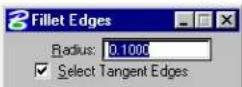
| Tool Setting | Effect |
| Radius | Defines the radius of the fillet |
| Select Tangent Edges | If on, edges that are tangentially continuous are selected and rounded in one operation. If off, only the selected section is filleted. |
To fillet one or more edges of a solid or projected surface
- Select the Fillet Edges tool.
- In the Radius field, enter the required radius.
- If required, turn on Select Tangent Edges.
- Identify an edge to fillet.
The solid highlights, with the selected edge highlighted.
- Accept to fillet the edge.
or
Identify further edges to be filleted using
- Accept to fillet the edges.
Applying fillets to edges of a solid (Top) and a ojected surface (Bottom)
Left: Identify the edges (1 and 2), which highlight.
Accept (3) to fillet the selected edges.
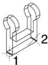
natural_image
Isometric line drawing of a mechanical bracket or bracket (no text or symbols)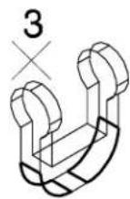
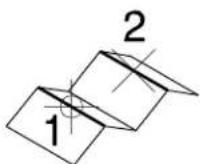
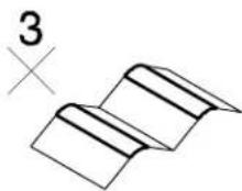
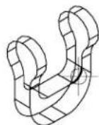
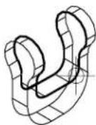
Effect of "Select Tangent Edges" setting. Left: Off — only the identified section of the edge is selected for filleting. Right: On — the identified section plus all edges that are tangentially continuous are selected for filleting.
Key-in: FILLET EDGES
Chamfer Edges

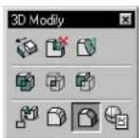
(3D only) Used to chamfer one or more edges of a solid, projected surface, or a surface of revolution. To use this tool:
- Select the edge you want to chamfer.
- To select additional edges, press
and, as you move the pointer over the solid or surface, the edge nearest the pointer highlights. While holding down , enter a data point to select the additional edge. - You can enter a Reset to deselect an incorrect edge. Where a number of edges have been selected, consecutive Resets
will deselect them in the reverse order (that is, the last edge selected is the first edge deselected).
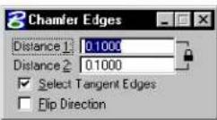
| Tool Setting | Effect |
| Distance 1/Dis- tance 2 | Sets the distances to trim back the faces. If the Lock control is on, they are constrained to the same value. |
| Lock control | ·If on (closed) Distance 1 and Distance 2 are the same value. ·If off (open) Distance 1 and Distance 2 can be different. |
| Select Tangent Edges | If on, edges that are tangentially continuous are selected and chamfered in one operation. If off, only the selected section is chamfered. |
| Flip Di-rection | Where Distance 1 and Distance 2 are different, reverses the direction of the chamfer and the values that the faces are trimmed. |
To chamfer one or more edges of a solid
- Select the Chamfer Edges tool.
- In the Distance 1 and Distance 2 fields, enter the required values.
- If required, turn on Select Tangent Edges.
- Identify an edge to chamfer.
The solid highlights, with the selected edge highlighted.
- Accept to chamfer the edge.
or
Identify further edges to be chamfered using
- Accept to chamfer the edges.
Applying a chamfer to an edge of a solid (Top) and a projected surface (Bottom).
Left: Identify the edge (1), which highlights.
Right: Accept to chamfer the selected edge (2).
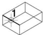
2
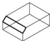
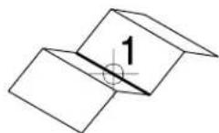
2
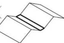
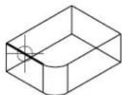
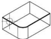
Effect of "Select Tangent Edges" setting. Left: Off — only the identified section of the edge is selected for chamfering. Right: On — the identified section plus all edges that are tangentially continuous are selected for chamfering.
To correct a chamfer that is constructed in the wrong direction (that is, Distances 1 and 2 are applied to the wrong faces)
- Undo the chamfer.
- Turn on Flip Direction.
- Reconstruct the chamfer.
Key-in: CHAMFER EDGES
Edit 3D Primitive

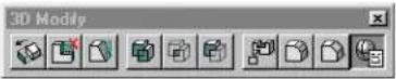
Used to modify existing 3D elements by editing their parameters.
Dimensions available for editing depend on the 3D primitive element chosen.
| 3D Primitive Editable parameters | |
| Slab Length, Width, and Height. | |
| Sphere Radius | |
| Cylinder/Cone | Top Radius, Base Radius, and Height. |
| Torus | Primary Radius, Secondary Radius, and Angle. |
| Wedge | Radius, Angle, and Height |
| Extrusion | Distance |
| Revolution | Angle (of revolution) |
To edit a 3D primitive element
-
Select the Edit 3D Primitive tool.
-
Identify the 3D primitive.
The element highlights.
- Accept the element.
A dialog box opens with the editable dimensions displayed, showing the existing values.
-
Make changes, as required, to the dimension(s).
-
Click OK.
The 3D primitive is modified to match the new values.

If you extrude a block, it is recognized as a slab by the Edit 3D Primitive tool, thus letting you edit the Length, Width, and Height (not just the extruded distance).
Key-in: EDIT PRIMITIVE
3D Utility tool box
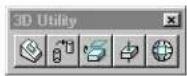
Tools in the 3D Utility tool box are used to:
- Relocate elements so their faces are aligned.
- Change the display of SmartSolids.
- Extract a face or edge from a solid or surface.
• Intersect a solid or surface with a linear element.
- Construct a faceted element from an existing solid or surface.
| To | Select in the 3D Utility tool box |
| Move an element and align a selected face of it to the selected face of a second element. |  Align Faces (see page 8-146) Align Faces (see page 8-146) |
| Change the display of SmartSolids/SmartSurfaces |  Change SmartSdid Display (see page 8-151) Change SmartSdid Display (see page 8-151) |
| Extract a face, or edge, from a solid or surface. |  Ex tr act Face or Edge Ge o met ry (see page 8-154) Ex tr act Face or Edge Ge o met ry (see page 8-154) |
| Find the intersection point between a solid/surface and a linear element. |  Intersect Solid/Surface with Curve (see page 8-157) Intersect Solid/Surface with Curve (see page 8-157) |
| Construct a faceted element from a solid or surface. |  Construct Fact (see page 8-159) Construct Fact (see page 8-159) |
Key-in: DIALOG TOOLBOX 3DQUERY [OFF | ON | TOGGLE]
Align Faces

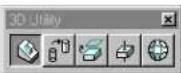
Used to relocate an element to align a selected face of the first element to a selected face of a second element.
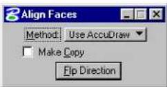
| Tool Setting | Effect |
| Method | Sets the way that the planes of the faces are selected.Use AccuDraw—AccuDraw's drawing plane is used to define the orientation of the faces.By 3 Points—The orientation of the planes are defined by 3 points. |
| Use ACS for | (Method set to By 3 Points only) Sets the way that the orientation of the selected face's plane is calculated.Neither—Orientation for both faces is defined by 3 points.Element—Orientation for the first element is taken from the ACS. If no ACS is active, the design file coordinate system is used.Placement—Orientation for the placement of the first element is taken from the ACS. If no ACS is active, the design file coordinate system is used. |
| Make Copy | If on, a copy of the first element is used and the original element is not manipulated. |
| Flip Direction | Lets you reverse the direction of the aligned element. |
To align the faces of two elements using AccuDraw
- Select the Align Faces tool.
- Set Method to Use AccuDraw.
- Identify the element to align.
The element highlights.
- Move the pointer over the element to highlight the required face and accept.
- Identify the second element.
- Move the pointer over the element to highlight the required face and accept.
The first element is relocated with the selected faces aligned. The first element is positioned symmetrically on the face of these second element.
Aligning faces of two elements using AccuDraw.
Identify the first element (1) and the face to be aligned (2), the second element (3), and the face to align with 40.
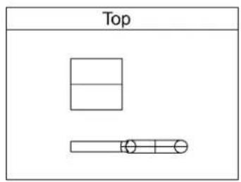
text_image
Top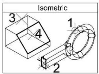
text_image
Isometric 1 2 3 4
text_image
Front
text_image
RightAfter the two elements are aligned at the seleade faces.
text_image
Top
text_image
Isometric
text_image
Front
flowchart
graph TD
    A["Right"] --> B(( ))
To align the faces of two elements without using AccuDraw
- Select the Align Faces tool.
- Set Method to By 3 Points.
- Set Use ACS for to Neither.
- Identify the element to align.
The element highlights.
- Accept the element.
- Define the "from" coordinate origin. This defines the origin point for the element that is being aligned.
- Define the "from" coordinate first axis point.
A red arrow appears, showing the direction of the first (x) axis.
- Define the "from" coordinate second axis point.
Green and blue arrows appear, showing the direction of the second
(y) axis and the third (z) axis' directions, respectively.
-
Define the "to" coordinate origin. This defines the origin point for the relocation. The first element's origin point will be located at this point.
-
Define the "to" coordinate first axis point.
A red arrow appears, showing the direction of the first (x) axis.
- Define the "to" coordinate second axis point.
Green and blue arrows appear, showing the direction of the second (y) axis and the third (z) axis' directions, respectively.
Simultaneously, the first element is relocated with its defined axes aligning exactly with those of the second element.
Aligning faes of two elements.
Identify and accept the first element (1,2).
Define the "from" coordinate origin (3), first axis point (4) and second axis point (5).
Define the "to" coordinate origin (6), first axis point (7) and second axis point (8).

flowchart
graph TD
    A["3D Shape with labeled parts"] --> B["1,2 Component"]
    B --> C["2D View with labeled points 3,4,5,6,7,8"]
    C --> D["3D View with point 6"]
After the two elements are aligned relative to h defined coordinate systems.
text_image
Top
text_image
Isometric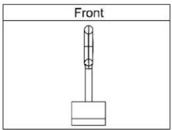
natural_image
Simple line drawing of a vertical rod mounted on a base, labeled 'Front' (no other text or symbols)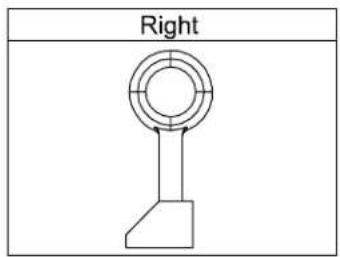
text_image
RightKey-in: ALIGNFACE
Change SmartSolid Display

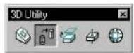
(3D only) Used to:
- Change the number of Iso Lines used to display SmartSolids and SmartSurfaces.
- Change the display from Wireframe mode to Surface
mode and vice-versa.
• Suppress rule lines for B-spline and/or complex blending faces.
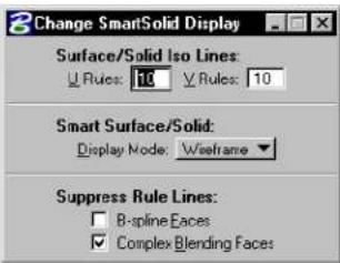
text_image
Change SmartSolid Display Surface/Solid Iso Lines: Rules: 10 Rules: 10 Smart Surface/Solid: Display Mode: Weisframe Suppress Rule Lines: B-spline Faces Complex Blending Faces| Tool Setting | Effect |
| Surface/Solid Iso Lines | Sets the number of rule lines that represent a full 360° of curvature of curved surfaces for SmartSolids and SmartSurfaces.U Rules—Sets the number of lines in the U direction.V Rules—Sets the number of lines in the V direction. |
| Smart Surface/Solid | Lets you set the Display Mode for SmartSurfaces and SmartSolids.Display mode—Sets the display mode for SmartSurfaces and SmartSolids:Surfaces — Required only if the design is to be rendered with earlier versions of MicroStation.Wireframe — The default display mode, which should be used unless the design is to be rendered with an earlier version of MicroStation. |
| Suppress Rule Lines | Lets you suppress, or turn off, the display of rule lines for particular faces on SmartSolids and SmartSurfaces.B-spline faces—If on, display of rule lines on B-spline faces can be suppressed.Complex Blending Faces—If on, display of rule lines on complex blending faces can be suppressed. |
To change the SmartSolid display settings of an element
- Select the Change SmartSolid Display tool.
- Make changes to the settings, as required.
- Identify the solid.
- Accept.
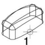
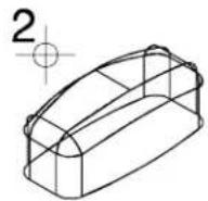
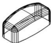
Changing the SmartSolid display from Wireframe Mode to Surface Mode (with Surface/Solid Iso Lines set at 5). Left: Identify the solid (1). Center: Accept to effect the change (2). Right: The same solid displayed in surface mode with Surface Rule Lines increased from 5 to 10.
Key-in: CHANGE BREP DISPLAY
Extract Face or Edge Geometry

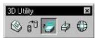
(3D only) Used to extract a face or edge from a solid or surface. Tool settings let you define the symbology (level, color, weight, and style) of the extracted face or edge.
In operation, you can select one or more faces on a solid or surface, as follows:
• After selecting the solid or surface, as you move the screen pointer over it, the face nearest the pointer highlights. A data point selects the highlighted face, which remains highlighted.
- You can select additional faces using
- To select a face that is behind another in the view, enter a data point (or
- You can use Resets also to deselect an incorrect face. Where a number of faces have been selected, consecutive Resets will deselect them in the reverse order (that is, the last face selected is the first face deselected).
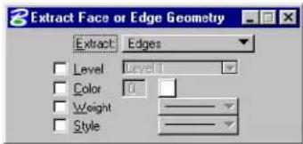
text_image
Extract Face or Edge Geometry Extract Edges Level Level Color 0 Weight Style| Tool Setting | Effect |
| Extract | S e t s t h e t y p e o f e l e m e n t t o b e e x t r a c tFaces—Extract selected faces from the solid or surface.Edges—Extract selected edges from the solid or surface.Untrimmed Surfaces—Extract the untrimmed surface. That is, the original surface, prior to modification. |
| Level If on, sets the level on which the extracted element is placed. | |
| Color | If on, sets the color of the extracted element. |
| Weight | If on, sets the line weight of the extracted element. |
| Style | If on, sets the line style of the extracted element. |
To extract a face from a solid or surface
- Select the Extract Face or Edge Geometry tool.
- If required, turn on and set symbology settings.
- Identify the solid or surface.
- Identify one or more faces on the solid or surface (after selecting the first face with a data point, additional faces can be selected with
data points). - Accept.
Identify the solid (1), select the face (2), accept the fac(3).
With Extract set to Faces (top), and Untrimmed Surfaces (bottom).
Key-in: EXTRACT FACE
Intersect Solid/Surface with Curve

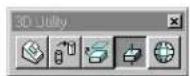
(3D only). Used to find the intersection point between a solid/surface and a linear element (curve).
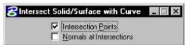
| Tool Setting | Effect |
| Intersection Points | If on, locates the intersection point of the curve with the solid/surface. |
| Normals at Inter-sections | If on, displays the surface normal at the point of intersection of the curve with the solid/surface. |
To construct points and surface normals at the intersection of a line with a solid
- Select the Intersect Solid/Surface with Curve tool.
- Turn on Intersection Points and Normals at Intersections.
- Identify the solid.
- Identify the line.
- Accept.
Constructing points and surface normals at the intersection of a line with a solid.
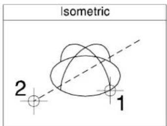
text_image
Isometric 2 1Above: Identify the solid (1) and the line (2).
Below: Accept to construct the points and surface normals.
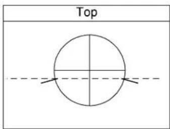
text_image
Top
text_image
Isometric 3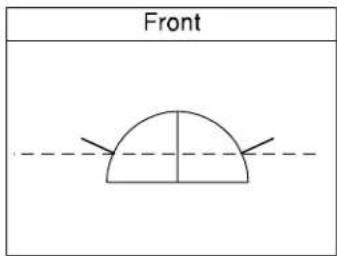
text_image
Front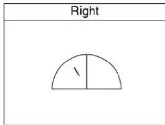
text_image
Right /Key-in: INTERSECT CURVE SURFACE
Construct Facet

Used to create a set of planar shapes from a 3D element, based on a defined tolerance. The shapes can be saved in a single element called a mesh element, or they can be saved to the design file as individual elements.
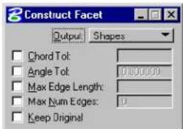
text_image
3 Construct Facet Output Shapes Chord Tol: Angle Tol: 0.00000 Max Edge Length: Max Num Edges: 0 Keep Original| Tool Setting | Effect |
| Output | Lets you select the type of element to be constructed: Shapes—The constructed element is placed in the design as polygons in a graphic group.Mesh Element—The constructed element is placed in the design as a single mesh element. |
| Chord Tol | If on, lets you define the maximum deviation from a constructed polygon to the original element. |
| Angle Tol | If on, lets you define the maximum angle allowed between the normal directions of two adjacent polygons in the constructed element. |
| Max Edge Length | If on, lets you define the maximum edge length for any polygon in the constructed element. |
| Max Num Edges | If on, lets you define the maximum number of edges for any polygon in the constructed element. |
| Keep Original | If on, the original element is retained. |
To construct a faceted element
- Select the Construct Facet tool.
- In the tool settings window, adjust settings as required.
- Identify the surface or solid.
- Accept the surface or solid.
Identify the element (1) and accept (2) to construct the faceted element.
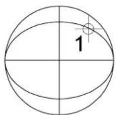
text_image
1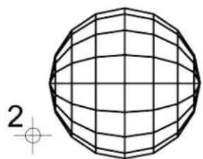
natural_image
Geometric wireframe sphere with grid lines, no text or symbols presentRendered image showing original element left and the faceted element right.
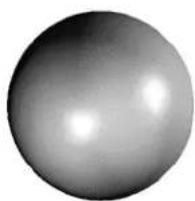
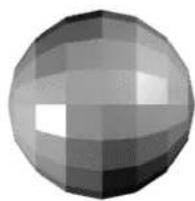
Key-in: CONSTRUCT FACET
Surface Modeling tool frame
The Surface Modeling tool frame provides access to all of the "child" 3D surface modeling tool boxes.
| To | Use tools in the |
| Place or construct a free-form B-spline surface. orConstruct a skin surface; or a surface by section, network, edges, or off orConstruct a surface by sweeping an element along two traces or along a helical curve. |  Create Surfaces tool box (see page 8-162)set . Create Surfaces tool box (see page 8-162)set . |
| Trim, extend, stitch, split, or punch surfaces. orChange B-spline specific element attributes. orRemove a trim boundary from a surface. |  Modify Surfaces tool box (see page 8-182) Modify Surfaces tool box (see page 8-182) |
| Construct a fillet or blend between surfaces. |  Fillet Surfaces tool box (see page 8-202) Fillet Surfaces tool box (see page 8-202) |
| Evaluate surfaces. |  3D Queries tool box (see page 8-210) 3D Queries tool box (see page 8-210) |
Key-in: DIALOG TOOLBOX SURFACE [OFF | ON | TOGGLE]
Create Surfaces tool box
The tools in the Create Surfaces tool box are used to place or construct a free-form, helical, or offset surface, and to construct a surface by cross-sections, edges, skin, or by sweeping along two traces.
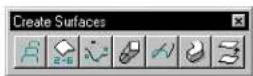
| To | Select in Create Surfaces tool box |
| Construct a B-spline surface that is transformed between section elements, or elements of a network. |  Construct Surface by Section or Network (see page 8-163) Construct Surface by Section or Network (see page 8-163) |
| Construct a B-spline surface that contains selected elements as edges. |  Construct Surface by Edges (see page 8-166) Construct Surface by Edges (see page 8-166) |
| Place or construct a free-form B-spline surface. |  Place Free-form Surface (see page 8-169) Place Free-form Surface (see page 8-169) |
| Construct a B-spline surface by transforming one element (section) to a second element (section) as it is projected along a linear element (the trace). |  Construct Skin Solid/Surface (see page 8-174) Construct Skin Solid/Surface (see page 8-174) |
| Create a B-spline surface by sweeping one or two section profile curves along two trace curves. |  Sweep Along Two Traces (see page 8-175) Sweep Along Two Traces (see page 8-175) |
| Create a helical-shaped B-spline surface by sweeping a section profile curve along a pre-defined helix curve. |  Construct Helical Surface (see page 8-179) Construct Helical Surface (see page 8-179) |
| Construct a B-spline surface that is offset from another surface. |  Offset Surface (see page 8-181) Offset Surface (see page 8-181) |
Key-in: DIALOG TOOLBOX 3DFREEFORM [OFF | ON | TOGGLE]
Construct Surface by Section or Network

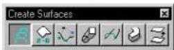
(3D only) Used to construct a B-spline surface that is transformed between section elements, or elements of a network.
All section elements must be in the same direction to avoid the
resulting surface from being "twisted". Before using Construct Surface by Section or Network, use the Change Element Direction (see page 7-116) tool in the Modify Curves tool box to change the sections' directions and start points so they are in a similar position to each other. As a final check, visual aids display each element's direction as it is selected.
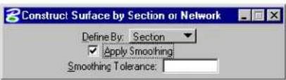
text_image
Construct Surface by Section or Network Define By: Section ✓ Apply Smoothing Smoothing Tolerance:| Tool Setting | Effect |
| Define By | Sets how the surface is constructed.Section—Transformed between sections (lines, line strings, arcs, ellipses, complex chains, complex shapes, or B-spline curves). The order in the u-direction is 4. The order in the v-direction is determined by the sections.Network—A Gordon surface is constructed, interpolating a network of elements. Each element in the network's u-direction must intersect all elements in its v-direction, and vice-versa. |
| Apply Smoothing | (Define By set to Section only)If off, the continuities of the constructed surface are those of the input cross-sections.If on, each input cross-section is approximated by a smooth B-spline curve within the specified Tolerance value, and the surface is created from the approximation curves. |
| Smoothing Tolerance | (Apply Smoothing on only) Lets you change the value of the smoothing tolerance value. Smaller tolerance values cause the constructed surface to follow the construction elements more closely. |
To construct a B-spline surface by cross-sections
- Select the Construct Surface by Section or Network tool.
- In the Tool Settings window, set Define By to Section.
- Identify the sections in the order that the transformation is to follow. (You can Reset to reject a section.)
- Accept to display the B-spline surface.
- Accept the B-spline surface.
Top Left: Identify the section lements (1,2,3, and 4). Arrows display to verify the element direction. Top Right: Accept to display the B-spline surface (5) and accept again to create the surface (6).
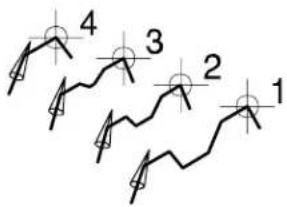
text_image
4 3 2 1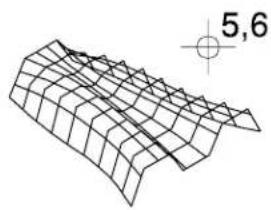
natural_image
3D wireframe surface plot with grid lines and coordinate axis indicator (no text labels or annotations)With Apply Smoothing turned on, each section element is approximated by a B-spline curve, with the resulting surface being smoother.
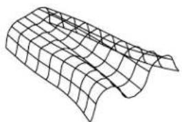
natural_image
3D wireframe model of a curved surface with grid lines (no text or symbols)To construct a surface that interpolates a network of elements
- Select the Construct Surface by Section or Network tool.
- In the Tool Settings window, set Define By to Network.
- Identify the first curve in the u-direction.
- In order, identify the other curves in the u-direction.
- Accept the curves in the u-direction.
- Identify the first curve in the v-direction.
- In order, identify the other curves in the v-direction.
- Accept the curves in the v-direction.
- Accept the B-spline surface.
Key-in: CONSTRUCT SURFACE CROSSSECTION

Each element (curve) in the u-direction must intersect each element (curve) in the v-direction of the network.
Construct Surface by Edges

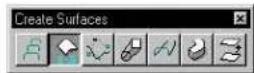
(3D only) Used to construct a B-spline surface that has elements (lines, line strings, shapes, arcs, curves, B-spline curves, complex chains, and complex shapes) as edges. Where the number of edges is three to six inclusive, they must meet at their endpoints.
- If there are two edges, a ruled surface, connecting either the closest or the farthest ends, is constructed between the boundaries.
- If there are three edges, the tool settings let you choose between a Coons patch, or an n-sided patch.
- If there are four edges, a bi-cubically blended Coons patch is created.
- If there are five or six edges, then three five or six surfaces, respectively, are joined to form one patch.
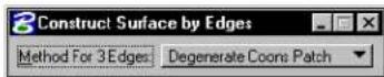
| Tool Setting | Effect |
| Method For 3 Edges | Lets you choose how the surface is constructed from 3 edges: Degenerate Coons Patch N-sided Patch |
To construct a surface by edges
- Use the Element Selection tool to select the edges.
- Select the Construct Surface by Edges tool.
- Accept the surface.
Alternative method — To construct a surface by edges
- Select the Construct Surface by Edges tool.
- Identify the first edge.
- Identify the other edge(s).
- Enter a data point to display the surface.
- Accept the surface.
Left: Select the edges (1–4). Accept to view the face (5). Accept again to construct the surface (6). Right: The completed surface.
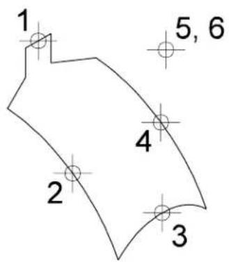
text_image
1 5, 6 4 2 3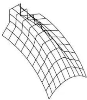
natural_image
3D wireframe surface plot showing grid structure (no text or symbols)Key-in: CONSTRUCT SURFACE EDGE

If there are two edges, Resetting during the final step causes an alternative surface to be displayed. This surface then can be accepted or rejected.
Place Free-form Surface

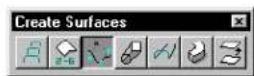
(3D only) Used to place or construct a free-form B-spline surface.
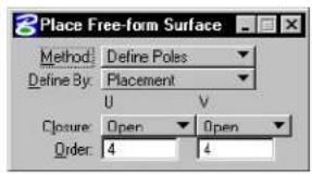
text_image
Place Free-form Surface Method: Define Poles Define By: Placement U V Closure: Open Open Order: 4 4| Tool Setting | Effect |
| Method | Sets how the surface is generated.Define Poles—Poles (vertices) of the control net are defined by data points or vertices of elements. The number of poles in the u- and v-direction must be greater than or equal to the order in that direction.Through Points—Surface passes through the points defined by the data points or vertices of elements and is interpolated at each point. One pole is defined for each data point, the number of which must be greater than or equal to the Order.L-Square By Tol—The surface is approximated based on the points defined by the data points or the vertices of the identified line string or shape. The maximum deviation of the input points from the surface is adjustable using the Tolerance setting. After the approximation surface is created, the maximum deviation and the mean deviation are displayed in the status field.L-Square By Num—The sum of the squares of the distances from the data points or vertices of elements to corresponding points on the surface is minimized. The control net has the active number of Poles in the u- and v-direction. If the maximum error exceeds the Tolerance, the maximum error is displayed in the status bar. ^1 Catmull-Rom—Fourth-order NURBS surface that is interpolated to closely resemble the overall shape defined by the data points entered or vertices of the selected line strings. |
| Define By | Sets how the surface is created.Placement—The surface is placed by entering data points.Construction—The surface is constructed based on the vertices of line strings or shapes. |
| Closure | Sets whether surface is Open or Closed in the u- or v-direction. |
| Order | The order of the equation that defines the surface in the u- or v-direction (2-15). |
| Poles | The number of poles in the u- or v-direction, if Method is L-Square By Num (2–101). |
| To le r -ance | Sets the fitting or approximation tolerance, when Method is set to L - Square By T ol. The m i n distance from any one of the input data points to the surface is less than this value. The minimum distance is computed by projecting a point to the surface. |
1 The Tolerance is set in the B-splines and 3D dialog box (Element > B-spline and 3D).
To place a free-form surface with data points
- Select Place Free-form Surface tool.
- Set Define By to Placement.
- Enter a series of data points to define the first row (in the u-direction).
| Method | Each data point defines |
| Define Poles | One of the control net's poles. |
| Through Points | A point through which the surface must pass. |
| L-Square By Tol or L-Square By Num | One of a set of points that is approximated. |
- Reset to complete the first row.
The number of data points in the first row must be greater than or equal to the Order in the u-direction.
- Enter more data points to define other rows. After the same number of data points as in the first row is entered, the row
is completed and a new row is started.
- Reset to complete the definition.
If at least as many rows as the Order in the v-direction are completely defined, a B-spline surface is generated.
Placing a free-form surface by during data points (Method set to Define Poles). A Reset was entered after data points 4 and 12.
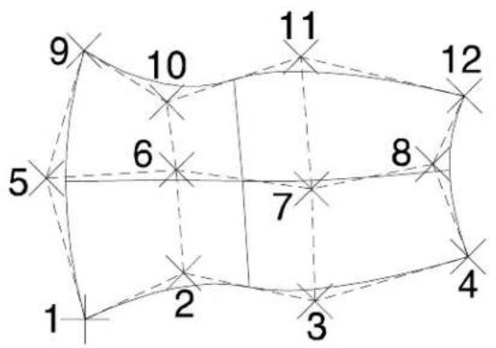
flowchart
graph TD
    1 --> 2
    2 --> 3
    3 --> 4
    4 --> 5
    5 --> 6
    6 --> 7
    7 --> 8
    8 --> 9
    9 --> 10
    10 --> 11
    11 --> 12
    12 --> 13
    13 --> 14
    14 --> 15
    15 --> 16
    16 --> 17
    17 --> 18
    18 --> 19
    19 --> 20
    20 --> 21
    21 --> 22
    22 --> 23
    23 --> 24
    24 --> 25
    25 --> 26
    26 --> 27
    27 --> 28
    28 --> 29
    29 --> 30
    30 --> 31
    31 --> 32
    32 --> 33
    33 --> 34
    34 --> 35
    35 --> 36
    36 --> 37
    37 --> 38
    38 --> 39
    39 --> 40
    40 --> 41
    41 --> 42
    42 --> 43
    43 --> 44
    44 --> 45
    45 --> 46
    46 --> 47
    47 --> 48
    48 --> 49
    49 --> 50
    50 --> 51
    51 --> 52
    52 --> 53
    53 --> 54
    54 --> 55
    55 --> 56
    56 --> 57
    57 --> 58
    58 --> 59
    59 --> 60
    60 --> 61
    61 --> 62
    62 --> 63
    63 --> 64
    64 --> 65
    65 --> 66
    66 --> 67
    67 --> 68
    68 --> 69
    69 --> 70
    70 --> 71
    71 --> 72
    72 --> 73
    73 --> 74
    74 --> 75
    75 --> 76
    76 --> 77
    77 --> 78
    78 --> 79
    79 --> 80
To construct a free-form surface based on an element's vertices
- Select the Place Free-form Surface tool.
- Set Define By to Construction.
- Identify the elements in the sequence that the B-spline surface is to follow.
- Accept the B-spline surface.
Alternative method — To construct a free-form surface based on an element's vertices
- Use the Element Selection tool to select the elements in the sequence that the B-spline surface is to follow.
- Select the Place Free-form Surface tool.
- Accept the B-spline surface.
Left: Identify the elements, in the sequence that the B-spline surface is to follow (points 1 to 4). Right: Accept (5) to create the B-spline surface.
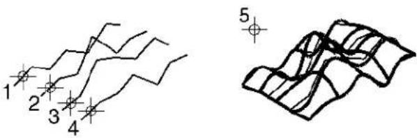
Rendered view of the B-spline surface.
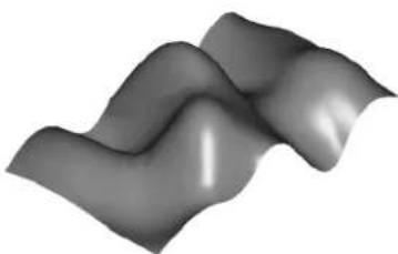
natural_image
Abstract grayscale wavy surface with smooth gradients (no text or symbols)Key-in: PLACE SURFACE
Construct Skin Solid/Surface

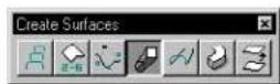
(3D only) Used to construct a B-spline surface by transforming two elements (sections) along another element (the trace). The sections and trace can be lines, line strings, arcs, ellipses, complex chains, complex shapes, or B-spline curves.
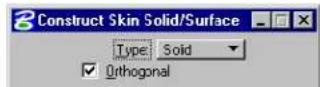
| Tool Setting | Effect |
| Type | Can be Surface (not capped) or Solid (capped). |
| Orthogonal | If on, each section is rotated to be perpendicular to the trace. |
To construct a B-spline surface by skin
- Select the Construct Skin Solid/Surface tool.
- Identify the trace.
- Identify the first section.
- Identify the second section.
- Enter a data point to display the B-spline surface.
-
Accept the surface.
-
Place the section elements in their correct position (orientation and location) on the trace element.
Left: Identify the skin path (1), and the two profiles 2, (3). Right: Accept to view the surface (4), and again to construct it (5).
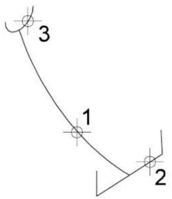
text_image
3 1 2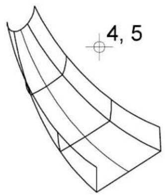
text_image
4, 5Key-in: CONSTRUCT SURFACE SWEEP
Sweep Along Two Traces

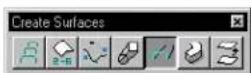
(3D only) Used to create a B-spline surface by sweeping one or two section profile curves along two trace curves.
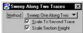
| Tool Setting | Effect |
| Method | Sets the number of section profile curves.Sweep One Along Two—one section profile curve.Sweep Two Along Two—two section profile curves. |
| Scale To Second Trace | If on, the section profile curve is scaled as it sweeps along the two trace curves. If off, the second trace curve simply serves to control orientation. This option is enabled only if Method is set to Sweep One Along Two. |
| Scale Section Height | If on, the section profile curve is also scaled in the height direction. This option is enabled only if Method is set to Sweep One Along Two and Scale To Second Trace is on. |
To sweep a section profile curve(s) along two trace curves
- Select the Sweep Along Two Traces tool.
- Identify the first trace curve.
- Identify the second trace curve.
- Identify the first (or only) section profile curve.
- If Method is set to Sweep Two Along Two, identify the second section profile curve.
- Accept.
The surface is generated and displayed.
- Accept the surface.
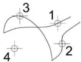
text_image
3 1 4 2Sweep One Along Two: Identify the first (1) and second (2) trace curves followed by the profile curve (3). Enter a data point (4) to view the surface. Accept/Reject the surface.
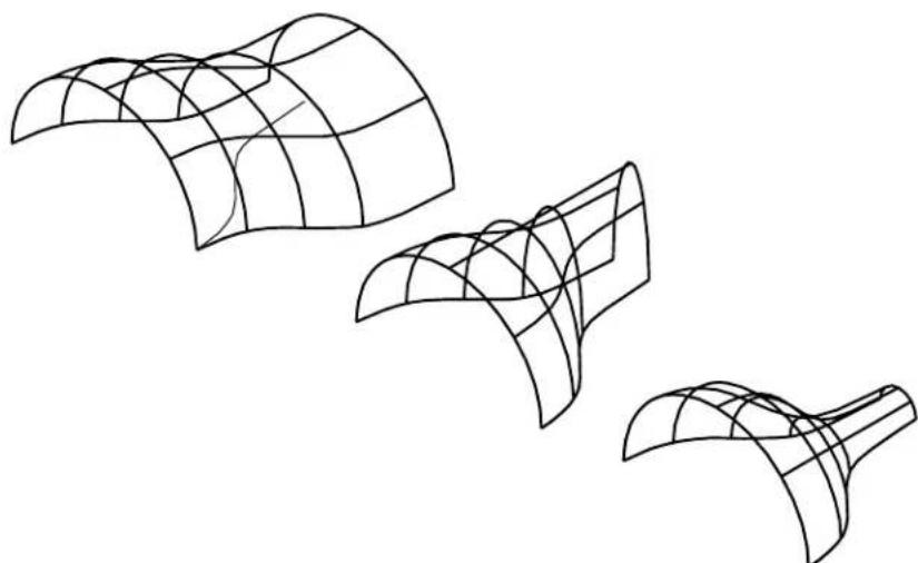
natural_image
Line drawing of three abstract curved surfaces with grid patterns, no text or symbols presentLeft: With Scale to Second Trace turned off, the profile curve is swept along the first trace. Center: With Scale to Second Trace turned on, the profile (width) is scaled to the second trace, as it is swept along the first trace. Right: With Scale Section Height turned on, both the width and the height of the profile are scaled as it is swept along the first trace.

text_image
3 1 4 2 5Sweep Two Along Two: Identify the first (1) and second (2) trace, followed by the first (3) and second (4) profile curves. Enter a data point (5) to view the surface. Accept/Reject the surface.
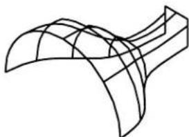
natural_image
Pure 3D wireframe diagram of a curved structural element (no text or symbols)The surface is scaled to the second trace as it is swept along the first. At the same time it transitions from the first profile to the second.
Key-in: CONSTRUCT SURFACE TRACE
Construct Helical Surface

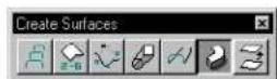
(3D only) Used to construct a helical-shaped B-spline surface by sweeping a section profile curve along a pre-defined helix curve. The section profile curve needs to be placed at one end of the helix curve. Before using this tool, you must also place a line that represents the axis direction of the helix curve; only the direction of the line matters.
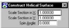
| Tool Setting | Effect |
| Scale Section in X | Sets the factor by which the section profile curve is scaled as it sweeps along the helix curve in the direction from the starting point of the helix curve to its center point — that is, the radius direction. |
| Scale Section in Y | Sets the factor by which the section profile curve is scaled as it sweeps along the helix curve in the direction of the helix axis — that is, the height direction. |
| Spin Angle | Sets the angle at which the profile is spun as it sweeps along the helix curve. |
To construct a helical-shaped B-spline surface
- Select the Construct Helical Surface tool.
- Identify the trace helix curve.
- Identify the section profile curve.
- Identify the line that represents the axis direction of the helix curve.
- Accept.
The surface is generated and displayed.
- Accept the surface.
Left: Identif the helix (1) the profile (2) and a line defining the direction of the helix (3).
Right: Accept (4) to view the helical surface.
Accept/Reject the surface.
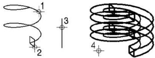
text_image
Technical diagram showing three labeled mechanical or electrical components with numbered callouts and cross-sectional views.Rendered view of the helical surface.
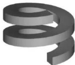
natural_image
3D rendered gray curved shape resembling a stylized number or symbol (no text or symbols present)Key-in: CONSTRUCT SURFACE HELICAL

Even though this tool is designed for helical sweeping situations, the trace curve does not have to be a helix curve. It can be
considered as a more generalized rigid sweep tool.
Offset Surface

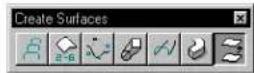
(3D only) Used to construct a B-spline surface by offsetting an extruded surface, surface of revolution or a B-spline surface.
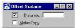
| Tool Setting | Effect |
| Distance | If on, sets the offset distance in the surface normal direction. |
| Make Copy | If on, the element is copied and the original is not manipulated. |
To construct an offset surface
- Select the Offset Surface tool.
- Identify the surface.
- Enter a data point.
If Distance is off, this data point defines the distance and direction to offset the surface.
If Distance is on, this data point defines the direction only.
Left: Identify the surface (1) then define the diction and/or distance (2). Right: The completed offset surface.
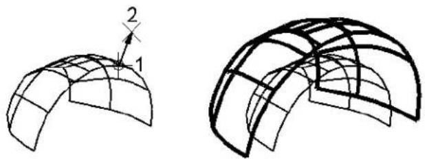
natural_image
Two 3D wireframe diagrams showing curved structural surfaces with grid patterns, one labeled with dimension '2' and the other with a number '1' (no text or symbols beyond labels)Key-in: CONSTRUCT OFFSET SURFACE
Modify Surfaces tool box
The tools in the Modify Surfaces tool box are used to create new surfaces from the union, intersection, or difference between surfaces; to trim, extend, stitch, split, punch, or extrude surfaces; or to change B-spline specific attributes.
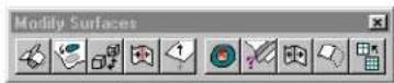
| To | Select in the Modify Surfaces tool box |
| Trim two elements to their common intersection. |  Construct Trim (see page 8-184) Construct Trim (see page 8-184) |
| Punch a hole in a surface, or to project a B-spline curve onto a surface. |  Project Trim (see page 8-187) Project Trim (see page 8-187) |
| Switch between surface types, or add caps to extrusions and surfaces of revolution. |  Convert 3D (see page 8-190) Convert 3D (see page 8-190) |
| To stitch two surfaces together to form a single surface. | [BGXA]Construct Stitch (see page 8-191) |
| Change the normal direction of a surface element. |  Change Normal Direction (see page 8-192) Change Normal Direction (see page 8-192) |
| Reverse these sense of the boun of a B-spline surface.orRemove one or all boundaries (holes) from a B-spline surface. |  Untrim Surface (see page 8-193) Untrim Surface (see page 8-193) |
| Change a surface's B-spline-specific attributes to the active B-spline settings. |  Change to Active Surface Settings (see page 8-195) Change to Active Surface Settings (see page 8-195) |
| Split, or break, an element into two separate surfaces. |  Split Surface (see page 8-197) Split Surface (see page 8-197) |
| Construct a B-spline surface extension to an element. |  Extend Surface (see page 8-198) Extend Surface (see page 8-198) |
| Rebuild a B-spline surface. | [4x2W]Rebuild Surface (see page 8-199) |
Key-in: DIALOG TOOLBOX 3DMODSURF[OFF | ON | TOGGLE]
Construct Trim

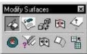
(3D only) Used to do the following:
- Trim two elements to their common intersection
- Trim one element to its intersection with a second.
- Impose boundaries onto the first selected element, or both elements, at their common intersection.
- Construct a curve along the common intersection of the two elements.
When using this tool, before accepting the trim, you can adjust the various tool settings to suit.
When selecting elements for trimming, the identified portion of the element is retained. Before accepting the trim, you can turn on Flip 1st, or Flip 2nd, for the first or second selected element respectively. These toggles reverse the portion that is retained and are useful if you inadvertently identify the wrong portion.
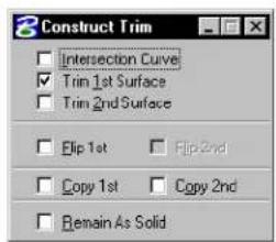
text_image
Construct Trim Intersection Curve Trim 1st Surface Trim 2nd Surface Flip 1st Flip 2nd Copy 1st Copy 2nd Remain As Solid| Tool Setting | Effect |
| Intersection Curve | If on, a curve is constructed along the common intersection of the surfaces. |
| Trim 1st Surface | If on, the first surface identified is trimmed to its intersection with the second element. |
| Trim 2nd Surface | If on, the second surface identified is trimmed to its intersection with the first element. |
| Flip 1st | Sets which portion of the 1st selected element is retained after trimming. If on, the selected portion is deleted; if off, the selected portion is retained. |
| Flip 2nd | Sets which portion of the 2nd selected element is retained after trimming. If on, the selected portion is deleted; if off, the selected portion is retained. |
| Copy 1st | If on, a copy is made of the first selected element, and the original element is retained in the design. |
| Copy 2nd | If on, a copy is made of the first selected element, and the original element is retained in the design. |
| Remain As Solid | If on, a trimmed solid remains as a solid after trimming, and a surface remains untrimmed.If off, a trimmed solid is converted to a surface and trimmed. |
To trim two elements to their common intersection
-
Select the Construct Trim tool.
-
Identify the first element.
This data point identifies the portion of the surface to be trimmed. If Flip 1st is off, then the identified portion is kept, and vice versa.
- Identify the second element.
This data point identifies the portion of the surface to be trimmed. If Flip 2nd is off, then the identified portion is kept, and vice versa.
-
Accept to view the trim.
-
Accept to trim the elements.
Trimming two elements to at their common intersection point.
Top Left: Identify the two surfaces (1 and 2).
Top Right: Accept to view the trim (3) and accept to complete the trim 4).
Bottom: Front views showing the surfaces before (left) and after (right) trimming.
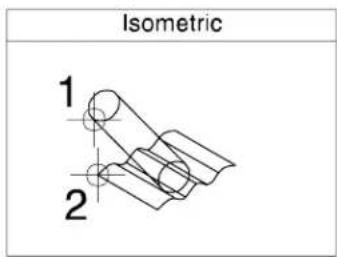
text_image
Isometric 1 2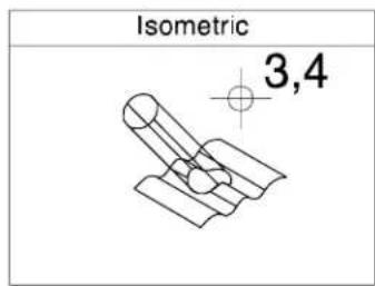
text_image
Isometric 3,4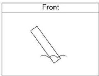
text_image
Front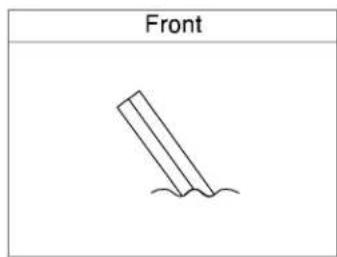
text_image
FrontWith Flip 1st turned on, the opposite portion of their first surface is retained after trimming.
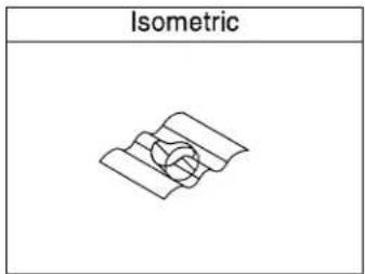
text_image
Isometric
text_image
FrontKey-in: CONSTRUCT TRIM
Project Trim

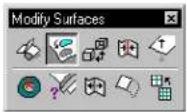
(3D only) Used to:
- Punch a hole in a surface by projecting a cutting profile.
- Project a B-spline curve onto a surface.
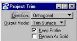
| Tool Setting | Effect |
| Direction | Sets the direction of the projection.Orthogonal—Projection is taken normal to the cutting profile.View—Projection is taken normal to the active view.Ve c t or —Direction of projection is determined by two points.Normal to Surface—Projection is taken normal to the plane of the surface being trimmed. |
| Output Mode | Sets the method used to trim the surface.Trim Surface—The region either inside or outside the projected curve is trimmed away. The identified portion of the surface is retained.Split Surface—The surface is divided into two regions, one inside the projected profile and the other outside the projected profile.Project Curve—Projects a B-spline curve on the surface. No boundary is created.Impose Onto—The profile curve is imposed onto the surface as a boundary (that is, a hole is cut into the surface). |
| Keep Profile | If on, the profile curve is retained. |
| Remain As Solid | If on, a trimmed solid remains as a SmartSolid.If off, a trimmed solid is converted to a SmartSurface. |
To trim a surface/solid by projecting a profile
- Select the Project Trim tool.
- Identify the surface/solid to trim, on a portion that is to
remain after the trimming operation.
- Identify the profile to project.
- Accept to create trim.
Trimming a surface (orthogonal to profile). Left: Identify the surface anywhere in the region that is to be retained (1) and the cutting profile (2). Right: Accept (3) to create the hole.
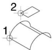
text_image
2 1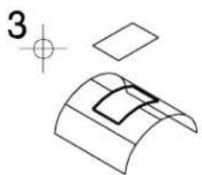
natural_image
Pure technical line drawing of a curved mechanical part with crosshair and dimension lines (no text or symbols)Alternative method — To trim a surface/solid by projecting a profile
- Select the Project Trim tool.
- Identify the surface/solid to trim, on a portion that is to remain after the trimming operation.
- Identify the profile to project.
- If Direction is set to Vector, enter first point to define vector direction.
- Enter second point to define vector direction and create trim.
Key-in: PROJECT TRIM
Convert 3D

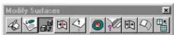
(3D only) Used to convert a solid to a simple surface (Type 18) or vice-versa.
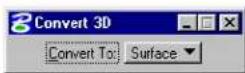
| Tool Setting | Effect |
| Convert To | Sets how the element is converted.Solid—Converts the element to a capped solid.Surface—Converts the element to a simple surface. |
To convert a solid to a surface
- Select the Convert 3D tool.
- Set Convert To to Surface.
- Select the element (solid).
- Accept the change.
Key-in: CONVERT 3D
Construct Stitch

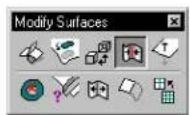
(3D only) Used to stitch two open surfaces (extruded surfaces, surfaces of revolution, B-spline surfaces or shapes) into one surface, along their abutting edges.
To stitch two surfaces together
- Select the Construct Stitch tool.
- Identify the first surface to be stitched.
- Identify the second surface to be stitched.
- Accept to create the stitched surface.
Left: Identify the first and second surfaces (1 and 2). Right: Accept to create the stitched surface (3).
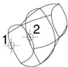
text_image
1 2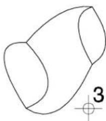
natural_image
Simple line drawing of a 3D geometric shape resembling a truncated cone or hourglass (no text or symbols)Key-in: CONSTRUCT STITCH
Change Normal Direction

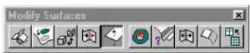
(3D only) Used to change the surface normal direction for a surface (cone, extruded surface, surface of revolution, or B-spline surface). Used in conjunction with other tools to control the way that elements are treated.
To change a surface's normal direction
- Select the Change Normal Direction tool.
- Identify the surface.
The surface normals display.
- Accept to change the direction of the surface normals.
Alternative method — To change a surface's normal direction
- Use the Element Selection tool to select the surface(s).
- Select the Change Normal Direction tool.
The normal direction is changed for the selected surface(s).
Key-in: CHANGE NORMAL
Untrim Surface

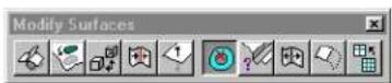
(3D only) Used to:
- Reverse the sense of trim boundaries in a B-spline surface or SmartSurface — that is, convert holes to surfaces and vice-versa.
- Remove one or more trim boundaries (holes) from a B-spline surface or SmartSurface.
Where a trim boundary is shared by two faces, along an edge, no change is made.
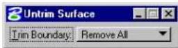
| Tool Setting | Effect |
| Trim Boundary | Sets the task to be performed.Reverse—Reverse the sense of the boundaries.Remove All—Remove all boundaries.Remove One—Remove one boundary. |
To reverse a surface boundary
- Select the Untrim Surface tool.
- In the Tool Settings window, set Trim Boundary to Reverse.
- Identify the surface.
- Accept the change.
Left: Identify the surface (1). Right: Accept to reuse the surface (2).
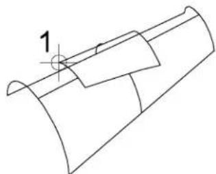
natural_image
Technical line drawing of a mechanical component with no visible text or symbols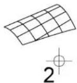
To remove trimmed regions
- Select the Untrim Surface tool.
- In the Tool Settings window, set Trim Boundary to Remove All or Remove One.
- Identify the B-spline surface.
- If Trim Boundary is set to Remove One, identify the boundary to remove.
- Accept the removal.
Left: Identify the surface (1). Right: Accept to remove the trimmed region (2).
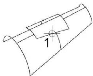
natural_image
Technical line drawing of a mechanical component with a curved base and a circular feature labeled '1' (no text or symbols beyond the number)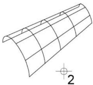
natural_image
Pure 3D wireframe diagram of a curved structural element with no text or symbols8-194 MicroStation User Guide
Key-in: UNTRIM SURFACE
Change to Active Surface Settings

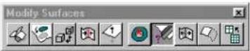
(3D only) Used to change a B-spline surface's B-spline attributes to the active B-spline settings, as follows:
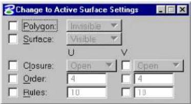
text_image
Change to Active Surface Settings Polygon: Invisible Surface: Visible U V Closure: Open Open Order: 4 4 Rules: 10 10| Tool Setting | Effect |
| Polygon | If on, changes the control net's display:Invisible—the control net is hidden.Visible—the control net is displayed. |
| Surface | If on, changes the surface's display:Invisible—the surface is hidden.Visible—the surface is displayed. |
| Closure | If on in the u- or v-direction, sets the surface to Open or Closed in that direction(s). The appearance is not changed, only the internal representation. |
| Order | If on in the u- or v-direction, sets the order in that direction. |
| Rules If on in the u- or v-direction, sets the number of rule lines in that direction. | |
| Preserve Shape | (Order on only) Preserves the original shape of the surface when the order is changed. |
To change B-spline attributes of a surface
- Select the Change to Active Surface Settings tool.
- Set the tool settings as desired.
- Identify the surface.
- Accept the changes.
Key-in: CHANGE SURFACE SETTINGS
Split Surface

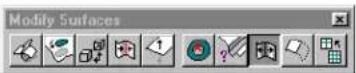
(3D only) Used to perform a partial delete on a surface or solid (shape, cone, sphere, extruded surface, surface of revolution, or B-spline surface) along its rule lines, in the U or V direction. Entering a reset, changes the direction of the splitting. The result of splitting the surface or solid is two B-spline surfaces.
To split a surface
- Select the Split Surface tool.
- Identify the surface.
- Select the end point of partial delete.
- (Optional) — Reset to change the direction of splitting.
- Select the second end point of splitting to complete the procedure.
Left: Identify the surface (1), then the proposed end point of the partial delete.
Right: Optionally reset to change the direction of the split, then define the end point and accept (3) to complete the split.
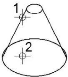
text_image
1 2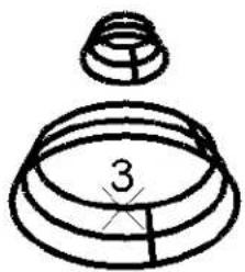
natural_image
Simple line drawing of a mechanical component with a top and bottom views, no text or symbols present.Key-in: SPLIT SURFACE
Extend Surface

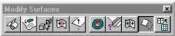
(3D only) Used to extend a surface (cone, extruded surface, surface of revolution, or B-spline surface) along one of its edges.
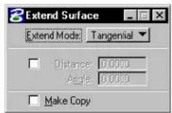
text_image
Extend Surface Extend Mode: Tangential Distance 0.0000 Angle 0.0000 Make Copy| Tool Setting | Effect |
| Tangential | If on, extension is tangent continuous at the joint of extension |
| By Angle | If on, extension is at an angle specified in the Angle field. |
| Distance | Sets the distance of the extension. |
| Angle | (By Angle on only) Sets the angle at which the extension is made. An angle of 0° creates a tangential extension. |
| Make Copy | The original surface is retained. |
To extend a surface
- Select the Extend Surface tool.
- Identify the surface near the edge to be extended.
- Adjust the settings if necessary.
- Accept the extension.
Key-in: EXTEND SURFACE
Rebuild Surface

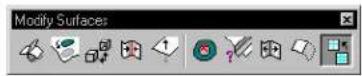
(3D only) Used to rebuild a B-spline surface.
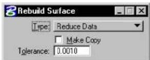
| Tool Setting | Effect |
| Type | Sets the type of rebuilt surface.Reduce Data—Used to remove unnecessary control points from a surface with tolerance.Rebuild with Tolerance—Used to remove cusp points on a surface by sampling a set of points from the surface and recreating it.Rebuild with Num Poles—Similar to Rebuild with Tolerance, but with a fixed number of poles as input.Swap UV—Swaps the U and V directions, so that U becomes V and vice versa.Reverse U—Reverses the U direction.Reverse V—Reverses the V direction.Reparameterize—Where a surface has all the knots concentrated in a certain region, such as to one side of the surface, it may be that the 0.5 knot is not near the center of the surface. This option attempts to rebuild the surface such that the 0.5 knot corresponds, as near as possible, to the center of the surface. |
| Make Copy | If on, the original surface is not deleted upon creation of the replacement surface. |
| To le r -ance | Sets the maximum distance allowed between the replacement surface and the original surface. To make the replacement surface appear identical to the original, even though its complexity is reduced, experiment with different Tolerance values. |
To reduce the number of poles in a B-spline surface
- Select the Rebuild Surface tool.
- From the Type option menu, choose Reduce Data.
- Identify a B-spline surface.
- Accept the reduction in the number of poles.
The number of control points reduced in both parametric U and V directions are displayed in the status field.
Identify a B-spline surface (1). Accept the reduction in the number of poles (2) to modify the surface.
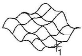
natural_image
Abstract wavy line pattern with no text or symbols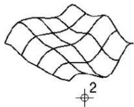
natural_image
Abstract wavy line pattern with a small crosshair symbol labeled '2' (no text or symbols beyond the label)5 points in U and 5 points in V directions are reduced
The number of control points reduced in the U and V directions are displayed in the status field.
Key-in: REBUILD SURFACE

To check the number of control points in a B-spline surface, use the Element Information tool in the Primary Tools tool box or choose Information from the Element menu.
Fillet Surfaces tool box
The tools in the Fillet Surfaces tool box are used to create fillets between surfaces, and to join surfaces by blending.
| To | Select in the Fillet Surfaces tool box |
| Construct a fillet of constant radius between two surfaces. |  Fillet Surfaces (see page 8-202) Fillet Surfaces (see page 8-202) |
| Construct a blend surface from two surfaces. |  Blend Surfaces (see page 8-205) Blend Surfaces (see page 8-205) |
| Construct a blend surface between two B-spline surfaces along their rail curves. |  Blend Surface Between Rail Curves (see page 8-207) Blend Surface Between Rail Curves (see page 8-207) |
Key-in: DIALOG TOOLBOX 3DFILLET [OFF | ON | TOGGLE]
Fillet Surfaces

(3D only) Used to create a 3D fillet between two surfaces (shapes, cones, extruded surfaces, surfaces of revolution, or
B-spline surfaces) by sweeping an arc of constant radius along the common intersection curve — commonly referred to as a constant radius rolling ball fillet. The fillet is created in the area pointed to by the surface normals of both surfaces.
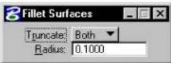
| Tool Setting | Effect |
| Truncate | Defines which surface(s) are to be truncated:Both—Both surfaces are trimmed.Single—The first surface identified is trimmed.None—Neither surface is trimmed. |
| Radius Sets the fillet's radius. | |
To place a fillet between two surfaces
-
(Optional) — Use the Change Normal Direction tool to set the normal directions for both surfaces.
-
Select the Fillet Surfaces tool.
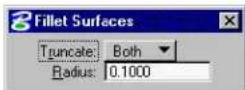
- From the Truncate option menu, choose a truncating option.
- In the Radius field, key in the required radius.
- Identify the first surface.
The surface normal orientation displays.
- Identify the second surface.
The surface normal orientation displays.
- Accept to view the fillet.
The fillet displays.
- Accept to create the fillet.
Creating a fillet between two usfaces.
Left: Identify the two surfaces (1 and 2).
Right: Accept (3) to view the fillet, then accept (4) to create the fillet.
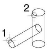
text_image
1 2
Key-in: FILLET SURFACES
Blend Surfaces

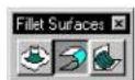
(3D only) Used to construct a blend between two elements (extruded surfaces, surfaces of revolution, cones, or B-spline surfaces) with a specified order of continuity. The resulting B-spline surface consists of the trimmed original elements and a transition connecting them.
The direction of the first and last tangents of the transition is the direction of the tangents of the original elements at their trimmed edges. The relative magnitudes of these tangents can be adjusted to achieve the desired blend.
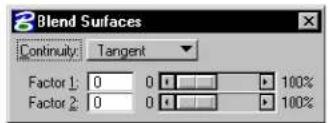
text_image
Blend Surfaces Continuity: Tangent Factor 1: 0 0 100% Factor 2: 0 0 100%| Tool Setting | Effect |
| Continuity | Sets the order of continuity — Position, Tangent, or Curvature. |
| Factor 1 | Sets the magnitude of the initial tangent. |
| Factor 2 | Sets the magnitude of the final tangent. |
To construct a blend between two surfaces
- Select the Blend Surfaces tool.
- Identify the point on the first element where the blend is to start.
- Identify the edge of the first element to trim.
- Identify the point on the second element where the blend is to end.
- Identify the edge of the second element to trim.
- (Optional) — Adjust the settings to achieve a satisfactory blend.
- Accept the blend.
text_image
1 2 4 3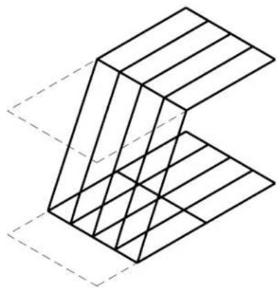
natural_image
Isometric line drawing of a 3D geometric structure with intersecting planes (no text or symbols)Constructing a blend surface with Continuity set to Tangent.
Left: Identify the blend start point on first element (1) and the edge to be trimmed back (2), the blend endpoint on the second element (3), and the edge to be trimmed back (4). Right: The proposed blend (before accepting).
After adjusting the Factor 1 and Factor 2 settings to suit.
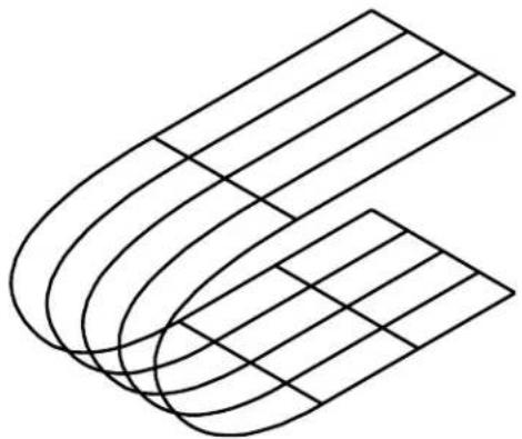
natural_image
Abstract geometric line drawing with curved and straight lines forming a 3D shape (no text or symbols)Key-in: BLEND SURFACE
Blend Surface Between Rail Curves

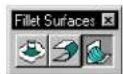
(3D only) Used to construct a blending B-spline surface between two surfaces (extruded surfaces, surfaces of revolution, cones, or B-spline surfaces) along their rail curves. A rail curve is an element (line, arc, line string, ellipse, complex shape, complex chain, or B-spline curve) lying on the surface. ^4
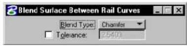
| Tool Setting | Effect |
| Blend Type | Sets the type of blendRound—smooth circular blend.Chamfer—chamfer blend. |
| To le r -ance | Determines the number of (sampled) points used to create the blend. |
To construct a blending surface between two B-spline surfaces along their rail curves
- Select the Blend Surface Between Rail Curves tool.
- Identify the first B-spline surface.
- Identify the first rail curve.
-
Identify the second rail curve.
-
Enter a data point to display the blending surface.
- Accept the blending surface.
Creating a blend surface between rail curves. Left Identify first surface (1), first rail curve (2), then second surface (3) and second rail curve (4) Right: Accept (5) to create the rail curve (Blend Typ: Chamfer in this example).
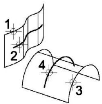
text_image
1 2 4 3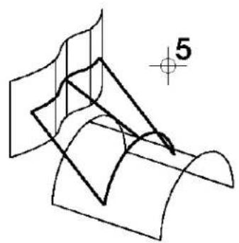
natural_image
Pure geometric diagram showing intersecting planes and curves without any text, numbers, or symbolsKey-in: BLEND RAILS

If a rail curve is closed, use the Change Element Direction (see page 7-116) tool in the Modify Curves tool box to re-orient the curve to match the direction and starting point of the other rail curve.
3D Queries tool box
Tools in the 3D Queries tool box are used to extract curves from B-spline surfaces.

| To | Select in the 3DQueries tool box |
| Graphically and numerically evaluatethe attributes of a B-spline surface atgiven locations on the surface. |  _Evaluate Surface (seepage 8-210) _Evaluate Surface (seepage 8-210) |
| Visualize the curvature of a curve orGaussian curvature of a surface. |  _Analyze Curvature(see page 8-215) _Analyze Curvature(see page 8-215) |
Key-in: DIALOG TOOLBOX EXTRACT [OFF | ON | TOGGLE]
Evaluate Surface


(3D only) Used to graphically and numerically evaluate attributes of a B-spline surface, other than order, poles, and knots, at given locations on the surface. There are four ways to define locations on a surface, and two output options.
The attributes that can be computed are points, tangents, and
normal directions. Computed attributes can be used as reference points or reference lines for other purposes.
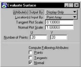
text_image
Evaluate Surface Attribute(s) Output By: Display Only Location(s) Input By: Point Array Tangent Plot Scale: 0.100000 Normal Plot Scale: 1.000000 U V Number of Points: 20 20 Compute Following Attributes: Points Tangents Normal| Tool Setting | Effect |
| Attribute(s)OutputBy | Set sthemethoddusedtooutputtheputed attributes:Display OnlySave In File—The attributes are saved in theactive design file with the same graphic groupnumber for easy manipulation. |
| Location(s)Input By | Sets the manner in which the locations on the surface are defined:Enter Data Point—interactively define a single location on the surface.Parameter—using the Parameter Value U and V settings. The values, which must be in the range 0–1, specify the location from the domain to map to the displayed object. Within MicroStation, the domain is from 0.0 to 1.0.Dist[ance] Along Curve—using the Dist From Start(%) U and V settings. The values are each a percentage of the total length of the u or v curve on the surface. For example, to extract the tangent direction of a surface at its middle point, set Dist. From Start(%) U and V each to 50.Point Array option—using the Number of Points U and V settings. The values are the number of evenly spaced locations on the u and v curves, respectively. For example, to evaluate at 200 evenly spaced locations on the surface, set Number of Points U to 10 and Number of Points V to 20. |
| Tangent Plot Scale | Sets the scale factor applied to the magnitude display. If set to 1.0, the computed tangents will be the true derivative vector — that is, the tangent direction with the magnitude. |
| Normal Plot Scale | Sets the scale factor applied to the perpendicular line segments in Normal output. If set to 1.0, the true normal vector is displayed — that is, the direction plus its true magnitude. |
| Parameter Value U/V | Sets the parameter values applicable to the Parameter option for defining locations on the surface; see Location(s) Input By above. |
| Dist[ance] From Start(%) U/V | Sets the distance values applicable to the Dist. Along Curve option for defining locations on the surface; see Location(s) Input By above. |
| Number of Points U/V | Sets the numeric values applicable to the Point Array option for defining locations on the surface; see Location(s) Input By above. |
| [Compute]Points | If on, the points on the surface at which evaluation is performed are displayed in the output.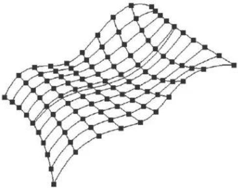 |
| [Compute]Tangents | If on, the surface's tangents are computed. In the context of this tool's operation, a tangent is computed as the partial derivatives of the surface in both parametric u and v directions.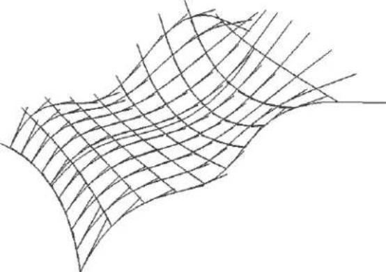 |
| [Compute] Normal | If on, the surface's normal directions are computed. 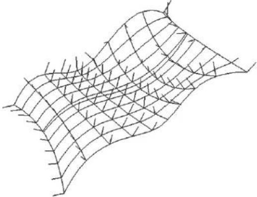 |
To evaluate a B-spline surface
- Select the Evaluate Surface tool.
- Identify the surface.
If Location(s) Input By is set to Enter Data Point, this data point also determines the location on the surface at which to evaluate.
- Accept the surface.
The surface is evaluated, and the desired attributes are computed and output.
Key-in: EVALUATE SURFACE
This tool can also be used to evaluate 3D primitive surfaces.
Analyze Curvature


(3D only) Used to visualize the curvature of a curve or Gaussian curvature of a surface.
Tovisualizethecurvatureofacurveorsurface
-
Select the curve or surface.
-
Select the Analyze Curvature tool.
The element is rendered with coloring according to its curvature: Sharply curved regions are displayed in purple while flat regions are displayed in red; intermediate regions are displayed using a range of colors in between those extremes.
Alternative method — To visualize the curvature of a curve or surface
-
Select the Analyze Curvature tool.
-
Identify the curve or surface.
The element is rendered with coloring according to its curvature.
Key-in: ANALYZE CURVATURE RELATIVE
Using Cells in 3D
Cells are used in 3D modeling in a manner similar to 2D (see "Using Cells" on page 5-1). 3D-specific details are covered in this section.
You can place a 2D cell in a 3D model and vice-versa. When a 3D cell is placed in a 2D model, it is placed as a Top view orientation. That is, with its X and Y design axes matching that of the 2D model's X and Y design axes.
Creating 3D cells
The procedure for creating a cell in 3D is similar to that in 2D (see "Creating and Editing Cells" on page 5-6), with these differences:
• 3D cells, along with their 2D counterparts, are simply models in a DGN file that have the setting Can be placed as a cell turned on.
- In 3D, the cell retains the orientation in which it was created. For example, a cell created in a Top view always is placed as though it is a Top view. That is, its length and width always would be along the x and y axes of the view (if AccuDraw is not active) or the AccuDraw drawing plane (when AccuDraw is used). Normally, cells should be created in one of the Orthogonal views (see page 8-7) to simplify future placement.
- 3D cells are created in a volume determined by the fence area and the view's Display Depth.

It is a good idea to create separate models of those objects that you later want to use as cells.
Patterning in 3D
In 3D, as is the case in 2D, any element that is closed, planar, and with its Area tool setting as solid, can be patterned. The Active Pattern Angle sets the angle of the pattern in the view in which the element is identified. If AccuDraw is active, the current AccuDraw drawing plane is used in defining this angle. If the element is parallel to the view, the actual pattern angle and the apparent angle are the same.
Index
2 D = ....= 8 - 7 or i g i n = ....= 3 - 32
3D place circle and =....= 3-67
AccuDraw's drawing planein=....po=18-59o ordinates .......=3-41
concepts....=8-p2op-upcalculator=....=3-44
Construct=....=8-100etings=....=3-37
create=cells=in=....=8-216 snapdivisor....=3-66
data=points=....=8-64 tolerances hortcut....=3-40
drawingin....=8-5 ^7 unitrounding=....=3-57
editprimitive=....=8-w143ndow=....=3-36
M a i n = . . . . . . . . . . . . . . . . . . . . . . . . . . . . . . . . . . . . . . . . . . . . . . . . . . . . . . . . . . . . . . . 8-8ACCUDRAW=BUMP=TOOLSETTING=.=.=.3-73
manipulating/modifying=elements=in=.=8-73 ACCUDRAW=SETTINGS=CONTEXTSENS=ON
Modify=....=8-11&ey-in....=3-43
orthogonalviews.....ACCUDRAW=SETTINGS=INDEXTOL=.==.=3-40
panningviewsin....=A el5u S nap=....=3-2
placing elements in....=8e58ings=....=3-15
Primitives=.....=8-688=.....=8-66,7-135,=7-137
Queries=....=8-2Alive
selecting=elements=in=....=8-74 color=....=1-4,=1-13
tentativepoints....=8-64 facesettings, change to....=8-195
using the fence in =.....A8i75-angle
Utility = 8-144 pop-upcalculator=....=3-44
3D=View=Control A C T I V E A N G L E S k e y - i n ..... = 7-106
ChangeView Perspective....A€8-2VECELLkey-in=....=5-15
Navigate=Camera = 8-36 Active color = 2-2
Show Active Depth = ....A=8t-27e Depth....=8-5,=8-57
move=....=8-27
A s et = ....= 8-25
AC = key - in = 5 - set by key - in = 8 - 26
AccuDraw=....=3-1.=3-s2how=....=8-28
3 D operation ....=8 Active level ....1-13
ACS and = 8-69 set = . . . . . . . . . . . . . . . . . . . . . . . . . . . . . . . . . . . . . . . . . . . . . . . . . . . . . . . . . . . . . . . . . . . 1 - 2
activate=....=3-30activelinestyle=....=2-6
and Place Arc= = A-6#ivelineweight....=2-4
and PlaceBlock=AC TIVELINESTYLESCALEkey-in=...=4-66
and=Place=Ellipse=....=3-69ACTIVEMODEkey-in....=7-107
and PlaceSmartLine=ACTIVEPATTERN MATCH key-in ..... 5-63
compass=....=3-31,=3-59Active=point
d e a c t i v a t e = ....= 3 s e t = ....= 2-53
d e f a u l t s = ....= 3-50 t t i n g s g r o u p c o m p o n e n t = ....= 2-77
drawing plane = 3-34 ACTIVERCELL key - in = 5-15
drawing=plane=orientation ..... = 3-62Active=scale
keyboard shortcuts=....=3-48,93p73up calculator=....=3-44
Index

ACTIVESTYLE key - in = ....Area2 - 8
ACTIVETERMINATORkey - in = .....fill= 5-23.....= 4-63
ACTIVE TEXT key - in =...... Array72
ACTIVE=TOLERANCE=
ACTIVETSCALEkey-in=....r=5e-2angularcoordinates=....=4-52
ACTIVE=ZDEPTH=ABSOLUTE=key-in=.=.=8-26 type = ........ = 4-52
ACTIVE=ZDEPTH=RELATIVE=key-in=.=.=8-27ARRAY=ICON=key-in ........=4-55
Add ARRAY=POLAR=key-in=....4-55
to Graphic Group =......AR2Y=RECTANGULAR=key-in=......=4-55
Align Arrowhead = 5-23
Edges....=4-50 Associate
Faces=....=8-146multi-linewithanotherelement=....=7-51
ALIGNEDGE key - in = .... Association
ALIGNFACE key·in=....=8+16p....4-83
Analyze of elements = 7-50
Curvature = 8-215 shared=cells=7-51
ANALYZE=CURVATURE=RELATIVE point=....=4-83
key-in....=8-21Associative=pattern....=5-52
Angle drop 4-85
between lines = ....= 3410dh
Apply Clip Volume To View =......reference......= 6-31
A R = k e y - i n = .... 5-15 references=.... = 6 - 2
Arc ATTACHACSkey-in=....=7-144
by=endpoint,=center=and=sweep=angle=.=2-67Attachments
elliptical=(180° s w e e p a n g l e) = .....= 2l-50 at el ost = .....6-11
elliptical=(90° s w e e p a n g l e) =......A#r#dutes
extend/shortentointersection...ele-mel04=....=2-1
thru=4-105 view =2-1
modify angle = ·s·s= A x 7 Biary Coordinate System (ACS) ..... 8-66,
modify axis =....2-74-135
modifyradius=....=2A72cuDrawand....=8-69
place with Accu Draw = ...... a 3-68ve = ...... = 8-72
tangentsegments....=3-170gnwithelement=....=7-139
Arcs=....=2-66a lign with view coordinates....=7-141
Area attach = 8-71, = 7-144
active(solid/hole)=....2-13b=46a tapoints....=7-140
changeelementtoactive=......cy46h drical....=8-67
changefencecontentstoactive=...define4-61....=7-135,=7-139
closedelement = 3-10fining= = 8-71
enclosedbyelements=......=i3l-d03tify=......=8-72
enclosedbyfence=....=3n103keactive....=8-71
measure....=3-103moveorigin....7-143
ofelementdifference=....p3a03elock=....8-72
ofelementintersection....p3-d03sioninputusing=....=8-73
ofelementunion....=3-103ctangular=....=8-66
pattern=....=5-29 rotatefromtoporientation....=7-142
Index
| save=......=7-135place with Accu Draw=......=3-69select=and=attach=......=7-14Boreline=......=8-64spherical=......=8-68esitelock=......=8-74triaddisplay=......=7-135type=......=8-66Auxiliary=Coordinates=......=7-136CalculateAZ=key-in=......=8-26curve=......=7-103CalculateCurve=......=7-68,=7-101BCalculationsB-splineofcurve=......=7-61closed......=7-65alculator=......=3-44controlpolygon=......=7-60ame64curve=......=7-60AdvancedMode......=8-47order=......=7-60,=7-64nove=......=8-33periodic=......=7-65settings=......=8-29poles=......=7-60AMERANAVIGATEkey-in=......=8-49surface......=8-162atenary=......=7-101B-splineCurves=......Ca7=711-Rom=curve=......=7-63clean=up=those=with=large=number=of=controlCell=......=5-1points=......=7-112ndlevels=......=5-12data=points=to=place=......=7-79associateshared=......=7-51from=data=points=with=tangent=directions=7-84create......=5-7,=8-216topassthroughelementvertices......define7=84gin=......=5-22B-spline=surfacesdelete fromlibrary=......=5-9basedonelementvertices=......d=8-172cd......=5-64create......=8-169designateactive=......=5-11evaluate......=8-214dimension-driven=......=5-64evaluateattributes=......d8e210association......=4-83Fence=Stretch=function=and=......=4-20editname/description......=5-9helical-shaped=......=8-179graphic=......=5-7reducepoles=......=8-200entify=......=5-23BézierCurve......=7-67instanceofshared......=5-13Bisector......=3-08igin=......=5-1,=5-7,=5-22angle......=2-31orphan=......=7-3Blendpattern=......=5-31,=5-36Curves=......=7-119laceactive=......=5-20SurfaceBetweenRailCurves=......p≠8e207ineterminator......=5-23Surfaces......=8-205point=......=5-7BLENDCURVEkey-in=......=7-e120tion=......=5-7BLENDRAILSkey-in=......=8-e200ct=......=5-20BLENDSURFACEkey-in=......=8e207ctor=......=5-14Blocksettings=......=5-143D(slab)=8-53settingsgroupcomponent=......=2-77isometric=......=7-55ared=......=5-13,=7-51place=......=2-44symbology=......=5-7 |
Index
terminator....=5-23 Active Area....=4-61
type(graphic/point)=....toActiveFill Type....4-63
CellLibrary=....€CHANGEFENCEkey-in....=4-61
3D=....=8-216CHANGEFILL=....=4-64
attach=....=5-3CHANGEICONkey-in=....=4-61
browsecontentsof=....CHANGE=LINESTYLE=SCALE=key-in=.,=.=4-65
create....=5CHANGEMLINEkey-in....=4-67
Cell=Settings
CHANGE=SURFACE=NORMAL=key-in.=8-192
activecell=....=5CHANGE=SURFACE=SETTINGS=key-in=8-196
active=cell=(for=placement)=....=5-1CHANGE=VIEW=DISPLAYMODE=key-in=.8-35
active=pattern....=5-52CHANGE=VIEW=PERSPECTIVE=key-in=.8-22
Cells=....=5-5,=5-CHOSE ELEMENTkey-in....=4-4
associatingshared=....Circle-51
replace....=5-25bycenter=....=2-36
Chain=....=7-12bydiameter=....=2-36
complex=....=7bedge=....=2-36
Chamfer
byradius....=2-36
construct=....=4-hiso metric=....7-57
Edges....=8-140 measureradius=....=3-100
CHAMFEREDGESkey-in=....=p8i43e withAccuDraw=....=3-67
CHAMFERkey-in=....=4+10dius=....=3-100
Change
Clip
Attributes ....=4-56 optimizedfence=....=3-84
element=attributes=....=4-61 Clip Volume=....=8-49
ElementAttributes....Cl=i2-pingmask=....=6-33
Multi-line=to=Active=Definition=....=4-6Clipping-plane
NormalDirection=....=8defbe=for=references....=6-34
SmartSolidDisplay=....Gl8sel51
SurfaceNormal....=8-192ement=....=2-20,=2-26
toactivearea=....=C-6IOSE ELEMENT=....=2-47,=7-87
toActiveArea(Solid/Hole)....=C7L0-S-E ELEMENTkey-in....=2-20,=2-26
toActiveCurveSettings=....=7-C5o5-dploning
to=Active=Solid—or=Surface Status=....=8-190after/removing faces/features—from
toActiveSurfaceSettings=....=8-59s8-195=....=8-122
ViewPerspective....€M21=....=5-20
CHANGEAREAkey-in....€4+62r=....=1-4,=1-13
CHANGEBREPDISPLAYkey-in=.....a-c8-t53e =.....2-3thru1-4,=1-13
CHANGECOLORFILLkey-in.....e-l4a64geelementtoactive=.....=4-58
CHANGECOLOROUTLINE....=c4a64ngefencecontentstoactive=.....=4-58
CHANGECURVEkey-in=.....fill12......=4-63
CHANGE=DIRECTION=key-in=.....=7-117 fill(area=.....=2-13)
Change=node match active to element ....4-68 thru 4-69
toActiveLevel=.....=4p58lette ....=1-4,=1-13
Change=Element selectelements by.....=7-133
Attributes .... =2-9, =4-58 table=. ... =2 - 2
Direction=. ... =7-Mvalue=. ... =1-4, =1-13
i-4=MicroStation User Guide
Index
Compass OpenCrossJoint 7-36
AccuDraw 3-31OpenTeeJoint 7-41
Complex Parabolic Fillet 7-7
chain 7-2ParametricLineString 7-108
shape 4-80 Revolution 8-107
string 4-80SkinSolid/Surface 8-174
ComplexChain.... 4-80titch.... 8-191
create automatically.... 7-12 Surface by Edges.... 8-166
createmanually 7SurfacebySectionorNetwork 8-163
Complex Element surfaceorsolidofprojection...
drop status 7-2, 4-80 Surface or Solid of Revolution 8-107
drop status of fence contents 4–24 Tr i m 8–184
Complex Shape 7 Union 8-128
create automatically.... 7-15 CONSTRUCT ARCS INTERPOLATION
createmanually 7k15y-in 7-90
difference of elements 7–18 CONSTRUCT BISECTOR ANGLE key-in 2–32
flood fill to create 7-18 CONSTRUCTBSPLINECURVE 7-82
intersectionofelements ....C.ONSIBRUCTCUTkey-in....8-137
unionofelements ...... CONSTRUCT DIFFERENCE key-in ... 8–134
Cone CONSTRUCT EXTRUDE ALONG
place 8-53, 8-93 key-in 8-113
Configuration variables CONSTRUCTFACEKey-in 8-161
MS_RFDIR 6CONSTRUCT INTERSECTION key-in . 8-132
Conicsection.... 7-66,7G91NSTRUCTLINEAAkey-in .... 2-35
Construct CONSTRUCT LINE MINIMUM key-in .. 2-33
PointsAlong Element....CONSTRUCT OFFSET CURVE key-in .. 7-98
PointsBetweenDataPoints ..... CONSTRUCT OFFSET SURFACE
ActivePointatIntersection .....key2-i61..... 8-182
Angle Bisector..... 23NSTRUCT PARAMETRIC CURVE
Array 4-52 key-in 7-108
B-splinesurfacebycross-section CONSTR-074PARAMETRIC LINESTRING
Chamfer 4-118 key-in 7-108
Circular Fillet CONSTRUCT POINT ALONG key-in ... 2-63
Closed Cross Joint ...... CONSTRUCT POINT BETWEEN key-in 2–59
Closed Tee Joint 60 CONSTRUCT POINT DISTANCE key-in 2-65
CornerJoint 7G CONSTRUCT POINT INTERSECTION
Difference 8-13Key-in 2-62
Facet 8-15 CONSTRUCT POINT PROJECT key-in . 2-60
HelicalSurface 8-07NSTRUCTSHELLkey-in 8-115
InterpolationbyArcs 7-6607N89 TRUCTSTITCHkey-in 8-191
Intersection.... 8-03NSTRUCT SURFACE CROSSSECTION
LineatActiveAngle.... 2k38y - in.... 8-166
Merged Cross Joint ...... CONSTRUCT SURFACE EDGE key-in . 8–168
Merged Tee Joint ...... CONSTRUCT SURFACE HELICAL
Minimum Distance Line ..... l2e32-in..... 8-180
Offset Surface 80NSTRUCT SURFACE PROJECTION
Index
key-in.... 8-10CREATE REGION INTERSECTION.... 7-22
CONSTRUCT SURFACE REVOLUTION CREATE REGION UNION 7-22
key-in.... 8-10CREATE SHAPE AUTOMATIC key-in .. 7-17
CONSTRUCT SURFACE SKIN key-in . 8-175 CREATE SHAPE MANUAL key-in ..... 7-16
CONSTRUCT SURFACE TRACE key-in 8-178 Create Surfaces 8-162
CONSTRUCTTHICKENkey-in....Cross108nt 7-35,7-37
CONSTRUCTTRIMkey-in.....C8-d85 hatchArea..... 5-31, 5-49
CONSTRUCTUNIONkey-in ....CROSSHATCH DIFFERENCE key-in ... 5-51
Control camera CROSSHATCH ELEMENT key-in ..... 5-51
tilt 8-38CROSSHATCH FENCE key-in 5-51
Controlpoints.... 7-ROSSHATCH FLOOD key-in .... 5-51
CONVERT BSPLINE key-in 7-118 CROSSHATCH ICON key-in 5-51
Convert Element CROSSHATCH INTERSECTION key-in . 5-51
t o B - s p l i n e.... 7-1CROSSHATCH POINTS key-in .... 5-51
CoonsPatch 8-1GROSSHATCH UNION key-in 5-51
oordinate Curve 7-59
view 8-10 3DB-spline 7-95
Coordinates a n a l y z e 8-215
AccuDraw 3-3B-spline 7-60, 7-75, 7-91, 7-94
Copy Bézier 7-59, 7-67, 7-85
element 4-26,3-77blend B-spline 7-119
elementtodifferentlevel ..... calculate based on formula .... 7-68, 7-101
element, parallel.... 4addulation methods .... 7-61
fencecontents 4-28mull-Rom 7-63
reference 6-18 thru 6-20 change to active settings 7-110
Reference Attachment 6–37 composite 7–66, 7–85
Copy Element conic section 7-66
rectangulararray ..... do52vertelementtoB-spline ..... 7-117
topolararray 4-5 derive from existing 7-72
using fence 4-2 digitizing 7-148
COPYELEMENTkey-in....4thensionality....7-71
COPYICONkey-in 4-d8s play 7-64
COPY PARALLEL DISTANCE ..... 4–33 ed i te qu at i on ..... 7–69
COPY PARALLEL KEYIN .... 4x32nd .... 4-113 thru 7-114
CornerJoint 7-43 r mula 7-68, 7-101
Create functions 7-72
cell 8-216 hyperbola 7-66
celllibrary.... 5-least squares approximation .... 7-62
ComplexChain 7-112brary 7-68,7-101
Complex Shape 7-1b5k equation 7-70
Region(complex shape) .....m4td8settings ..... 4-75
relativeoffset 3m15dify 7-63
CREATE CHAIN AUTOMATIC 7-15 non-planar 8-52
CREATE CHAIN MANUAL key-in ..... 7-15 parabola ..... 7-66
CREATE REGION DIFFERENCE key-in 7-22 parametric....7-107 thru 7-108
CREATE REGION FLOOD 7-22 partial ellipse 7-66
Index
point=.....=2-29,=7-60precision=.....=3-91
pre-defined=.....=7-10lative=.....=3-93
reduce B-spline polecount=.....Data=Pdln2
space=.....=8-52angle=.....=3-56
stream=.....=2-29,=7-D48a=points
tolerance=.....=7-62place B-spline curve=.....=7-79
transitionalspiral.....=with60tangent=directions=for=B-spline=curve
Curve Calculator=.....=7-67,=7-d8ation=.....=7-83
Curve-type=elements    DD=.....=8-24
flatten=.....=7-124 Defaults
Curves.....=7-74AccuDraw=.....=3-50
Extract Iso-parametric Lines....Define=7-99
Custom=line=style    auxiliary=coordinate=system=.....=7-139
set global factor=.....=4u6diary=coordinate=system=(ACS) .==.=7-135
Custom Line Style=.....€2-17Origin=.....=5-7,=5-22
active=.....=2-multi-linejoints=.....=7-30
definition=.....=2-6 Reference=Back=Clipping=Plane=.....=6-34
modifiers=.....=2Reference Clipping Boundary .....6-32
name=.....=2-8Reference=Clipping=Mask=.....=6-33
pointsymbol=.....=2Reference Front Clipping Plane .....6-35
scalefactor=.....=2-6Define=ACS
stroke=pattern=.....=2-6 Aligned with Element=.....=7-139
width=.....=2-6,=2-9 Aligned with View =.....=7-141
Cut    ByPoints ..... = 7-135, =7-140
All Component Lines =.....DEFINE ACS ELEMENT key-in ..... 7-140
IntelliTrim =..... =4-107 DEFINE ACS POINTS key-in ..... 7-141
Single Component Line =.....D.E.F-BNE AC S VIEW key -in ..... =7-142
Solid ..... =8-13D E FINE C E L L O R I G I N k e y -in =..... =5-22
CUTALL key -in ..... =7Deform=B-spline=curve=..... =7-126
CUTSINGLE key -in =..... D5f88n=Curve =..... =7-126
Cylinder    D E F O R M C U R V E key -in =..... =7-127
place =..... =8-53, =8-Belete
D    AccuDraw shortcuts =..... =3-50
    Fence Contents ..... 4-23, 3-82
Data =button    Part of El ement =..... =4-101
3D =..... =8-64 Pattern ..... =5-64
Data =point    pop-up calculator variables ..... 3-48
3D =..... =8-64 Reference=Clipping=Mask=..... =6-33
absolute ..... =3-92Vertex ..... 4-115
along design plane axes =.....DELETE PARTIAL key-in ..... 4-102
along drawing plane axes ..... DEHSEE PATTERN key-in ..... 5-64
along view axes ..... =3DELE TE VER T E X key -in =..... =4-115
angle =..... =3-Be pth
coordinatesystem ..... =3Bcive =..... =8-5
distance =..... =3-55, =3-BEP TH A C T I V E key -in ..... =8-27
DEPTH DISPLAY key-in ..... 8-25
Index

| Designcube=......=Digitizing=......=7-144 | |
| Detach | curve......=2-29,=7-148 |
| reference=......=6-25 | line string=......=2-27,=7-148 |
| Reference=......=6-42 | panningwhiledigitizing......=7-148 |
| DIALOG=REFERENCE=key-in......=6-30 | setup......=7-144 |
| DIALOG=TOOLBOX=3DCONSTRUCT | tablet=......=7-144 |
| key-in......=8-10 | Digitizing=Tablet |
| DIALOG=TOOLBOX=3DDRAWING=key-in=8-83 | mapto design plane coordinates......=7-147 |
| DIALOG=TOOLBOX=3DFILLET=key-in=8-202 | partition=......=7-145 |
| DIALOG=TOOLBOX=3DFREEFORM | Dimension |
| key-in......=8-163 | drop......=4-87 |
| DIALOG=TOOLBOX=3DMODIFY=key-in=8-120 | dropassociation=......=4-83 |
| DIALOG=TOOLBOX=3DMODSURF | insertextensionline......=4-113 |
| key-in......=8-184 | match=settings=......=4-74 |
| DIALOG=TOOLBOX=3DQUERY=key-in=8-145 | removeextensionline......=4-115 |
| DIALOG=TOOLBOX=3DTOOLS=key-in=8-82 | Dimension-drivenCell=......=5-64 |
| DIALOG TOOLBOXACS key-in=......m7-d38y=......=5-65 | |
| DIALOG TOOLBOXAR C key-in=......p±2e66......=5-65 | |
| DIALOG TOOLBOXCELLS key-in=.Directi5n15 | |
| DIALOG=TOOLBOX=CHANGE=key-in=8-192 | change normal......=8-192 |
| DIALOG=TOOLBOX=CURVECREATE | compute for B-splinesurface......=8-210 |
| key-in......=7-7 | Display |
| DIALOG=TOOLBOX=CURVEMODIFY | change Smart Solid......=8-151 |
| key-in......=7-11 | display depth......=8-5 |
| DIALOG TOOLBOX DROP key-in=......set=4-79......=8-22 | |
| DIALOG=TOOLBOX=EXTRACT=key-in=8-210 | show=......=8-27 |
| DIALOG TOOLBOX FENCE key-in..Display=Depth | |
| DIALOG TOOLBOX FILLET key-in..move=6......=8-25 | |
| DIALOG TOOLBOX GROUPS key-in Display=Mode | |
| DIALOG=TOOLBOX=ISOMETRIC=key-in 7-55 changing......=8-35 | |
| DIALOG TOOLBOX JOINTS key-in=Dis.p=17a-y volume......=8-49 | |
| DIALOG TOOLBOX LINEAR key-in Distance=16 | |
| DIALOG=TOOLBOX=MANIPULATE | along element......=3-97 |
| key-in......=4-26 between points......=3-97 | |
| DIALOG TOOLBOX MATCH key-in=......me4-s7re......=3-97 | |
| DIALOG=TOOLBOX MEASURE=key-in=3-96 | minimumbetween elements......=3-97 |
| DIALOG TOOLBOX MODIFY key-in..p=4-90dicularfrom element......=3-97 | |
| DIALOG=TOOLBOX PATTERNS=key-in=5-40 Donut=......=8-54,=8-94 | |
| DIALOG TOOLBOX POINTS key-in=D P:=2-55......=8-24 | |
| DIALOG TOOLBOX POLYGONS key-in .2-43 Drawing | |
| DIALOG=TOOLBOX SELECTION=key-in=4-2 | technique......=3-1 |
| DIALOG=TOOLBOX SURFACE=key-in=8-162 | Drawingplane......=3-34 |
| DIALOG=TOOLBOX=VIEWCONTROL | coordinatesystem......=3-35,=8-70 |
| key-in......=8-19 in 3 D......=8-59 | |
| Difference | indicator=......=3-32 |
| construct......=8-13 | ockaxis......=3-55 |
| orientation=......=B162TPRIMITIVEkey-in=......=8-144origin=......=3-32,=3Elementrotateaxes......=8-60,=3-63sociation......=7-50Drop=......=4-78attributes=......=2-1,=2-13Association=......=4b83undary=......=8-55AssociativePattern=......=colm85lex......=7-2Complex=Status=......=7-2,=4-80filter=display......=7-133Complex=Status=of=Fence=Contents=......=4-24handles=......=3-77DimensionElement=......=7-2,=7-10dentify=......=6-15,=8-74Element......=4-85sinsolid=......=7-5FromGraphicGroup=......=i7a-23rsection=......3-8Line=String/Shape=Status=......=4-81keypoint=......=3-12LineStyle=......=4-84anipulate=......3-77Multi-line=......=4-86manipulationtools=......=4-1Multi-lines......=7-32menu=......=2-1Text=......=4-82midpoint=......3-8DROPASSOCIATIONkey-in=......=m4d84icationtools=......=4-1DROPCOMPLEXkey-in......=in-80dify=......=3-77,=4-90DROPDIMENSIONkey-in......=m4e87fygeometry=......=3-77DROPELEMENTkey-in......=fin-d2e=......3-77DROPLINESTYLEkey-in=......=oult-84line=......=2-13DROPMLINEkey-in......=4s86ale......=3-77DROP PATTERNkey-in......4-85selection=......3-77DROPSTRINGkey-in=......=348ection=......4-2,=7-4,=7-133DROPTEXTkey-in=......=4c82ectioncriteria=......7-133DWGrestriction=......t2in2=......=4-106DZ=key-in=......=8-27ype......=7-133vertex=......=4-1Evolumeenclosedby......8-58EdgeElement=attributesgeometry,extract=......=ar154(solid/hole)=......=4-61Edgeschange=......4-58align......=4-50changing......2-1chamfer......=8-140class(primary/construction)=......=2-15fillet=......=8-138color......=1-4Editfill......=2-13,=4-63curveequation=......7-binestyle......2-6Multi-line=Cap=......=7-49lineweight=......=2-4,=4-58Edit3DPrimitive......=8-match=......4-68=thru=4-69Edit=menuopacity......=2-13Group=......=7ElementAttributes=......2-2SelectAll......=4-direction=......=7-116SelectByAttributes=......=7133tioncriteria=......7-133Ungroup=......7Element=levelsEditPrimitive......=8-24anging......1-9Element=menu |
Index

| attributes | 2-3 | EXTEND ELEMENT INTERSECTION | |
| Cells | 7-51 | key-in | 4-106 |
| Multi-lines | 7-27 | EXTEND LINE DISTANCE | 4-103 |
| Element Menu | EXTEND LINE KEY IN key-in | 4-103 | |
| Cells | 5-5 | EXTEND SURFACE key-in | 8-199 |
| Element Selection | 4-2 | Extract | |
| Power Selector | Ha-5e or Edge Geometry | 8-154 | |
| Element Selection tool box | 4-1 | EXTRACT FACE key-in | 8-156 |
| Elements ymbology | Ex2-actiso-parametric Lines | 7-99 | |
| Elements | EXTRACTISOLINE key-in | 7-101 | |
| B-spline curves to pass through vertices | 7-83 | Extrude | 8-101 |
| B-spline surfaces based on vertices | 8-172 | Along Path | 8-109 |
| group | 7-2 | ||
| identify | 3F-2 | ||
| stretchinfence | Face | ||
| Ellipse | geometry, extract | 8-154 | |
| axes | 3-100 | faces | |
| fourth (quarter) | 271 align | 8-146 | |
| half | 2-70 | Facet | |
| measure | 3-100 | construct | 8-159 |
| partial | 7-66, 7-91 | fence | 4-14 |
| place with AccuDraw | 3-69 acceptcontents | 3-82 | |
| Ellipses | 2-35 | area enclosed by | 3-103 |
| Endcap | 7-30 | array contents of | 4-52 |
| Environment variables | block | 4-15 | |
| MS_WEBFILES | 6-12 | change attributes of contents | 4-58 |
| Equation | change contents to active area | 4-61 | |
| lock curve | 7-70 | circle | 4-17 |
| Evaluate Curve | 7-127ip | 3-80 thru 3-81 | |
| EVALUATE CURVE key-in | 7-132 | contents selection | 3-81 |
| Evaluate Surface | copy contents | 3-85 | |
| EVALUATE SURFACE key-in | 8-214 | copy contents of | 4-26 |
| Evolute | 7-101 | delete contents | 3-82 |
| Export | delete contents of | 4-23 | |
| levels | 1-13 | drop associations with | 4-83 |
| Export visible edges | drop complex status of contents | 4-24 | |
| Extend | drop dimensions in | 4-87 | |
| Curve | 7-114 | drop multi-lines | 7-31 |
| Element to Intersection | drop multi-lines contained in | 4-86 | |
| IntelliTrim | 4-107 | extend | 4-20 |
| Line | 4-102 | hatch area enclosed by | 5-44 |
| multiple elements simultaneously | 4-107 | manipulate contents | 4-20 |
| Surface | 8-198 | mirror contents of | 4-47 |
| Two Elements to Intersection | 4-104 | mode | 4-15 |
| EXTEND CURVE key-in | 7-115 | modify | 4-19 |
| EXTENDELEMENT2 key-in | 4-104 |
i-10 MicroStation User Guide
| modifyvertex=......=F1EIN C E S CA L E P O I N T S C O P Y=......=4-40 | |
| move=......=4-19ENCE SCALE POINTS ORIGINAL....4-40 | |
| movecontents=......=F3-E$5 C E S E P A R A T E......=3-85 | |
| movecontentsof=......Fene20stretch......3-85 | |
| optimizedclipping=......=3-84 arcs......=4-20 | |
| pattern=area=enclosed=by=......=5-57 and B - splinesurfaces=......=4-20 | |
| perimeter......=3-108nd multi-lines=......4-20 | |
| place=......=4-15 to manipulatebreaks=......=4-20 | |
| rejectcontents......=F3ESN C E S T R E T C H key - in=......=4-23 | |
| remove......=3-80 F=......=3-85 | |
| rotatecontentsof=......Fid-40 | |
| scalecontents=......=4-83 velibrary=......7-68 | |
| scaleelementswithin......=refe85nce=......=6-1 | |
| selectionmode......=3-update=sequence=......=6-43 | |
| shape=......=4-File=menu | |
| stretch=......=4-2Reference=......6-2 | |
| stretch=elements=within=......=4-37 Save Settings=......=7-144 | |
| type=......=4-1Fill | |
| usage=......=3-80 change elementtoactivetype=......=4-63 | |
| usein3D=......=8-75 displayon/off......=2-14 | |
| void=......3-80=thru=3-81shapewithcolorofoutline......=4-63 | |
| FENCE=ARRAY=POLAR=key-in=......=4-55 type=......2-13,=4-63 | |
| FENCE=ARRAY=RECTANGULAR=key-in==4-55 with ActiveColor=......=2-13 | |
| FENCE COPY key - in......=Fill28 | |
| FENCED DELETE key - in=......=4-24 infer=......=4-118 | |
| FENCED DROP ASSOCIATION......=4-84ular=......4-116 | |
| FENCED DROP COMPLEX key - in......edge25=......=8-138 | |
| FENCE DROP DIMENSION......4-87 horizontal=parabolic......7-7 | |
| FENCED DROP MLINE=......7-31,=4p86rabolic=......=7-7 | |
| FENCE FILE=......=3-85 surfaces......8-202 | |
| FENCE ICON......=4-23ymmetric=parabolic=......=7-7 | |
| FENCE=MIRROR=COPY=HORIZONTAL.=4-49 FILLET EDGES key-in......8-140 | |
| FENCE MIRROR COPY LINE=......FILEMODIFY......4-117 | |
| FENCE MIRROR COPY VERTICAL...4-49 FILLET NOMODIFY key-in......4-117 | |
| FENCE=MIRROR=ORIGINAL=HORIZON-TAL=......4-49 FILLET SINGLE......4-117 | |
| FENCE MIRROR ORIGINAL LINE...4-49 Fillet=Surfaces=......=8-202 | |
| FENCE=MIRROR=ORIGINAL=VERTICAL=4-49 FILLET SURFACES key-in......8-204 | |
| FENCE MIRROR KEY - in=......=4Coststruct=Parabolic=Fillet......7-6 | |
| FENCE ROTATE COPY......4-47 Filter | |
| FENCE ROTATE ORIGINAL......4-47 element display......=7-133 | |
| FENCE ROTATE POINTS COPY......4-47 Flatten | |
| FENCE=ROTATE=POINTS=key-in curve-typepelements=......7-124 | |
| ORIGINAL=......4-Flatten Curve......7-123 | |
| FENCESCALE COPY......4FLATTEN CURVE key-in......7-126 | |
| FENCE SCALE ORIGINAL......4-40 Flood fill......5-46, 5-58, 3-103 |
Index

| Flood Fill......7-18, 7-21 | area defined by data points......5-48 |
| FORMULALOCK...... | 7-70 area enclosed by bounding elements......5-46 |
| FORMULAUNLOCK...... | 7-70 e a of e l ement d iffer ence......5-46 |
| Function | area of e le ment inter section......5-45 |
| curveformulascontaining...... | ar e 72 felementunion......5-45 |
| attributes......5-40 | |
| G | cross......5-49 |
| GraphicCell...... | 5-12 le ment area......5-42 |
| Graphic group | fenced area......5-44 |
| manipulations...... | 7 flood fill......5-46 |
| GraphicGroup...... | 7 lines......5-31 |
| addelement(s)to...... | HATCH DIFFERENCE......5-49 |
| addto...... | 7 HATCHELEMENT......5-49 |
| drop status...... | 7-23 HATCHFENCE......5-49 |
| lock...... | 7 HATCHFLOODkey-in......5-49 |
| Grid | HATCHINTERSECTION......5-49 |
| aspect ratio...... | 3H8TCHPOINTS......5-49 |
| displayon/off...... | 3H8TCHUNION......5-49 |
| isometric...... | 3Hatching |
| lock...... | in 3 D......8-217 |
| offset...... | 3-8 Helical surfaces |
| orient...... | 3-86 construct......8-179 |
| orthogonal...... | 3H8lix......8-52, 7-95 |
| references...... | 3-86 Hole |
| units...... | 3-86 insolidelement......7-5 |
| usage...... | 3-86 Hyperbola......7-66, 7-91 |
| Group...... | 7-3 |
| also called orphan cell...... | 7-3 I |
| breakup...... | 7 Identify |
| create...... | 7-3 Cell......5-23 |
| elements...... | 7I-DENTIFYCELLkey-in......5-23 |
| graphic...... | 7-4, 7-22 dent if yelements......3-2 |
| Holes...... | 7-5, 7-25 nertia |
| solid and associated holes...... | disp-15 y products/m oments of......3-111 |
| GROUPADDkey-in...... | Input |
| GROUPDROPkey-in...... | 7p2e cision......3-91 |
| GROUPHOLESkey-in...... | Input focus |
| Groups...... | 7-8 and Accu Draw window......3-36 |
| Insert | |
| H | Vertex......4-113 |
| Handles...... | 3-77 thru 3-78 INSERT VERTEX key-in......4-114 |
| Hatch...... | 5-29 Intelli Trim......4-107 |
| Area...... | 5-40 Intersection |
| area between multi-line components..5-44,5-56 | construct......8-130extend element to......4-105 |
| extendelementsto=......=4-10play,on/off=......=1-5 | |
| trimelementto=......=4-106tattributes=......=1-14 | |
| trim=multiple=elements=simultaneously export=......=1-13 | |
| to=......=4-107 filter=......=1-18 | |
| Involute......=7-10library,attaching=......=1-23 | |
| Isometric......=7-5match=active=to=element=......4-68=thru=4-69 | |
| drawing=......=7-52oveelementtoactive......=4-58 | |
| lock=......=7-53movefencecontentstoactive=......=4-58 | |
| plane=......=7-52name=......1-3thru1-4,=1-13=thru=1-14 | |
| pointer......=7-54selectelementsby......=7-133 | |
| view=......=8-9ortbycolumnheadings=......=1-15 | |
| symbology......=2-11,=1-14 | |
| J | Level=display |
| JOINCORNERkey-in......=forreferences......=1-5 | |
| JOINCROSSCLOSEDkey-in=......Level=manager=......=1-11 | |
| JOINCROSSMERGEkey-in=......Level=Manager=......=1-11 | |
| JOINCROSSOPENkey-in......Level=3ds=......=1-1 | |
| JOINTEECLOSEDkey-in......=ctte/delete=......=1-11 | |
| JOINTEEMERGEkey-in=......Libraries | |
| JOINTEEOPENkey-in=......=cttype=......=7-68 | |
| Joint | Line=......=2-17,=2-23 |
| closedcross=......=7agblebetween=......=3-101 | |
| closedtee......=7-40anglebisector=......=2-31 | |
| corner=......=7-43atActiveAngletoelement......=2-33 | |
| display=......=7-30hamfer=......=4-118 | |
| mergedcross=......=7extendbyaddinglinesegment=......=4-113 | |
| mergedtee......=7-42extend/shorten=......=4-102 | |
| multi-line=......=7-28extend/shortentointersection=......=4- | |
| opencross=......=7-36thru=4-105 | |
| opentee=......=7-4minimum-distance=between=elements=:=2-32 | |
| terminator......=5-23 | |
| zerolength=......=2-56 | |
| Keyboard=shortcutsLineSegment=......=2-23,=2-46 | |
| AccuDraw=......=3-48,=3-13 | |
| Line=string | |
| deletevertex=......=4-115 | |
| drop=......=4-81 | |
| L | extend=......=4-113 |
| LC=key-in=......=2-8insertvertex=......=4-113 | |
| Least=squaresnon-planar......=8-52 | |
| todefineB-splinesurface8-169space=......=8-52 | |
| Length | Line=String |
| measure=3-102digitizing=......=7-148 | |
| Lengthen=4-104parametric......7-107=thru=7-108 | |
| Level | stream=......=2-27,=7-148 |
| copy=element=to=differentLinststyle=......=2-6,=4-69 | |
| deletallunused=1-13active=......=2-7 | |
Index

changeelementtoactive=....M=a4-58....=4-71
changefencecontentstoActive....al+el-58mentsettings=....=4-69
custom=....=2-CurveSettings=....=4-75
drop=....=4-84DimensionSettings=....=4-74
match=active=to=element=....=4-69 ElementAttributes....=4-68
modify=existing=element=....=4-64 Multi-line Definition .... 4-73
standard=....=2-10PatternAttributes=....=5-63
user-defined=....=2-6 SurfaceSettings=....=4-76
Line=Style Text=Attributes=....=4-72
match=active=to=element=....=4-68MATCHCOLOR....=4-69
selectelementsby....=MATCHCURVEkey-in .... 4-76
Lineweight....=M-ATCHDIMENSIONkey-in=....=4-74
active=....=M-ATCHELEMENTkey-in=....=4-70
changeelementtoactive=....MATC58ICONkey-in....=4-69
match=active=to=element=....4-68=thru=4-68MATCH=LEVEL=....=4-69
Line=Weight MATCHMLINEkey-in=....=4-73
selectelementsby....=M-AT3CHSTYLE=....=4-69
LinearElements....=MATCHSURFACEkey-in.... 4-78
Linear=pattern=....=5-59 MATHWEIGHT=....=4-69
Locate=tolerance=....=3-11Matrix
Lock placeactivecell....=5-18
ACSplane=....=8M72TRIXCELLkey-in=....=5-19
boresite=....=8MDLLOADCURVCALCkey-in .... 7-103
curveequation=....=7+70=7-105
graphicgroup=....Meaure=....=3-95
grid=....=3-86, =3-90 AngleBetweenLines=....=3-101
isometric=....=7-Area=....=3-103
Smart=....=3-52 areaofelement=....=3-103
snap=....=3-4, =3-12 areaofelementdifference=....=3-103
Locks areaofelementintersection=....=3-103
snap=....=3-areaofelementunion....=3-103
Locksfull=....=3-90ea(using=data=:points .... =3-103
LT=key-in=....=5-2D distance=....=3-97
LV==.....=1-4, =1-13 distancealongelement...... =3-97
distancebetweenpoints=.... =3-97
M fencedarea=.... =3-103
Manage flood-fill=.... =3-103
settings=..... =2-77 length =..... =3-102
Manipulate=..... =4minimum-distance=between slowly elements=: =3-97
ManipulateFenceContents=..... =4penpendicular-distance from element : =3-97
Manipulationtools=..... Radius =..... =3-100
Mass=properties Volume...... =3-108
basic... =3-112 volumeenclosedbyelement(s)=..... =3-108
Mass=Properties MEASUREANGLEkey-in =..... =3-101
analysis =..... =3MEASURE=AREA=DIFFERENCE=key-in 3-108
MEASURE=AREA=ELEMENT=. ... =3-108
i-14=MicroStation User Guide
Index
| MEASURE AREA FENCE ...... 3-108 | deletepartofelement...... 4-101 |
| MEASURE AREA FLOOD ...... 3-108 | deletevertex ...... 4-115 |
| MEASURE AREA INTERSECTION ... 3-108 | Element...... 4-90 |
| MEASURE AREA POINTS ...... 3-108 | fencevertex ...... 4-19 |
| MEASURE AREA UNION ...... 3-108 | insertvertex ...... 4-113 |
| MEASURE DISTANCEALONG ...... u3-99ghandles ...... 2-72 | |
| MEASURE DISTANCE MINIMUM key-in ...... 3-99MODIFYARCAxiskey-in ...... 2-75 | |
| MEASURE DISTANCE PERPENDICULAR ...... 3-99ModifyCurves ...... 7-109 | |
| MEASURE DISTANCEPOINTS ...... Fla-99enCurve ...... 7-123 | |
| MEASURELENGTHkey-in ...... Be103nceCurveData ...... 7-112 | |
| MEASURERADIUSkey-in ...... Me-100fyCurvestoolbox ...... 7-126 | |
| MEASUREVOLUMEkey-in ...... M010DIFYDIMENSIONS ...... 5-66 | |
| MENUCLEARkey-in ...... M00DIFYELEMENTkey-in ...... 4-100 | |
| MENUDUPLICATEkey-in ...... M010DFYFENCE ...... 4-20 | |
| MENUNEWCURVEkey-in ...... MODIFYLINESTYLE DASHSCALE ... 4-65 | |
| MENUNEWFILEkey-in ...... M-00BIFYLINESTYLEENDWIDTH ... 4-65 | |
| MENUOPENCURVEkey-in ...... M010FYLINESTYLEGAPSCALE ... 4-65 | |
| MENUOPENFILEkey-in ...... M00BIFYLINESTYLEICON ...... 4-65 | |
| MENUSAVEkey-in ...... 7M06DIFYLINESTYLESCALE ... 4-65 | |
| MENUSAVETOkey-in ...... M-00BIFYLINESTYLESHIFT ... 4-65 | |
| Merge references ...... 6-26 key-in ...... 4-65 | |
| Mirror ...... 4-ModifySurfaces ...... 8-182 | |
| element ...... 4-MODIFYTRIMBOUNDARYkey-in ... 8-195 | |
| fencecontents ...... M-45mentsofInertia ...... 3-111 | |
| references about axis ...... 6-40 Monument | |
| MIRRORCOPYHORIZONTAL ...... p4-18ts ...... 7-146 | |
| MIRRORCOPYLINE ...... Me49 | |
| MIRRORCOPYVERTICALkey-in ...... ACS49 ...... 7-143 | |
| MIRRORICON ...... 4-49ctivedepth ...... 8-27 | |
| MIRRORORIGINALHORIZONTAL .disp-49ydepth ...... 8-25 | |
| MIRRORORIGINALLINE ...... E149ment ...... 4-29 | |
| MIRRORORIGINALVERTICAL ...... el4-19ent,parallel ...... 4-31 | |
| MLINEEDITCAPkey-in ...... 5-150ment,usingfence ...... 4-29 | |
| MLINEEDITPROFILEkey-in ...... fe7n48e ...... 4-19 | |
| MLINEPARTIALDELETEkey-in ...... fe5e46contents ...... 4-29 | |
| Mode snap ...... 3-4Parallel ...... 4-31 | |
| Modify ...... 4-88Reference ...... 6-36 | |
| ArcAngle ...... 2-7MOVEACSkey-in ...... 7-143 | |
| ArcAxis ...... 2-7Movecamera ...... 8-33 | |
| ArcRadius ...... 2-Move element | |
| boundary ...... 8-193toActiveLevel ...... 4-58 | |
| Curves ...... 7-MoveElement ...... 3-77 | |
MicroStation User Guide i-15
Index

MOVE ELEMENT 4-30d vanced mode 8-47
MOVEFENCEkey-in 4dally 8-38
MOVEICON 4-30 float 8-38
Move Parallel fly 8-38
gap fill mode 4-31 glide 8-38
MOVE PARALLEL DISTANCE key-in ... 4-33 slide 8-38
MOVEPARALLELICON 4-83vel 8-38
MOVEPARALLELKEYIN t4u33n 8-38
Movetarget 8-3walk 8-38
Multi-line Navigate Camera 8-36
break 7-3Near
changetoactive definition ......snappoint ...... 3-18
connectcomponentlinesegmentsNURBS-44....8-56,7-101
cutallcomponentlines 7-39
cutcomponentline .....07-38
deletepartof 745OffsetSurface 8-181
drop 4-86Orient
dropassociation 4-83 d 3-86
endcap 7-49Origin
hatch area between components . 5–44, 5–56 AccuDraw 3–32
match definition 4-73 Orphancell 7-3
moveprofile 7Orthogonal
PartialDelete 7-shape 2-48
place 2-24 views,3D 8-7
profile 7-47 Override
removebreakin 7-44 snapmode 3-7
uncut 7-44
Multi-line Joints 7-32 P
Multi-lines 7-26 thru 7-27, 7-31 Parabola 7-66, 7-91
adjustoffset 7-28
and fence stretch function 4-20
associate 7-27, 7-51 Parallel
attributes 7-28 projection 8-10
color 7-28 Partial
define 7.37 delete 4-101
determine ^1-27 Pattern 5-29
delete component .... 7A29 Area.... 5-31, 5-52
drop 7-32 area defined by data points 5-59
endcap 7-30 area enclosed by bounding elements ... 5-58
joints 7-30 areaofelementdifference 5-58
Joints....7-26 areaofelementintersection....5-57
startcap 7-29 areaofelementunion 5-57
usestoredstyle 7-31attributes 5-29
N cell 0-31, 0-30
N delete 5-64
Navigate camera drop associative 4-85
Index
| elementarea | 5-5ell | 5-15, 5-20 |
| fencedarea | 5-5Circle | 2-36, 3-67 |
| flood fill | 5-58 Composite Curve | 7-66, 7-85 |
| in3D | 8-217 Cone | 8-53, 8-93 |
| linear | 5-59Conic | 7-66, 7-91 |
| partofarea | 5-33Cylinder | 8-53, 8-89 |
| settings | 5-2Ellipse | 2-39, 3-69 |
| PATTERN AREA DIFFERENCE key-in | 5-59 Fence | 4-15 |
| PATTERN AREA ELEMENT | 5-59 Free-form Surface | 8-169 |
| PATTERN AREA FENCE | 5-59 Half Ellipse | 2-70 |
| PATTERN AREA INTERSECTION | 5-59 Helix | 8-52, 7-95 |
| PATTERN AREA POINTS | 5-59 Isometric Block | 7-52, 7-55 |
| PATTERN AREA UNION | 5-59 Isometric Circle | 7-52, 7-57 |
| Pattern attributes | Line | 2-23 |
| angle | 5-52 monument points | 7-146 |
| associative | 5-5Multi-line | 2-24, 7-51 |
| match | 5-63 Orthogonal Shape | 2-48 |
| show | 5-62 Parametric Curve | 7-107 |
| snappable | 5-5Parametric Line String | 7-107 |
| Pattern Attributes | Point or Stream Curve | 2-29, 8-52, 7-148 |
| associative | 5-3Quarter Ellipse | 2-71 |
| snappable | 5-3Regular Polygon | 2-50 |
| PATTERNLINE ELEMENT | 5S6ape | 2-46 |
| PATTERN LINE MULTIPLE | 5-62 Slab | 8-53, 8-83 |
| PATTERN LINESCALE | 5S6art Line | 8-52, 3-70 |
| PATTERN LINESINGLEkey-in | S5-62re | 8-53, 8-87 |
| Pattern settings | Spiral | 7-66, 7-94 |
| activecell | 5-53Stream Line String | 2-27, 7-148 |
| groupcomponent | 2Torus | 8-54, 8-94 |
| Patterning Settings | Wedge | 8-55, 8-98 |
| activecell | 5-B6ace Active Cell | 7-51 |
| displayon/off | 5-80 Active Angle and Active Scale | 5-15 |
| tolerance | 5-38t graphically defined angle and scale | 5-15 |
| Patterns | 5-39interactive | 5-15 |
| Perimeter measure | 3-10BLACE ARC CENTER CONSTRAINED | |
| Perspective projection | key-10n | 2-70 |
| Place | PLACE ARC EDGE CONSTRAINED | 2-67 |
| activecell | 5-15, 5-BRACE ARC ICON | 2-70 |
| ActiveCellMatrix | 5-10PLA8E BLOCK ICON | 2-45 |
| ActiveLineTerminator | PL5A23 E BLOCKISOMETRICkey-in | 7-57 |
| ActivePoint | 2-56, 7-P4LACE BLOCKORTHOGONAL | 2-44 |
| Arc | 2-67 thru 3-68 PLACE BLOCK ROTATED | 2-44 |
| B-splinecurve | P7L7ACE BSPLINECURVEkey-in | 7-82 |
| B-splineCurve | P7L5ACE CELL DIMENSION | 5-65 |
| Block | 2-44, 3-69 PLACECELLICONkey-in | 5-17 |
Index

PLACE CELL INTERACTIVE key-in ... 5-17
PLACE CIRCLE CENTER CON- STRAINED 2-38
PLACE CIRCLE DIAMETER 2-38
PLACE CIRCLE EDGE CONSTRAINED 2-38
PLACE CIRCLE ICON key-in 2-38
PLACE CIRCLE ISOMETRIC key-in .... 7-59
PLACECOMPOSITEkey-in.....
PLACECONEICONkey-in .....
PLACECONERADIUS ....
PLACECONERIGHTkey-in .....
PLACECONESKEWEDkey-in...
PLACECONICkey-in
PLACECURVEPOINT.....
PLACECURVESPACE....
PLACE CURVE STREAM key-in ..... 2-31
PLACECYLINDERICONkey-in..
PLACECYLINDERRADIUSkey-in
PLACECYLINDERRIGHTkey-in
PLACE CYLINDER SKEWED key-in ... 8-92
PlaceElement
PLACE ELLIPSE CENTER CON- STRAINED 2-42
PLACE ELLIPSE EDGE CONSTRAINED 2-41
PLACEELLIPSEHALFkey-in ....
PLACEELLIPSEICONkey-in.....
PLACEELLIPSEQUARTER .....
PlaceFence....
PLACEFENCEACTIVE....
PLACEFENCEALLFILESkey-in.
PLACEFENCEBLOCK ....
PLACE FENCE CIRCLE 4-18
PLACEFENCEDESIGN ....
PLACEFENCEELEMENT .....
PLACEFENCESHAPE ....
PLACE FENCE UNIVERSE .... 4-18
PLACE FENCE VIEW 4-18
PLACEHELIXkey-in ....
PLACELINEANGLEkey-in .....
PLACELINECONSTRAINED.....
PLACELSTRINGSTREAMkey-in
PLACE MLINE CONSTRAINED key-in . 2-27
PLACE PARABOLA HORIZONTAL key-in NOMODIFY ....
PLACE PARABOLA HORIZONTAL MODIFY ....
PLACE PARABOLA MODIFY 7-8
PLACE PARABOLA NOMODIFY ..... 7-8
PLACE PARAMETRIC CURVE ABSOLUTE key-in.... 7-107
PLACE PARAMETRIC CURVE RELATIVE key-in.... 7-107
PLACE PARAMETRIC LINESTRING ..A7B88OLUTE key-in 7-107
PLA-9E PARAMETRIC LINESTRING 8-FELATIVE key-in 7-107
P.L8A94E POINTkey-in 2-57
.PLAG-0 POLYGON CIRCUMSCRIBED .. 2-53
P1-3CE POLYGONEDGE.... 2-53
PLACE POLYGON ICON key-in ..... 2-53
PLACE POLYGON INSCRIBED ..... 2-53
PLACE SHAPE CONSTRAINED key-in . 2-47
PLACESHAPE ORTHOGONAL key-in .. 2-49
P.L.A&2S LAB key-in 8-86
PLASCSPHEREkey-in 8-89
PLACE SPIRAL key-in 7-95
P-C7ACESURFACEkey-in 8-173
PLACETERMINATORkey-in 5-24
PLACETORUSkey-in.... 8-97
PLACEWEDGEkey-in 8-100
Plan2+7Data points
.e 2-t42ring/calculator 3-45
Plaße-71
-25etisometricdrawing 7-52
Plet18cale
..f.o n1B8s p linesurface 8-210
Points
Active 2-56
4a-18 ntersectionoftwoelements ..... 2-61
. m-08n u ment 7-146
4p16ject onto element 2-59
tentativesnap.... 3-3
POINTABSOLUTE 3-91
P7-95 t curve 7-59
POINT4DELTA 3-91
P.O21-24T DISTANCE 3-91
P.oi n2-08n s n a p s 3-8
P o i n t s y m b ol 2-6
POINT VDELTA 3-91
P-8nter 3-1
Pointer type
-8 som et ric 7-54
Index
| Points | measure | 3-100 |
| alongelement | 2-62 build Curve | 7-112 |
| between datapoints | REB57LD CURVE key-in | 7-114 |
| compute for B-splinesurface | Reb8-21d Surface | 8-199 |
| Polar | REBUILD SURFACE key-in | 8-201 |
| array | 4-52 Rectangle | 2-44 |
| coordinates | Re0angular | |
| Polar coordinates | array | 4-52 |
| AccuDraw | 3-41 coordinates | 3-40 |
| Poles | Reduce Curve Data | 7-112 |
| reduce in B-splinesurface | Refer-e200 | |
| reducenumber in B-spline curve | attell t8 active model | 6-31 |
| setting number for B-spline curve | copy 7-75tachment | 6-37 |
| todefine B-splinesurface | d8-169 eclipping mask | 6-33 |
| Polygon | detach | 6-42 |
| circumscribed | Re50erence Agent | 6-13 |
| inscribed | 2-R0FERENCE DETACH ALL | 6-25, 6-27 |
| regular | 2-5Reference settings | |
| Polygons | 2-43e veldisplay | 1-5 |
| Pop-up calculator | Be44ate elementsin | 6-15 |
| Pop-up menus | locate file | 6-9 |
| snap mode | 3R-FERENCE UPDATE | 6-24 |
| Power Selector | Ref5rences | 6-1, 6-28 |
| POWER SELECTOR key-in | attach0active model to itself | 6-6 |
| Precision input | attach coincidentally | 6-2 |
| auxiliary coordinates | 3-94 attach to active model | 6-1, 6-4 |
| Precision Input key-ins | atthe9lusing saved view | 6-4 |
| in 3D | 8-64 attaching remote | 6-12 |
| using auxiliary coordinates | b.ac8-73ipping plane | 6-34 |
| Preferences | 7-54 hange level display | 1-7 |
| pointer | 7-54 clipping | 6-34 |
| Primitivesurfaces | 8e-53figuration variable | 6-9 |
| cone | 8-53 copy | 6-19 thru 6-20 |
| cylinder | 8-53 Copy | 6-17 |
| slab | 8-53 copy elements from | 6-17 |
| sphere | 8-53 define clip boundary using element | 6-21 |
| Principal | define clip boundary using fence | 6-21 |
| Directions | 3-11Define clipping boundary | 6-32 |
| Moments | 3-11Define front clipping plane | 6-35 |
| Productsof Inertia | 3-11lach | 6-25 |
| Project Active Point Onto Element | 2-59 hide part off from view | 6-33 |
| identify | 6-26 | |
| R | leveldisplay on/off | 1-6 |
| Radii of Gyration | 3-112 locate missing or lost | 6-11 |
| Radius | mask | 6-33 |
| merge | 6-26 |
MicroStation User Guide i-19
Index

mirroraboutaxis ..... ROTATE POINTS ORIGINAL ..... 4-47
move 6-36
path 6-9 S
portable attachments 6-9 Save
presentation 6-28p-upcalculatorvariables 3-47
reload....6-36SaveSettings....7-144
rendermode 6-Saved views
rotate.... 6-19, 6-39 attach to drawing sheet .... 6-4
rotate from reference dialog list ..... 6–19 reference attachments using ..... 6–4
scale 6-38 Saved Views
scale from reference dialog list .. 6–18, 6–20 in 3 D 8–16
setclippingmask Scale
Set Reference Presentation 6-41 element 4-33, 3-77
settings 6-15 fencecontents 4-33
References settings References 6-38
displayon/off...... 6-15 SCALECOPY...... 4-40
snaptoelementsin .......... SCALEICON .... 4-40
Region 7-18 SCALEORIGINAL 4-40
Relative offset SCALE POINTS COPY 4-40
creating 3-45 SCALE POINTS ORIGINAL key-in 4-40
ReloadReference ....S6-26
Remote Attach function 6-12 partition of digitizing tablet 7-146
Remove
Screenpointer 3-1
Faces and Heal 8-122 Section profile curve
REMOVE FACES key-in 8-125 sweepalongtracecurves 8-176
Replace Cells 5-25 Select cell 5-20
REPLACE CELLS EXTENDED key-in .. 5-28 Element(s) 4-2
Reset elements 4-5
effectonfence 3-82 intersectinglines 4-9
Rotate overlapping elements 4-7 AccuDraw's compass 8-64 polygonal areas 4-8
AccuDraw's drawing plane 8-64 Select ACS 8-72, 7-144
ActiveACS 7-142SelectAll 4-3
compass 8-64 SelectandPlaceCell 5-10
element 4-40 SelectByAttributes 7-133
fencecontents .......... SELECTCELLABSOLUTE ........ 5-21
reference 6-19 SELECT CELL ICON key-in 5-21
Reference 6-39 SELECTCELLRELATIVE 5-21
viewcontents ..... Select elements ..... 3-76
ROTATEACSABSOLUTEkey-in ..... i7-m10 ..... 8-74
ROTATE ACS RELATIVE 7-143 Select Elements
ROTATE COPY 4-47 by area 7-133
ROTATEICON 4-47byclass 7-133
ROTATE ORIGINAL 4-47 by color 7-133
ROTATE POINTS COPY 4-47
Index
| bylevel=......=7-133orthogonal=......=2-48bylinestyle......=7-Shell=Solid=......=8-113bylineweight=......=Sh33rten=......=4-104byproperty=......=7Showbytype......=7-133ActiveDepth=......=8-28criteria......=7-133PatternAttributes......=5-62 | |
| Set | Show |
| ActiveDepth=......=8D25splayDepth......=8-27activelevel=......S1H-QWDEPTHACTIVEkey-in=......=8-28DisplayDepth......=S2POWDEPTHDISPLAYkey-in=......=8-28isometricdrawingplane......S.HQ-32PATTERNkey-in=......=5-63Reference=Presentation=......=6-41Sinusoid......=7-101 | |
| SetActiveColor=......Sh2-3SETAUTOPAN=......=7-148ace......=8-53,=8-83SETCAMERADEFINITION=......Sm8r33Lock=......=3-52SETCAMERAPOSITIONkey-in...Sm8r33Line......=3-70SETCAMERATARGET=......Sn8n3SolidSETDDEPTHABSOLUTE......=8h24ngedisplay......=8-151SETDDEPTHRELATIVE=......Sn8-34......=3-3SetViewDisplayMode=......a8n34ngmultiplepoints=......=3-26Settings | divisor=......=3-12,=3-66AccuDraw=......=3-37eypoint=......=3-12,=3-25AccuSnap=......=3-15ock=......=3-12group=......=2-77Lock=......=3-4stream=......=7-148mode......=3-4Settingsgroup=......=2-75ar=......=3-18activate=......=2-75entative=......=3-4component......=2-77ocell=......=3-12drawing=......=2-75=reference=elements......=6-15scale......=2-78usingtentativesnaps=......=3-24workingunits=......Shap9-modeSettings=menu bisector=......=3-8DGN=file=......=3-87buttonbar=......=3-4Level>Manager......=1-denter......=3-8,=3-65Levelmanager=......=1i-h2tersection=......=3-8,=3-65LevelSymbology......=2kelypoint=......=3-8Locks=......=3-90midpoint......=3-8Manage=......=2-77nearest......=3-8,=3-65Snapssbuttonbar=......=6r-fgin=......=3-8ViewAttributes......=7-d35erride=......=3-7SF==......=3-85parallel......=3-8Shape perpendicular=......=3-8complex=......=7-2,=7-p5perpendicularfrom......=3-8deletevertex=......=4-p5nton=......=3-8drop=......=4-81pop-upmenu=......=3-8insertvertex=......=4-daingent......=3-8 |
Index

tangentfrom 3e08struct helical 8-179
throughpoint 3e-08nstructskin 8-174
toset 3-4 controlnet 8-56
Snaps Coonspatch 8-166
enable 3-12 extend 8-198
Solid extruded 8-55
changetosurface 8-59,8-100-form 8-56
constructskin 8-h74les 8-193
cut 8-134 match settings 4-76
extruded 8-55normaldirection 8-192
of projection 8-10NURBS 8-56
ofrevolution 8-55,8-107 projection 8-101
shell 8-113 of revolution 8-55, 8-107
taper 8–126 place free-form 8–169
thickento 8-116 primary 8-53
Specialized primitive 8-53
manipulationtools r4e-build 8-199
Sphere ruled 8-166
place 8-53,8-87 senseofboundaries 8-193
Spiral separateintotwoalongrulelines .... 8-197
planar 7-101 simple 8-53
transitional 7-66,7-spilit 8-197
Split Surface 8-197 status 8-190
SPLITSURFACEkey-in 8-198im 8-193
Square 2-4\$ Surface Modeling 8-161
Startcap 7-Surfaces
Stitch fillet 8-202
construct 8-89weepAlongTwoTraces 8-175
Stream Settings ...... Symbology
Stroke pattern 2-6 Level 2-11
shiftdistance 2-10
shiftfraction 2-10
Style Tangency
line....4-68 thru 4-69 settingforB-splinecurve....7-75
Surface 8-58 Tangent directions for data points
B-spline 8-169 to create B-spline curve 7-83
B-spline blending between two ...Tangent plot scale
B-splinebycross-section 8-164 for B-splinesurface 8-210
blendbetween two .... 8-205 Tangents
boundaries 8-193 compute for B-splinesurface 8-210
by edges.... 8-160PaperSolid .... 8-126
changesettingstoactivesurface.TAPERSOLIDkey-in 8-127
changetosolid 8-59,8-190et
construct by interpolating network of move 8-33
elements 8-165 eJoint 7-42
constructbysectionornetwork..... 8-163
i-22 MicroStation User Guide
Index
| Tentative | UNTRIM SURFACE = 8-195 |
| snap=......=3 Update | |
| snappoints=......=3-24 quence=......=6-43 | |
| Tentative=button | URLs |
| 3D=......=8-65 downloading=files=from......=6-12 | |
| Tentative=point | User-defined=line=style......=2-6 |
| 3D=......=8-64 Utilities=menu | |
| AccuDraw=......=3-60 Auxiliary Coordinates......7-136 | |
| boresiteLockand=......=8-75 | |
| snap=......=3V3 | |
| Terminator | Variables |
| arrowhead=......=5-23 pop-up calculator=......=3-47 line......=5-23 Vertex | |
| Text | delete=......=4-115 |
| dropstatus=......=4-82 insert=......=4-113 match=attributes=......=4-72 View | |
| Thicken=to=Solid=......=8-116 axes=......=8-10 Toggle=AccuDraw......=3-30 clipping planes=......=8-5 Tolerance locate......=3-11 front......=8-8 Tolerance=shortcut isometric=......=8-9 inAccuDraw=......=3-40 perspective=......=8-10 Tool=Box right......=8-9 Points=......=2-54 rightisometric=......=8-9 Tool=s rotation=......=8-5 elementmodification setdisplaydepth......=8-22 Torus showactivatedepth=......=8-28 place=......=8-54 showdisplaydepth=......=8-27 Trim standard......=8-5 construct=......=8-184 top=......=8-8 Element......=3-70,=4-106 roomin/out=......=8-20 IntelliTrim=......=4-107 View=attributes multiple=elements=simultaneously ,==.=4-107 displaydepth=......=8-5 TRIMkey-in=......=4-107 on/off......=2-14 TRIMMULTIkey-in=......=4-12 don/off......=3-89 TS=key-in=......=5-23 symbology=......=2-12 View=Attributes | |
| U | ACStriad......=7-135 |
| UncutComponentLines | pattern=on/off......=5-30 |
| UNCUTkey-in=......=VIEW=CLIP=ALL......=8-51 Ungroup=......=VIEW=CLIP=ICON=key-in......=8-51 Union VIEW=CLIP=SINGLE......=8-51 construct=......=8V128wControl......=8-17 Untrim View Display......=8-34 Surface......=8-193ew volume=......=8-3,=8-49 | |
Index
| Viewing | place | 8-55, 8-98 |
| in 3 D | 8-12 Weight | 4-58 |
| Views | Window | |
| changing the Display Mode | set-85tsettings | 2-75 |
| Visible edges | Workspace menu | |
| export | 8-80 Digitizing | 7-146 |
| Volume | Preferences | 7-54 |
| enclosed by element | 8-58 | |
| measure | 3-108 | |
| Zoom | 8-20 | |
| W | ZOOM3Dkey-in | 8-20 |
| Wedge |